apogee camera driver - linux user guide v0irtfweb.ifa.hawaii.edu/~apogee/documents/ug.pdfapogee...
TRANSCRIPT
Apogee camera driver - Linux User Guide V0.5
Dave Mills ([email protected]) - December 2001
Contents
1. Introduction2. Installation3.Graphical User InterfaceThe Main windowFirst time setupNormal usageRegion modeFocus frame acquisition Properties window4. Advanced use Drift-scan operation Remote control 5.External packages
Appendix 1 - Processing CCD images

1. Introduction
The Linux Apogee camera drivers have been developed by The Random Factory (Tucson,AZ) in collaboration with Apogee Inc. The drivers provide both low and high levelinterfaces for controlling AP, KX, LISAA and SPH Series cameras. Parallel port, PCI,and ISA interfaces are supported.
2. Installation
The driver and accompanying packages are packaged using the gzipped tar archives. Toinstall either the runtime, or developer version
� mkdir /opt/apogee� cd /
� tar xvzf /mnt/cdrom/apogee-driver-0.5.tgz (runtime)OR
� tar xvzf /mnt/cdrom/apogee-driver-devel-0.5.tgz (developer)
If your cdrom is mounted at a different location (use the "df" command to view the list ofmounted devices), then substitute that path in the command.
This installation will place the files in the directory /opt/apogee. Although it is possibleto install the software to a different location, this is not recommended as it will benecessary to manually change the location in some of the scripts included with thedrivers.
Run the module installation script
/opt/apogee/modinstall
A couple of pop-up dialogs enquire for the camera type and interface address(ISA/parallel interfaces). The installer will check if there is already a pre-compiled drivermodule appropriate for your system. If no compatible module is available the installerwill rebuild one from source. If rebuilding is necessary you will need to install the GCCcompiler if it is not already installed.
The appropriate module is loaded and the installer will offer to make the module loadautomatically on reboot (the commands to do this are added to the /etc/rc.d/rc.local file).
Once the software is installed, it needs to be configured for each camera user.
Log in as the user, and type
/opt/apogee/install
Once this setup step has been completed, the interface can be started with the command
~/star tapogee
3. Graphical user interface.
The graphical user interface is still under development. It provides easy acces to the majorfunctions such as image acquisition, temperature control, and calibration imagemanagement.
The program may be started from an xterm by typing
~/star tapogee
The program will open a small main window, and then create a message window whichshows the progress of the system startup operations. On a slow machine this make take aminute, on a modern machine (eg 600Mhz cpu), the startup only takes a couple ofseconds and the messages will probably update too quickly to be read.
Once the message window closes, the system is ready for use. The camera is initialized,and temperature control has been switched on.

3.1 The main window
3.1.1 First time setup
The GUI is initially configured for Tucson,AZ. To set the location, click the "?" buttonnext to the location. A window will open, showing a list of locations, use the mouse toscroll the list until you reach your city, then double-click it. The latitude/longitude andname will be inserted into the main window.
If your city is not listed, simply delete "Tucson" and type the name in. There are a numberof WWW sites can be used to lookup your longitude/latitude based on City or zip code.
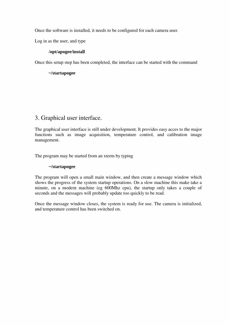
If a computer controlled telescope is being used, open the properties window("Options->Properties", or Alt-p), select the "Telescope" tab, and select the appropriatetelescope type from the pull down menu. (This facility is not yet completed, LX200support is expected for the next release of this package).
To configure a telescope operated remotely via a network, refer to the "Advanced Usage"chapter of this manual.
Select "File->Save" from the pull-down menu to save the changes to disk.
3.1.2 Normal usage
1. Select the image type (Object, Flat-field, Dark, etc)2. Adjust the exposure time as required3. Adjust the number of frames4. Optionally adjust the directory to be used to save images (defaults to the
startup directory)5. Adjust the image name. For sequences of images, the image number can be automatically inserted into the name at any position using a marker (%d). For example test_%d6. Click "Observe" (a sequence of frames may be terminated by clicking "Abort"
after the sequence has started).
The exposure(s) will now be taken and saved on disk in FITS format. If the "automaticdisplay" option is selected, then the image(s) will also be automatically be displayed inthe DS9 image viewer.
By default the raw image data is written to disk. The "auto-calibrate" option is used toselect automatic calibrations. When this option is enabled, the best (ie nearest temperature
match) calibration frames will automatically be loaded and applied. Please refer to the"Calibrations" chapter to learn how to create libraries of calibration data for this purpose.
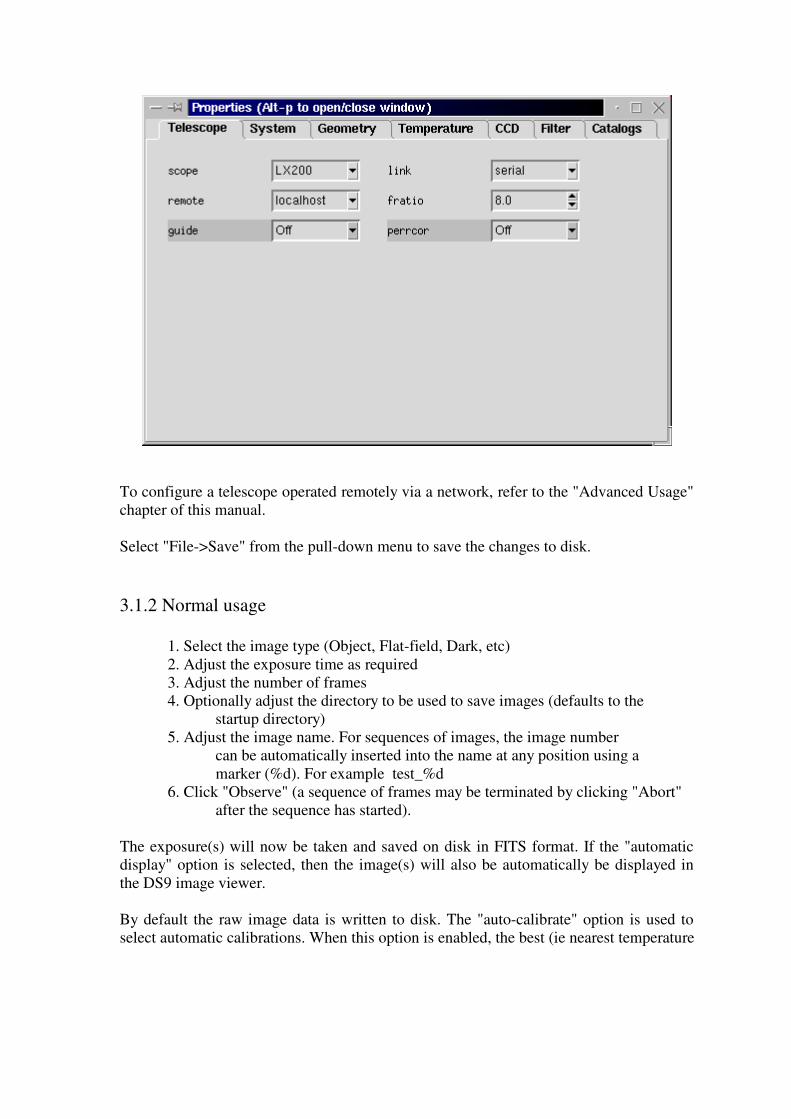
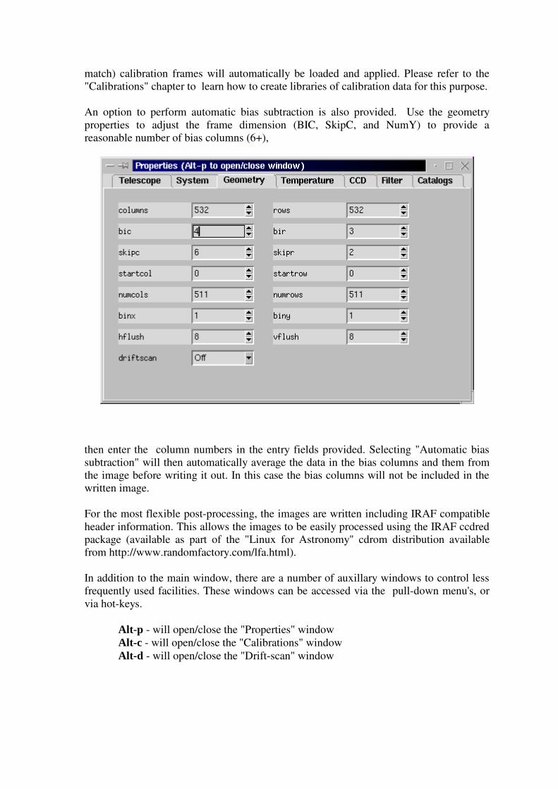
An option to perform automatic bias subtraction is also provided. Use the geometryproperties to adjust the frame dimension (BIC, SkipC, and NumY) to provide areasonable number of bias columns (6+),
then enter the column numbers in the entry fields provided. Selecting "Automatic biassubtraction" will then automatically average the data in the bias columns and them fromthe image before writing it out. In this case the bias columns will not be included in thewritten image.
For the most flexible post-processing, the images are written including IRAF compatibleheader information. This allows the images to be easily processed using the IRAF ccdredpackage (available as part of the "Linux for Astronomy" cdrom distribution availablefrom http://www.randomfactory.com/lfa.html).
In addition to the main window, there are a number of auxillary windows to control lessfrequently used facilities. These windows can be accessed via the pull-down menu's, orvia hot-keys.
Alt-p - will open/close the "Properties" windowAlt-c - will open/close the "Calibrations" windowAlt-d - will open/close the "Drift-scan" window

3.1.3 Region mode
To select a sub-region for readout
1. Ensure a full-frame image is displayed in DS92. Select "Observe->Region" from the pull-down menu3. Reply to the pop-up dialog (use current region or define a new one)4. For new regions, use the mouse to define the region in DS9 using a click-and-
drag motion5. Click the pop-up OK when ready6. Click "Observe"
Region mode may also be accessed via the "Observe->Continuous" pull-down menuentry. In this mode, the sub-region will be continuously exposed, readout, and displayed,until "Abort" is used to stop the sequence. This mode of operation should be useful formanual focusing. The subregions are not saved to disk when in continuous exposuremode.
3.1.4 Focus frame acquisition
Focus frames consist of multiple exposures, taken without reading out the image.Between each exposure, the image is shifted slightly on the detector (either by readingout a few lines, or by offsetting the telescope slightly), and the focus is also adjusted.
We use the detector shift method, as it also works on manual telescopes.
After each exposure, a pop-up dialog will appear. At this point, manually adjust the focusby a (hopefully) small known amount, then click OK. After all the exposures arecompleted, the frame is read out and written to disk. Special keywords are inserted intothe header to allow the IRAF imfocus task to automatically determine "best" focus (thisfeature is still under development).
Support for electronic focus position adjustment will be made available in future releasesof the package.
For systems where no electronic readback of focus position is available it can besimulated by attatching a calibrated disk to the focusser.

3.2 Properties window
The properties window can be accessed either by selecting "Options->Properties" fromthe pull-down menu, or by typing Alt-p whilst the pointer is in the main window. In eachcase repeating the operation will close the window again.
The window consists of a set of tabbed panels, click the tab name to view the panel.
Telescope panel
This panel is used to select the type of telescope in use. If your telescope is not yetsupported, or does not have computer control, then select "Manual". Enter the correctfocal ratio, remembering to take into account any focal reducers that are installed.
Use guide to select auto-guiding (NOT YET IMPLEMENTED)
Use perrcor to select automatic periodic-error-correction (NOT YET IMPLEMENTED)

System
This panel reports camera configuration parameters which will not normally need to bechanged, indeed many are readonly.
Geometry
This panel provides easy editing of all the relevant parameters to competely define thereadout region. Subregions can be defined by editing StartX, StartY, NumX and NumY.Binning can be set in each axis, and so on. Every change is immediately tested, and anyillegal combinations will cause the background color of the panel to change. It will not bepossible to obtain an image if an illegal combination is selected.
In general the only parameters which will be manually adjusted are the binning factors.Sub-region definition is more easily performed using the pull-down "Observe->Region"menu selection in the main window.
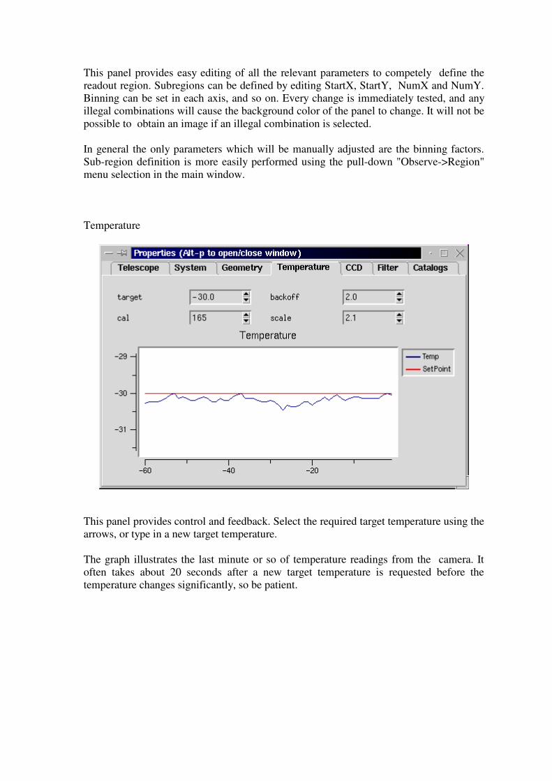
Temperature
This panel provides control and feedback. Select the required target temperature using thearrows, or type in a new target temperature.
The graph illustrates the last minute or so of temperature readings from the camera. Itoften takes about 20 seconds after a new target temperature is requested before thetemperature changes significantly, so be patient.
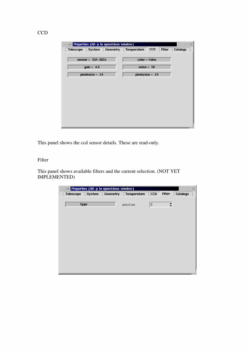
CCD
This panel shows the ccd sensor details. These are read-only.
Filter
This panel shows available filters and the current selection. (NOT YETIMPLEMENTED)
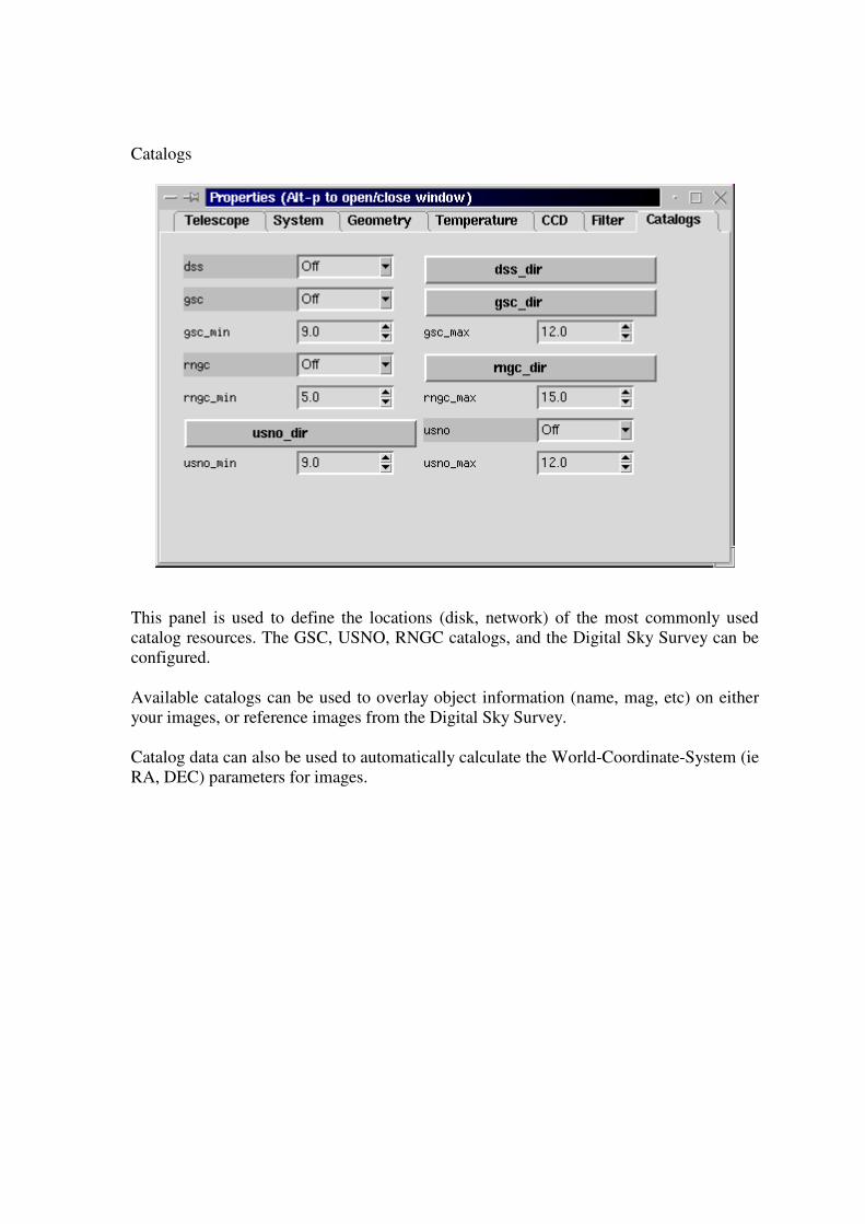
Catalogs
This panel is used to define the locations (disk, network) of the most commonly usedcatalog resources. The GSC, USNO, RNGC catalogs, and the Digital Sky Survey can beconfigured.
Available catalogs can be used to overlay object information (name, mag, etc) on eitheryour images, or reference images from the Digital Sky Survey.
Catalog data can also be used to automatically calculate the World-Coordinate-System (ieRA, DEC) parameters for images.

3.3 Calibrations
The calibrations window can be accessed either by selecting "Calibrations->[type]" fromthe pull-down menu, or by typing Alt-c whilst the pointer is in the main window. In eachcase repeating the operation will close the window again.
Obtaining the best performance from ccd cameras requires considerable calibration. Thiswindow provides a simple way to automate the collection of the most common types ofcalibration data.
A calibration run will often require careful preparation to ensure the best results.Each calibration run is specified using the following items
- location of directory used to store the data- number of frames to average to create each calibration frame- minimum temperature- maximum temperature- exposure duration
The directory to store calibration data may be independently specified for each categoryof calibration frame. Each category also has an associated "automatic" option, which,when selected will activate automatic calibration using that category (assuming that"automatic calibration" is enabled in the main GUI window.Clicking one of the "Start [type] calibration" buttons will pop-up a dialog which providesan estimate of the length of time required to run the full sequence (which can besubstantial).
The software steps through the range of temperatures selected (in 1 degree increments).At each temperature, a set of [n] frames is acquired. These frames are buffered inmemory. Once all [n] exposures have been acquired, the appropriate calculations aremade to generate the calibration frame, which is then written to disk.
Once a library of calibration frames has been obtained, they can automatically be appliedby selecting the "auto-calibrate" option in the main window.
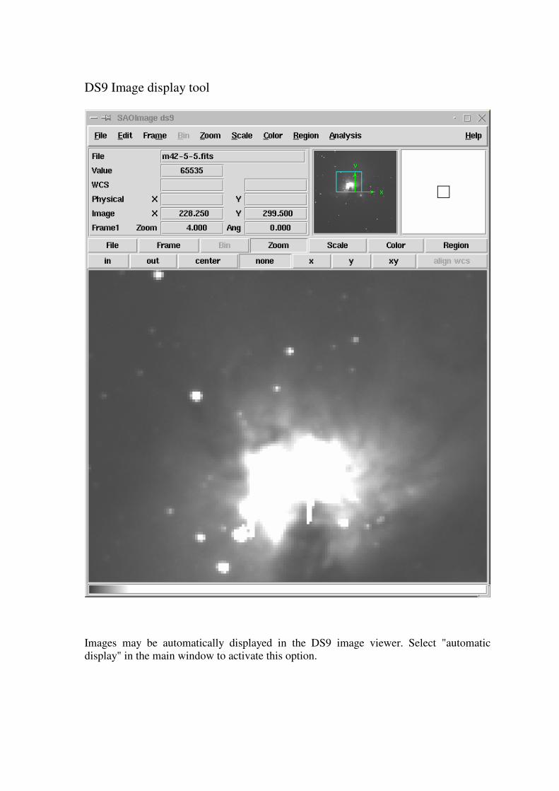
DS9 Image display tool
Images may be automatically displayed in the DS9 image viewer. Select "automaticdisplay" in the main window to activate this option.

The DS9 image viewer is a powerful tool. There is extensive online documentationavailable at
file:/opt/apogee/html/ds9/index.html
Most aspects are fairly intuitive, configuration is done using the pull-down menus;contrast/brightness is adjusted by holding down the left-mouse-button, and moving themouse around. The middle mouse button centers the image at the current location.
4.Advanced use.
4.1 Drift-scan operation
The driver is equipped with preliminary support for drift-scan operation. In this mode, thetelescope is set at a fixed position, and the sky allowed to drift through the field at thesidereal rate. The driver automatically reads out the ccd at the appropriate rate to correctfor the sidereal motion.
It is of course crucial that the rate be very accurately specified, and that the readoutsoftware does not get pre-empted by other processes in the system. It is recommendedthat during a drift-scan readout, no other major activity is taking place on the computer.
In drift-scan mode, the length of the exposure is limited only by available memory. Forexample if sufficient memory where available you could make a single drift-scan fromdusk until dawn. Of course, all the image data will be sitting in the memory of yourcomputer until the exposure completes, when the data is written to disk. Given thepossibility of a power failure or other computer problem, you should limit your drift-scanexposures to an hour or so, thus minimising data loss should the unthinkable occur.
Using drift-scan mode will require some setup effort on the part of the user.
Here is a checklist of steps we used to test this mode
1. Ensure that the telescope is VERY well polar aligned2. Switch off the telescope drive3. Point the telescope at the celestial equator (DEC=00:00:00)4. Use short normal mode exposures (~1 minute) to observe the direction of drift5. Align the ccd camera so that the stars drift down the ccd in perfect alignment with the ccd columns
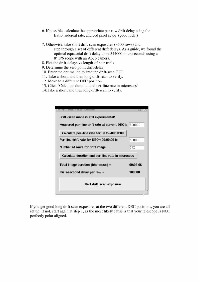
6. If possible, calculate the appropriate per-row drift delay using the fratio, sidereal rate, and ccd pixel scale (good luck!)
7. Otherwise, take short drift-scan exposures (~500 rows) and step through a set of different drift delays. As a guide, we found the optimal equatorial drift delay to be 344000 microseconds using a 8" F/6 scope with an Ap7p camera.8. Plot the drift-delays vs length-of-star-trails9. Determine the zero point drift-delay10. Enter the optimal delay into the drift-scan GUI.11. Take a short, and then long drift-scan to verify.12. Move to a different DEC position13. Click "Calculate duration and per-line rate in microsecs"14.Take a short, and then long drift-scan to verify.
If you get good long drift scan exposures at the two different DEC positions, you are allset up. If not, start again at step 1, as the most likely cause is that your telescope is NOTperfectly polar aligned.
4.2 Remote control
There are two methods for using the GUI via a remote computer.
1. Standard X-windows
Use the standard X-windows display redirection facility to point the display to another computer (named "other" for example).
eg. setenv DISPLAY other :0
The "xhost +ccd-name" command must also be issued on the "other" computer, to allow remote displays to take place (where ccd-name is the name of the camera control computer).
Finally , start the GUI as usual, the windows should appear on the "other" machine.
This method only works if both computer are running a *nix type operating system. X-windows is available for MS Windows, but it is usually expensive.
2. VNC
Use the VNC (Virtual network computing) software (which is free, and open-source).This package supports the remote viewing on the ccd GUI desktop on *nix, windows,and Mac platforms. Even better, multiple remote users can simultaneously view the samedekstop, and even share interaction rights with the applications. Given fast networkconnections (fast ethernet) this is a near optimal solution. The VNC package is just one ofthe items in the bundle of extras included in the cdrom version of the Linux ApogeeDrivers cd, available from The Random Factory.
Future releases of the driver will also include support for true client/server use ofcameras. In this situation, the GUI will actually run on the remote machine, and only thelow level camera access code will run on the camera controller computer.
5. External packages
The Linux Apogee camera driver is free, open source software. However, we do offer anenhanced distribution on cdrom, which adds a wealth of extra tools for both user anddeveloper.

The following list describes the current contents of the cd distribution
SWIGManual.pdf - User manual for the Simple Wrapper and Interface Generator packageapogee_devel.tar.gz - Developers version of the driversapogee_runtime.tar.gz - Standard runtime, user distributionastrotcl-1.4.4.src.tar.gz - A set of astronomical tools for tclccdlinux-modaudine.tar.gz - The drivers for for the Audine/Gemini open-hardware camerascfitsio-2.0.3-4.i386.rpm - C language FITS utilitiesds9.2.0.tar.gz - The DS9 sourcesds9.linux.2.0.tar.gz - DS9 for Linux fiasco-1.0.tar.gz - Image compression packagefitsTcl-2-0.i386.rpm - FITS tools for tclftools-2-4.i386.rpm - Massive astronomical data reduction suite in C/tclgimp-1.2.0.tar.gz - Image manipulation package with extensive capabilitiesgimp-data-extras-1.2.0.tar.gz - Add-ons for GIMPgsl-0.4-1.i386.rpm - GNU scientific subroutinesimlib-1.9.7-3.i386.rpm - Image management/conversion libraryimlib-cfgeditor-1.9.7-3.i386.rpm - extras for imlibimlib-devel-1.9.7-3.i386.rpm - devlopers version of imliblibjpeg-6b-10.i386.rpm - jpeg librarylibjpeg-devel-6b-10.i386.rpm - developers version of jpeg librarylibpng-1.0.5-3.i386.rpm - PNG librarylibpng-devel-1.0.5-3.i386.rpm - developers version of PNG librarylibtiff-3.5.4-5.i386.rpm - TIFF librarylibtiff-devel-3.5.4-5.i386.rpm - developers version of TIFF librarynetpbm.tar.gz - large set of image conversion utilitiesnovas-c-2-0.i386.rpm - Astrometry routines from the US Naval Observatoryopt - Full unpacked developers version of drivers for easy browsingpython-1.5.2-13.i386.rpm - The python scripting languagepython-devel-1.5.2-13.i386.rpm - developers version of pythonpython-docs-1.5.2-13.i386.rpm - extensive documentation for pythonpython-tools-1.5.2-13.i386.rpm - extra tools for pythonpythonlib-1.23-1.noarch.rpm - python librariessexarticle.ps.gz - description of sextractorsextractor-2.1-0.i386.rpm - automatic star/galaxy location skycat-2.5-3.i386.rpm - feature rich image viewer/catalog accessswig1.3a5.tar.gz - Simple wrapper and interface generator vnc-3.3.2r3_unixsrc.tgz - virtual network computing unix sourcevnc-3.3.3beta2_ppc_mac.sit - virtual network computing for macvnc-3.3.3r2_x86_linux_2.0.tgz - virtual network computing for linuxvnc-3.3.3r7_x86_win32.zip - virtual network computing for windowsxite-3-4.i386.rpm - Image processing tools
The Random Factory also produces a very extensive collection of Astronomical softwareall pre-compiled for Linux. The current release (Volumes 5 & 6) includes over 2GB ofsoftware on a 2-cdrom set.

Appendix 1 - Processing CCD images
This advice is paraphrased from the advice provided to professional Astronomersobserving at the US National Observatory. It is based on a document included with theIRAF system, and was written by Dr. Phil Massey (currently at Lowell Observatory).
What Calibration Frames Do You Need?
The answer to this depends to some extent on what it is that you are doing. The goal is tonot let the quality of the calibration data degrade your signal-to-noise in any way. If youare in the regime where the read-noise of the chip is the dominant source of noise on yourprogram objects, then subtracting a single "bias frame" from your data would increasethe noise prohibitively.
However, if you instead use the average of 25 bias frames, the noise will be increased by only 10%. Of course, if you are into high signal-to-noise spectroscopy, so you have lotsand lots of signal compared to read-noise, or if you have high sky background on directimages, so that read-noise is again immaterial, then the signal-to-noise will be littleaffected by whether you have only a few bias frames. However, in this regime the qualityof your flat fielding is all important if you want to get the most out of your data. The following list contains the type of calibration images you may need, and providessome guide to the consideration of how many you may want to have. bias frames.
These are zero second integration exposures obtained with the same pre-flash (if any) youare using on your objects. If read-noise will sometimes dominate your source of error onthe objects, take 25 bias frames per night. Take them over dinner and you'll never noticeit. You will want to have a new sequence of these each day. dark frames.
These are long exposures taken with the shutter closed. If your longest exposure time isover 15 minutes you may want to take an equal length dark frame, subtract a bias framefrom it, and decide if you are worried about how much dark current is left. Applicationswhere dark current will matter are long-slit spectroscopy and surface brightness studies --cases where the background is not removed locally. If you do find that you need to takecare of dark current, then you should take at least 3 and preferably 5 to 10 dark framesduring your run, each with an integration time equal to your longest exposure. Youshould ensure that your system is sufficiently light-tight to permit these to be done duringthe day.
flat field exposures.
At a minimum, flat field exposures are used to remove pixel-to-pixel variations acrossthe chip. Usually dome flats (exposures of an illuminated white board) will suffice toremove the pixel-to-pixel stuff. You will want to expose the dome or projector flats sothat you get sufficient counts to not degrade the signal-to-noise of the final images. If youare after 1% photometry per pixel then you will need to have several times more than10,000 electrons accumulated in your flats, but you need to be careful not to exceed thegood linearity limit in any single flat exposure. Generally if you have 5 or more flats eachwith 10,000 electrons per pixel you are probably fine. You will need a set like this forevery filter, and you probably will want to do a new sequence every day. twilight flats.
If you are interested in good photometry of objects across your field, you need to know ifthe sky looks different to your CCD than the dome flat. It is not unusual to find 5-10% gradients in the illumination response between a flat and a sky exposure, and thisdifference will translate directly into a 5-10% error in your photometry. For mostapplications, exposures of bright twilight sky (either for direct imaging or spectroscopy)will cure this problem. With direct imaging this requires you to be very quick on your feetto obtain a good level of sky exposure in each of your filters while the sky is gettingdarker and darker. (Only the truly desperate would take twilight flats in the morning!)For direct imaging I would recommend 3 to 5 exposures in each filter, stepping thetelescope slightly in between the exposures so that any faint stars can be effectivelycleaned out. You will find that you need to keep increasing the exposure time to maintainan illumination level of 10,000 electrons. blank dark sky exposures.
Some observers doing sky-limited direct imaging may wish to tryexposures of blank sky fields rather than twilight sky, as the color of twilight and thecolor the dark sky do differ considerably. Obtain at least three, and preferably four, longexposures through each filter of some region relatively free from stars , stepping thetelescope 10-15 arcseconds between each exposure. The trick here, of course, is to getenough counts in the sky exposures to make this worth your while. Unless you are willingto devote a great deal of telescope time to this, you will have to smooth these blank darksky exposures to reduce noise, but the assumption in such a smoothing process is that thecolor response of the chip does not vary over the area you are smoothing. You might trydividing a U dome flat by a V dome flat and seeing how reasonable an assumption thismight be. Also, if the cosmetics are very bad the smoothing process will wreak havocwith your data if you are not successful in cleaning out bad columns and pixels.

This section will br iefly outline what we will do with the calibration images. Most of the calibration data is intended to remove "additive" effects: the electronicpedestal level (measured from the overscan region on each of your frames), the pre-flashlevel (measured from your bias frames), and, if necessary, the dark current. The flat field data (dome and twilight sky exposures) will remove the multiplicative gain andillumination variations across the chip. When you obtained your frames at the telescope, the output signal was "biased" byadding a pedestal level of several hundred ADU's. We need to determine this bias levelfor each frame individually, as it is not stabilized, and will vary slightly (ss 5-30 ADU's)with telescope position, temperature, and who knows what else. Furthermore, the biaslevel is usually a slight function of position on the chip, varying primarily alongcolumns. We can remove this bias level to first-order by using the data in the overscanregion, the (typically) 32 columns at the right edge of your frames.
data
We will average the data over all the columns in the overscan region, and fit these valuesas a function of line-number (i.e., average in the "x" direction within the overscan region,and fit these as a function of "y"). This fit will be subtracted from each column in yourframe; this "fit" may be a simple constant. At this point we will chop off the overscanregion, and keep only the part of the image containing useful data. This latter step usuallytrims off not only the overscan region but the first and last few rows and columns of yourdata. If you pre-flashed the chip with light before each exposure, there will still be a non-zeroamount of counts that have been superimposed on each image. This extra signal is alsoan additive amount, and needs to be subtracted from your data. In addition, there may becolumn-to-column variation in the structure of the bias level, and this would not havebeen removed by the above procedure. To remove both the pre-flash (if any) and theresidual variation in the bias level (if any) we will make use of frames that you haveobtained with a zero integration time. These are referred to in IRAF as "zero frames"may also be called "bias frames". We need to average many of these (taken with pre-flashif you were using pre-flash on your object frames), process the average as describedabove, and subtract this frame from all the other frames.
"Dark current" is also additive. On some CCD's there is a non-negligible amount ofbackground added during long exposures. If necessary, you can remove the dark currentto first-order by taking " dark" exposures (long integrations with the shutter closed),process- ing these frames as above, and then scaling to the exposure time of yourprogram frames. However, it's been my experience that the dark current seldom scaleslinearly, so you need to be careful. Furthermore, you will need at least 3 dark frames inorder to remove radiation events ("cosmic rays"), and unless you have a vast number ofdark exposures to average you may decrease your signal-to-noise;The bottom line of all this is that unless you really need to remove the dark current, don'tbother. The next step in removing the instrumental signature is to flat-field your data. This willremove the pixel-to-pixel gain variations, and (in the case direct imaging) the larger-scale spatial variations. If you are doing direct imaging, then you are probably happy bynormalizing the flat-field exposures to some average value.
The final step in the flat-fielding process is to see if your twilight sky exposures havebeen well flattened by this procedure--if not, we may have to correct for this.
Apogee camera driver - Programmers Guide V0.5
Dave Mills([email protected]) - December 2001
Contents
1.CameraIO object2.Scripting interfaceTcl3.Code generation4.Tcl/Tk and loadable libraries5.Ccd library6.LX library7. Remote control
1. CameraIO object
In the unlikely event that you should find it necessary to use the C++ interface directly,there is a small sample of code in the file
/opt/apogee/src/apogee/CCameraIO_example.cpp.
This code should be easily comprehensible to anyone familiar with C++. For example tocreate a new camera object
cam = new CCameraIO;
To call a method, for example InitDriver
result = cam->InitDr iver(cameraNumber);
To set the value of an instance variable
cam->BaseAddress = 0x378;
2. Scripting interface
The simplest way to program using the driver is via the provided scripting interfacelibraries. An interface is provided for the Tcl/Tk language. This language is easy to learndue to its interpretive nature. That is, you type commands directly to a command line, andthey are executed immediately.
Interfaces to other languages (python, perl, and more) can also be automatically generatedusing the SWIG package (included in the "devel" release of the package).

2.1 Tcl
To begin a Tcl/Tk session, open an X-terminal, start a csh shell and prepare theenvironment by typing
source /opt/apogee/scr ipts/setup.env (prepares the environment)
This will initalize your shell to use the included version of "wish" , the Tcl/Tk windowingshell. Another version of "wish" may already be installed on the system, but it isrecommended that the included version be used to avoid and potential library versionconflicts.
/opt/apogee/bin/wish8.3 (starts the tcl/tk shell)
A small gray window will open. Re-select your xterm window and type
source /opt/apogee/scr ipts/camera_init.tcl (command line only)
or
source /opt/apogee/scr ipts/gui.tcl (gui interface plus command line)
The appropriate driver library will be dynamically loaded, and new commands will beadded to the Tcl shell. Type a "?" at the prompt to get a list of all the commands Tcl iscurrently aware of.
The camera_init script also creates a CAMERA variable which acts as a software pointerto the C++ structure used to control the camera.
Tcl commands typically protect the user against incorrect usage. For example theCAMERA object may be commanded using the syntax
$CAMERA command [arg1] [arg2] ...
Typing
$CAMERA xyzzy
will result in an error report (because "xyzzy" is not a valid camera command!). Thiserror report helpfully includes a list of all the commands that the $CAMERA referencedobject does understand.

The most useful commands are listed below.
$CAMERA InitDr iver cameraNumber
This command needs no additional arguments, it performs camera initialization. It willnot normally be necessary to use this call, as it will have been done as part of thecamera_init.tcl script.
$CAMERA read_Status
This command returns an integer representing the readout status of the camera. Typicallythis will be stored in a tcl variable, and then printed out in user friendly format. E.g.
set s [$CAMERA read_Status] switch $s { 0 {set t " Idle" } 1 {set t " waiting for tr igger" } 2 {set t " exposing" } 3 {set t " downloading" } 4 {set t " line ready" } 5 {set t " image ready" } 6 {set t " flushing BIR" } default {set t " ERROR code $s" } } puts stdout " Camera status is $s"
$CAMERA Expose duration shutter
Take an exposure of the requested duration (expressed in seconds). The value of theshutter argument is either 0 - leave shutter closed, or 1 - open shutter during exposure.
$CAMERA GetImage
This command reads out the entire frame and saves it in memory.
$CAMERA Buffer Image testname
This command retrieves the image from the camera, and saves it in the PC'smemory/swap-space. Any number of images can be buffered in this way, subject toavailable memory.
Once the image is in memory it can be manipulated using the commands from the Ccdlibrary. For example
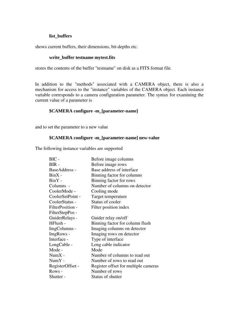
list_buffers
shows current buffers, their dimensions, bit-depths etc.
write_buffer testname mytest.fits
stores the contents of the buffer "testname" on disk as a FITS format file.
In addition to the "methods" associated with a CAMERA object, there is also amechanism for access to the "instance" variables of the CAMERA object. Each instancevariable corresponds to a camera configuration parameter. The syntax for examining thecurrent value of a parameter is
$CAMERA configure -m_[parameter-name]
and to set the parameter to a new value
$CAMERA configure -m_[parameter-name] new-value
The following instance variables are supported
BIC - Before image columnsBIR - Before image rowsBaseAddress - Base address of interfaceBinX - Binning factor for columnsBinY - Binning factor for rowsColumns - Number of columns on detectorCoolerMode - Cooling modeCoolerSetPoint - Target temperatureCoolerStatus - Status of cooler FilterPosition - Filter position indexFilterStepPos - GuiderRelays - Guider relay on/offHFlush - Binning factor for column flushImgColumns - Imaging columns on detectorImgRows - Imaging rows on detectorInterface - Type of interfaceLongCable - Long cable indicatorMode - Mode NumX - Number of columns to read outNumY - Number of rows to read outRegisterOffset - Register offset for multiple cameras Rows - Number of rowsShutter - Status of shutter

SkipC - Number of skip columnsSkipR - Number of skip rowsStartX - First column to read outStartY - First row to read outStatus - Camera readout statusTDI - Drift mode TempScale - Scale multiplier for raw temperature Temperature - Current ccd temperatureTest2Bits - Second set of test bitsTestBits - Primary set of test bitsTimeout - Image readout timeoutUseTrigger - Trigger statusVFlush - Binning factor for vertical flush
For example, the following commands would prepare the readout region
$CAMERA configure -m_Star tX 100$CAMERA configure -m_Star tY 100$CAMERA configure -m_NumX 64$CAMERA configure -m_NumY 64
would specify a 64x64 pixel region starting at column 100, and row 100.
The camera_init.tcl script includes code to interrogate the C++ level API and construct ageneric interface to all the available methods and instance variables which can read/writecamera parameters. The names of parameters which may be read can be found asmembers of the global array CCAPIR, and those which can be written can be found asmembers of the global array CCAPIW.
The element of arrays can be examined using the syntax, e.g. for CCAPIW
array names CCAPIW
3. Code generation
The scripting interfaces are created using a mixture of custom code (the Ccd library), andan automatically generated interface. The automatically generated portion is created usingSWIG (Simple Wrapper and Interface Generator).
Note that older versions of SWIG may not be capable of generating functioning wrappercode for C++/Tcl. Please use the included version (1.3a5 or later).
SWIG is very easy to use. All that is required is a .i file which defines the methods andinstance variables for the object. In many cases this file can be copied directly from the .hheader file for the object.
Once the .i file has been prepared, the wrapper code can be generated using a commandsuch as
/usr /local/bin/swig -tcl8 -c++ apogeePPI .i
Note that there is a slightly different file for each interface type. This allows us togenerate shared libraries which are named according to the interface type.
To add a new method to the CCameraIO object, the following steps are required
- add C++ code for the method to CameraIO_Linux[interface].cpp- add definitions to CameraIO_Linux.h- add the same definitions to apogee[interface].i
Once the revised CameraIO_Linux[ interface] .cpp and apogee[ interface] .i code has beensucessfully compiled, e.g. for an ISA interface
g++ -O2 -g -fpic -c CameraIO_LinuxISA.cpp -DLINUX -I ../../include/usr /local/bin/swig -tcl8 -c++ apogeeISA.i
then you are ready to build the shared library using a command such as
g++ -shared -O2 -g apogeeISA_wrap.c CameraIO_LinuxISA.o \ -o apogee_ISA.so -I .
The Camera interface is now ready to load into a wish shell using
load ./apogee_ISA.so (invoked from a tcl/wish shell)
SWIG is also capable of generating code for other scripting languages (for examplepython). Refer to the SWIG manual for details.
4. Tcl/tk and dynamic libraries
The most recent versions of Tcl/Tk have extensive support for dynamically loadinglibraries of code. The Apogee Linux GUI makes extensive use of this capability to tunethe behaviour of the interface depending upon the facilities available.
Dynamically loadable libraries are provided for the following
- Apogee parallel port interface cameras- Apogee ISA interface cameras- Ccd frame in-memory buffering/processing- FitsTCL FITS file access- LX200 serial interface- Compressed GSC catalog access- Digital sky survey access- Astrometry library (NOT YET IMPLEMENTED)- BLT graphics library
In all cases libraries are loaded into a running wish by typing a command(or including the command in a source'd script) such as
load [path-to-library]lib[name].so
To create a new loadable library, the following files will normally be required (assuminga package name of "newpack")
newpackPackage.c - stub code to define the namespace, test, and call initialization code
newpackVersion.c - stub code to specify version infonewpack.c - the implementation
The implementation will typically consist of a routine named "newpackAppInit" whichdefines the available commands, plus code for the commands themselves.
The interface from Tcl to C is easy to use. The code in /opt/apogee/src/ccd can serve as atemplate for the most common functionality.

5. CCD library
The Ccd library can be interactively loaded into a wish shell using the command
load /opt/apogee/lib/libccd.so
The Ccd loadable library is a Tcl extension which provides simple commands formanipulating the raw data generated by the readout of a CCD camera.
The following commands are available
read_image - load a FITS file into an in-memory bufferwrite_image - write raw image data to a FITS filewrite_cimage - write bias subtracted image data to a FITS filewrite_dimage - calculate "dark" frame and write to FITS filewrite_zimage - calculate "zero" frame and write to FITS filewrite_fimage - calculate "flat" image and write to FITS filewrite_simage - calculate "sky-flat" image and write to FITS fileshmem_image - copy image data to a shared memory segmentshow_image - transfer image data to DS9 via shared memorystore_calib - calibrate the current in-memory framewrite_calibrated - calibrate and save to disklist_buffers - print a list of in-memory buffered imagesset_biascols - specify the bias columnsset_biasrows - specify the bias rows
The Ccd library commands interact swith Apogee drivers in the following manner
- a driver library "BufferImage" call will store an imaqe in a named memory buffer- Ccd library calls then reference the image by that name
For example
$CAMERA Expose 10 1$CAMERA Buffer Image testimagewr ite_image testimage myfile.fits
would take a 10 second exposure (with the shutter open), read-out the image, and store itin a buffer named "testimage", and finally write the raw image data to a disk FITS filenamed "myfile.fits" The syntax required for each call can be determined interactively bysimply calling the function without any arguments. The required syntax will then beprinted out.
Future versions of this library will include image arithmetic and conversion functions.

6. LX library
The LX library can be interactively loaded into a wish shell using the command
load /opt/apogee/lib/liblx200.so
The LX200 loadable library is a Tcl extension which provides simple commands forinteracting with a telescope which support the protocol used by LX200 series telescopes.
The following commands are available
open_scope - open a link (serial) to the telescopeclose_scope - close the link to the telescopelx200_mode - query the telescope modelx200_clockfmt - query the clock format in effectlx200_goto - slew to targetlx200_object - define target from cataloglx200_ext - define target from extended catalogwrite_scope - send low level command to scopelx200_set_date - set the datelx200_set_filter - set filterlx200_set_site - set site detailslx200_set - generic parameter setlx200_pos - set position (ra,dec)read_scope - low level read from scopelx200_obj_sync - sync on current position
The syntax required for each call can be determined interactively by simply calling thefunction without any arguments. The required syntax will then be printed out.
Future versions of this library will include support for automated observation scriptingwith multiple objects, filters, etc.
7. Remote use (Not Yet Implemented) The software bundle includes a comprehensive solution for remote control of camera andtelescope functions. Every function in each loadable libary can also be enabled forremote access by appending the "-server [portnum]" specifier to the GUI startupcommand.
In this case the local interface will not display any of the elements of the graphicalinterface, but will open a socket and accept future commands via that channel.
The remote machine should then start a copy of the GUI using the syntax
/opt/apogee/bin/apogeegui -remote [server ]:[por tnum]