apolloapollo dlg dlg dlg - hobbyking · discus launch gdiscus launch gliderliderlider...
TRANSCRIPT

ApolloApolloApolloApollo DLG DLG DLG DLG Discus Launch GDiscus Launch GDiscus Launch GDiscus Launch Gliderliderliderlider
Almost-Ready-to-Fly
Instruction Manual
Specifications
Wing Span: 1550mm (61in)
Length: 1050mm (41in)
Wing area: 24.5sq dm (358sq in)
Weight (kit): 350g (12.35oz)
Airfoil: MH32

www.valuehobby.com/apollo-dlg.html
2
Dear Customer,
Congratulations on your purchase of Apollo DLG from Value Hobby. We thank you for your generous support,
and hope you enjoy your new airplane.
At Value Hobby, we hope to offer competitive prices, good performance, and products that you can setup and
use with ease. That’s why we extensively researched and tested this airplane, and suggested all the products
necessary for you to setup properly. We understand that you have many choices when purchasing, and we are
grateful you choose to buy from us.
As vendors, one of the most gratifying things for us is to hear from our customers. We would welcome any
suggestion to help us improve. Please make us aware of any errors and imperfections in the airplane or the
instructions, or about the setup that we suggested. We hope you’ll find our setup suggestions to be helpful, and
enjoy flying your new airplane. Please feel free to contact us at (630) 948-0947 or email us at
Disclaimer
By purchasing and/or building this model, user assumes ALL liability and risk involved with this product. This
model should be built and flown by an experienced pilot and only flown at AMA sanctioned sites.
Value Hobby guarantees this model to be free of defects in materials and workmanship at the date of purchase.
This warranty does not cover any parts damaged by use or modifications. In no way shall Value Hobby’s liability
exceed the original cost of the purchased model. Further, Value Hobby reserves the right to modify this warranty
without notice. Value Hobby has no control over the final stages of assembly or the material used for the final
assembly. No liability shall be assumed nor materials used for the final user-assembled product. By the act of
using the final product the user accepts all resulting liability. Value Hobby, as a R/C product vendor, provides a
top quality airplane and instructions to complete the model. The quality and flight characteristics of the finished
model depend greatly on how it is built; we cannot guarantee the performance for the completed model and
representations are expressed or implied as to the performance of the completed model. If the buyer is not
prepared to accept the liability associated with the use of this product, the buyer is advised to return this kit
immediately, in new and unused condition.
Safety in Assembly
During assembly of this aircraft, you will be asked to use sharp knives and hobby adhesives. Please follow all
safety procedures recommended by the manufacturers of the products you use, and always follow these
important guidelines:
ALWAYS protect your eyes when working with adhesives, knives, or tools, especially power tools. Safety glasses
are the best way to protect your eyes.
ALWAYS protect your body, especially your hands and fingers when using adhesives, knives, or tools, especially
power tools. Do not cut toward exposed skin with hobby knives. Do not place hobby knives on tables or benches
where they can roll off or be knocked off.
ALWAYS have a first-aid kit handy when working with adhesives, knives, or tools, especially power tools.
ALWAYS keep hobby equipment and supplies out of the reach of children.

www.valuehobby.com/apollo-dlg.html
3
Safety in Flying
This is NOT a toy! It is a very high-performance RC airplane capable of high speeds and extreme maneuvers. It
should only be operated by a competent pilot in a safe area with proper supervision.
ONLY fly your aircraft in a safe, open area, away from spectators and vehicles–and where it is legal to fly.
NEVER fly over an unsafe area, such as a road or street.
Never fly too close to yourself or spectators.
Never run your motor inside a house or building with the propeller attached – Remove the prop for safety.
Required Items
CA Glue – Thin and Thick
Epoxy glue
Hobby Knife
Small Phillips Screwdriver
Set Metric Allen Wrenches
Scissors
Small Pliers
Wire Cutters
Masking tape
Optional – Heat gun
Before Starting Assembly
Examination
Unpack your airplane and examine the components. Check for damage of any kind. If you see any damage,
please contact Value Hobby immediately.
Covering
Your airplane was packed in plastic at the factory without any wrinkles in the covering. You may notice some
wrinkles now; more likely, you will notice a few in a day or two or the first time you take the plane out to the
flying field. These wrinkles are the result of wood shrinkage and/or expansion. Balsa wood changes size and
shape slightly as it is exposed to varying humidity in the air. This is a natural property of balsa wood. As your
airplane adjusts to the weather in your part of the world, wrinkles may appear and disappear. Wrinkles may be
removed with the gentle application of heat to the covering material on your airplane. The best tool to use is a
hobby heat gun. Apply the heat gently: the covering material will shrink as you apply the heat, and this will
remove the wrinkles. BE CAREFUL! Too much heat applied too quickly can damage the covering, either by
causing it to pull away from the wood at seams and corners or even by melting it. The covering will shrink at low
temperature with patient application of heat.
Wrinkles in the covering DO NOT affect flight performance.
Remove the canopy before attempting to use heat on your covering! The canopy is made of thermo-activated
plastic and WILL deform with the application of heat. Do not apply heat to the canopy.
If you need to clean your airplane, we recommend using a damp towel. The paint used on the canopy and cowl is
not safe for all cleaners. In particular, DO NOT use alcohol on these parts, it will remove the paint

www.valuehobby.com/apollo-dlg.html
4
Recommended Setup
Main Parts of the Airplane
Accessories and small parts not pictured
Configuration Model Qty
Radio 4 channel 1
Speed Control 3A Brushless ESC 1
Recommended
Battery′LiPO″ GForce 20C 240mAh 2S 7.4V LiPO 1
Servos 9g servos 4
Y-Harness Universal Servo Y-Harness ′300mm″11.8-Inch (Futaba "J" and
JR Compatible) 1
Extension Universal Servo Extension ′600mm″23.6-Inch (Futaba "J" and
JR Compatible) 2
Charger GT POWER X-CHARGER C6 6S LiPO Charger 1

www.valuehobby.com/apollo-dlg.html
5
Section 1: Horizontal Tail Installation
Step1. Locate the horizontal tail wing.(The
measurement shows the location of the mounting
block).
Step2. Remove the covering for the tail boom
mounting block on the horizontal stabilizer.
Step3. Mix some epoxy, and glue the mounting block
onto the stabilizer.
Step4. Place the tail boom on the horizontal tail and
adjust tail boom to make the distance of AB is 400mm
(15.7in).
Step5. Apply some epoxy to glue the tail boom to the
mounting block. (Adjust the horizontal tail to make it
parallel to the wing).
Step6. Use a clamp to hold the tail boom and block
until the epoxy cures. (Clamp sold separately.)

www.valuehobby.com/apollo-dlg.html
6
Section 2: Vertical Tail Installation
Step1. Mark on the vertical fin where 70mm (2.8in)
from the left edge of the vertical tail is.
Step2. Insert the vertical tail into the tail boom and
adjust the vertical tail to make the left edge of tail
boom is aligned with the marked line.
Use a felt-tipped pen to trace the outline of the tail
boom onto the vertical stabilizer.
Step3. Cut and trim the coverings inside the lines
drawn in the pervious step, and remove it.
Step4. Use the CA to glue the vertical tail to the tail
boom. (Adjust to make the vertical tail perpendicular
to the wing).
Note: As shown, when finishing the installation. A=A1,
B=B1, C=C1

www.valuehobby.com/apollo-dlg.html
7
Section 3: Elevator and Rudder Servo
and Linkage Installation
Step1. Install two servos on the servo mounts.
Step2. Thread the 790mm (31.1in) pushrod wire into
the tail boom. The z-bend will be towards the tail.
Step3. Install the servo arm with pushrod connector
in the servo. Center the servo arm electronically and
slide the pushrod wire into the connector.
Step4. Thread the pushrod wire into the clevis and
tighten the bolt.
Connect the clevis to the control horn.
Position the control horn on the rudder, the pushrod
wire will be aligned with the tail boom, and drill the
mounting holes for the bolts.
Step5. Use three M2*10mm (.4in) bolts to secure the
control horn to the rudder.
Step6. Center the control surface and tighten the
screw on the pushrod connector.

www.valuehobby.com/apollo-dlg.html
8
Step7. Finish the elevator servo and linkage
installation in the same way.
Section 4: Aileron Servo and Linkage
Installation.
Step1. Locate the items shown in the picture.
Step2. Glue two servo mounting blocks to the hatch
inside the markings.
Step3. Use two M2*8mm (.3in) self-tapping screws to
secure the two blocks wont loose. (Center the servo
arm before mounting.)
Step4. Use two M2*8mm (.3in)self-tapping screws to
mount the servo to the blocks.
Step5. Remove the coverings on the wing for the
servo wires as shown.
Step6. Thread the servo wire through the wing.

www.valuehobby.com/apollo-dlg.html
9
Step7. Thread the clevis onto the aileron pushrod and
connect the clevis to the servo arm.
Mount the servo hatch to the wing using four
M2*8mm (.3in) self-tapping screws.
Step8. Use glue and two hinges to attach the aileron
to the wing.
Step9. With the pushrod wire 90-degrees to the hinge
line, connect the pushrod wire to the servo control
horn using a pushrod connector.
Step10. Repeat the pervious steps to finish the other
aileron servo installation.
Section 5: Wing Installation
Step1. Locate the items shown in the picture.
Step2. Insert the two wing tubes
{10mm(.4in)*128mm(5.0in) and Ф80mm(3.1in)}into
the wing panel, and slide the other panel onto wing
tube.
Step3. Attach the wing onto the fuselage using two
bolts plate and four M3 Allen bolts. Tighten the bolts
using a screwdriver. {Two M3*30mm (1.2in) bolts are
for the front plate, and two M3*25mm (1.0in) bolts
for the other one}.
www.valuehobby.com/apollo-dlg.html
10
Section 6: Battery Installation
Install the battery into the fuselage as shown. Sponge
can be used to prevent the battery from moving.
Section 7: Canopy Installation
Use a M2*8mm (.3in) self-tapping screw to secure
the canopy onto the fuselage.
Section 8: Throwing Peg Installation
If you are right handed, remove the covering from the
hole in the left wing tip. If you are left handed,
remove the covering from the hole in the right wing
tip.
Push the carbon throwing peg into the hole in the
wing tip. Apply a small amount of epoxy to the peg
and twist the peg so that the epoxy goes into the
wing and the peg is centered vertically in the wing.
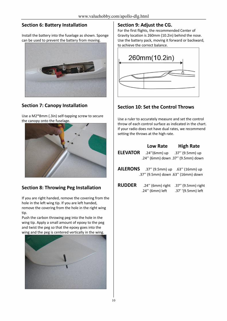
Section 9: Adjust the CG. For the first flights, the recommended Center of
Gravity location is 260mm (10.2in) behind the nose.
Use the battery pack, moving it forward or backward,
to achieve the correct balance.
Section 10: Set the Control Throws
Use a ruler to accurately measure and set the control
throw of each control surface as indicated in the chart.
If your radio does not have dual rates, we recommend
setting the throws at the high rate.
Low Rate High Rate
ELEVATOR .24’’(6mm) up .37’’ (9.5mm) up
.24’’ (6mm) down .37’’ (9.5mm) down
AILERONS .37’’ (9.5mm) up .63’’ (16mm) up
.37’’ (9.5mm) down .63’’ (16mm) down
RUDDER .24’’ (6mm) right .37’’ (9.5mm) right
.24’’ (6mm) left .37’ ’(9.5mm) left
www.valuehobby.com/apollo-dlg.html
11
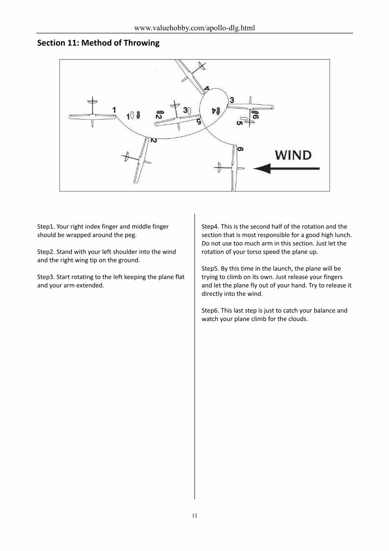
Section 11: Method of Throwing
Step1. Your right index finger and middle finger
should be wrapped around the peg.
Step2. Stand with your left shoulder into the wind
and the right wing tip on the ground.
Step3. Start rotating to the left keeping the plane flat
and your arm extended.
Step4. This is the second half of the rotation and the
section that is most responsible for a good high lunch.
Do not use too much arm in this section. Just let the
rotation of your torso speed the plane up.
Step5. By this time in the launch, the plane will be
trying to climb on its own. Just release your fingers
and let the plane fly out of your hand. Try to release it
directly into the wind.
Step6. This last step is just to catch your balance and
watch your plane climb for the clouds.

www.valuehobby.com/apollo-dlg.html
12
www.valuehobby.com
2012-10-29