appe·nd i·ces. - parliament of victoria€¦ · 0 764 2. 1'he a.c. high voltage system. the...
TRANSCRIPT

1103
APPE·ND I·CES.
16998.
INDEX TO APPEND ICES.
RAILWAYS ELECTRIFICATlON
Various systems explained and illustrated by :M:r. W. Karplus, Chief Engineer of Messrs. Siemens Bros'. Dynamo Works, London . . . . . . . . . . • • •• . •
Economic features of continuous current system best adapted for the suburban lines at Melbourne, submitted by the General Electric Company, Schenectady, N.Y., U.S.A.
Report on Electrification submitted by the British Thomson-Houston Co. Ltd., Rugby Single-phase and Direct-current Electric Railways-Notes submitted by l'rlr. A. W. Kendall, manager
Australian General Electric Co., Melbourne . . . • . . . . • . . • The single-phase system-Its development on main line railways. (By Allgemeine Elektricitii.ts
Gesellsc~aft, Berlin) Statistical details of Electrified Railways submitted by :M:r. W. Stone, )Victorian Railways Department
Electric Railways in operation in Great Britain in 1910.-Table I. Electric Railways in operation in Europe in 1910.-Table I. Electric Railways in Great Britain in 1909, and United States of America in 1910, operated'
solely by electricity.-Table II. Financial results.-Table Ill. Various lines under construction, or contractslet.-Table IV. Inwards suburban London traffic and zone totals and traffic density.-Table V. Population, area, and passenger traffic of seven Eur,opean and Am~rican cities in 1907.-Table
VI. n•
Direct-current lines operating at 800 volts or over in 191Q.~Table. VII. Single-phase lines converted to 1;200 V.D.C.-Table VII. • .. Technical data.-Table VIII.
Electric Railway statistics furnished by :M:r. W. Karplus Electrified Suburban and Inter-Urban Railways, maps showing .• Steam v. Electrical Working. Photographs showing change in conditions at Grand Central Terminal - Railway Station, New York . . . . . . •.• . . . . • • • •. Photograph of rolling stock. A seven coach multiple unit ,train-D.C., used on the Metropolitan
District Railway 1,200-volt D.C. train operated from overhead trolley-Washington, Baltimore, and Annapolis Electric
Railway Gasolene electric car, San Francisco lines Under-running third rail, Oneida Railway Multiple unit train, A. C. system, London-Brighton, and South Coast Railway Single-phase motor car-New York, New Haven, and Hartford Railway Melbourne Tramways system electrification-Notes on the establishment of an electric power supply.
By Messrs. Merz, McLellan, and Wilson . . • • •.• • • • • . • Melbourne Cable Tramways-Cross-section of electric tramway tracks laid on the conduit system,
compared with the conduit of the Melbourne cable system. (Submitted by l'rlr. W. G. T. Goodman, engineer and manager, Municipal Tramways Trust, Adelaide)
New South' Wales Government Tramways-Construction of cable conduits originally used and unsuc. cessfully used for electric traction . . . . . . • • . . . . • •
Side-pole overhead construction, Municipal Tramways Trust, Adelaide .. Prahran and Malvern Tramways Trust-Photograph of type of cars used Manchester Tramways system-Details of Posting-bags on tram cars, in vogue in Brisbane Melbourne cable tramways-Length of service of rails ln use on Melbourne tramways at 31st December,
1910 Sydney electric tramways-Types of rolling stock Railless electric oars-Type of, as used at Leeds Edison-Beach storage battery tram car Side-poles of overhead trolley wire construction-The uses to which they are put by the Municipal
Tramways Trust, Adelaide Proposed Municipal Trust-Details of grouping as to population, valuation, and area.
Melbourne to Williamstown proposed tramway-Plan showing proposed tunnel under the River Yarra
App.No. l'ago.
763
2 767 2A 773
3 775
4 780
5 783 5 784
..,.. 5 791 5 792 5 793-4 .:>
5 795
5 796 5 797 5 797 5 798-9 6 800-1 7 801-5
8: ®.6-..:
9a 807
9b 808 9c 809 9d 810 9e 811 9f 812
10 813
"} foDowing 12 820 13 14 821 15 823 16 828
17 829 18 831-2 19 832 20 833
20A. 834-6 21 836
22{ following 836

'Jlll (J~ t:: JL 1.. t.»
RAILWAY SECTION.-APPENDIX No. 1.
T'FIE E'LECTRIFICATION OF THE MELBOURNE. SUBURBAN RAILWAYS.
V ARJ.OUS, SYSTEMS EXPLAI~ED. AND ILLUSTRATED.
(B;y MR. W. K.ARPLus, CHIEF ENGINEER 0~' MEssns. 811cmms BRos.' DYNAUO WORKS, LoNDON, ETC.)
If the electrification of the M·eJbourne Suburban Railways is decided upon, the next important question will be what sJ(.'Stem has to be adopte<l. Tile different electric systems developed and practically in use are the following :-
IJ
(A) THE DIRECT CuRRENT SYSTE)I. (D.C. SYSTEM).
!. The D.C. Low Voltage .. 'iystem.
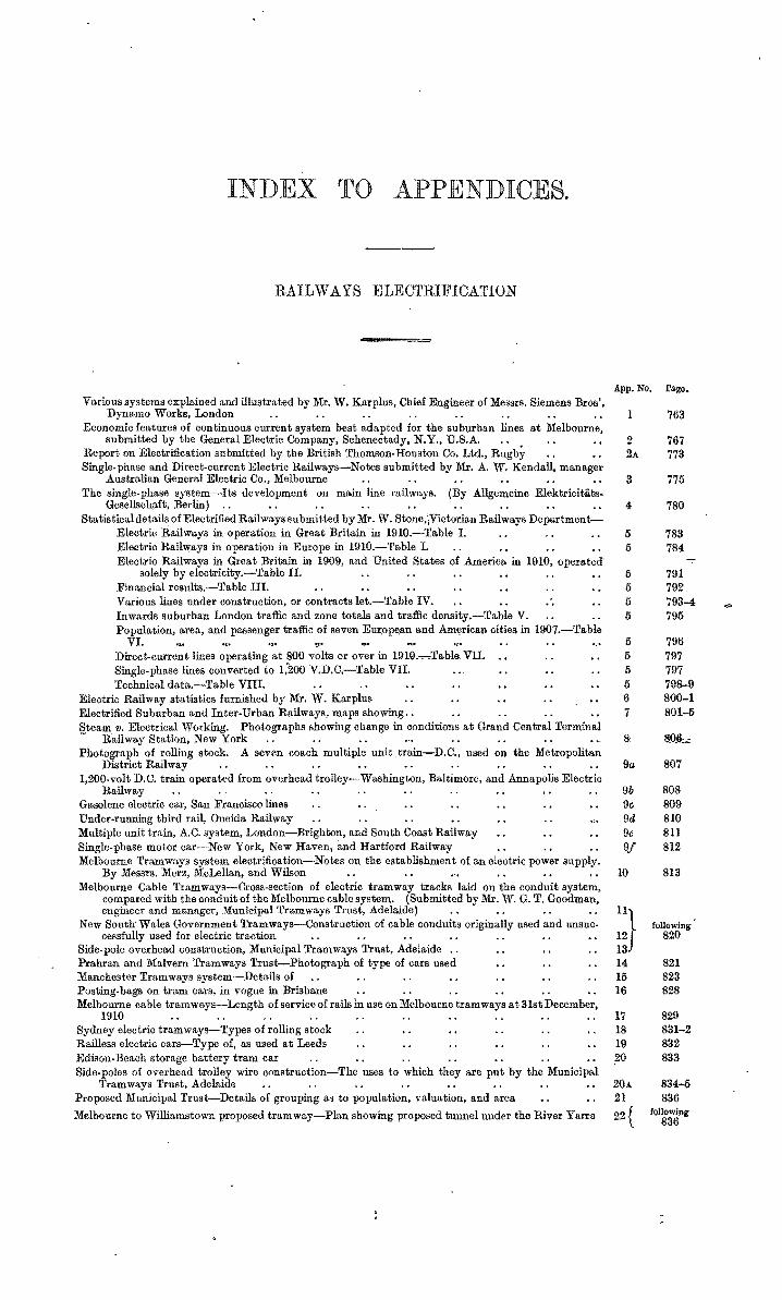
The D.C. Low Volt~tge System (iJOO, 550, 600, 750, and 800 volts) is almost exclusively adopted for tramway purposes-further, for city and partly f01· suburban rail ways, as elevated, underground~ t·ubes, and so on.
With tramways the overl1ead wire system (either trolley wheel or bow collector) is generally adopted for conveying the current to the motors of the cars. In several cities the conduit system (plough collector) is in use.
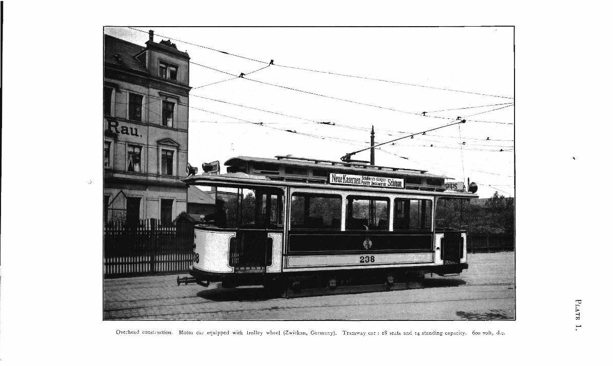
With elevated and underground rail ways, and with tubes, the third ~il sysLem with a special shoe for current collection-in some cases a fourth rail is used for carrying the current back to the power house-is largely adopted. For instance-
Overhead W.ire : Almost by all the electric tramways. Conduit System,: Vienna, Budapest, New "fork, London, and so on. Third Rail : Elev:a.ted and underground or tubes, Berlin, Budnpest, Hamburg, London,_
Newcastle-on-Tyne, and so on.
See also system mentioned under " F."
(See Plates l, 2, and 3, following page 765.)
2. 'fhe D.C. Higlt Voltage S;11stem.
-:I: he D.C. High Voltage System (I ,000, I ,200, I ,500, and 2,000 volts) is frequently adopted for 'high-speed inter-urban tramways C<•nnecting two distant towns, and for heavy traffic purposes.
The third rail is only in use for voltag,es up to 1,000 volts (with the exception of oue line in America where the third rail is nsed for 1,200 volts) ; for IJigher voltagcs the o1•erhead line construction is generally adopted-t.hat is, the normal tramway suspension for slow speed and the catenary system for higher speeds (in lhe latter case the bow collector is mostly in use) .
.for instan(le-Indianopolis~Louisville Tramway Co. ( i ,200 ''olts), Chicago-MillwaukeeRailway, Wengeralp Railway (Switzerland), i\fnifieres Sniut Marie, and so on.
(See }'late 4, following page 765.)
3. The Combined D.C. Low Voltage-Iliglb Volta,qe System, · The Combined D.C. Low Voltage-High Voltage Systetu is often adopted for long extensions of
existing low voltage tramways, and where it is desirable to. run the cars of an inter-urban high voltage railway or tramway on the lines of an exist.iug low voltage tramway. This system is further in use where for some reason or other the voltage has t.o be lowered in certnin places as, for instance, in stations, tunnels, and so on.
For instance-Frankfort.-on-the-1\fain, Cologne-Boun Ruilway, Pittsburg-Newcastle, and so on.
(See Plate 5, followin:s page 765.)
(B) THE SINGLE PHAI:iE ALTERN.ATlVI<: CUHRKl\T SYSTEM (KNOWN AS A.C. SYSTEM).
J·. The A·.G. Low Volta~e S,stem.
The A.C. :tow Voltage System (250; 300, 550 volts) is prlllcinally iu use for short tramways,, especially for mining purposes, where the current has to be tu ken fmm an existing power plant, Only· overP,eaJ. wire is in use. \
For instance-Tramway St. Avoid (750 volts), Mulheimer Bergwerksveri:n (250 yolts);, Kirch bichl in Tyrol (150 volts), and so on,

0
764
2. 1'he A.C. High Voltage System.
The A.C. High Voltage System ( 4,000 up to 20,000 volts) is principally adopted for long-distance high-speetl railways with heavy traffic ln these. instances, only overhead wire with catenary suspen~~on and bow collector is in use, both in connexion with locom (tives, as well as with. motor car~ (multiple t{nit system).
The frequency of the A.C. is usually 15, 16, or 25 cycles per second for high voltage railways, and in isolated cases 50 cycles for tramways. ·
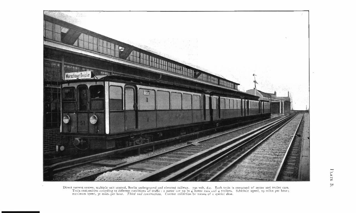
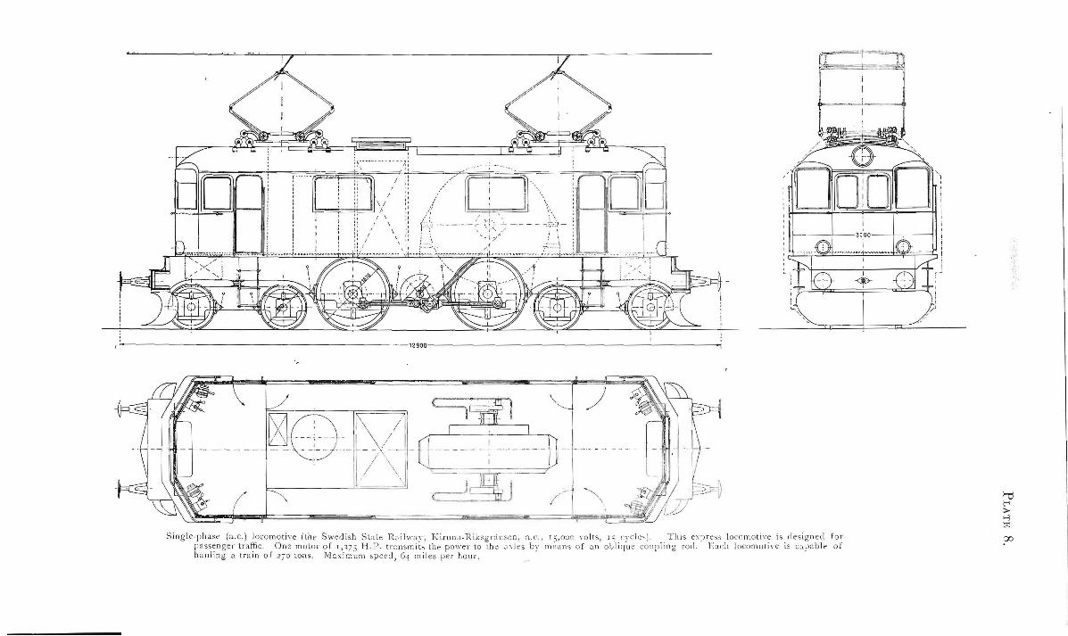
For instance-Prussian State Railways, Rotterdam-Hague, London-Brighton, LaucasterHeysham-Morecambe (Midland Railway), Kiruna Ricksgt·ansen, Visalia-Exeter-Lemon Cove (America), and so on.
(See Plates 6, 7, 8, 9, 10, following page 765.)
3. The Combined A. C. Low Voltage-High Voltage System.
The Combined A.C. Low Voltage-High Voltage System is applied to tramway or railway systems where the outer or long-distance lines are operated on A. C. high voltage (catenary trolley wire suspension), and where in the inner area of the towns or in the stations the tramways or rail ways have to be run on low voltages.
For instance-Railway in the Province of Parma, Roma-'Civita, Castellana, and so on.
(See Plate 11, following page 765.) 0
(C) Tn1c MIXED DmECT CunRENT-SrNGLE PHAsE SYsTEM (D.C.-A.C. SYSTJo;M).
1. 1'/le D. G. Low Voltage-A. C. Low Voltage S!Jstem.
The D.C. Low Voltage-A.C. Low Voltage System has, up to the present, uot come into use to large extent; the traffic t·eqnirements can almost always b3 met equally as well with the corn· bined D.C. Low Volt,age-High Voltage System for aborter distances as with· the mixeJ D.C.-Low V oltage-A.C. High Voltage i::iystem. (See below.)
For instance-Vienna-Baden, and so on.
0 (See Plate 12, following page 765.)
2. J'!.e JJ. C .. Low Voltage-A. C. Higlt Voltage System.
The D.C. Low Voltage-A.C. High Voltage System is used where two or more existing D.C. tramway systems are to be connected with each other by a long-distance high-speed railway, and
· where it is de!iirable that the same cars should be rnn both on the tramway and the railway track. For the D.C. part, overhead wire construction or third rail may be used, whereas only overhead
catenary trolley wire construction \vith bow collector is used for the A.C. part. For instance·-New York, New Haven, Hartford, and so on.
(D) THE THREE PHASE SYSTEM. The Three Phase System is only in very few places in use for tramway work, but had been adopted
before the development of the A.C. single-phase sy~tem, with especially good results for heavy goods traffic, where constant speed is required and when• always the same train density has to be dealt with (speed regulation being difficult). The advantages of the system are shown best when the trains have to be hauled over long iuclines ; power regeneration is then easily performed.
At least two overhead wires are t•equired to convey the electric current to the motors of the vehicles For instance-Low voltage tramway, L11gano (Switzerland); high voltage railway, Marien
felde-Zossen (nr;:ar· Berlin, l3L miles per hour attained); Simplon Railway, Cascade tunnel (Great Northern), and so on.
(See Plate 13, following page 765.)
(E) THE STORAGE-'!OATTERY SYSTE!II. This system has been practically abandoned for tramway purposes for years. Quite recently trials
were made on tramways with a new type of storage batteries. On the other hand, storage-battery cars are used to some extent in Europe on railways to deal with the suburban traffic on steam railway lines during slack hours. This system may be used on long lines wtih slack traffic where only one or two cars are run on the same line. No trolley wire or third rail construction is required.
For instauce·-Storage-battery cars of the Prussian State Railways, and so on.
(See Plate 14, following page 765.)
(F) THE TRACKLESS TRMlWAY SYSTEM.
This system is usually adopted only as forerunner of electric tramways, where the density of the traffic wo~ld not justify .the construction of a permanent track. This system does not allow high speeds, :and is not suitable for l!ealing with rush traffic; on the other hand, excellent had roads are required. A special trollPy wire. suspension constructir.n is adopted.
This system has been de\·eloped practically only for D.C. Low Voltage, and could therefore be ' .enumerated' as a subdivision of the system "A."
For instance-Adopted in several places in England, Austria, Germany, France, and so on.

765
For city and suburban railway lines, motor cars (multiple unit system) will generally be used advantageously for train propulsion, whereas locomotives would be advisable for long-distance railways and goods traffic.
The use of motor ears allows, economically, for very widely differing train compositions, each unit of which the train is made up carrying its own motors ; with motor cars a higher acceleration can be obtained, and, finally. the train could return to depot in the event of breakdown of one motor. On the other hand, locomotives would be· preferably adopted where trains of practically the same composition have to be deaJt with (to handle heavy trains at one time and light trains at another time would mean the hauling about of an·· unnecessary heavy weight of locomotive in the latter case). Snch locomotivee would .contain one or two large motors in their construction instead of a la1ger nnmber of smaller motors throughout the train, thus reducing the first cost. as well as the cost of supervision and maintenance. Furthermore, all passenger cars on the electric lines would be interchangeable with those of the steam lines.
Generally speaking, with the D.C. System the necessary provisions have to be made to limit the liability to electrolysis, and to interference with telephone, telegraph and signalling systems, both actions being effected by stray currents or leakage. On the ot.her hand, with the A.C. 8ystem there is no tendency to electrolysis, but the interference with the telephone, telegraph, and signalling systems is more severe, produced by leakage and inductance.
Comparing the different methods of eo.n veying the current to the motors of the vehicles, every system has undoubtedly its advantages and disadvantages. The adoption of one system or the other will therefore depend on local and traffic conditions, and on the voltage and the current eystem decided upon. For tramways either the Conduit System (underground) or the Overhead Trolley Wire System may be adopted. Fot· railways the Third Rail System may be chosen in connexion with D.C. Low Voltage System, whereas with the D.C. High Voltage or any A.C. System only the overhead wire suspension, most likely the catenary, would be adopted. But it has to be remembered that with the third rail system alterations <of the station platforms may be required, and witl1 the overhead wire system alterations of the station roofs, of tnnnels and bridges might be necessary.
'Vith regard to tramways, it is known that, the first cost of erection of the trackless system or the storage-battery system is least ; then again, the overhead wire construction is by far cheaper than the conduit system. The car equipment for D.C. is lighter and ehea.per than the A.C. equipment. Rega.rdmg the operar.ing cost it can safely be stated for tramways that the D.C. Low V6)ltage System with overhe~d wire construction and with cars running on rails is the cheapest generally.
With regard to railways, it is by far more difficult to outline the relative cost of erection and working <of the plant. But, generally speaking, it may be said that with the D.C. System the car equipments are lightet· and cheaper than w·ith the A.C System, whet·eas the equipment of the line is cheaper with the A.C. catenary wire suspension than with the D.C. third rail. At the same time, especially for longdistance railways, the feeders or transmission lines and the transformer station or substations are less ~xpensive with the A.C. !'\ystem than with the D.U. System. The power required in the power-house for both systems may be taken as being approximately eqtial.
It is trne t;hat the A.C. Motor req1,1ires more power than the D. C. Motor, due to the higher weight <of the A. C. equipment, but, on the other hand·, the energy losses during the starting period of the D.C. Motor (there !tre no ;;tarting l,•sses with the A. C. Motor), and the losses in the substations, and in the D.C. trolley wire or third rail transmission, are by far higher than the los~es in the A.C. transfonner stations and the A.C. high voltage trolley and transmission line. The maintenance of the A.C. equipment is perhaps a litrle more expensive than that of the D.C" equipment, but this item is fully counterbalanced, especially for long-distance railways, by the higher working and maintenance cost of the D.C. substation.~ :against the A. C. t.ransformer stations, where no attendance is needed and where practically no maintenance is required.
Thus it will be seen that it is very hard to discuss the advantages and disadvantages of the ·different systems generally ; and that it is always best for any given problem to ascertain by thorough investigations, calculations, and comparison which of the systems mentioned above can be recommended. 'Then that system will have to be decided upon, which, for a period of several year::1 will show the best !lconomical results, considering not only the working expenses but also the interest on anti the paying off the first capital expenditnre !
But the decision on the system to be a!)optecl may often be influenced by other considerations. For instance, that it be desirable to rnn the same cars or trains on the tracks of another rail way already <operated eleetrically, that the railway shoulcl rtlll as tramways on streets of towns or villages to be crossed, that electric railways or tramways in operatiotl are to be connected, that existing electric power plants are to be considered, or that some local difficulties may prevent the adopt.ion of one system or the other, and eo on.
Assuming that none of the restrictions mentioned above have to be consider\'d, and that an absolutely independent milway has to be electrified, t.hen the different electric systems may fairly be compared under the same suppositions. Then, again, it will depend on the special conditions to be fulfilled which system will prove to be the most advan1ageous. It often happens that for certain suppositions one system shows distinct advantages over all the other systems, whereas when altering the conditions (for instance, the train density, the train composition, the length of linll, and so on) another system may tnrn out to be more economical.
It is therefore most essential in every individual casfl, where an existing railway has to be electrified or a new electric railway has to be built, to stipulate exactly in the best possible Wf1Y the conditions under which the railway has to be" operated. Then, of course, it is merely a matter of calculation which .system-has to be adopted.
The statements made above will probably explain to a certain extent the apparent conflict of opinions of different experts and writers, who pa1·tly ascertain that one system is the cheapest in first cost -of erecti<?n, maintenance, and working expense<~, whereas the other proves with the same conviction that the other system is cheaper and more economical. Both parties are undoubtedly right, but in every case it has to he investigated very earefully whether the special conditions of the two railways are really comparable. It is certainly '!bsolutely wrong to transfer the experi~;nce¥ gained wi.th one railway to any other rail way to one's liking. <
(See Plates 15 to 24, following page 765.) 16998. 3D

----------------
-Overhead construction. Motor car equipped with trolley wheel (Zwick;.m, Germany). T ramway car: r8 se<Lls and 14 standing capacity. 6oo volt, d.c.

Standard four-wheel car. Capacity : 18 seats and 14 standing. 6oo volt, d.c. Overhead w1re cOn'itruction. Bow c:>llector,
Di rect cu rrent system. multiple unit contro l, B e rlin underground and e levated railway. 750 vo lt , d. c. E ach tr'lin is composed of motor and trai ler cars. T rain composition according to di ff e rent condit ions of traffi c r moto r car up to 4 motor cars a nd 4 tra ilers. Schedu le sr._eed, 19 miles per hour; ma,imuon 'reed, JI miles per hour. Third rat! constructzon . C urrent co llection b,· means o f a spec ia l shoe.

PLATES 4 AND 5.
Direct cmrent loromol i1· ~ !Miner:1l Rail\\,1\ I onh· fnr hea1· freig-ht (MC!it.ihe,-S ,t int e M a rie). cl.r . , 2.ooo volt. J-:ach locom ot i,·e is equipped \\ith fnur n;:-> tcn :- of 1~ H.H.P. e:1 ch lde , io::n ed f o t 1.ono volt eadt ), and is c:1pable of hauling lrCl in- of 200 lo JO" ton' on .1 g r· client of r in 33· C'a tena n trolle' wire co nstruction. bow eo! I ectot.
Di rect current, 4-c ;~r trnin; multi p le unit control. Each train consists of 2 motor cars and I or 2 trailers. Passenger a nd g oods traffic (Cologne-Bon,n R a ilway ). d.c., r,ooo / 550 volt . Each motot car is equipped with 2 d .c. motors (r ,ooo volt) of 140 H . P . each. The same cars run in the v icinity of the towns of Cologne and Bonn ;~nd in these towns with d .c. 550 volts, and between Cologne and Bonn with d .c. r,ooo volts. The 3-car tra in h as a capacity cf r go passengers; the 4-car tra in has a capacity of 26o p assengers. The maximum running speed is 38 miles per hour; the maximum possible speed, so miles per hour. Catenary suspension of trolley wire, bow collector.

Singl e-JJha'e (.1.c.) locomotive (the P nt'>inn S Lttc R.tihYaY, De,s:ltt-Bi tte· feld) . a.c. ro,ooo volt-t ' < ' c le<. This expre'" locomotive is designed for pas,enger 1n dnc . One t ,>oo H.P. motor , w J, ich t r.. n~mit< the J'OII'l'f to the \\ hcrl< b.- mc·:,rh nf 'vne Yertical co upling rod. The average ]o,\d consist <; of a train o f 240 ton<, Dt :t spe rl o f 6o mi le, a n hour. !lf:t,inhlllt 'l't'erl , 66 m-]., , "' lro ur.

Single phase (a.c.) locomotive (''\'icscnthal Railway, a.c. Io,ooo volts, IS cycles). These locomotives are designed to deal with both Two 6oo h. p. motors, which transmit their power to the a-xles throu!!h two coupling rods displaced at nn angle of go deg. N' hand!in1,5 a ~oods trttin of 500 tons on a gradient Qf I in IOO. Maximum speed np to 6o mi]es aq hnl,lf·
nassenger and goods traffic. Each locomntive i> capabl.;
~~-- - ·· -¥- ~--- ,~:
\ 1 l1
I
\I ~;=:=;:,=!l~l\
i I
/
\
12 900--------------------------------------------------------------~
) -~I] - /''\_ ],-/ \ ----- -
S ing le -phase (a.c.) locomotive (lh e Swed rsh Sl.ile Ra lhl ay , K trUil d-l<.J k Sgl "l\Sen, "c, rs,noo \Olh, r :; C) Cle' ) TlliS e ' lness locomotive is design ed fo r passenger traffic. O ne motm of r,175 H .P. tr a nsm its th e power to the ,1\ks by mc,,ns of an o i, !J, luc coupl 1n g \Od E a ch locom o tive is capab le of h a u ling a tra in of 210 lons . Ma, im um speed, 64 miles per hour .
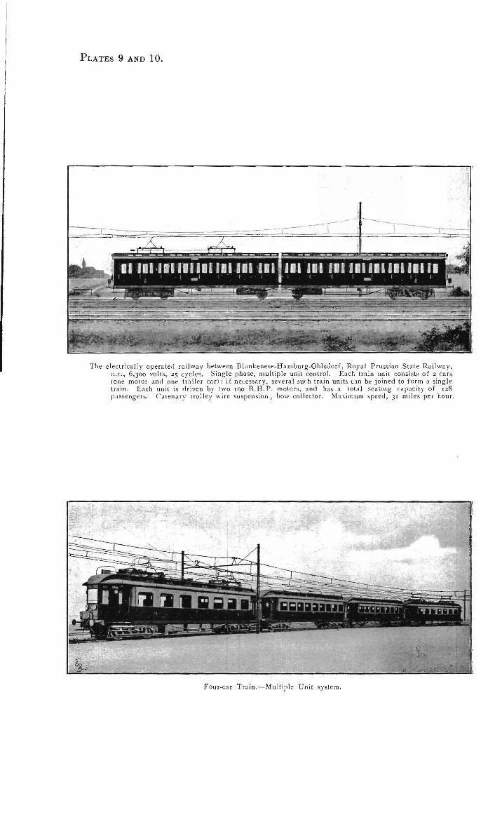
PLATES 9 AND 10.
T he elec t rica lly opera ted r a ilway between B lankenese-H amburg-Ohlsclorf, R oya l Prussian St a te R ailway. a. c. , 6,300 vo lts, 25 cyc les. S ing le phase, mult iple unit cont rol. E ach tra in un it consists of 2 cars (one motor and one tra iler car ); if necessn ry, severa l such train un it• can be j oined to f orm a s ing le t ra in . Each un it is d riven by two 190 B .H. P. motors, and ho, a tota l seat ing capaci ty of 128 passenge r!;. Ca tena ry tro lley "i re 'iuspens ion , bow collector. Ma\ imum speed, 31 m iles per hou r.
F our-ca r Train.-Multiple U n it system.

Single-rhase mo tor ca r, multiple unit svstem (Rotte rchm-I-l aag -Scheveninge" R ail wa y. a .c., ro,ooo Yolts, 25 cycles) . Each train consists normal ly of 2 moto r cars and 2 lr:~ il er c:n s. T otal sealin g- copac1ty_, 322 passenger:; E ach mo to r c:n 1s eq uipped with two motors of 190 H .P. each . The average speed is 38 mil e:; !'er hour. The m aximu m speed, 6o miles pe1 hour (and m ore).

,PLATE 10-a.

PLATE 11.
Sing le P ha ·e (:t .c.) M0to r Ca r. (The rai lway in the P rovi r.ce of l':tnna (l t.:t h ·) n. c. 4,oooj 400 volts , 1.) ··rcle!>. ) The n•o tor ca rs are J esigned to dea l with both passenger ;lnd goods tra ffi c . l~arh moto r c. lf is eq uipped with two ss· H . P . n.o to rs [4 ,000/ 40o ,·oJts--25 cycles] ; the ~ ;lllle c;~rs run in the vic inity of the town o f Pa rm a with a.c. a t 400 vo lts, a nd on the rem~ining section with a .c. a t 4,ooo vo lts. The heav iest. tra in consi>ts of one motor ca r and three t ra ile r ca rs, with a total sea ting ca pac it y of u_:;. }fa, imum speed: 1_:; miles pe r hour.

t'LATE · llA.

PLATES 12 ANn 13.
D. C". low vollage -n.c. low ,oltage system ; pn,senger l r.,ftic onl)·· (The electr ic n.c. -rl.c. rail" a'· \"ienna- Tiarlen I Austria) d.c. ·''0 ,·olts-n.r. 550 volt>. 1 ~ < nle,.) C.tch motor car i, P< jui pperl "ith fout motor, of 44 H.P. each (d.c. and a.r. 300 10lt). Trai n composition one moto r rnr and one 01 two t railers. The '<;tm e ea" run in the vicinit ·· of the to"'" of Vienna and B.tclen "ith rl.c .. and between th r"· to'"" "ill, .t.r Th e ma\ imum speed is 38 mile; pe t hour. Tr;~mwa \' trollev wire ' U'f>ension , bow collector.
•
T raih fo r hi6h-specd railwa,·. :VI.-ri~nfelrl e. Fossen thrPP- J•hase c urrent, ro,o.>o vo'l. 4S cvlk>. Motot ca r for his;hspeerl tests. E.1ch cor h.td been e ' JIIi pperl with four mo to r>, m ounted dirertl1· upon th ~ "' i' ing J.\les . The C(lr has a -;eating cap::tcih· for 50 p:tssenge r>. M.t\imum speed •< ltainerl IJO mil es per hour. Three 01·erhead wrres for C(lrry iug the current to the motors, special sup f;Orts provided on on~ side of the !rack. T hree bow co llectors being u>ed. Max in1u111 g radient : 1 in 200. Output elf the four moto r,; whe n running at a speed of 124 m iles pe r ho ur on a gradient of r in 200, a bout 2,200 H.P . or .'i)O H. P. each. (Ma~imum output of motors during startin ·• jleriods : ~. 2oo or 8oo H .P. for motor. ) Tesl ,; had been carried out ~ l so with t railers up to " tol:l l ll"eight of 200 ton ,;.

Pr.ATE 14.
The motor cars are d esigned for passenger traffic. Each unit t:onsi sts of two cars, both equipped wi th one motor of about 75 H .P . each. The storage battery consists.o f •68 ce lls, giving a running voltage of 300 volt s , the ce lls a re located in the lower front part of each ca r. The batte ry is designed for a run o f 62 miles with one cha rge , the schedule speed being 37 miles per hour . S uch cars a re run now on seve r:tl o f the Prussian S t.1tc Railways (for suburban service) during periods o f slack traffi c. [Cost in Germ:m y, :tbout £ s,ooo pe r C<l<. R ailway motor cars with storage batteri es.]
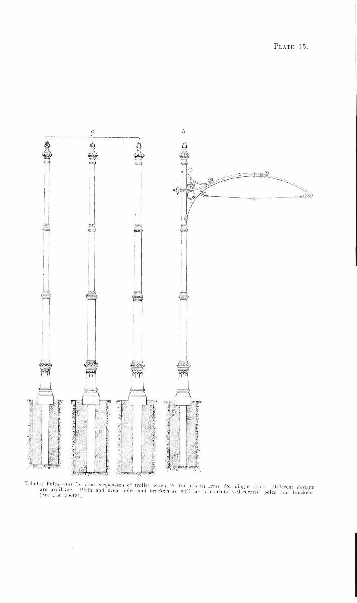
PLATE l5.
TubuLtr Pol e,.--(a ) for cros, suspelloion of trolk) wi re; lbJ f:Jr br~ · · ke t ., rm& fot ,i ng-le lr::tt;k D ifferent dc. igns .ue "'·a ilabk. Plllin and e1·en pole, and brackets ·'" well a, o rna menta l!, -decor.l!e.J poles nnd brackets. l ~ee Jbo pht•!o;.1
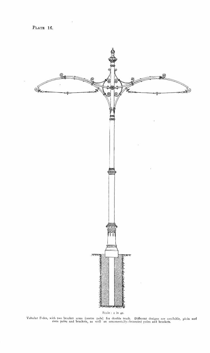
PLATE 16.
Scaie : r in 40.
Tubular Fc,Jes, with two bracket arms (centre pole) fo r double track. D ifferent designs are available, p la in and even poles and brackets, as well as ornnmenta lly. rlecoraled poles and brackets.

PL.iTE 17.
a b ,------A--------.
A B
Scale : r in 40.
L a!tice I ron Poles.-(a) f or cross suspension of trolley wire; (b) for bracket a rms, sin g le track. Diffe rent designs of c<~ps and br.1 cl<ets a re available. Chea1•ec than tubul a r poles; migh t be used in outer d istricts.

• " PE.NilE:' 18.
Sc4le : 1 in 40.
Lattice Iron Poles, with two bracket arms (centre poles) for doub le track . Different designs of caps and bracketo are available. Cheaper th an tubular poles; might be used in outer di stricts .

COMPARISON between Overhead Wire Construction for Bow Collector and Overhead Wire Construction for Trolley Wheel.
Example of two plants actually carried out with approximately the same conditions of tracks, i.e. : DRESDEN with Bow Collector (at the left of drawing). BERLIN with Trolley Wheel (at the right of drawing).
DRAWING A. Length of Span Wires Point of Suspension Trolley W ire Suspensions Frogs and CrossiiJO"s
Bow Collector,
130 yards. 3 poles. 12 clips,
Trolley Wheel.
190 ·yards. 5 poles and 4 rosettes. 28 clips. 6 - 1
- and 4 - -2.-trogs crosstngs
DERLlN. (Jbulla•r de~ GllochiDI!f'o IUldPr~)
·-~ ' -·

I I
/
/ I
! /
~V I ' /
/
/ /
I ' I
PnATt<: 20•
.,;
" 0 0..
.... B u
" 0 u

Cologne (on the Rhine, Germany) double track. Centre poles wi th doub l.- bracket arms. Tubular poles fo r the combined use to support trolley wire and a re la mps for street lighting; bow collector.

F rnnkfo rt on the :.1,tin !Germany) dorrb le t rn.ck. Cross s spension of overhead wires f or bow collector. T ubular poles combined with the post for a rc la mps Ornamenl'a l poles, arran gt!ment on bridge, pol es not interfering with traffic .
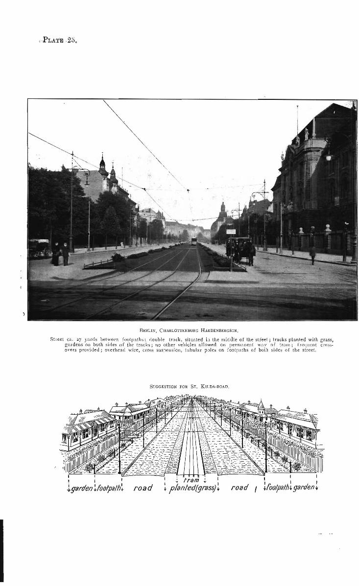
fl;;RLIN, (HARLOTTENBURG HARDENBERGSTR.
Street en. 27 yards between footpaths; doub le track , situated i.1 the lllidd ie of the street; tracks planted with grass, ga rdens on lxlth sides of the tracks; no other vehicles allowed on perm ;lnent "'''-" of trolll; freq uent c rosso,·ers provided; overhead wire, c ross suspension, tubular p)les on foot p;lths of bolh s ides of the street.
S~JGGESTION FOR ST. KILDA-ROAD.
1 j I
l garden ~footpath~ road 1 : ram ' 1
~ pianled(g:.0ss)~ road 1 I I I 1 I I ~foo!path• garden-+-
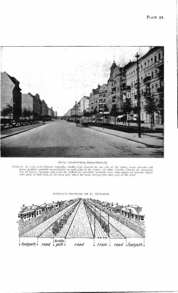
PLATE 2:1.
JJer!in , C ha rlottenburg Bismarchkslrafse.
S treet ea 40 1a rd, w1de be tl\ een footpath> , double t r. tck situ.tt t d on one ~i de of tlte 'treet; tr;lcks pl.tnted " ith gras>; g.trden> provided symmetrically on both ,ides of rh~ street: no other 1t'h1c le> a llo"ecl on permanen t \\ il)' of trams; frey nent uos>·O\'e rs for ped estrians p rovided; 01·erhend wirt>, cross snspen,ion bet'><een tubnl :u stee l poles on both side> of the t rnck only abo,e the t rack, len ,·ing free other part of the <t reel
At TF.IC\ \ rt n : Sr.;GGES'IION FOR ST. Ku D .-1-RO.-ID.
I I I I
+ footpath -l-•bridle' I I
road +path-~- road I I
l tram 1 I
I I
road lfootpath ~