appendix 1. figures. - federal aviation...
TRANSCRIPT

9/30/2008 AC 150/5340-30D Appendix 1
111
APPENDIX 1. FIGURES.
AC 150/5340-30D 9/30/2008 Appendix 1
112
2.1.NO
TES
:
3.In
stal
l yel
low
runw
ay e
dge
light
s on
the
last
200
0 ft.
or
one-
half,
whi
chev
er is
less
, of a
n in
stru
men
t run
way
.
Whi
te li
ghts
will
be
show
n as
bla
ck.
Lege
nd fo
r Fig
ures
2-2
2 an
d G
ener
al N
otes
4.P
avem
ent m
arki
ngs
are
show
n on
the
draw
ing
in th
is
AC
for r
efer
ence
onl
y. A
C 1
50/5
340-
1 de
scrib
es th
e de
taile
d m
arki
ng s
peci
ficat
ions
.
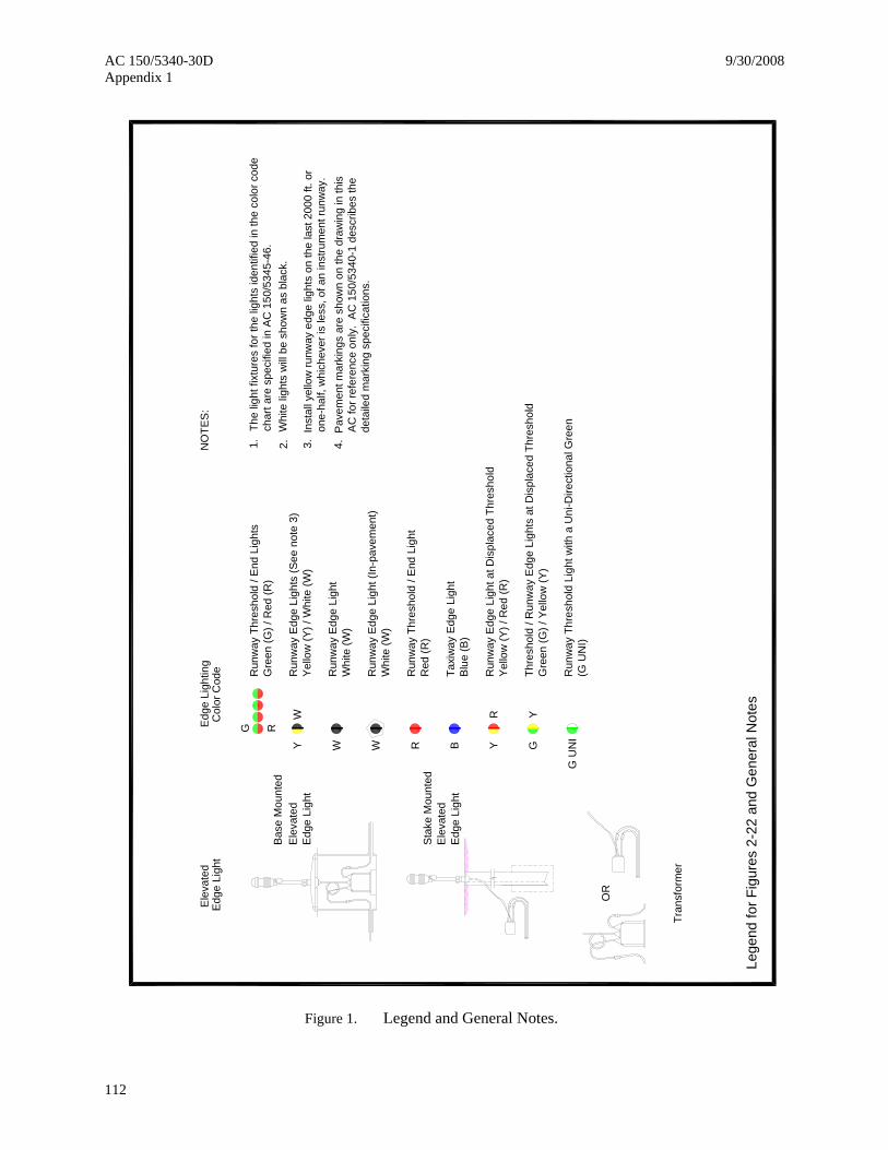
Edg
e Li
ghtin
gC
olor
Cod
e Run
way
Thr
esho
ld /
End
Lig
hts
Run
way
Edg
e Li
ghts
(See
not
e 3)
Run
way
Edg
e Li
ght (
In-p
avem
ent)
Run
way
Thr
esho
ld /
End
Lig
ht
Taxi
way
Edg
e Li
ght
Run
way
Edg
e Li
ght a
t Dis
plac
ed T
hres
hold
Thre
shol
d / R
unw
ay E
dge
Ligh
ts a
t Dis
plac
ed T
hres
hold
Ele
vate
dE
dge
Ligh
t
Gre
en (G
) / R
ed (R
)
Yel
low
(Y) /
Whi
te (W
)
Whi
te (W
)
Blu
e (B
)
Yel
low
(Y) /
Red
(R)
Gre
en (G
) / Y
ello
w (Y
)
Red
(R)
Run
way
Edg
e Li
ght
Whi
te (W
)
The
light
fixt
ures
for t
he li
ghts
iden
tifie
d in
the
colo
r cod
e ch
art a
re s
peci
fied
in A
C 1
50/5
345-
46.
Bas
e M
ount
ed
Sta
ke M
ount
edE
leva
ted
Edg
e Li
ght
Ele
vate
dE
dge
Ligh
t
OR
Tran
sfor
mer
YW
W R B YR
GY
W
RG
Run
way
Thr
esho
ld L
ight
with
a U
ni-D
irect
iona
l Gre
en
G U
NI
(G U
NI)
Figure 1. Legend and General Notes.
9/30/2008 AC 150/5340-30D Appendix 1
113
200'
max
200'
max
200'
max
400'
max
Thre
shol
d / R
unw
ay E
nd L
ight
sIn
stal
led
with
LIR
L's
or M
IRL'
s
2' m
in10
' max
DET
AIL
A
DE
TAIL
A:
taxi
way
10'
ctr t
o ct
r
ctr t
o ct
r10
'
200'
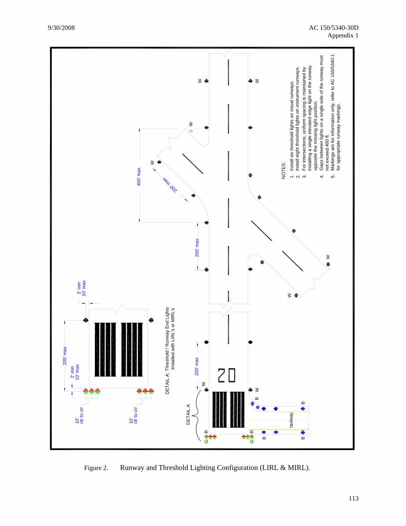
max 1.In
stal
l six
thre
shol
d lig
hts
on v
isua
l run
way
s.2. 3.
For i
nter
sect
ions
, uni
form
spa
cing
is m
aint
aine
d by
in
stal
ling
a si
ngle
ele
vate
d ed
ge li
ght o
n th
e ru
nway
op
posi
te th
e m
issi
ng li
ght p
ositi
on.
4.G
aps
betw
een
light
s on
a s
ingl
e si
de o
f the
runw
ay m
ust
not e
xcee
d 40
0 ft.
NO
TES
:
Inst
all e
ight
thre
shol
d lig
hts
on in
stru
men
t run
way
s.
WW
W
W
Mar
king
s ar
e fo
r inf
orm
atio
n on
ly, r
efer
to A
C 1
50/5
340-
1 fo
r app
ropr
iate
runw
ay m
arki
ngs.
5.
W
W
W
W
BBB
B
2' m
in10
' max
G
R
G
R
Figure 2. Runway and Threshold Lighting Configuration (LIRL & MIRL).
AC 150/5340-30D 9/30/2008 Appendix 1
114
200'
max
200'
max
200'
max
runw
ay
taxi
way
ctr t
o ct
r10
'
Inst
alle
d w
ith H
IRL'
sTh
resh
old
/ Run
way
End
Lig
hts
DE
TAIL
A:
DE
TAIL
A
2' m
in10
' max
ctr t
o ct
r10
'
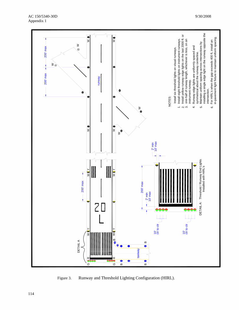
For H
IRL'
s w
hen
the
gap
exce
eds
400
ft, in
stal
l an
in-p
avem
ent l
ight
fixt
ure
to m
aint
ain
unifo
rm s
paci
ng.
Mai
ntai
n un
iform
spa
cing
acr
oss
inte
rsec
tions
by
inst
allin
g a
sing
le e
dge
light
on
the
runw
ay o
ppos
ite th
e in
ters
ectio
n.
Inst
all y
ello
w ru
nway
edg
e lig
hts
on th
e la
st 2
000
ft. o
r on
e-ha
lf of
runw
ay le
ngth
, whi
chev
er is
less
, on
an
inst
rum
ent r
unw
ay.
Run
way
edg
e lig
hts
are
unifo
rmly
spa
ced
and
sym
met
rical
abo
ut th
e ru
nway
cen
terli
ne.
Inst
all e
ight
thre
shol
d lig
hts
on in
stru
men
t run
way
s.In
stal
l six
thre
shol
d lig
hts
on v
isua
l run
way
s.1. 2. 3. 4. 5. 6.N
OTE
S:
W
W
W
W
200'
max
2' m
in10
' max
W
Y
W
Y
W
Y
W
YG
R
G
R
B
B
BB
WW
WW
Figure 3. Runway and Threshold Lighting Configuration (HIRL).

9/30/2008 AC 150/5340-30D Appendix 1
115
200'
max
200'
max
Take
off S
tart La
ndin
g Th
resh
old
The
pave
men
t pre
cedi
ng th
e ru
nway
thre
shol
d is
usa
ble
pave
men
t, bu
t is
not p
art o
f the
des
igna
ted
runw
ay.
NO
TES:
1.
B
B
B
BB
G
R
G
R
W
Y
W
Y
Spac
e ta
xi e
dge
light
s pe
r par
agra
ph 2
.1.3
.
This
con
figur
atio
n fo
r run
way
alig
ned
taxi
way
will
not b
e ap
prov
ed
for n
ew c
onst
ruct
ion.
2. 3.
Figure 4. Runway with Taxiway at End.

AC 150/5340-30D 9/30/2008 Appendix 1
116
NO
TES
:1.
200'
max
10' m
ax
The
pave
men
t prio
r to
the
runw
ay th
resh
old
is n
ot in
tend
ed
for a
ircra
ft us
e.
Inst
all e
ight
thre
shol
d lig
hts
on in
stru
men
t run
way
s.In
stal
l six
thre
shol
d lig
hts
on v
isua
l run
way
s.2. 3.
Figure 5. Runway with Blast Pad (No Traffic).

9/30/2008 AC 150/5340-30D Appendix 1
117
LDA
Sto
p E
nd
Land
ing
Thre
shol
d
Take
off S
tart
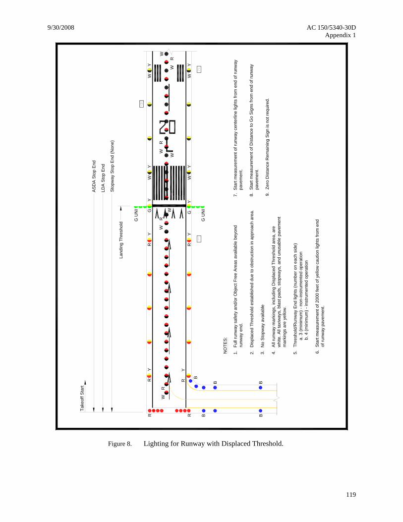
3.G
Y
2.NO
TES:
1.Fu
ll ru
nway
saf
ety
and
obje
ct fr
ee a
reas
ava
ilabl
e be
yond
runw
ay e
nd.
Dis
plac
ed th
resh
old
esta
blis
hed
due
to o
bstru
ctio
n in
app
roac
h ar
ea.
All m
arki
ngs
mus
t com
ply
with
the
stan
dard
s sp
ecifi
ed in
AC
150
/534
0-1.
W
Y
W
Y
W
Y
W
Y
G U
NI G
Y
G U
NI
R
Y
R
Y
R
Y
R
Y
B
B
B
BBRR
Figure 6. Lighting for Runway with Displaced Threshold.
AC 150/5340-30D 9/30/2008 Appendix 1
118
Land
ing
Thre
shol
d
WY
WY
GR
GR
B
B BB
200'
max
NO
TES
:
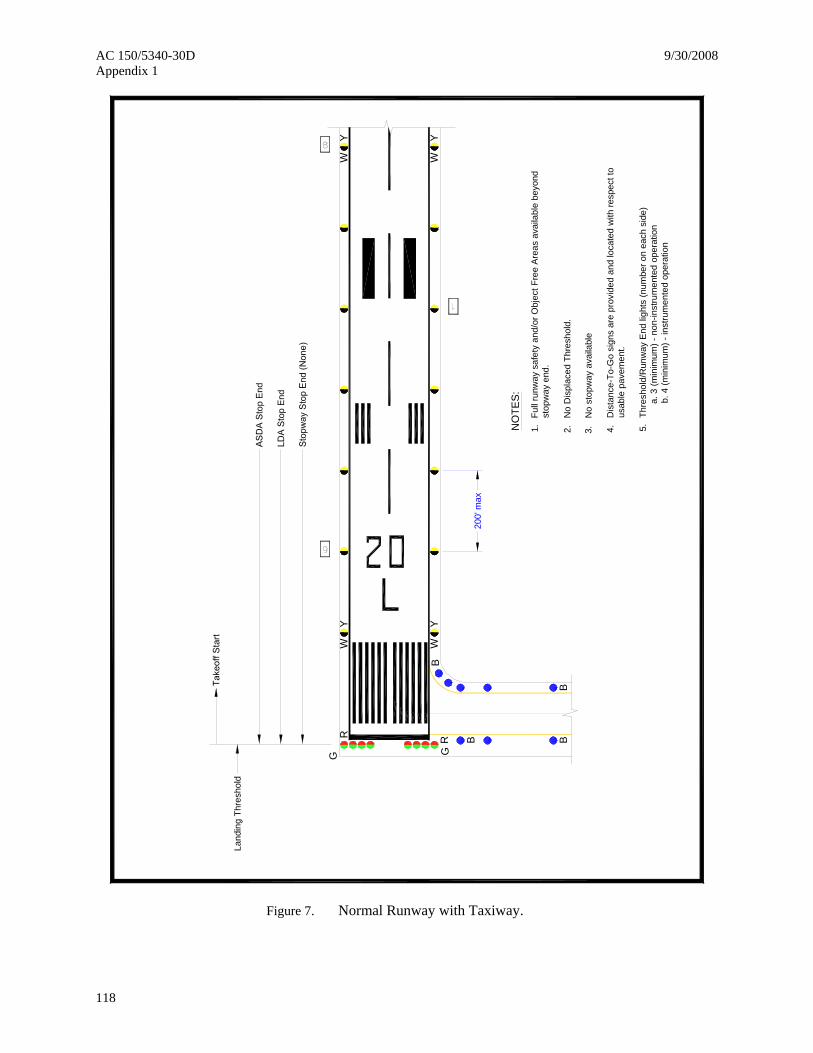
1.Fu
ll ru
nway
saf
ety
and/
or O
bjec
t Fre
e A
reas
ava
ilabl
e be
yond
stop
way
end
.
No
Dis
plac
ed T
hres
hold
.
4. 5.
Dis
tanc
e-To
-Go
sign
s ar
e pr
ovid
ed a
nd lo
cate
d w
ith re
spec
t to
Thre
shol
d/R
unw
ay E
nd li
ghts
(num
ber o
n ea
ch s
ide)
a. 3
(min
imum
) - n
on-in
stru
men
ted
oper
atio
nb.
4 (m
inim
um) -
inst
rum
ente
d op
erat
ion
usab
le p
avem
ent.
2.
No
stop
way
ava
ilabl
e3.
WY
WY
Figure 7. Normal Runway with Taxiway.
9/30/2008 AC 150/5340-30D Appendix 1
119
Take
off S
tart
G
Y
W
Y
W
Y
W
Y
G U
NI G
Y
G U
NI
R
Y
R
Y
R
Y
R
Y
B
B
B
BBRR
NO
TES
:
1.
All
runw
ay m
arki
ngs,
incl
udin
g D
ispl
aced
Thr
esho
ld a
rea,
are
whi
te. A
ll ta
xiw
ays,
bla
st p
ads,
sto
pway
s, a
nd u
nusa
ble
pave
men
t
Full
runw
ay s
afet
y an
d/or
Obj
ect F
ree
Are
as a
vaila
ble
beyo
ndru
nway
end
.
Dis
plac
ed T
hres
hold
est
ablis
hed
due
to o
bstru
ctio
n in
app
roac
h ar
ea.
4.
mar
king
s ar
e ye
llow
.
5.Th
resh
old/
Run
way
End
ligh
ts (n
umbe
r on
each
sid
e)a.
3 (m
inim
um) -
non
-inst
rum
ente
d op
erat
ion
b. 4
(min
imum
) - in
stru
men
ted
oper
atio
n
2.
No
Sto
pway
ava
ilabl
e3.
Sto
pway
Sto
p E
nd (N
one)
ASD
A St
op E
nd
LDA
Sto
p E
nd
Land
ing
Thre
shol
d
9.
6.S
tart
mea
sure
men
t of 2
000
feet
of y
ello
w c
autio
n lig
hts
from
end
Zero
Dis
tanc
e R
emai
ning
Sig
n is
not
requ
ired.
of ru
nway
pav
emen
t.
7.S
tart
mea
sure
men
t of r
unw
ay c
ente
rline
ligh
ts fr
om e
nd o
f run
way
pave
men
t.
8.S
tart
mea
sure
men
t of D
ista
nce
to G
o S
igns
from
end
of r
unw
aypa
vem
ent.
W
R
W
R
W
R
W
Y
WW
W
R
W
Figure 8. Lighting for Runway with Displaced Threshold.

AC 150/5340-30D 9/30/2008 Appendix 1
120
4.NO
TES
:
3.
No
Stop
way
ava
ilabl
e.
2.1.A
ll ru
nway
mar
king
s, in
clud
ing
Dis
plac
ed T
hres
hold
are
a, a
re w
hite
.A
ll ta
xiw
ays,
bla
st p
ads,
sto
pway
s, a
nd u
nusa
ble
pave
men
t
Full
runw
ay s
afet
y an
d/or
Obj
ect F
ree
Are
as a
vaila
ble
beyo
nd
AS
DA/
LDA,
but
not
bey
ond
runw
ay e
nd.
Dis
plac
ed T
hres
hold
est
ablis
hed
to p
rovi
de fu
ll ru
nway
saf
ety
and/
or o
bjec
t fre
e ar
eas
prio
r to
thre
shol
d.
mar
king
s ar
e ye
llow
.
AS
DA
Stop
End
Take
off S
tart
LDA
Sto
p En
d
Sto
pway
End
(Non
e)
End
of U
sabl
e P
avem
ent
YG
YR
BB
B
B
YR
R R
Land
ing
Thre
shol
d G U
NI
YG
G U
NI
W
RW
RW
WR
5.Th
resh
old/
Run
way
End
ligh
ts (n
umbe
r on
each
sid
e)a.
3 (m
inim
um) -
non
-inst
rum
ente
d op
erat
ion
b. 4
(min
imum
) - in
stru
men
ted
oper
atio
n
9.
6.S
tart
mea
sure
men
t of 2
000
feet
of y
ello
w c
autio
n lig
hts
from
end
Zero
Dis
tanc
e R
emai
ning
Sig
n is
not
requ
ired.
of ru
nway
pav
emen
t.
7.S
tart
mea
sure
men
t of r
unw
ay c
ente
rline
ligh
ts fr
om e
nd o
f run
way
pave
men
t.
8.S
tart
mea
sure
men
t of D
ista
nce
to G
o S
igns
from
end
of r
unw
aypa
vem
ent.
R R
Figure 9. Lighting for Runway with Displaced Threshold/Usable Pavement.
9/30/2008 AC 150/5340-30D Appendix 1
121
LDA
Stop
End
Dis
plac
ed T
hres
hold
Take
off S
tart B
B
BB
RR
RR
YY
GG
YY
WW
YY
WW
YY
ASD
A S
top
End
G U
NI
G U
NI
NO
TES
:
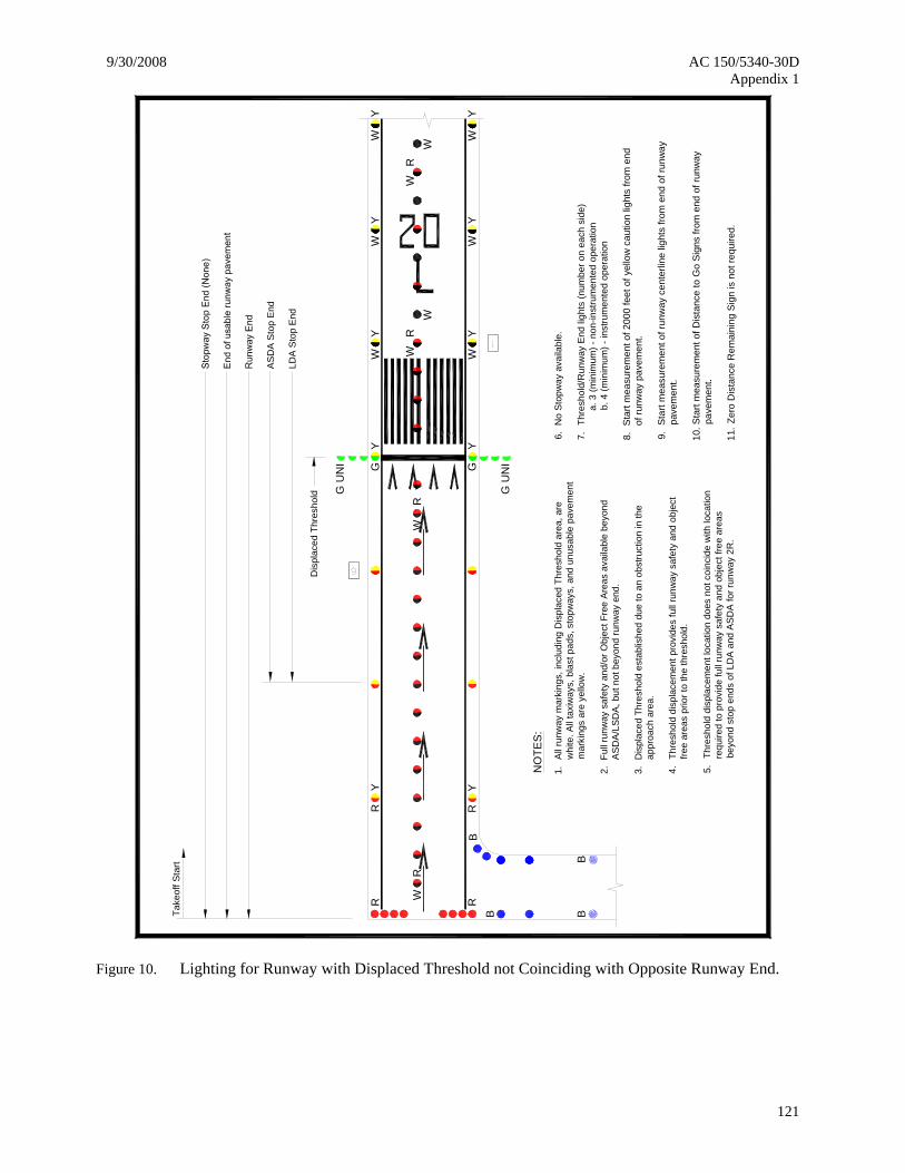
3.2.1.A
ll ru
nway
mar
king
s, in
clud
ing
Dis
plac
ed T
hres
hold
are
a, a
rew
hite
. All
taxi
way
s, b
last
pad
s, s
topw
ays,
and
unu
sabl
e pa
vem
ent
Full
runw
ay s
afet
y an
d/or
Obj
ect F
ree
Area
s av
aila
ble
beyo
ndA
SDA
/LS
DA,
but
not
bey
ond
runw
ay e
nd.
Dis
plac
ed T
hres
hold
est
ablis
hed
due
to a
n ob
stru
ctio
n in
the
4.Th
resh
old
disp
lace
men
t pro
vide
s fu
ll ru
nway
saf
ety
and
obje
ct
free
area
s pr
ior t
o th
e th
resh
old.
mar
king
s ar
e ye
llow
.
appr
oach
are
a.
7.6.N
o St
opw
ay a
vaila
ble.
Thre
shol
d/R
unw
ay E
nd li
ghts
(num
ber o
n ea
ch s
ide)
a. 3
(min
imum
) - n
on-in
stru
men
ted
oper
atio
nb.
4 (m
inim
um) -
inst
rum
ente
d op
erat
ion
5.Th
resh
old
disp
lace
men
t loc
atio
n do
es n
ot c
oinc
ide
with
loca
tion
requ
ired
to p
rovi
de fu
ll ru
nway
saf
ety
and
obje
ct fr
ee a
reas
beyo
nd s
top
ends
of L
DA
and
ASD
A fo
r run
way
2R
.
WW
RW
WR
WY
WY
11.
8.S
tart
mea
sure
men
t of 2
000
feet
of y
ello
w c
autio
n lig
hts
from
end
Zero
Dis
tanc
e R
emai
ning
Sig
n is
not
requ
ired.
of ru
nway
pav
emen
t.
9.S
tart
mea
sure
men
t of r
unw
ay c
ente
rline
ligh
ts fr
om e
nd o
f run
way
pave
men
t.
10.S
tart
mea
sure
men
t of D
ista
nce
to G
o S
igns
from
end
of r
unw
aypa
vem
ent.
WR
WR
Figure 10. Lighting for Runway with Displaced Threshold not Coinciding with Opposite Runway End.
AC 150/5340-30D 9/30/2008 Appendix 1
122
NO
TES
:
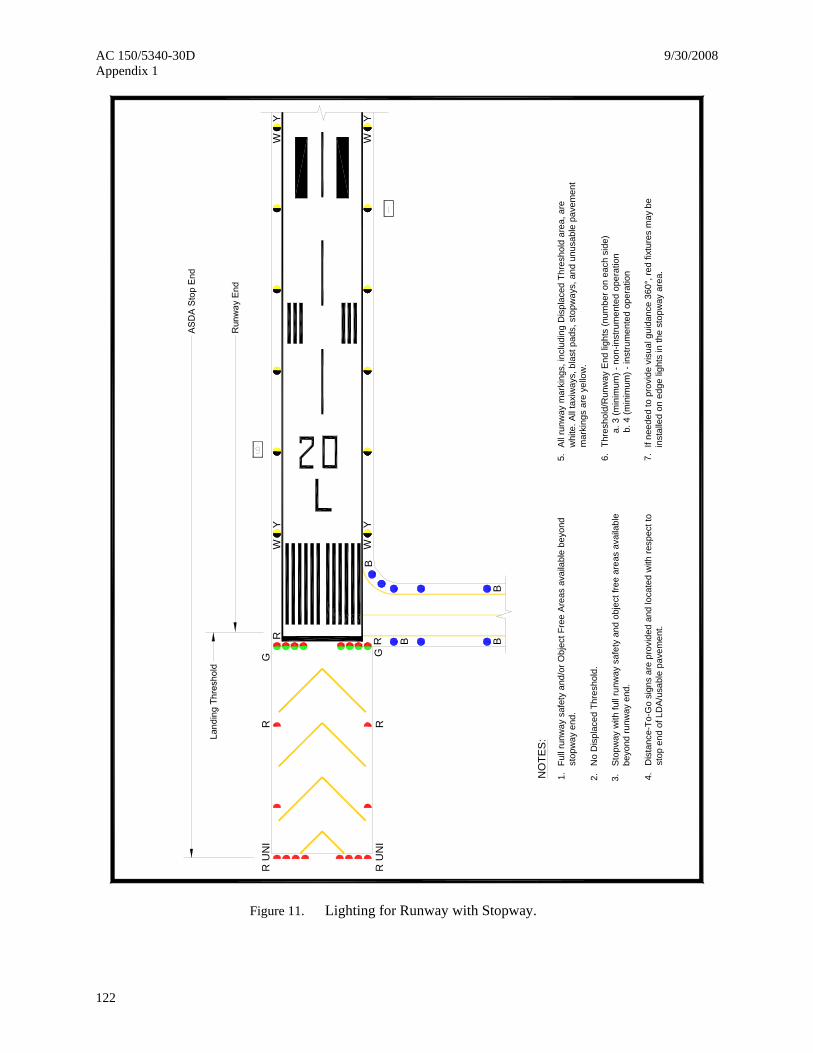
1.Al
l run
way
mar
king
s, in
clud
ing
Dis
plac
ed T
hres
hold
are
a, a
rew
hite
. All
taxi
way
s, b
last
pad
s, s
topw
ays,
and
unu
sabl
e pa
vem
ent
Full
runw
ay s
afet
y an
d/or
Obj
ect F
ree
Area
s av
aila
ble
beyo
ndst
opw
ay e
nd.
No
Dis
plac
ed T
hres
hold
.
4.
mar
king
s ar
e ye
llow
.
6.5.
Dis
tanc
e-To
-Go
sign
s ar
e pr
ovid
ed a
nd lo
cate
d w
ith re
spec
t to
Thre
shol
d/R
unw
ay E
nd li
ghts
(num
ber o
n ea
ch s
ide)
a. 3
(min
imum
) - n
on-in
stru
men
ted
oper
atio
nb.
4 (m
inim
um) -
inst
rum
ente
d op
erat
ion
stop
end
of L
DA/
usab
le p
avem
ent.
2.
Stop
way
with
full
runw
ay s
afet
y an
d ob
ject
free
are
as a
vaila
ble
3.be
yond
runw
ay e
nd.
If ne
eded
to p
rovi
de v
isua
l gui
danc
e 36
0°, r
ed fi
xtur
es m
ay b
e 7.
inst
alle
d on
edg
e lig
hts
in th
e st
opw
ay a
rea.
WY
WY
GR
GR
B
B BB
RR
UN
I
RR
UN
I
WY
WY
Figure 11. Lighting for Runway with Stopway.
9/30/2008 AC 150/5340-30D Appendix 1
123
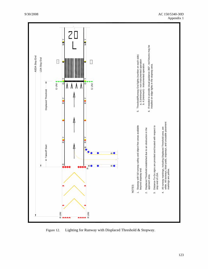
Dis
plac
ed T
hres
hold
BB
BB
Dis
plac
ed T
hres
hold
est
ablis
hed
due
to a
n ob
stru
ctio
n in
the
appr
oach
are
a.
NO
TES
:
1.
All
runw
ay m
arki
ngs,
incl
udin
g D
ispl
aced
Thr
esho
ld a
rea,
are
whi
te. A
ll ta
xiw
ays,
bla
st p
ads,
sto
pway
s, a
nd u
nusa
ble
pave
men
t 4.
mar
king
s ar
e ye
llow
.
6.5.
Dis
tanc
e-To
-Go
sign
s ar
e pr
ovid
ed a
nd lo
cate
d w
ith re
spec
t to
Thre
shol
d/R
unw
ay E
nd li
ghts
(num
ber o
n ea
ch s
ide)
a. 3
(min
imum
) - n
on-in
stru
men
ted
oper
atio
nb.
4 (m
inim
um) -
inst
rum
ente
d op
erat
ion
stop
end
of L
DA.
2.
Sto
pway
with
full
runw
ay s
afet
y an
d ob
ject
free
are
as a
vaila
ble
3.
beyo
nd s
topw
ay e
nd.
If ne
eded
to p
rovi
de v
isua
l gui
danc
e 36
0°, r
ed fi
xtur
es m
ay b
e in
stal
led
on e
dge
light
s in
the
stop
way
are
a.
RY
RY
RY
RY
GY
GY
R
R
G U
NI
G U
NI
WY
WY
R U
NI
R U
NI
Take
off S
tart
Figure 12. Lighting for Runway with Displaced Threshold & Stopway.
AC 150/5340-30D 9/30/2008 Appendix 1
124
50' m
ax
NO
TES
:1.
B
B
B
B
G
R
G
R
W
Y
W
Y
2.A
ll ru
nway
mar
king
s, in
clud
ing
Dis
plac
ed T
hres
hold
are
a, a
rew
hite
. All
taxi
way
s, b
last
pad
s, s
topw
ays,
and
unu
sabl
e pa
vem
ent
mar
king
s ar
e ye
llow
.
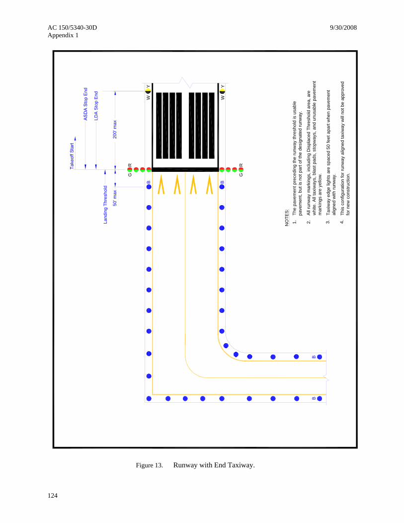
The
pave
men
t pre
cedi
ng th
e ru
nway
thre
shol
d is
usa
ble
pave
men
t, bu
t is
not p
art o
f the
des
igna
ted
runw
ay.
Land
ing
Thre
shol
d
LDA
Sto
p En
d
200'
max
Taxi
way
edg
e lig
hts
are
spac
ed 5
0 fe
et a
part
whe
n pa
vem
ent
alig
ned
with
runw
ay.
3.
This
con
figur
atio
n fo
r run
way
alig
ned
taxi
way
will
not b
e ap
prov
edfo
r new
con
stru
ctio
n.4.
Figure 13. Runway with End Taxiway.
9/30/2008 AC 150/5340-30D Appendix 1
125
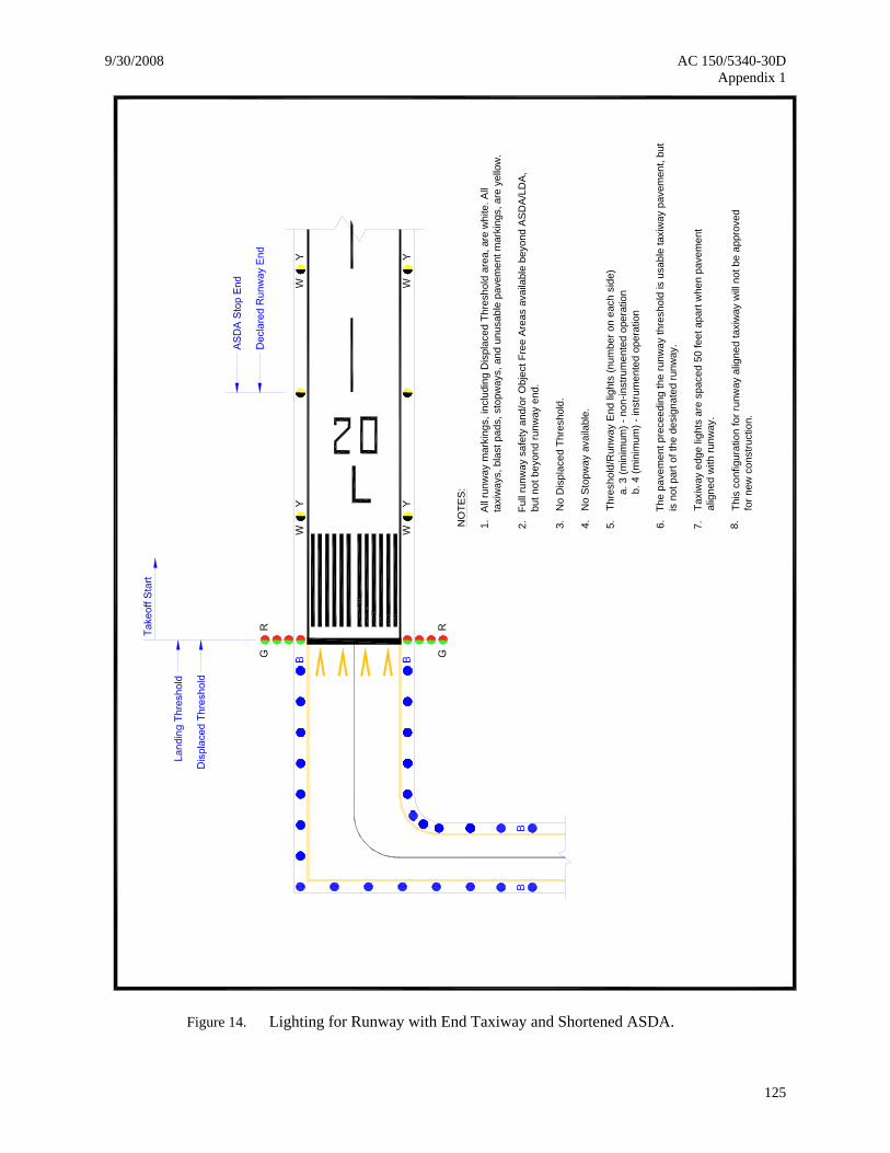
5.4.NO
TES
:
3.
No
Sto
pway
ava
ilabl
e.
2.1.A
ll ru
nway
mar
king
s, in
clud
ing
Dis
plac
ed T
hres
hold
are
a, a
re w
hite
. All
taxi
way
s, b
last
pad
s, s
topw
ays,
and
unu
sabl
e pa
vem
ent m
arki
ngs,
are
yel
low
.
Full
runw
ay s
afet
y an
d/or
Obj
ect F
ree
Are
as a
vaila
ble
beyo
nd A
SDA
/LD
A,bu
t not
bey
ond
runw
ay e
nd.
No
Dis
plac
ed T
hres
hold
.
Thre
shol
d/R
unw
ay E
nd li
ghts
(num
ber o
n ea
ch s
ide)
a. 3
(min
imum
) - n
on-in
stru
men
ted
oper
atio
nb.
4 (m
inim
um) -
inst
rum
ente
d op
erat
ion
6.Th
e pa
vem
ent p
rece
edin
g th
e ru
nway
thre
shol
d is
usa
ble
taxi
way
pav
emen
t, bu
tis
not
par
t of t
he d
esig
nate
d ru
nway
.
Taxi
way
edg
e lig
hts
are
spac
ed 5
0 fe
et a
part
whe
n pa
vem
ent
alig
ned
with
runw
ay.
7.
This
con
figur
atio
n fo
r run
way
alig
ned
taxi
way
will
not
be
appr
oved
for n
ew c
onst
ruct
ion.
8.
Figure 14. Lighting for Runway with End Taxiway and Shortened ASDA.
AC 150/5340-30D 9/30/2008 Appendix 1
126
Taxi
way
edg
e lig
hts
are
spac
ed 5
0 fe
et a
part
whe
n pa
vem
ent
alig
ned
with
runw
ay.
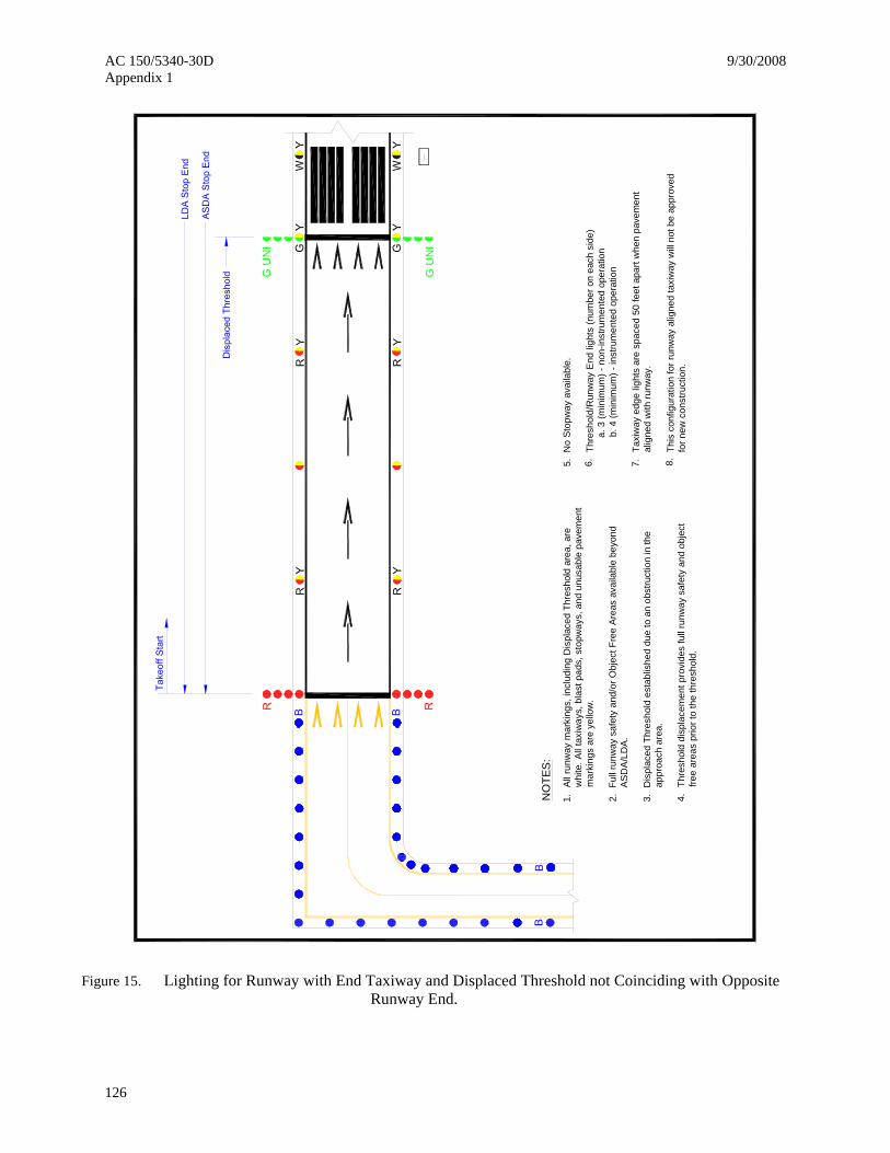
7.
NO
TES
:
3.2.1.A
ll ru
nway
mar
king
s, in
clud
ing
Dis
plac
ed T
hres
hold
are
a, a
rew
hite
. All
taxi
way
s, b
last
pad
s, s
topw
ays,
and
unu
sabl
e pa
vem
ent
Full
runw
ay s
afet
y an
d/or
Obj
ect F
ree
Are
as a
vaila
ble
beyo
ndA
SD
A/L
DA
.
Dis
plac
ed T
hres
hold
est
ablis
hed
due
to a
n ob
stru
ctio
n in
the
4.Th
resh
old
disp
lace
men
t pro
vide
s fu
ll ru
nway
saf
ety
and
obje
ct
free
area
s pr
ior t
o th
e th
resh
old.
mar
king
s ar
e ye
llow
.
appr
oach
are
a.
6.5.N
o S
topw
ay a
vaila
ble.
Thre
shol
d/R
unw
ay E
nd li
ghts
(num
ber o
n ea
ch s
ide)
a. 3
(min
imum
) - n
on-in
stru
men
ted
oper
atio
nb.
4 (m
inim
um) -
inst
rum
ente
d op
erat
ion
BB
G U
NI
G U
NI
BB
This
con
figur
atio
n fo
r run
way
alig
ned
taxi
way
will
not b
e ap
prov
edfo
r new
con
stru
ctio
n.8.
Figure 15. Lighting for Runway with End Taxiway and Displaced Threshold not Coinciding with Opposite Runway End.
9/30/2008 AC 150/5340-30D Appendix 1
127
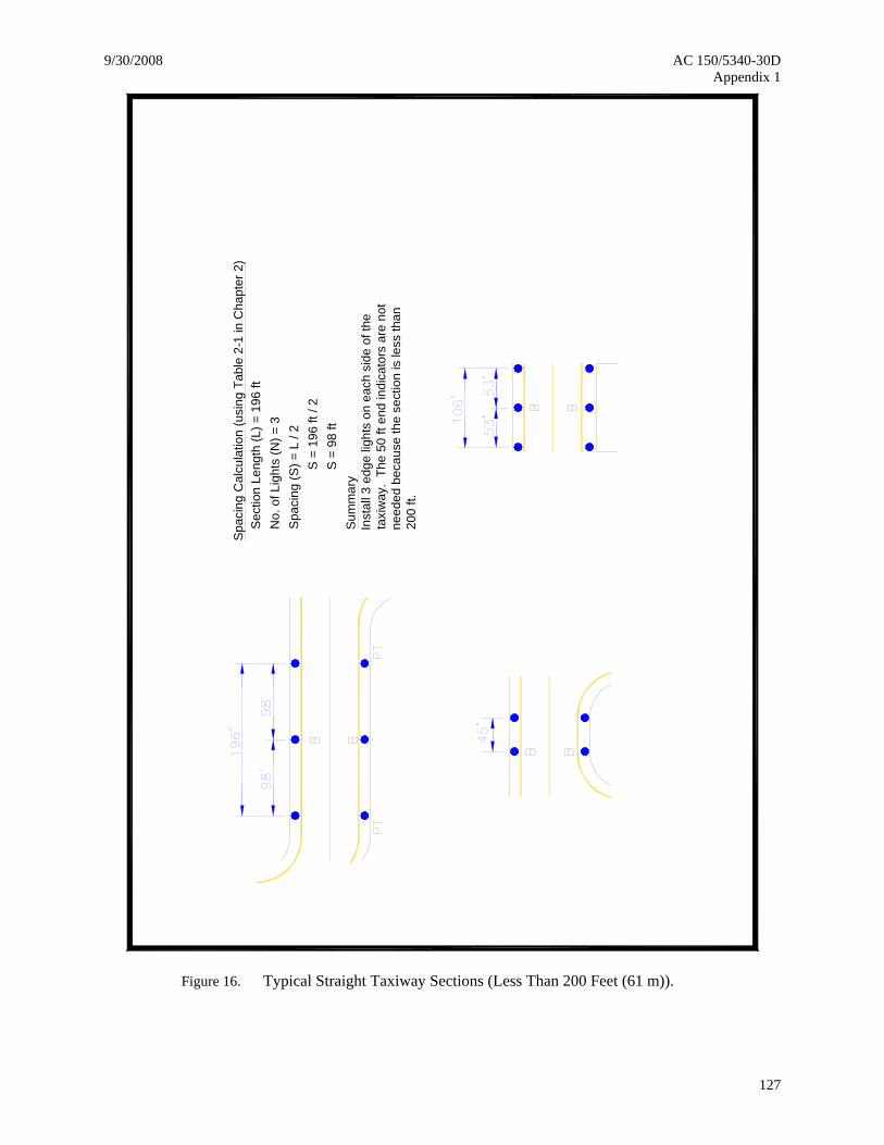
Spa
cing
Cal
cula
tion
(usi
ng T
able
2-1
in C
hapt
er 2
)
Sum
mar
yIn
stal
l 3 e
dge
light
s on
eac
h si
de o
f the
ta
xiw
ay.
The
50 ft
end
indi
cato
rs a
re n
ot
need
ed b
ecau
se th
e se
ctio
n is
less
than
20
0 ft.
Spa
cing
(S) =
L /
2N
o. o
f Lig
hts
(N) =
3S
ectio
n Le
ngth
(L) =
196
ft
S
= 1
96 ft
/ 2
S
= 9
8 ft
Figure 16. Typical Straight Taxiway Sections (Less Than 200 Feet (61 m)).
AC 150/5340-30D 9/30/2008 Appendix 1
128
NO
TES:
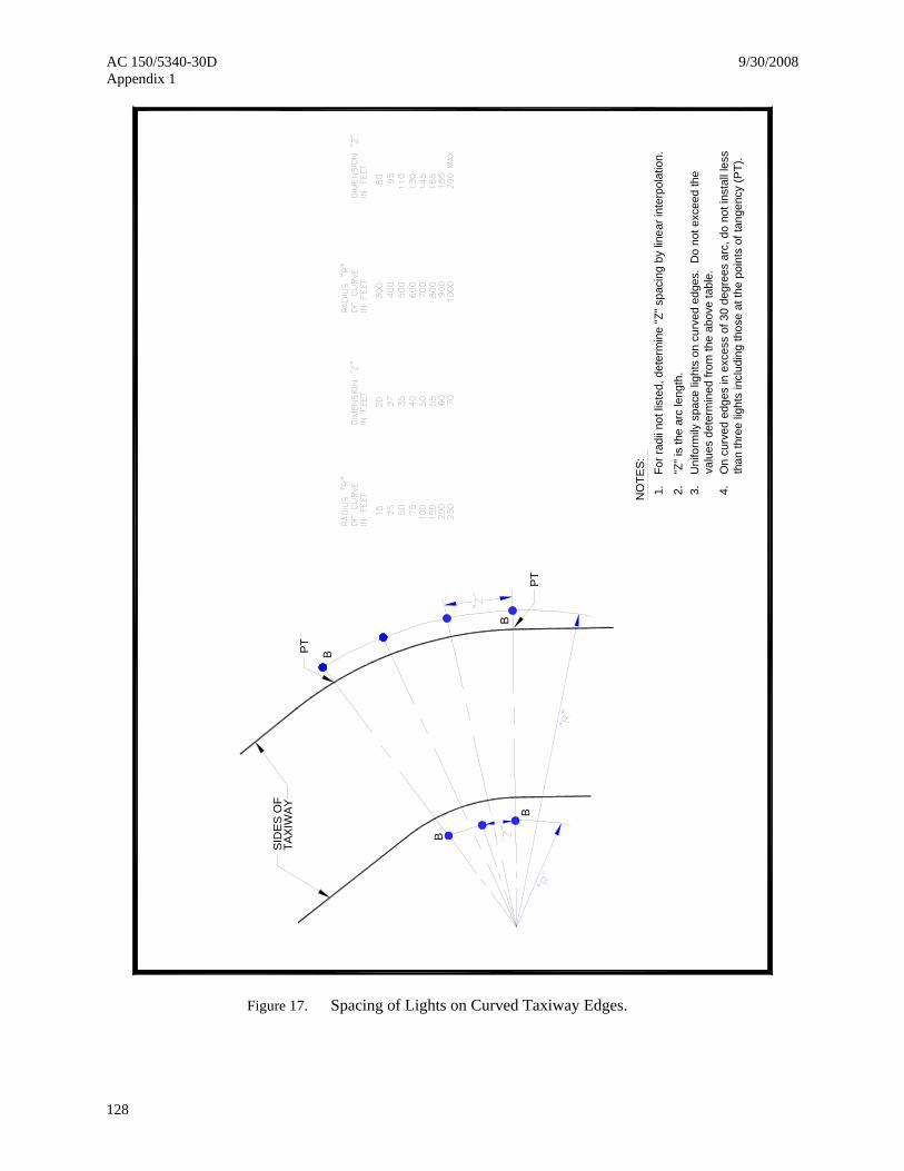
1.Fo
r rad
ii no
t lis
ted,
det
erm
ine
"Z" s
paci
ng b
y lin
ear i
nter
pola
tion.
2."Z
" is
the
arc
leng
th.
SID
ES
OF
TAX
IWAY
PT
PT
Uni
form
ily s
pace
ligh
ts o
n cu
rved
edg
es.
Do
not e
xcee
d th
e va
lues
det
erm
ined
from
the
abov
e ta
ble.
3. 4.O
n cu
rved
edg
es in
exc
ess
of 3
0 de
gree
s ar
c, d
o no
t ins
tall
less
th
an th
ree
light
s in
clud
ing
thos
e at
the
poin
ts o
f tan
genc
y (P
T).
B
B
B
B
Figure 17. Spacing of Lights on Curved Taxiway Edges.
9/30/2008 AC 150/5340-30D Appendix 1
129
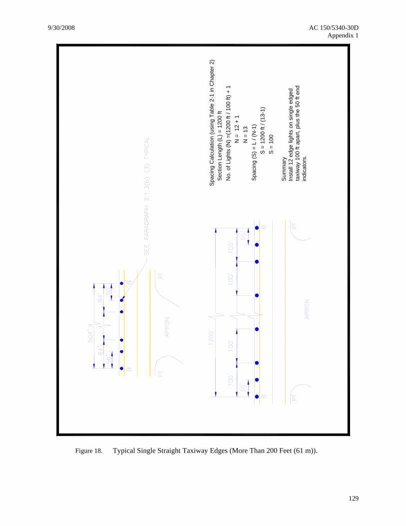
Spa
cing
Cal
cula
tion
(usi
ng T
able
2-1
in C
hapt
er 2
)
Sum
mar
yIn
stal
l 12
edge
ligh
ts o
n si
ngle
edg
ed
taxi
way
100
ft a
part,
plu
s th
e 50
ft e
nd
indi
cato
rs.
Spac
ing
(S) =
L /
(N-1
)
N =
12
+ 1
N =
13
No.
of L
ight
s (N
) =(1
200
ft / 1
00 ft
) + 1
Sect
ion
Leng
th (L
) = 1
200
ft
S
= 1
200
ft / (
13-1
)
S =
100
Figure 18. Typical Single Straight Taxiway Edges (More Than 200 Feet (61 m)).
AC 150/5340-30D 9/30/2008 Appendix 1
130
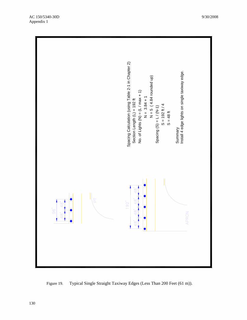
Spac
ing
Cal
cula
tion
(usi
ng T
able
2-1
in C
hapt
er 2
)
Sum
mar
yIn
stal
l 4 e
dge
light
s on
sin
gle
taxi
way
edg
e.
Spa
cing
(S) =
L /
(N-1
)
N =
3.8
4 +
1
N
= 5
( 4
.84
roun
ded
up)
No.
of L
ight
s (N
) = (L
/ m
ax +
1)
Sect
ion
Leng
th (L
) = 1
92 ft
S
= 1
92 ft
/ 4
S
= 4
8 ft
Figure 19. Typical Single Straight Taxiway Edges (Less Than 200 Feet (61 m)).
9/30/2008 AC 150/5340-30D Appendix 1
131
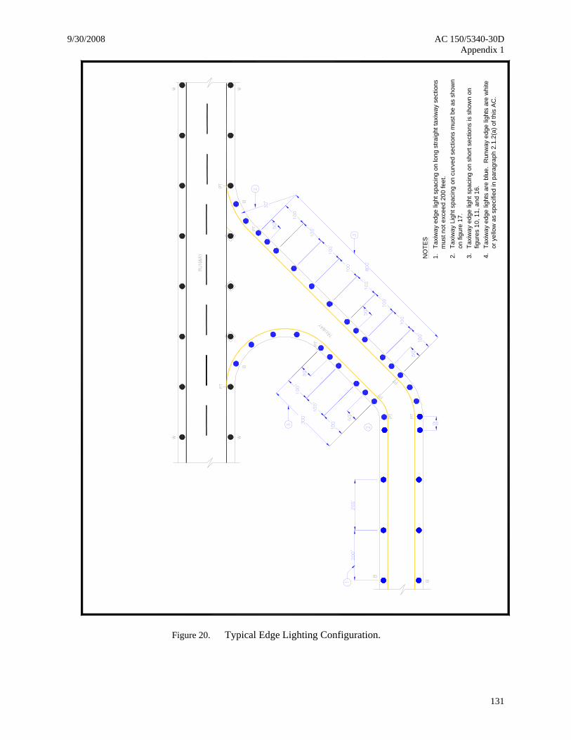
Taxi
way
edg
e lig
ht s
paci
ng o
n lo
ng s
traig
ht ta
xiw
ay s
ectio
ns
mus
t not
exc
eed
200
feet
.
Taxi
way
edg
e lig
ht s
paci
ng o
n sh
ort s
ectio
ns is
sho
wn
on
figur
es 1
0, 1
1, a
nd 1
6.
Taxi
way
Lig
ht s
paci
ng o
n cu
rved
sec
tions
mus
t be
as s
how
n on
figu
re 1
7.
1. 3.2.NO
TES
Taxi
way
edg
e lig
hts
are
blue
. R
unw
ay e
dge
light
s ar
e w
hite
or
yel
low
as
spec
ified
in p
arag
raph
2.1
.2(a
) of t
his
AC
.4.
Figure 20. Typical Edge Lighting Configuration.
AC 150/5340-30D 9/30/2008 Appendix 1
132
PT
PT
RU
NW
AY
PT
PT
PT
PT
Taxi
way
Taxi
way
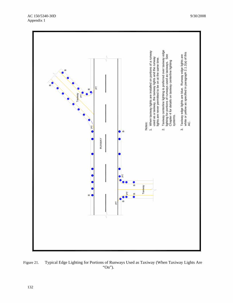
Not
es:
Whe
n ta
xiw
ay li
ghts
are
inst
alle
d on
por
tions
of a
runw
ay
used
as
a ta
xiw
ay, t
he ta
xiw
ay li
ghts
and
the
runw
ay
light
s ar
e ne
ver p
erm
itted
to b
e on
at t
he s
ame
time.
1. 2.Ta
xiw
ay c
ente
rline
ligh
ting
is p
refe
rred
ove
r tax
iway
edg
e lig
htin
g fo
r por
tions
of r
unw
ays
used
as
taxi
way
s. S
ee
Cha
pter
4 fo
r det
ails
on
taxi
way
cen
terli
ne li
ghtin
g sy
stem
s.
3.Ta
xiw
ay e
dge
light
s ar
e bl
ue.
Run
way
edg
e lig
hts
are
whi
te o
r yel
low
as
spec
ified
in p
arag
raph
2.1
.2(a
) of t
his
AC
.
BB
BB
BB
B
B
Figure 21. Typical Edge Lighting for Portions of Runways Used as Taxiway (When Taxiway Lights Are “On”).
9/30/2008 AC 150/5340-30D Appendix 1
133
PT
PT
RU
NW
AY
PT
PT
PT
PT
Taxi
way
Taxi
way
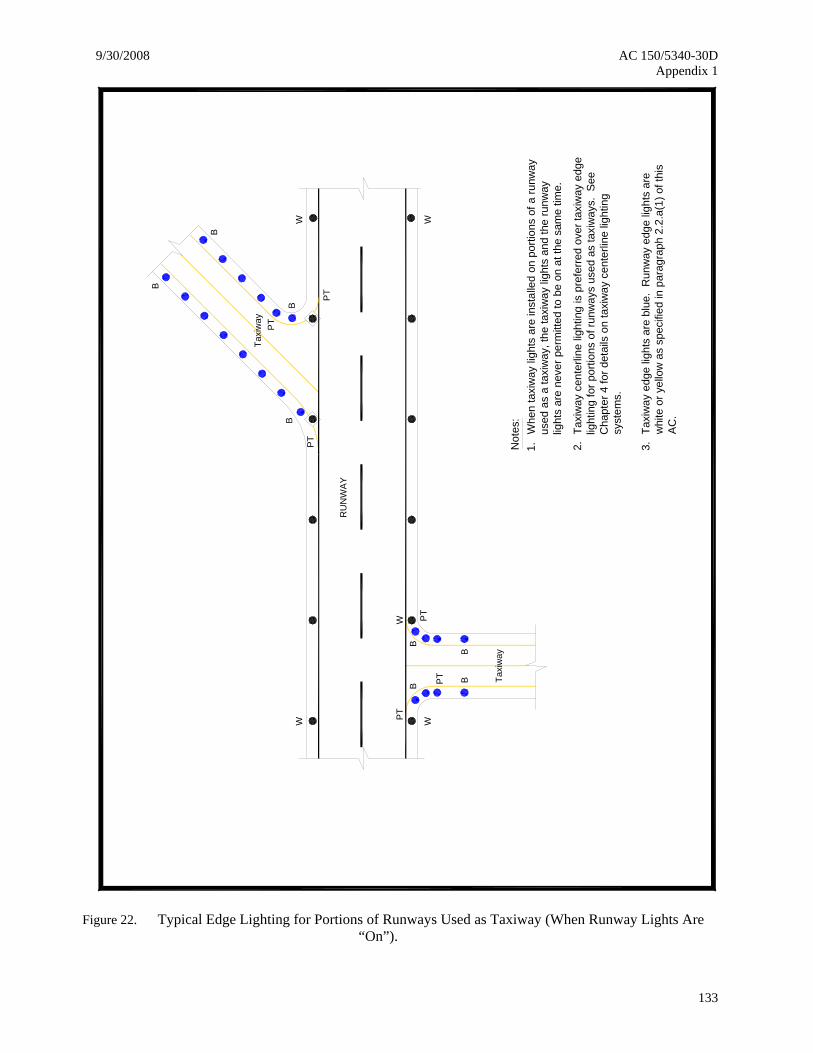
Not
es:
Whe
n ta
xiw
ay li
ghts
are
inst
alle
d on
por
tions
of a
runw
ay
used
as
a ta
xiw
ay, t
he ta
xiw
ay li
ghts
and
the
runw
ay
light
s ar
e ne
ver p
erm
itted
to b
e on
at t
he s
ame
time.
1. 2.Ta
xiw
ay c
ente
rline
ligh
ting
is p
refe
rred
over
taxi
way
edg
e lig
htin
g fo
r por
tions
of r
unw
ays
used
as
taxi
way
s. S
ee
Cha
pter
4 fo
r det
ails
on
taxi
way
cen
terli
ne li
ghtin
g sy
stem
s.
3.Ta
xiw
ay e
dge
light
s ar
e bl
ue.
Run
way
edg
e lig
hts
are
whi
te o
r yel
low
as
spec
ified
in p
arag
raph
2.2
.a(1
) of t
his
AC
.
W
B
B
B
B
W
W WB
B
BB
W
Figure 22. Typical Edge Lighting for Portions of Runways Used as Taxiway (When Runway Lights Are “On”).
AC 150/5340-30D 9/30/2008 Appendix 1
134
CO
NC
RE
TE A
NC
HO
R
RE
CO
MM
EN
DED
6"x
6"x1
2"
BAS
E M
OU
NTE
D, S
ER
IES
CIR
CU
IT
4" C
ON
CR
ETE
BA
CKF
ILL
(typ)
1/C
, 5KV
,
L-82
3 C
ON
NE
CTO
R
14" (
typ)
FRA
NG
IBLE
CO
UP
LIN
GA
ND
DIS
CO
NN
EC
T P
LUG
10" (min)
NU
MB
ER
TAG
NU
MB
ER
TA
G
12"
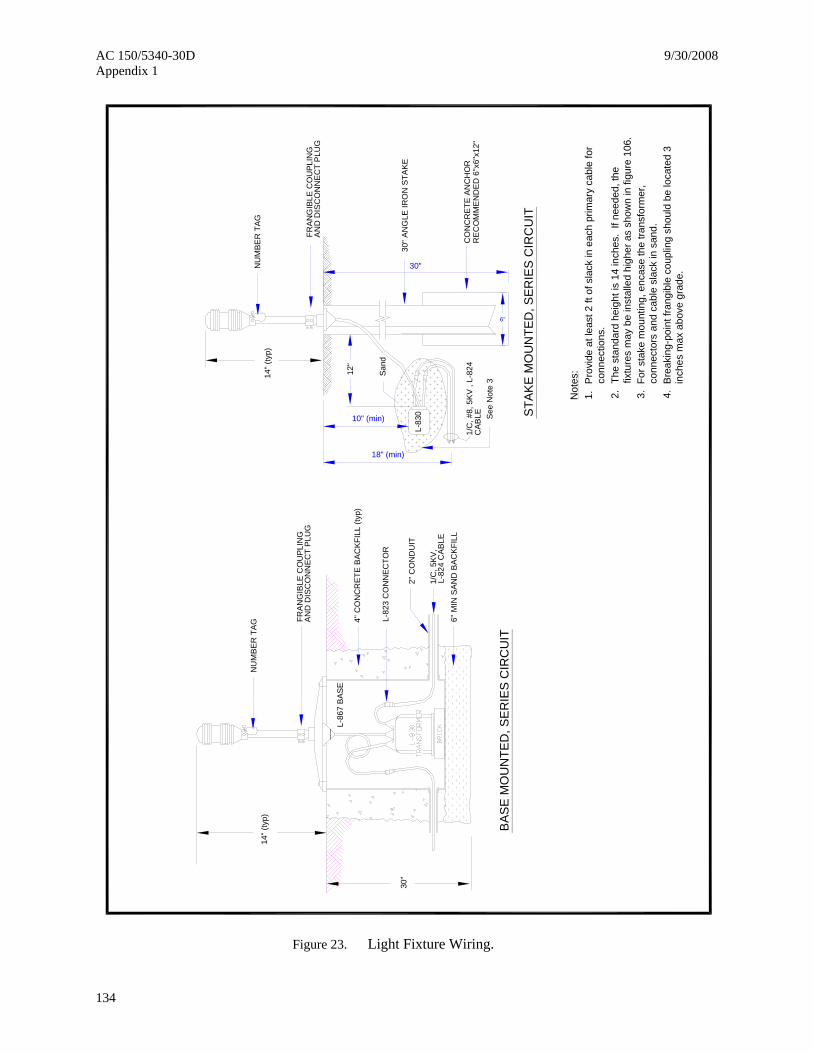
Not
es:
1. 2. 3.
Pro
vide
at l
east
2 ft
of s
lack
in e
ach
prim
ary
cabl
e fo
r co
nnec
tions
.
For s
take
mou
ntin
g, e
ncas
e th
e tra
nsfo
rmer
, co
nnec
tors
and
cab
le s
lack
in s
and.
The
stan
dard
hei
ght i
s 14
inch
es.
If ne
eded
, the
fix
ture
s m
ay b
e in
stal
led
high
er a
s sh
own
in fi
gure
106
.
2" C
ON
DU
IT
30"
San
d
6"
Bre
akin
g-po
int f
rang
ible
cou
plin
g sh
ould
be
loca
ted
3 in
ches
max
abo
ve g
rade
.4.
AN
D D
ISC
ON
NEC
T P
LUG
FRA
NG
IBLE
CO
UPL
ING
14" (
typ)
L-86
7 B
ASE
18" (min)
STA
KE
MO
UN
TED
, SER
IES
CIR
CU
IT
CA
BLE
1/C
, #8,
5K
V ,
L-82
4
30" A
NG
LE IR
ON
STA
KEL-
830 Se
e N
ote
3
30"
6" M
IN S
AN
D B
ACK
FILL
L-82
4 C
AB
LE
Figure 23. Light Fixture Wiring.
9/30/2008 AC 150/5340-30D Appendix 1
135
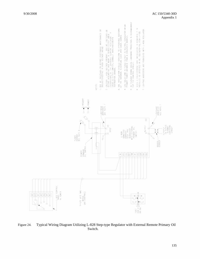
Figure 24. Typical Wiring Diagram Utilizing L-828 Step-type Regulator with External Remote Primary Oil Switch.
AC 150/5340-30D 9/30/2008 Appendix 1
136
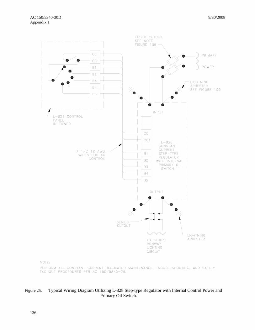
Figure 25. Typical Wiring Diagram Utilizing L-828 Step-type Regulator with Internal Control Power and Primary Oil Switch.
9/30/2008 AC 150/5340-30D Appendix 1
137
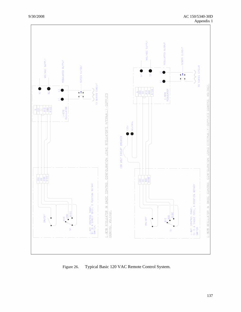
Figure 26. Typical Basic 120 VAC Remote Control System.

AC 150/5340-30D 9/30/2008 Appendix 1
138
Figure 27. Alternative 120 VAC Remote Control System.
9/30/2008 AC 150/5340-30D Appendix 1
139
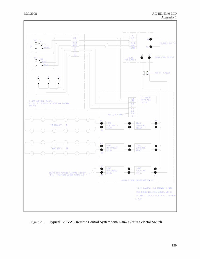
Figure 28. Typical 120 VAC Remote Control System with L-847 Circuit Selector Switch.
AC 150/5340-30D 9/30/2008 Appendix 1
140
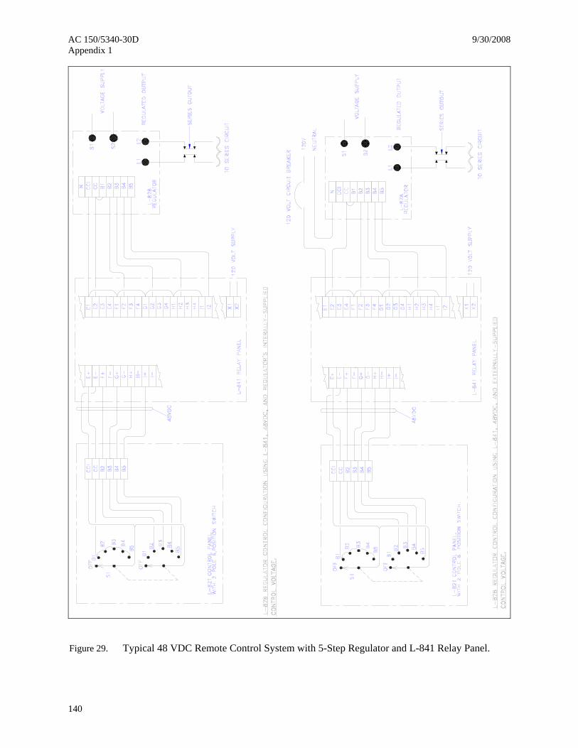
Figure 29. Typical 48 VDC Remote Control System with 5-Step Regulator and L-841 Relay Panel.

9/30/2008 AC 150/5340-30D Appendix 1
141
Figure 30. Typical 48 VDC Remote Control System with 3-Step Regulator and L-841 Relay Panel.
AC 150/5340-30D 9/30/2008 Appendix 1
142
02
2624
224
68
1012
1416
1820
X =
FEE
DER
CA
BLE
IN 1
000’
LEN
GTH
S
0.0
0.2
0.4
0.6
0.8
1.0
1.2
1.4
1.6
1.8
2.0
2.2
2.4
2.6
2.8
3.0
3.2
3.4
Y = LOAD IN KILOWATTS (KW)
00246810121416182022242628303234
Y = LOAD IN KILOWATTS (KW)X
= N
UM
BER
OF
LIG
HT
FIX
TUR
ES
1020
3040
5060
7080
9010
011
012
0
#8 W
IRE,
6.6
AM
PERE
PRIM
ARY
CU
RRE
NT
#6 W
IRE,
20.
0 A
MPE
RE
PRIM
ARY
CU
RRE
NT
#8 W
IRE,
20.
0 A
MPE
RE
PRIM
ARY
CU
RRE
NT
#8 W
IRE,
6.6
AM
PERE
PRIM
ARY
CU
RRE
NT
#6 W
IRE,
20.
0 A
MPE
RE
PRIM
ARY
CU
RRE
NT
#8 W
IRE,
20.
0 A
MPE
RE
PRIM
ARY
CU
RRE
NT
32
1
321
Y = 0.16112X
Y = 0.16112X
Y = 0.2562X
Y = 0.2562X
Y =
0.0
279
XY
= 0
.027
9 X
3 2 1
1 2 3
#8 W
IRE,
6.6
AM
PERE
PRIM
ARY
CU
RRE
NT
#6 W
IRE,
20.
0 A
MPE
REPR
IMA
RY C
UR
REN
T
#8 W
IRE,
20.
0 A
MPE
REPR
IMA
RY C
UR
REN
T
#8 W
IRE,
6.6
AM
PERE
PRIM
ARY
CU
RRE
NT
#6 W
IRE,
20.
0 A
MPE
REPR
IMA
RY C
UR
REN
T
#8 W
IRE,
20.
0 A
MPE
REPR
IMA
RY C
UR
REN
T
Y =
0.2
5 X
Y =
0.2
5 X
Y =
0.2
767
XY
= 0
.276
7 X
Y =
0.2
967
XY
= 0
.296
7 X
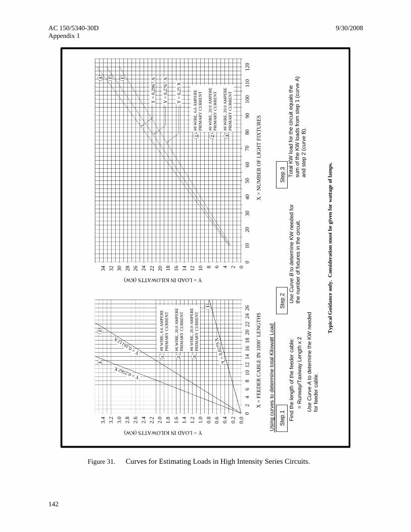
Usi
ng c
urve
s to
det
erm
ine
tota
l Kilo
wat
t Loa
d
Step
1
Find
the
leng
th o
f the
feed
er c
able
: =
Run
way
/Tax
iway
Len
gth
x 2
Use
Cur
ve A
to d
eter
min
e th
e KW
nee
ded
for f
eede
r cab
le.
Step
2
Use
Cur
ve B
to d
eter
min
e KW
nee
ded
for
the
num
ber o
f fix
ture
s in
the
circ
uit.
Step
3To
tal K
W lo
ad fo
r the
circ
uit e
qual
s th
e su
m o
f the
KW
load
s fro
m s
tep
1 (c
urve
A)
and
step
2 (c
urve
B).
Typ
ical
Gui
danc
e on
ly.
Con
sider
atio
n m
ust b
e gi
ven
for
wat
tage
of l
amps
.
Figure 31. Curves for Estimating Loads in High Intensity Series Circuits.

9/30/2008 AC 150/5340-30D Appendix 1
143
010
2030
4050
6070
8090
100
110
120
012345678
00.
0
0.1
0.2
0.3
0.4
0.5
12
34
56
78
910
1112
45 W
ATT U
NITS
45 W
ATT U
NITS
30 W
ATT
UNIT
S
30 W
ATT
UNIT
S
No.
8 A
WG
CA
BLE
(6.6
A)
No.
8 A
WG
CA
BLE
(6.6
A)
Y = LOAD IN KILOWATTS (KW) Y = LOAD IN KILOWATTS (KW)
X =
FEE
DER
CA
BLE
IN 1
,000
’ LEN
GTH
S
X =
NU
MB
ER O
F LI
GH
T FI
XTU
RES
Usi
ng c
urve
s to
det
erm
ine
tota
l Kilo
wat
t Loa
d
Com
puta
tions
bas
ed o
n ac
tual
circ
uit l
oad
test
s.1.
In C
urve
A fin
d ki
low
att l
oad
(KW
) for
the
tota
l num
ber o
f fix
ture
s,us
ing
the
appl
icab
le li
nes
(i.e.
45
wat
t or 3
0 w
att).
2.
Basi
s fo
r com
putin
g un
it lo
ads
in C
urve
A:
3.
30/4
5 w
att t
rans
form
er w
ith 4
5 w
att l
amp
Cab
le lo
ss, l
amp
tole
ranc
e, e
tc.
30/4
5 w
att t
rans
form
er w
ith 3
0 w
att l
amp
Cab
le lo
ss, l
amp
tole
ranc
e, e
tc.
Tota
l est
imat
ed lo
ad p
er 4
5 w
att u
nit
Tota
l est
imat
ed lo
ad p
er 3
0 w
att u
nit
54.7
wat
ts10
.3 w
atts
40.4
wat
ts9.
6 w
atts
65.0
wat
ts
50.0
wat
ts
Basi
s fo
r com
putin
g lo
ad p
er 1
000
ft of
No.
8 A
WG
cab
le
in C
urve
B:
I2 R =
(6.6
A)2 x
0.64
05 o
hms/
1,00
0 ft
= 27
.9 w
atts
/100
0 ft
4.
Tota
l KW
load
per
circ
uit e
qual
the
sum
of t
he K
W lo
ads
from
cur
ve A
and
cur
ve B
. 5.
Figure 32. Curves for Estimating Loads in Medium Intensity Series Circuits.
AC 150/5340-30D 9/30/2008 Appendix 1
144
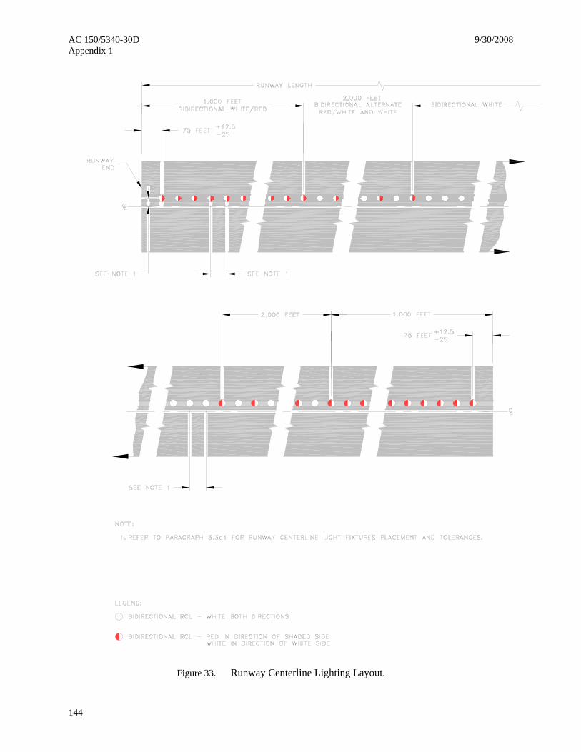
Figure 33. Runway Centerline Lighting Layout.
9/30/2008 AC 150/5340-30D Appendix 1
145
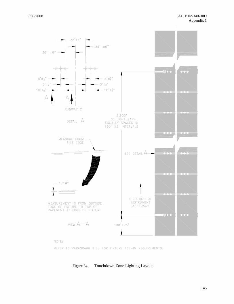
Figure 34. Touchdown Zone Lighting Layout.
AC 150/5340-30D 9/30/2008 Appendix 1
146
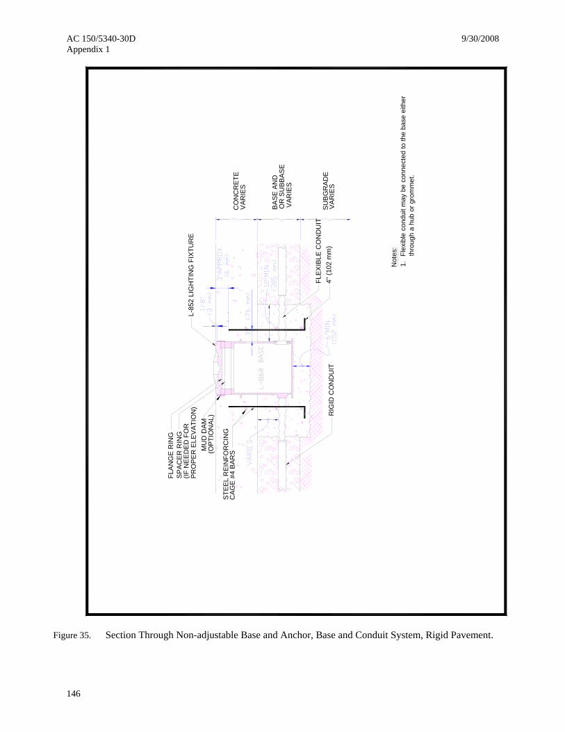
Flex
ible
con
duit
may
be
conn
ecte
d to
the
base
eith
er
thro
ugh
a hu
b or
gro
mm
et.
Not
es:
1.
RIG
ID C
ON
DU
IT
(OPT
ION
AL)
PRO
PER
ELE
VAT
ION
)(IF
NE
EDE
D F
OR
MU
D D
AM
4" (1
02 m
m)
FLA
NG
E R
ING
FLEX
IBLE
CO
ND
UIT
SPAC
ER R
ING
L-85
2 LI
GH
TIN
G F
IXTU
RE
SUB
GR
ADE
VAR
IES
VAR
IES
BASE
AN
DO
R S
UBB
ASE
VAR
IES
CO
NC
RET
EC
AGE
#4 B
ARS
STEE
L R
EIN
FOR
CIN
G
Figure 35. Section Through Non-adjustable Base and Anchor, Base and Conduit System, Rigid Pavement.

9/30/2008 AC 150/5340-30D Appendix 1
147
6"(1
52 m
m) M
in.
12"M
IN.
Flex
ible
Con
duit
L-86
8 B
ase
Top
Sec
tion
L-85
0, L
ight
Fix
ture
SU
BG
RA
DE
VAR
IES
VA
RIE
S
BA
SE
AN
D/O
RS
UB
BA
SE
VA
RIE
SAS
PH
ALT
Bot
tom
Sec
tion
Item
P-6
05 T
ype
IIIC
ompa
tible
with
Asp
halt
Not
es:
1.Fl
exib
le c
ondu
it m
ay b
e co
nnec
ted
to th
e ba
se e
ither
th
roug
h a
hub
or g
rom
met
.
(3 m
m)
(Opt
iona
l)
Item
P-6
06 C
ompa
tible
with
Asp
halt
Rig
idC
ondu
it
(If n
eede
d)S
pace
r Rin
g
Mud
Dam
Flan
ge R
ing
L-86
8 B
ase
Con
cret
e A
ncho
r
1/8"
Figure 36. Section Through Non-adjustable Base and Anchor, Base and Conduit System, Flexible Pavement.

AC 150/5340-30D 9/30/2008 Appendix 1
148
Figure 37. Runway Centerline Light – Shallow Base & Conduit Installation.