appendix 11: new features in v 3.9 a - performance …performancetrends.com/pdfs/engine analyzer pro...
TRANSCRIPT
Appendix 11: New Features in v 3.9 A
Engine Analyzer Pro has had many updates since this user manual was written for the original v2.1 for Windows. These include v2.1 B, v2.1C, v2.1D, v3.3, v3.5 and now v3.9. Here is a brief listing of some of the features new since v3.5 was released, including Version 3.9:
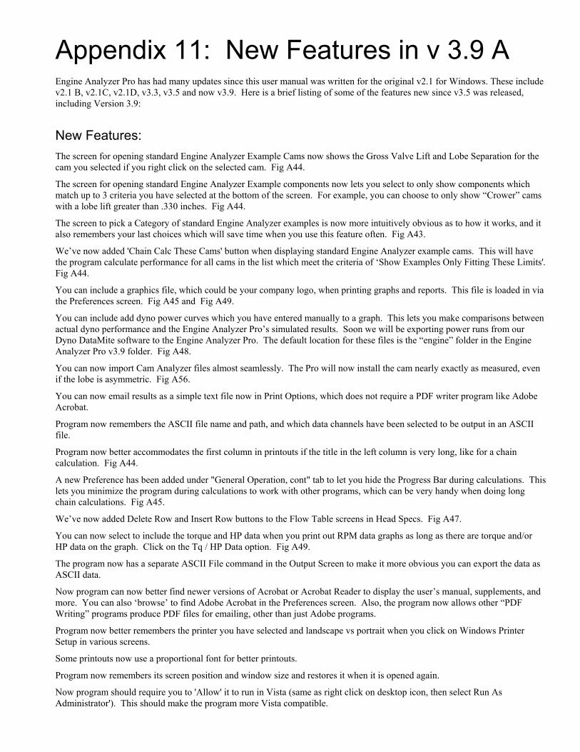
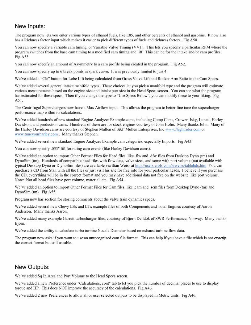
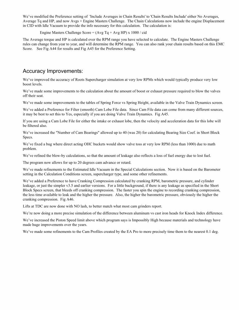
New Features: The screen for opening standard Engine Analyzer Example Cams now shows the Gross Valve Lift and Lobe Separation for the cam you selected if you right click on the selected cam. Fig A44.
The screen for opening standard Engine Analyzer Example components now lets you select to only show components which match up to 3 criteria you have selected at the bottom of the screen. For example, you can choose to only show “Crower” cams with a lobe lift greater than .330 inches. Fig A44.
The screen to pick a Category of standard Engine Analyzer examples is now more intuitively obvious as to how it works, and it also remembers your last choices which will save time when you use this feature often. Fig A43.
We’ve now added 'Chain Calc These Cams' button when displaying standard Engine Analyzer example cams. This will have the program calculate performance for all cams in the list which meet the criteria of ‘Show Examples Only Fitting These Limits'. Fig A44.
You can include a graphics file, which could be your company logo, when printing graphs and reports. This file is loaded in via the Preferences screen. Fig A45 and Fig A49.
You can include add dyno power curves which you have entered manually to a graph. This lets you make comparisons between actual dyno performance and the Engine Analyzer Pro’s simulated results. Soon we will be exporting power runs from our Dyno DataMite software to the Engine Analyzer Pro. The default location for these files is the “engine” folder in the Engine Analyzer Pro v3.9 folder. Fig A48.
You can now import Cam Analyzer files almost seamlessly. The Pro will now install the cam nearly exactly as measured, even if the lobe is asymmetric. Fig A56.
You can now email results as a simple text file now in Print Options, which does not require a PDF writer program like Adobe Acrobat.
Program now remembers the ASCII file name and path, and which data channels have been selected to be output in an ASCII file.
Program now better accommodates the first column in printouts if the title in the left column is very long, like for a chain calculation. Fig A44.
A new Preference has been added under "General Operation, cont" tab to let you hide the Progress Bar during calculations. This lets you minimize the program during calculations to work with other programs, which can be very handy when doing long chain calculations. Fig A45.
We’ve now added Delete Row and Insert Row buttons to the Flow Table screens in Head Specs. Fig A47.
You can now select to include the torque and HP data when you print out RPM data graphs as long as there are torque and/or HP data on the graph. Click on the Tq / HP Data option. Fig A49.
The program now has a separate ASCII File command in the Output Screen to make it more obvious you can export the data as ASCII data.
Now program can now better find newer versions of Acrobat or Acrobat Reader to display the user’s manual, supplements, and more. You can also ‘browse’ to find Adobe Acrobat in the Preferences screen. Also, the program now allows other “PDF Writing” programs produce PDF files for emailing, other than just Adobe programs.
Program now better remembers the printer you have selected and landscape vs portrait when you click on Windows Printer Setup in various screens.
Some printouts now use a proportional font for better printouts.
Program now remembers its screen position and window size and restores it when it is opened again.
Now program should require you to 'Allow' it to run in Vista (same as right click on desktop icon, then select Run As Administrator'). This should make the program more Vista compatible.
New Inputs: The program now lets you enter various types of ethanol fuels, like E85, and other percents of ethanol and gasoline. It now also has a Richness factor input which makes it easier to pick different types of fuels and richness factors. Fig A50.
You can now specify a variable cam timing, or Variable Valve Timing (VVT). This lets you specify a particular RPM where the program switches from the base cam timing to a modified cam timing and lift. This can be for the intake and/or cam profiles. Fig A53.
You can now specify an amount of Asymmetry to a cam profile being created in the program. Fig A52.
You can now specify up to 6 break points in spark curve. It was previously limited to just 4.
We’ve added a “Clc” button for Lobe Lift being calculated from Gross Valve Lift and Rocker Arm Ratio in the Cam Specs.
We’ve added several general intake manifold types. These choices let you pick a manifold type and the program will estimate various measurements based on the engine size and intake port size in the Head Specs screen. You can see what the program has estimated for these specs. Then if you change the type to “Use Specs Below”, you can modify these to your liking. Fig A51.
The Centrifugal Superchargers now have a Max Airflow input. This allows the program to better fine tune the supercharger performance map within its calculations.
We’ve added hundreds of new standard Engine Analyzer Example cams, including Comp Cams, Crower, Isky, Lunati, Harley Davidson, and production cams. Hundreds of these are for stock engines courtesy of John Holm. Many thanks John. Many of the Harley Davidson cams are courtesy of Stephen Mullen of S&P Mullen Enterprises, Inc www.Nightrider.com or www.tuneyourharley.com . Many thanks Stephen.
We’ve added several new standard Engine Analyzer Example cam categories, especially Imports. Fig A43.
You can now specify .053" lift for rating cam events (like Harley Davidson cams).
We’ve added an option to import Other Format Files for Head files, like .flw and .dfw files from Desktop Dyno (tm) and DynoSim (tm). Hundreds of compatible head files with flow data, valve sizes, and some with port volume (not available with typical Desktop Dyno or D ynoSim files) are available via Stan Weiss at http://users.erols.com/srweiss/tablehdc.htm You can purchase a CD from Stan with all the files or just visit his site for free info for your particular heads. I believe if you purchase the CD, everything will be in the correct format and you may have additional data not free on the website, like port volume. Note: Not all head files have port volume, material, etc. Fig A54.
We’ve added an option to import Other Format Files for Cam files, like .cam and .scm files from Desktop Dyno (tm) and DynoSim (tm). Fig A55.
Program now has section for storing comments about the valve train dynamics specs.
We’ve added several new Chevy LSx and LTx example files of both Components and Total Engines courtesy of Aaron Anderson. Many thanks Aaron.
We’ve added many example Garrett turbocharger files, courtesy of Bjørn Deildok of SWR Performance, Norway. Many thanks Bjorn.
We’ve added the ability to calculate turbo turbine Nozzle Diameter based on exhaust turbine flow data.
The program now asks if you want to use an unrecognized cam file format. This can help if you have a file which is not exactly the correct format but still useable.
New Outputs: We’ve added Sq In Area and Port Volume to the Head Specs screen.
We’ve added a new Preference under "Calculations, cont" tab to let you pick the number of decimal places to use to display torque and HP. This does NOT improve the accuracy of the calculations. Fig A46.
We’ve added 2 new Preferences to allow all or user selected outputs to be displayed in Metric units. Fig A46.
We’ve modified the Preference setting of 'Include Averages in Chain Results' to 'Chain Results Include' either No Averages, Average Tq and HP, and now Avgs + Engine Masters Challenge. The Chain Calculations now include the engine Displacement in CID with Idle Vacuum to provide the info necessary for this calculation. The calculation is:
Engine Masters Challenge Score = (Avg Tq + Avg HP) x 1000 / cid
The Average torque and HP is calculated over the RPM range you have selected to calculate. The Engine Masters Challenge rules can change from year to year, and will determine the RPM range. You can also rank your chain results based on this EMC Score. See Fig A44 for results and Fig A45 for the Preference Setting.
Accuracy Improvements: We’ve improved the accuracy of Roots Supercharger simulation at very low RPMs which would typically produce very low boost levels.
We’ve made some improvements to the calculation about the amount of boost or exhaust pressure required to blow the valves off their seat.
We’ve made some improvements to the tables of Spring Force vs Spring Height, available in the Valve Train Dynamics screen.
We’ve added a Preference for Filter (smooth) Cam Lobe File data. Since Cam File data can come from many different sources, it may be best to set this to Yes, especially if you are doing Valve Train Dynamics. Fig A45.
If you are using a Cam Lobe File for either the intake or exhaust lobe, then the velocity and acceleration data for this lobe will be filtered also.
We’ve increased the "Number of Cam Bearings" allowed up to 40 (was 20) for calculating Bearing Size Coef. in Short Block Specs.
We’ve fixed a bug where direct acting OHC buckets would show valve toss at very low RPM (less than 1000) due to math problem.
We’ve refined the blow-by calculations, so that the amount of leakage also reflects a loss of fuel energy due to lost fuel.
The program now allows for up to 20 degrees cam advance or retard.
We’ve made refinements to the Estimated Idle Vacuum in the Special Calculations section. Now it is based on the Barometer setting in the Calculation Conditions screen, supercharger type, and some other refinements.
We’ve added a Preference to have Cranking Compression calculated by cranking RPM, barometric pressure, and cylinder leakage, or just the simpler v3.5 and earlier versions. For a little background, if there is any leakage as specified in the Short Block Specs screen, that bleeds off cranking compression. The faster you spin the engine to recording cranking compression, the less time available to leak and the higher the pressure. Also, the higher the barometric pressure, obviously the higher the cranking compression. Fig A46.
Lifts at TDC are now done with NO lash, to better match what most cam grinders report.
We’re now doing a more precise simulation of the difference between aluminum vs cast iron heads for Knock Index difference.
We’ve increased the Piston Speed limit above which program says is Impossibly High because materials and technology have made huge improvements over the years.
We’ve made some refinements to the Cam Profiles created by the EA Pro to more precisely time them to the nearest 0.1 deg.

Figure A43 New Features for Using Standard Engine Example Component Files
Click on Retrieve from Library and you are presented with choices. This list of options can grow as you choose different options at the next ‘Retrieve’ screen show below. For example, the ‘Corvair…’ choice is presented because you have picked a ‘Corvair…’ cam in the past.
Click on ‘Std Engine Analyzer Cam Examples’ button to open up the screen below, showing categories of literally thousands of cam specs preloaded from which you can choose.
Just to contrast the ‘Std Engine Analyzer Example’ files from ‘Engine Analyzer Pro’ files, the Pro files are listed in this section, and when you click on them, a preview is shown to the right. Most all the commands and options above the ‘Std Engine..’ button relate to Pro files which typically contain more detail than the ‘Std Engine Analyzer…’ examples.
Pick a Category of Std Engine Analyzer Example file, then click the Use Category button.
Now there’s a Use Category and Cancel button in this section for Examples Added by User. They act the same as the original Use Category and Cancel button in the Performance Trends’ Examples section to the left. Note: You typically add Examples if you have our Standard Engine Analyzer program and have linked the Pro and Std programs in EA Pro’s Preferences. When you save a Cam /Valve Train file in the Pro, you are saving it in EA Pro format. Note: You can also add a Category and “Other Format” cam files as shown in Figure A55

Figure A44 New Features for Using Standard Engine Example Component Files, cont
If you right click on a cam you have picked (which will be highlighted in blue as shown here), several calculated parameters for that cam are shown.
In this section, you can choose to Show… ‘All Examples’ or ‘Only These’ as shown. Then you can use the 3 groups of conditions to determine what examples are shown. For example, in this screen, we have picked to only show cams with the phrase ‘Hyd’ in the Lifter Profile description and an Int Lobe Lift greater than .29 inches.
Click on this button (only available for example Cams) and the program will do a chain calculation on all cams listed
Results for the Cam Examples you choose to keep in the screen above. Note that these are ranked by ‘Average Tq’ by any of the 5 choices in the ‘Rank Results’ combo list. The ‘Eng Masters Challenge Score’ is only possible if you’ve turned it on in Preferences.
All these torque and HP results (and Engine Masters Challenge Score) are shown to 2 decimal places because that Preference has been turned. If that Preference was not turned on, these numbers would have been shown to the nearest whole number, that 366.20 would be shown as
A Preference lets you choose to show the Average Torque and HP, and also include the Engine Masters Challenge column in the Chain Calculation results.
The program now better expands this first column to fit all the descriptive data given.
Engine Masters Challenge is now a choice for Ranking if you set the appropriate Preference.
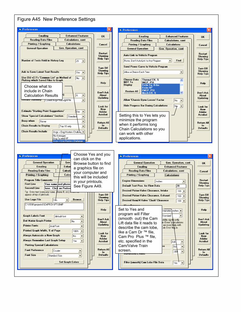
Figure A45 New Preference Settings
Choose what to include in Chain Calculation Results
Setting this to Yes lets you minimize the program when it performs long Chain Calculations so you can work with other applications.
Choose Yes and you can click on the Browse button to find a graphics file on your computer and this will be included in your printouts. See Figure A49.
Set to Yes and program will Filter (smooth out) the Cam Lift data file it reads to describe the cam lobe, like a Cam Dr ™ file, Cam Pro Plus ™ file, etc. specified in the Cam/Valve Train screen.
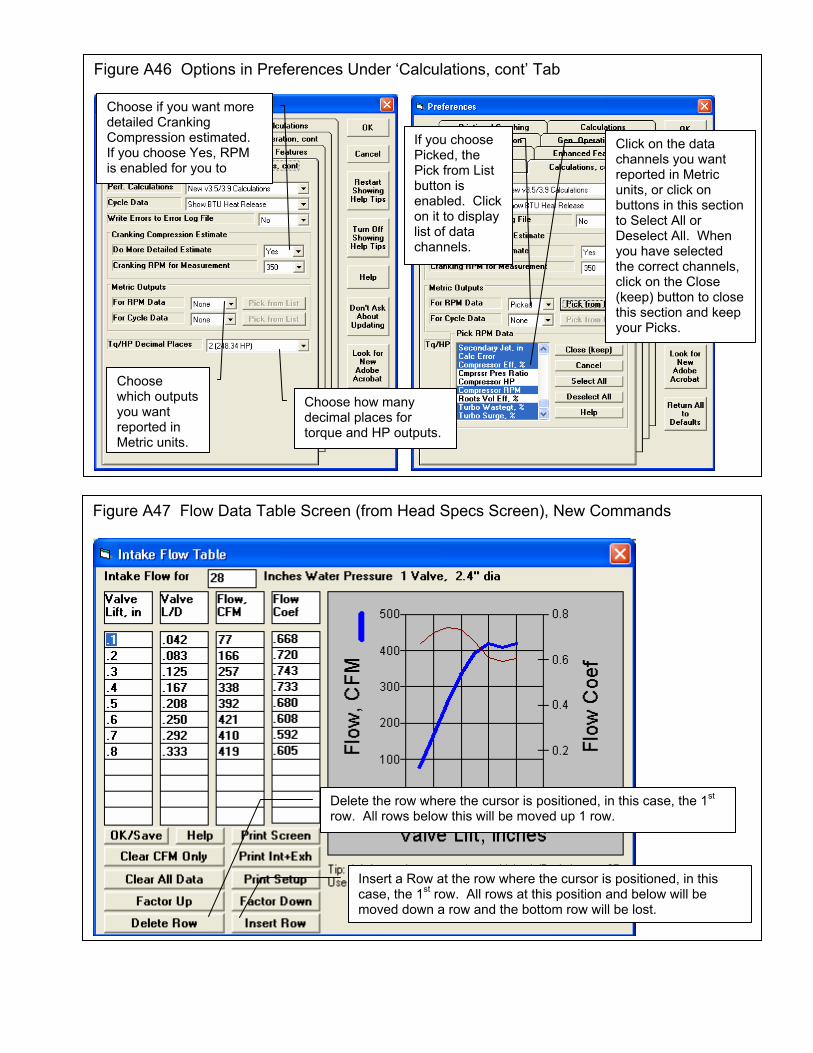
Figure A46 Options in Preferences Under ‘Calculations, cont’ Tab
Choose which outputs you want reported in Metric units.
Choose how many decimal places for torque and HP outputs.
If you choose Picked, the Pick from List button is enabled. Click on it to display list of data channels.
Click on the data channels you want reported in Metric units, or click on buttons in this section to Select All or Deselect All. When you have selected the correct channels, click on the Close (keep) button to close this section and keep your Picks.
Choose if you want more detailed Cranking Compression estimated. If you choose Yes, RPM is enabled for you to
Figure A47 Flow Data Table Screen (from Head Specs Screen), New Commands
Delete the row where the cursor is positioned, in this case, the 1st row. All rows below this will be moved up 1 row.
Insert a Row at the row where the cursor is positioned, in this case, the 1st row. All rows at this position and below will be moved down a row and the bottom row will be lost.

Figure A48 Including Actual Dyno Curves with Graphs
In Graph screen, click on File, the Actual Dyno Curves, then Enter/Edit Dyno Curve Data to get screen shown to right.
Click on File for these options to Open or Save this data set.
Click here to calculate an approximate power curve. You can then edit those data points.
Type in your RPM, torque and/or HP data points. Once you have entered 2, the 3rd input is calculated and filled in for you.
Click here to include this data on the graph with Engine Analyzer Pro calculated data, as shown below.
Engine Analyzer Pro’s calculated power curves.
Power curves from ‘Actual Dyno Curves’ screen shown above.

Figure A49 Including a Torque and HP Data Table with the Printed Graph
Click on Format, then Edit Printed Comments to get screen shown to right.
Check Tq/HP Data to include torque and HP data table at the bottom of the printed graph. Note: This data is ONLY printed if the graph includes torque and HP data vs RPM.
Printed Logo graphics file will appear here, as picked in Preferences screen shown in Figure A45
Data Tables appear here, under the graph on printouts.
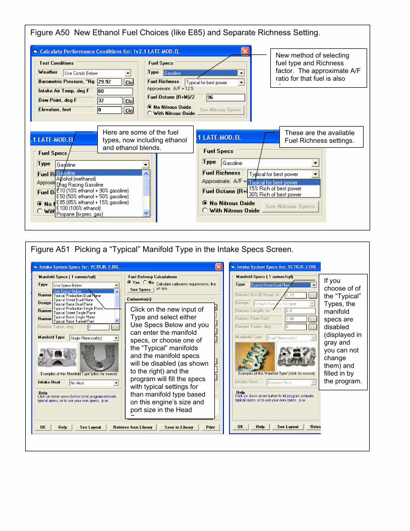
Figure A50 New Ethanol Fuel Choices (like E85) and Separate Richness Setting.
New method of selecting fuel type and Richness factor. The approximate A/F ratio for that fuel is also h
Here are some of the fuel types, now including ethanol and ethanol blends.
These are the available Fuel Richness settings.
Figure A51 Picking a “Typical” Manifold Type in the Intake Specs Screen.
Click on the new input of Type and select either Use Specs Below and you can enter the manifold specs, or choose one of the “Typical” manifolds and the manifold specs will be disabled (as shown to the right) and the program will fill the specs with typical settings for than manifold type based on this engine’s size and port size in the Head S
If you choose of of the “Typical” Types, the manifold specs are disabled (displayed in gray and you can not change them) and filled in by the program.
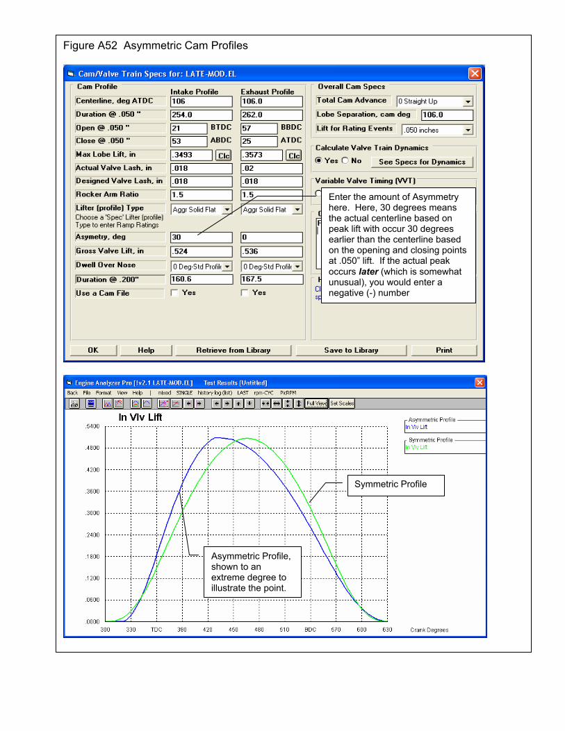
Figure A52 Asymmetric Cam Profiles
Enter the amount of Asymmetry here. Here, 30 degrees means the actual centerline based on peak lift with occur 30 degrees earlier than the centerline based on the opening and closing points at .050” lift. If the actual peak occurs later (which is somewhat unusual), you would enter a negative (-) number
Symmetric Profile
Asymmetric Profile, shown to an extreme degree to illustrate the point.
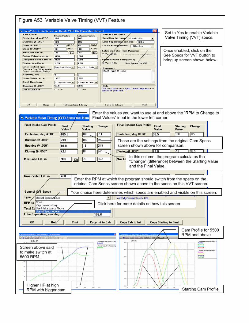
Figure A53 Variable Valve Timing (VVT) Feature
Set to Yes to enable Variable Valve Timing (VVT) specs.
Once enabled, click on the See Specs for VVT button to bring up screen shown below.
Your choice here determines which specs are enabled and visible on this screen.
Enter the RPM at which the program should switch from the specs on the original Cam Specs screen shown above to the specs on this VVT screen.
Enter the values you want to use at and above the “RPM to Change to Final Values” input in the lower left corner.
These are the settings from the original Cam Specs screen shown above for comparison.
In this column, the program calculates the “Change” (difference) between the Starting Value and the Final Value.
Screen above said to make switch at 5500 RPM.
Higher HP at high RPM with bigger cam. Starting Cam Profile
Click here for more details on how this screen
Cam Profile for 5500 RPM and above
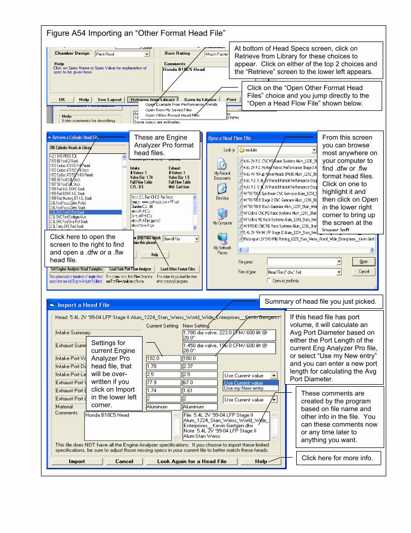
Figure A54 Importing an “Other Format Head File”
At bottom of Head Specs screen, click on Retrieve from Library for these choices to appear. Click on either of the top 2 choices and the “Retrieve” screen to the lower left appears.
Click on the “Open Other Format Head Files” choice and you jump directly to the “Open a Head Flow File” shown below.
Click here to open the screen to the right to find and open a .dfw or a .flw head file.
These are Engine Analyzer Pro format head files.
From this screen you can browse most anywhere on your computer to find .dfw or .flw format head files. Click on one to highlight it and then click on Open in the lower right corner to bring up the screen at the lower left
Settings for current Engine Analyzer Pro head file, that will be over-written if you click on Import in the lower left corner.
Summary of head file you just picked.
If this head file has port volume, it will calculate an Avg Port Diameter based on either the Port Length of the current Eng Analyzer Pro file, or select “Use my New entry” and you can enter a new port length for calculating the Avg Port Diameter.
These comments are created by the program based on file name and other info in the file. You can these comments now or any time later to anything you want.
Click here for more info.
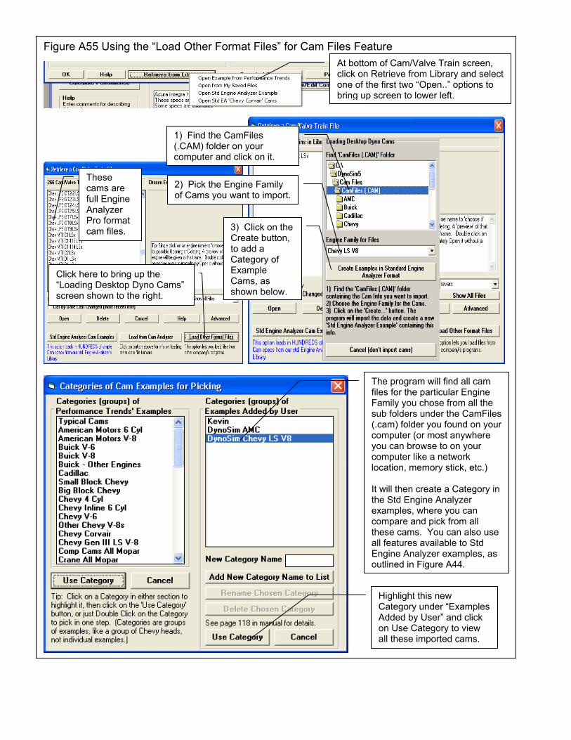
Figure A55 Using the “Load Other Format Files” for Cam Files Feature
At bottom of Cam/Valve Train screen, click on Retrieve from Library and select one of the first two “Open..” options to bring up screen to lower left.
Click here to bring up the “Loading Desktop Dyno Cams” screen shown to the right.
These cams are full Engine Analyzer Pro format cam files.
1) Find the CamFiles (.CAM) folder on your computer and click on it.
2) Pick the Engine Family of Cams you want to import.
3) Click on the Create button, to add a Category of Example Cams, as shown below.
The program will find all cam files for the particular Engine Family you chose from all the sub folders under the CamFiles (.cam) folder you found on your computer (or most anywhere you can browse to on your computer like a network location, memory stick, etc.) It will then create a Category in the Std Engine Analyzer examples, where you can compare and pick from all these cams. You can also use all features available to Std Engine Analyzer examples, as outlined in Figure A44.
Highlight this new Category under “Examples Added by User” and click on Use Category to view all these imported cams.
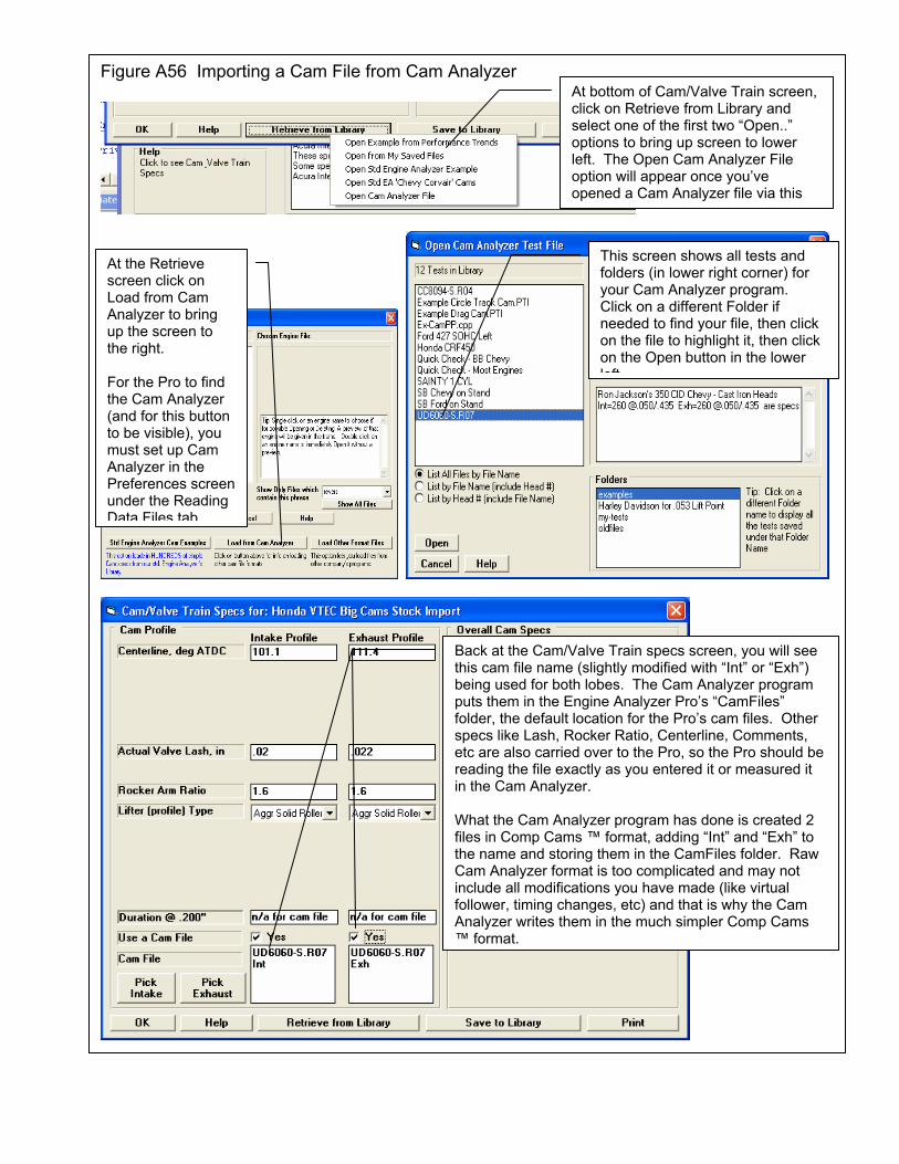
Figure A56 Importing a Cam File from Cam Analyzer
At bottom of Cam/Valve Train screen, click on Retrieve from Library and select one of the first two “Open..” options to bring up screen to lower left. The Open Cam Analyzer File option will appear once you’ve opened a Cam Analyzer file via this
At the Retrieve screen click on Load from Cam Analyzer to bring up the screen to the right. For the Pro to find the Cam Analyzer (and for this button to be visible), you must set up Cam Analyzer in the Preferences screen under the Reading Data Files tab
This screen shows all tests and folders (in lower right corner) for your Cam Analyzer program. Click on a different Folder if needed to find your file, then click on the file to highlight it, then click on the Open button in the lower left
Back at the Cam/Valve Train specs screen, you will see this cam file name (slightly modified with “Int” or “Exh”) being used for both lobes. The Cam Analyzer program puts them in the Engine Analyzer Pro’s “CamFiles” folder, the default location for the Pro’s cam files. Other specs like Lash, Rocker Ratio, Centerline, Comments, etc are also carried over to the Pro, so the Pro should be reading the file exactly as you entered it or measured it in the Cam Analyzer. What the Cam Analyzer program has done is created 2 files in Comp Cams ™ format, adding “Int” and “Exh” to the name and storing them in the CamFiles folder. Raw Cam Analyzer format is too complicated and may not include all modifications you have made (like virtual follower, timing changes, etc) and that is why the Cam Analyzer writes them in the much simpler Comp Cams ™ format.

Appendix 12: New Features in v 3.9 B
Engine Analyzer Pro v3.9 B has many updates, new example engine files and component files, and improved features. Here is a listing of the features new since v3.9 A was released.
New Features: You can now link your engine file to a picture file. This picture appears on main screen and adjusts to fit the available screen. This picture file can also be included in printouts of graphs and reports. Fig A57-A58.
You can now do Chain Calculations on Opening and Closing Cam Events.
Program now has a Graph on the Cam Specs screen to give you an idea of the shape of the valve lift curves, this graph is updated with each change you make to the inputs. You can also click the graph lines in the Cam/Valve Train specs screen and the data at that point are displayed at the bottom of the graph. Fig A59.
The program has several new features for outputting reports as ASCII text files. Fig A60. These files are useful for using results in other programs like Microsoft Excel ™. These features include:
• Option for exporting as simple text (.txt) or files more compatible with Excel, like comma separated (.csv).
• There is a new Browse button for creating names locating where the files are written.
• There’s a new option for outputting the data as either Rows or Columns.
• There’s a new field where you can enter several comments which will appear at the bottom of the ASCII file.
When opening a Total Engine File, there is a new "Compare" button. If you click on a file name (but not open it), you can click this button and see what modifications have been done to a particular file compared to the file you are currently working with. Fig A61.
Printed graphs have a new layout which eliminates the left side border which could appear “broken” on some printers.
When sending files to vehicle programs, there is a new Browse button for looking for files and programs.
The program now sends files you delete to the Recycle Bin instead of permanently deleting them. This allows you to recover them from the Recycle bin if you made a mistake.
The program now works better if you are pressing the < > and >< buttons on graph to change scales or after changing scales you go to print the graph.
There is a new option on the Graph screen under File called “Email Graph Printout as PDF” file.
The program now has many enhancements for Email Preferences for more modern email servers. Fig A62-A63.
The program has a new “Convert” option to be able to modify the CFM entries on the screen for entering detailed turbo map data. This allows the user to enter data in various units, and then convert the flow data to CFM or increase or reduce the data by a particular factor. Enterprise Edition only.
The input grid on the screen for detailed turbo or centrifugal map screen will now enlarge better if the screen is enlarged. This makes it much easier to read the grid. Also, now clicking on the Turbo or Cent SC Map will highlight the cell at the point you clicked on the map. Enterprise Edition only.
You can now load a .jpg image of a compressor map for more efficient and accurate “translating” its data into an Engine Analyzer Pro compressor map file. Enterprise Edition only.
New Inputs: The Enterprise Edition has a completely new input screen called Valve Spring Dynamics. Here you can describe 1, 2 or 3 valve springs for Intake and Exhaust and the program will evaluate how they will work with a particular valve train. New graph options let you watch how well controlled the coils behave, and if you are likely to have valve spring surge. With valve spring dynamics On, the program will also simulate valve bounce on the seat and how that valve bounce re-opens a valve and could affect power. Note: For this first version, the units in this screen are always in English units. Files you create in Engine Analyzer Pro are saved in the Users Spring Files folder.

The program now has 2 more types of Roots Supercharger Types to pick from, “Modern” and “Modern 2000+”. The original Roots Supercharger type (now called “Standard”) is for an old style GMC blower, like a “671”. The new types represent superchargers installed on production supercharged cars like modern Mustangs and Corvettes. Fig A64.
The program now allows for a “ramp” (gradual) change in valve duration, timing and lift when simulating VVT (variable valve timing). Fig A68.
The program will now read a “.p” file format of cam file.
Valve Spring “Compression to Bind” is a new input in the Valve Train Dynamics screen and the Valve Spring Dynamics screen. The program also considers this bind travel when doing valve train dynamics calculations for improved valve train simulation accuracy. There is also a new “Clc” calculation utility screen for calculating this travel. Fig A65.
There are now more Std Engine Analyzer example cams supplied with 'the Pro were available, mostly Comp Cams BB and SB Chevy.
In Head Specs, there is a new choice for Chamber Designs which are for modern Direct Injection. Fig A66.
Program now lets you select which ports to use for importing tests from the Port Flow Analyzer program. Fig A67.
We’ve added several new Example Total Engine Files, component files like Complete Heads, and full compressor maps for both turbos and centrifugal superchargers.
You can now use KG for force for calculating spring force and rate for valve train dynamics in 'Clc' screen.
There’s a new Preference called "Valve Lift at TDC Assumes 0 Lash" under the Calculations tab. The Valve Lift @ TDC is shown in the Special Calculations section of the results. If you choose Yes for this, the program assumes there is NO LASH when checking this lift, like if checking with a light duty test spring. If you choose No, the program assumes there is the lash the program used for performance calculations. For Hydraulic lifters, this is typically assumed to be .006" lash, or compliance.
New Outputs: When doing Valve Spring Dynamics, the program has new Graph Options for graphing the valve spring motion, and an “animation” screen to visualize the valve spring motion. Enterprise Edition only.
If you choose a Cam File for the cam profile in the Cam/Valve Train specs screen, the program now checks the Max Valve Lift for the cam file, and displays it on the screen.
There is a new Preference to allow you to pick of number of decimal places for RPM data to be reported.
Printouts now show proper units for Engine Input Specs in either Inches or MM, depending on your choice of units in Preferences.
Bind Clearance now displayed in the Special Calculations section of the Report Screen after calculating performance. Bind Clearances is calculated from peak valve lift from the cam specs and the new input Valve Spring “Compression to Bind”.
The Special Calculations section at the bottom of results now are shown in mm instead of inches where appropriate.
Accuracy: The program considers the new input of Valve Spring “Compression to Bind” when doing valve train dynamics calculations for improved valve train simulation accuracy.
The new Roots Supercharger types will greatly improve accuracy of simulating modern positive displacement (roots type) superchargers. See New Inputs section.
The program has refined its simulation of plenum volume for race EFI and tunnel ram intake manifolds.
There has been some refining of the Knock Index calculation. This does not affect performance calculations.

Figure A57 Picture File Features
Click here for Picture File options
Picture File shown here
If screen is enlarged, the picture file will fill the available screen area.
File options in Graph screen.
Options for including picture file in graph printouts.

Figure A58 Picture File Features, cont
Printing picture nomal
Printing picture smaller
Printing picture file in reports
Printing picture file smaller in Reports
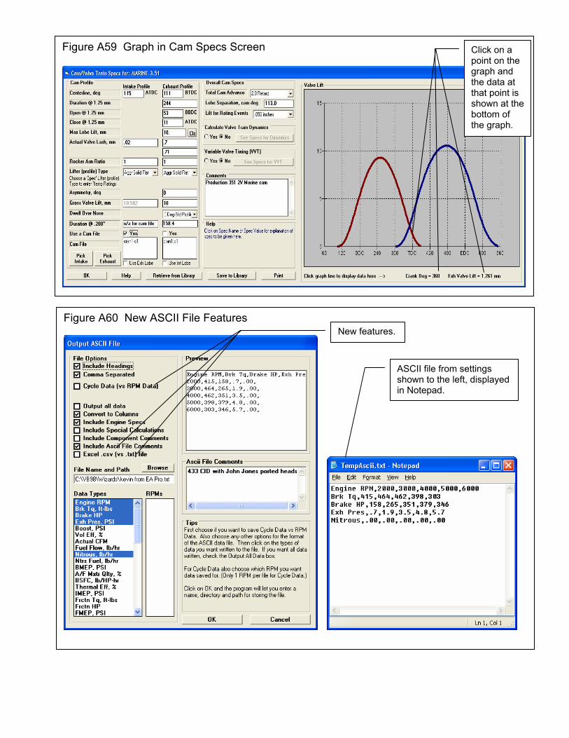
Figure A60 New ASCII File Features
New features.
ASCII file from settings shown to the left, displayed in Notepad.
Figure A59 Graph in Cam Specs Screen
Click on a point on the graph and the data at that point is shown at the bottom of the graph.
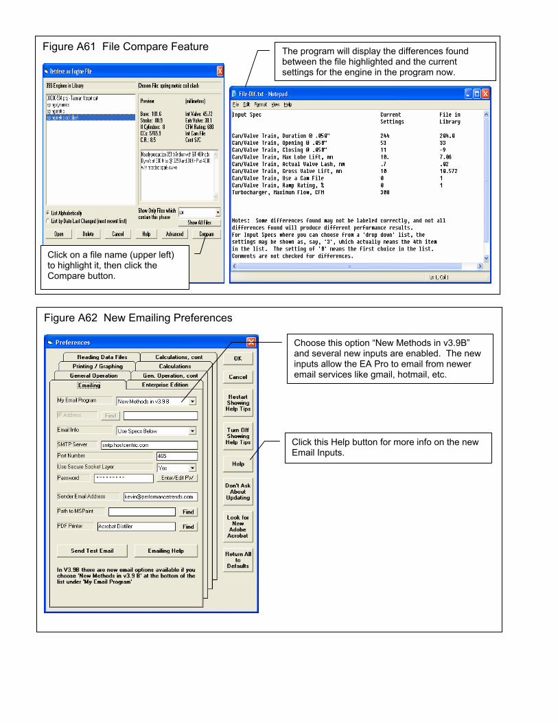
Figure A61 File Compare Feature
Click on a file name (upper left) to highlight it, then click the Compare button.
The program will display the differences found between the file highlighted and the current settings for the engine in the program now.
Figure A62 New Emailing Preferences
Choose this option “New Methods in v3.9B” and several new inputs are enabled. The new inputs allow the EA Pro to email from newer email services like gmail, hotmail, etc.
Click this Help button for more info on the new Email Inputs.
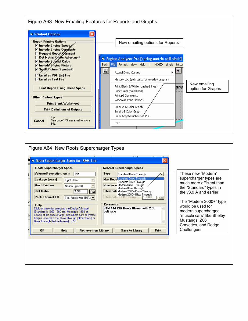
Figure A63 New Emailing Features for Reports and Graphs
New emailing options for Reports
New emailing option for Graphs
Figure A64 New Roots Supercharger Types
These new “Modern” supercharger types are much more efficient than the “Standard” types in the v3.9 A and earlier. The “Modern 2000+” type would be used for modern supercharged “muscle cars” like Shelby Mustangs, Z06 Corvettes, and Dodge Challengers.
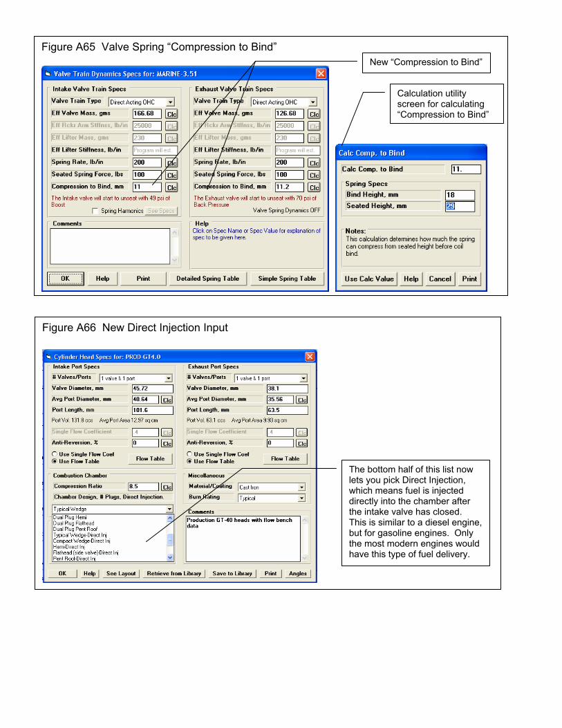
Figure A65 Valve Spring “Compression to Bind”
New “Compression to Bind”
Calculation utility screen for calculating “Compression to Bind”
Figure A66 New Direct Injection Input
The bottom half of this list now lets you pick Direct Injection, which means fuel is injected directly into the chamber after the intake valve has closed. This is similar to a diesel engine, but for gasoline engines. Only the most modern engines would have this type of fuel delivery.
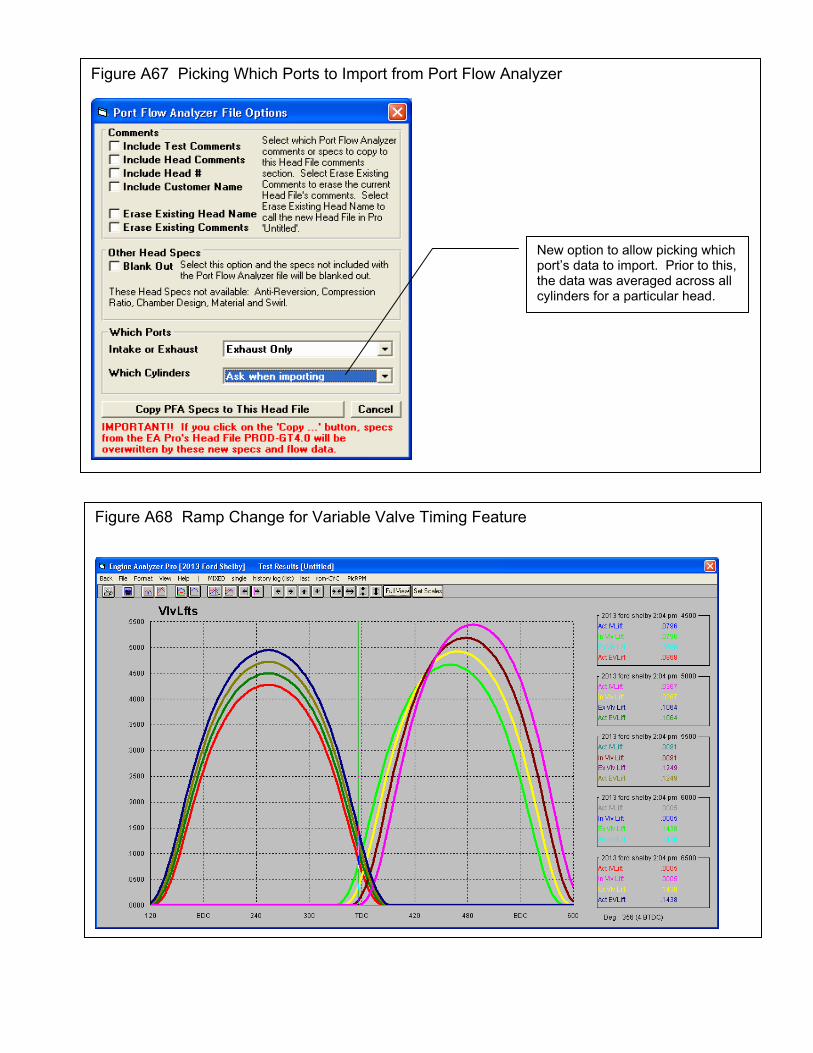
Figure A67 Picking Which Ports to Import from Port Flow Analyzer
New option to allow picking which port’s data to import. Prior to this, the data was averaged across all cylinders for a particular head.
Figure A68 Ramp Change for Variable Valve Timing Feature