appendix 13.2: initial site water management plan
TRANSCRIPT

6.13.2
Appendix 13.2: Initial Site Water Management Plan
River Humber Gas Pipeline Replacement Project
Under Regulation 5(2)(a) of the Infrastructure Planning (Applications: Prescribed Forms and Procedure) Regulations 2009
D O
C U
M E
N T
Application Reference: EN060004
April 2015
Environmental Statement Volume 6 Environmental Statement Document 6.13.2
The River Humber Gas Pipeline Replacement Project Page i
CONTENTS
Tables ....................................................................................... iii Figures ...................................................................................... iii DCO Documents Referenced .................................................... iii Abbreviations ............................................................................ iv Glossary .................................................................................... v 1 Executive Summary .......................................................... 1 2 Introduction ....................................................................... 2
2.1 Overview .................................................................. 2 2.2 Objective .................................................................. 3 2.3 Terminology.............................................................. 3 2.4 Guidance .................................................................. 3
3 Site Activities where Water will be used ........................... 5 4 Sources of Water that are Available and the Activities
that they can be used for .................................................. 7 4.1 Overview .................................................................. 7 4.2 Methods of Sustainable Management of Water
Sources .................................................................... 8 5 Consideration of Local Water Resources and the
Catchment Situation ....................................................... 11 5.1 Site Elevation ......................................................... 11 5.2 Local Water Resources .......................................... 11 5.3 Catchment Situation ............................................... 11
6 Permits ........................................................................... 13 7 Managing and Monitoring Water ..................................... 15
7.1 Surface Water Management .................................. 15 7.2 Fluvial and Coastal Floodwater Management ........ 16 7.3 Groundwater Management ..................................... 18 7.4 Construction Water Management ........................... 19 7.5 Planning for the Management of a Flood Incident .. 19
8 Planning the Scheme to Reduce Pollution ...................... 20 8.1 Overview ................................................................ 20 8.2 Pollution Prevention Guidance ............................... 20
9 Contingency Planning and Sensitivity Testing ................ 23 10 Efficient Site Welfare Facilities and Plan ........................ 24
10.1 Site Welfare Facilities ............................................. 24

Environmental Statement Volume 6 Environmental Statement Document 6.13.2
The River Humber Gas Pipeline Replacement Project Page ii
10.2 Plant and Equipment .............................................. 24 10.3 Maintenance ........................................................... 25
11 Training and Awareness Plan ......................................... 26 11.1 Water Resources .................................................... 26 11.2 Water and Risk Management ................................. 26
12 References ..................................................................... 27

Environmental Statement Volume 6 Environmental Statement Document 6.13.2
The River Humber Gas Pipeline Replacement Project Page iii
Tables
Table Title
Table 3-1 Key site activities that will use water
Table 4-1 Key options for water sustainability
Table 6-1 Water related consents, licences, permits and regulatory requirements
Table 8-1 Key pollution prevention guidance
Figures
Figure Number Title
Figure 4-1 Location of Goxhill and Paull sites in respect of key water features (Thorngumbald Drain in dark blue solid line; East Halton Beck in light blue solid line)
DCO Documents Referenced
DCO Document Reference
Title of Document
5.2 Flood Risk Assessment (Flood Incident Response Plan appended)
6.2 Chapter 2: Scheme Description
6.13 Chapter 13: Water Resources
6.13.3 Appendix 13.3: Hydrogeological Impact Assessment
7.2 Transport Assessment
7.2.1 Initial Traffic Management Plan
7.3 Initial Construction Environmental Management Plan

Environmental Statement Volume 6 Environmental Statement Document 6.13.2
The River Humber Gas Pipeline Replacement Project Page iv
Abbreviations
AEP Annual Exceedance Probability
AGI Above Ground Installation
BSI British Standards Institute
CAMS Catchment Abstraction Management Strategy
CEMP Construction Environmental Management Plan
CIRIA Construction Industry Research and Information Association
COSHH Control of Substances Hazardous to Health
DMRB Design Manual for Roads and Bridges
EA Environment Agency
FIRP Flood Incident Response Plan
FRA Flood Risk Assessment
HIA Hydrogeological Impact Assessment
MMO Marine Management Organisation
MWC Main Works Contractor
NELDB North East Lindsey Drainage Board
NPPF National Planning Policy Framework
NTS National Transmission System
PEMP Project Environmental Management Plan
PPG Pollution Prevention Guidelines
SAC Special Area of Conservation
SHIDB South Holderness Internal Drainage Board
SPA Special Protection Area
SuDS Sustainable Urban Drainage Systems
TBM Tunnel Boring Machine
TMP Traffic Management Plan
WFD Water Framework Directive
WTL Water Technology List

Environmental Statement Volume 6 Environmental Statement Document 6.13.2
The River Humber Gas Pipeline Replacement Project Page v
Glossary
Term Description
Above Ground Installation
Assets associated with buried gas pipelines, including structures and engineering that are located above ground to enable the operation and maintenance of the pipeline.
Abstraction Removal of water from surface water or groundwater, usually by pumping.
Aquifer A body of permeable rock that is capable of storing significant quantities of water; is underlain by impermeable material, and through which groundwater moves.
Bund A barrier, dam or mound used to contain or exclude water (or other liquids). Can either refer to a bund made from earthworks material, sand etc. or a metal/concrete structure surrounding, for example, a fuel tank.
Collisions Road accident in which one or more people are injured.
Construction Environmental Management Plan
A site specific plan developed to ensure that appropriate environmental management practices are followed during the construction phase of a project.
Construction Traffic Management Plan
The purpose of a construction traffic management plan is to anticipate traffic impacts associated with constructing activities of a scheme and outline appropriate mitigation measures which could be implemented.
Controlled Waters
These are fully defined in Section 104 of the Water Resources Act 1991. They include in summary:
1. Relevant territorial waters which extend seaward for three miles from the low-tide limit from which the territorial sea adjacent to England and Wales is measured.
2. Coastal waters from the low-tide limit to the high-tide limit or fresh-water limit of a river or watercourse.
3. Inland freshwaters.
Design Manual for Roads and Bridges
A series of 15 volumes that provide official standards, advice notes and other documents relating to the design, assessment and operation of trunk roads, including motorways in the United Kingdom.
Dewatering (groundwater control)
The removal of groundwater/surface water to lower the water table or to empty an area, such as an excavation, of water.
Early medieval period
AD410 to 1066.

Environmental Statement Volume 6 Environmental Statement Document 6.13.2
The River Humber Gas Pipeline Replacement Project Page vi
Term Description
Ecology The study of interactions between organisms and their environment.
Environmental Statement
Document that reports the findings of an Environmental Impact Assessment.
Flood Risk Assessment
An assessment of flood risk from all sources to a development and the mitigation of that risk
Feature Particularly prominent or eye-catching elements in the landscape, such as tree clumps, church towers or wooded skylines or a particular aspect of the project proposal.
Groundwater Defined by the European Commission groundwater Directive (80/68/EEC) as "all water which is below the surface of the ground in the saturation zone and in direct contact with the ground or subsoil".
Hydrogeology The branch of geology that deals with water below the ground surface.
Hydrostatic Test A way in which pressure such as pipelines can be tested for strength and leaks. The test involves filling the vessel or pipe system with a liquid, usually water, to a pressure exceeding that seen during operation.
Internal Drainage Boards
An Internal Drainage Board is a type of operating authority which is established in areas of special drainage and is defined by water catchment areas. An Internal Drainage Board has permissive powers to carry out flood defence works for ordinary watercourses at their discretion.
Land Drainage Artificial installation of land drainage to remove surplus water enabling farmers to cultivate and farm the land over a wider time period.
Main Works Contractor
Main contractor who will undertake detailed design and construction.
Outfall End of a temporary or permanent pipe from which water (or other effluent) is discharged. Can refer either to the end of a length of pipe or to a dedicated structure.
Pathway The route by which potential contaminants may reach receptors.
Pillow tank A tank used to store liquids which when full takes the shape of a large pillow.
Pollution Pathway
The retraceable route of a pollutant, from its source, through its interactions with the environment, and finally to its effect upon a target ecosystem or organisms.
Pollution Prevention Guidelines
Best practice guidelines set out by the Environment Agency to advise industry and public on legal responsibilities and good environmental practice.

Environmental Statement Volume 6 Environmental Statement Document 6.13.2
The River Humber Gas Pipeline Replacement Project Page vii
Term Description
Receptor Any defined feature that is sensitive to or has the potential to be subject to an effect.
Site of Special Scientific Interest
Sites of Special Scientific Interest are sites of national interest for nature conservation, geology or geomorphology designated under Section 28 of the Wildlife and Countryside Act 1981.
Source The activity or process producing a hazardous substance or contaminant that may adversely impact a receptor via a pathway.
Special Area of Conservation
Special Areas of Conservation are areas which have been given special protection under the European Commission’s Habitats Directive (92/43/EEC).
Special Protection Area
Special Protection Areas are strictly protected sites classified in accordance with Article 4 of the European Commission’s Birds Directive (2009/147/EC).
Surface Water Water that appears on the land surface that has not seeped into the ground, i.e. lakes, rivers, streams, standing water, ponds, precipitation.
Initial Traffic Management Plan
Plan is a contractual requirement and assesses the effects of the construction traffic on the local areas around the construction sites and identifies mitigating actions prior to the appointment of the Main Works Contractor and the finalisation of the Construction Traffic Management Plan.
Tranquillity A state of calm and quietude associated with peace, considered to be a significant asset of landscape.
Transect A set path used to count and record occurrences of a particular species (e.g. bats). It is standardised so that it is repeatable.
Tree Preservation Order
An order made under the Town and Country Planning Act 1990 to protect trees.
Tunnel Boring Machine
A machine used to excavate tunnels through varying types of strata.
Unexploded Ordnance
Unexploded ordnance are explosive weapons (bombs, shells, grenades, land mines, naval mines, etc.) that did not explode when they were employed and still pose a risk of detonation, potentially many decades after they were used or discarded.
Vantage Point A position or standpoint from which something is viewed or considered.

Environmental Statement Volume 6 Environmental Statement Document 6.13.2
The River Humber Gas Pipeline Replacement Project Page viii
Term Description
Visual Amenity The overall pleasantness of the views people enjoy of their surroundings, which provides an attractive visual setting or backdrop for the enjoyment of activities of the people living, working, recreating, visiting or travelling through an area.
Visual Receptors People with views of the development or associated activities. These are located within the zone of theoretical visibility and are typically residents, motorists, pedestrians, recreational users in residential areas on publicly accessible roads, footpaths and open spaces.
Watching brief The watching of a situation by a suitably qualified person to ensure that works (e.g. an excavation) are being done correctly.
Wind rose A diagram showing the relative frequency of wind directions at a place.
World Heritage Site
Places of 'outstanding universal value' selected by the United Nations Educational, Scientific and Cultural Organisation. Sites can be selected because they contain important cultural or natural features.
Zone of Influence The area/resources that may be affected by the biophysical changes caused by activities associated with a project.
Zone of Visual Influence
This is the area within which activities of the Scheme, whether temporary or permanent are likely to be visible.

Environmental Statement Volume 6 Environmental Statement Document 6.13.2
The River Humber Gas Pipeline Replacement Project Page 1
1 Executive Summary 1.1.1 National Grid Gas is proposing to construct and operate a replacement high
pressure transmission gas pipeline and associated infrastructure (Scheme) from Goxhill Above Ground Installation to Paull Above Ground Installation beneath the Humber Estuary.
1.1.2 Hyder Consulting (UK) Limited has been appointed by National Grid Gas to prepare an Initial Site Water Management Plan for the Scheme. This Initial Site Water Management Plan sets out a framework for planning the most efficient use of water within the Scheme. In addition, the Initial Site Water Management Plan outlines the environmental risks associated with the Scheme activities and considers appropriate methods to mitigate against these risks; in particular the risk of water pollution.
1.1.3 This Initial Site Water Management Plan would be developed by the Main Works Contractor (MWC), following their appointment, during the detailed design and construction phases of the Scheme.

Environmental Statement Volume 6 Environmental Statement Document 6.13.2
The River Humber Gas Pipeline Replacement Project Page 2
2 Introduction
2.1 Overview
2.1.1 National Grid Gas (the Applicant) is proposing to construct a replacement gas pipeline under the Humber Estuary to ensure the long term security of the Feeder 9 Gas Transmission Pipeline. The river bed cover over the Existing No 09 Crossing is currently being eroded by the Humber Estuary. The Feeder 9 pipeline carries a high level of importance within the National Transmission System (NTS) as a strategic pipeline conveying significant volumes of natural gas away from the Easington Importation Terminal south towards the Hatton Compressor Facility.
2.1.2 National Grid Gas is therefore proposing to replace the section of the Feeder 9 pipeline under the Humber Estuary with the construction of a new pipeline crossing, hereinafter referred to as the Scheme.
2.1.3 The Scheme would comprise a new high pressure gas pipeline installed within a bored tunnel that would run between the existing Goxhill Above Ground Installation (AGI) on the south bank of the Humber Estuary within North Lincolnshire to the Paull AGI on the north bank within the East Riding of Yorkshire.
2.1.4 The total length of the pipeline route would be up to 6km from the Goxhill AGI to the Paull AGI. The tunnel would be 5.03km and the crossing of the Humber Estuary 3km. Approximately 120m of new pipeline would be laid onshore at Goxhill from the Goxhill AGI to the start of the tunnelled section and approximately 400m would be laid onshore at Paull to connect the new pipeline into Paull AGI.
2.1.5 The MWC would be contractually obliged to take responsibility for the finalisation of this Initial Site Water Management Plan. It would be submitted to the EA for comment. This is a DCO requirement.
2.1.6 The Initial Site Water Management Plan has been requested by the EA in order to demonstrate that effective pollution control measures would be put in place, alongside appropriate water planning and management measures, for the Scheme. This would ensure that there would not be a deterioration of surface and ground water quality or the quantity of surface and ground water on either side of the Humber, in line with the Water Framework Directive (WFD). The preparation of this document is also a contractual requirements by National Grid Gas.
2.1.7 The Initial Site Water Management Plan has been informed by the findings of a detailed Flood Risk Assessment (FRA) (Hyder 2015a) (Development Consent Order (DCO) Document Reference 5.2), the geotechnical site investigation and the Hydrogeological Impact Assessment (HIA) (DCO Document Reference 6.13.3). The FRA also includes a Flood Incident Response Plan (FIRP) (Hyder, 2015b), as an Appendix, which has been developed for the Scheme in order to manage the risk of flooding from coastal, fluvial and artificial (e.g. lagoons, storage tanks) sources during the construction phase. The FRA and FIRP

Environmental Statement Volume 6 Environmental Statement Document 6.13.2
The River Humber Gas Pipeline Replacement Project Page 3
specifically deal with the issue of flooding and this is, therefore, not covered in detail in this Initial Site Water Management Plan.
2.2 Objective
2.2.1 The Initial Site Water Management Plan sets out a framework for planning the most efficient use of water within the Scheme. In addition, the Initial Site Water Management Plan outlines the environmental risks associated with the Scheme activities and considers appropriate methods to mitigate against these risks; in particular the risk of water pollution.
2.3 Terminology
2.3.1 Flood risk is a product of both the likelihood and consequence of flooding. Throughout this report, flood events are defined according to their likelihood of occurrence. Flood events are described according to an ‘annual chance’ of their occurrence, meaning the chance of a particular flood occurring in any one year. This is directly linked to the probability of a flood. For example, a flood with an annual chance of 1 in 100 (a 1 in 100 chance of occurring in any one year on average), has an annual exceedance probability (AEP) of 1%.
2.4 Guidance
2.4.1 Guidance outlined in the following documents would be used to inform the Site Water Management Plan prepared by the MWC for the Scheme:
A detailed Project Environmental Management Plan (PEMP) (this would be a development from the Initial Construction Environmental Management Plan (CEMP) (DCO Document Reference 7.3) and would be prepared by the MWC).
Pollution Prevention and Control Plan.
Sustainable Procurement Plan.
Materials Management Plan.
Reinstatement Plan.
Energy Reduction Plan.
Emergency Response/Spill Response Plan.
Refuelling Procedure.
Flood Risk Management Plan (a FIRP has been prepared as part of the FRA, DCO Document Reference 5.2).
Construction Traffic Management Plan (TMP) (an initial document has been prepared, DCO Document Reference 7.2.1).
Design Manual for Roads and Bridges (DMRB) Volume 11, Section 3, Part 10 (HD 45/09) (Highways Agency 2009).
Pollution Prevention Guidelines (EA 2014), various publication dates (accessed via http://www.netregs.gov.uk).
Environmental Statement Volume 6 Environmental Statement Document 6.13.2
The River Humber Gas Pipeline Replacement Project Page 4
National Planning Policy Framework (NPPF) (Department for Communities and Local Government, 2012).
Groundwater protection: Principles and practice, August 2013 Version 1.1 (EA 2013).
C650 Environmental Good Practice on Site (Construction Industry Research and Information Association (CIRIA) 2005).
C532 Control of Water Pollution from Construction Sites (CIRIA 2001).
Code of Practice for Earthworks (BS6031) (British Standards Institute (BSI) 2009).
Hydrogeological impact appraisal for dewatering abstractions. Science Report – SC040020/SR1 (EA April 2007a).
C515 Groundwater control – design and practice (CIRIA 2000).
R113 Control of groundwater for temporary works (CIRIA 1986).
Hydrogeological impact appraisal for groundwater abstractions. Science Report – SC040020/SR2 (EA 2007b).

Environmental Statement Volume 6 Environmental Statement Document 6.13.2
The River Humber Gas Pipeline Replacement Project Page 5
3 Site Activities where Water will be used 3.1.1 Table 3-1 identifies the key activities where water is required during the
construction phase of the Scheme. An assessment of whether a non-potable or potable source might be appropriate for each activity is also made.
3.1.2 The key activities outlined in Table 3-1 are indicative and these would be developed by the MWC in order to satisfy the Scheme design requirements.
3.1.3 The MWC would develop anticipated water demand figures for key site activities. For the anticipated water requirements for hydrostatic testing refer to Chapter 2: Scheme Description (DCO Document Reference 6.2).
Table 3-1 Key site activities that will use water
Activity Water Use (Obligatory to maintain operations)
Source: Potable or Non-Potable
Site Cabin Related Activities
Drinking, kitchen, canteen. Potable
Toilets and urinals, showers and hand washing.
Non-potable
Drainage Flushing. Both
General Cleaning Tool rinsing, boot washing, plant and equipment washing.
Non-potable
Site Dust Suppression
Dampening (bowsers) and Misting
Non-potable
Drilling Lubricant. Potable (if pressure required)
Tunnelling (Slurry Tunnel Boring Machine (TBM))
Slurry TBM requires supporting fluid.
Potable (if pressure required)
Hydrostatic testing Water tankered in to verify pipeline integrity. There is a possibility that water may be sourced from dewatering (groundwater control) and/or from an abstraction from the Thorngumbald Drain.
Potable (if pressure required) Non-potable (sourced from the dewatering or an abstraction from the Thorngumbald Drain)
Flooding of the tunnel annulus
Water (sea) to be used to fill tunnel.
Non-potable (sourced from the Humber Estuary)
Frame/Building Concrete cooling. Non-potable
Concrete Blocks Silo mixer. Both
Screed Laying. Both
Concrete Production Concrete production. Both, following guidance in EN1008:2002

Environmental Statement Volume 6 Environmental Statement Document 6.13.2
The River Humber Gas Pipeline Replacement Project Page 6
Activity Water Use (Obligatory to maintain operations)
Source: Potable or Non-Potable
Concrete Wash Out Concrete Wash Out Non-potable
Commissioning Mechanical and Electrical, Pipe, Pools, Bund Testing.
Potable for pipe systems (reuse to be considered) Tanks – 1st test non-potable; final test potable (with reuse)

Environmental Statement Volume 6 Environmental Statement Document 6.13.2
The River Humber Gas Pipeline Replacement Project Page 7
4 Sources of Water that are Available and the Activities that they can be used for
4.1 Overview
4.1.1 As identified in Table 3-1, there are non-potable and potable sources of water required during the construction phase of the Scheme. A riverine source of water from East Halton Beck (Figure 4-1) has been scoped out as a potential source of water owing to its limited flows as outlined in the Grismby, Ancholme and Louth Catchment Abstraction Management Strategy (CAMS). However, water may potentially be abstracted from Thorngumbald Drain, Figure 4-1. This has been identified in Chapter 13: Water Resources (DCO Document Reference 6.13).
Figure 4-1 Location of Goxhill and Paull sites in respect of key water features (Thorngumbald Drain in dark blue solid line; East Halton Beck in light blue solid line)
4.1.2 The key sources of water are summarised as follows:
Potable Sources
Water will be supplied to the construction site by tanker.
Goxhill Site Paull Site
Humber Estuary
Environmental Statement Volume 6 Environmental Statement Document 6.13.2
The River Humber Gas Pipeline Replacement Project Page 8
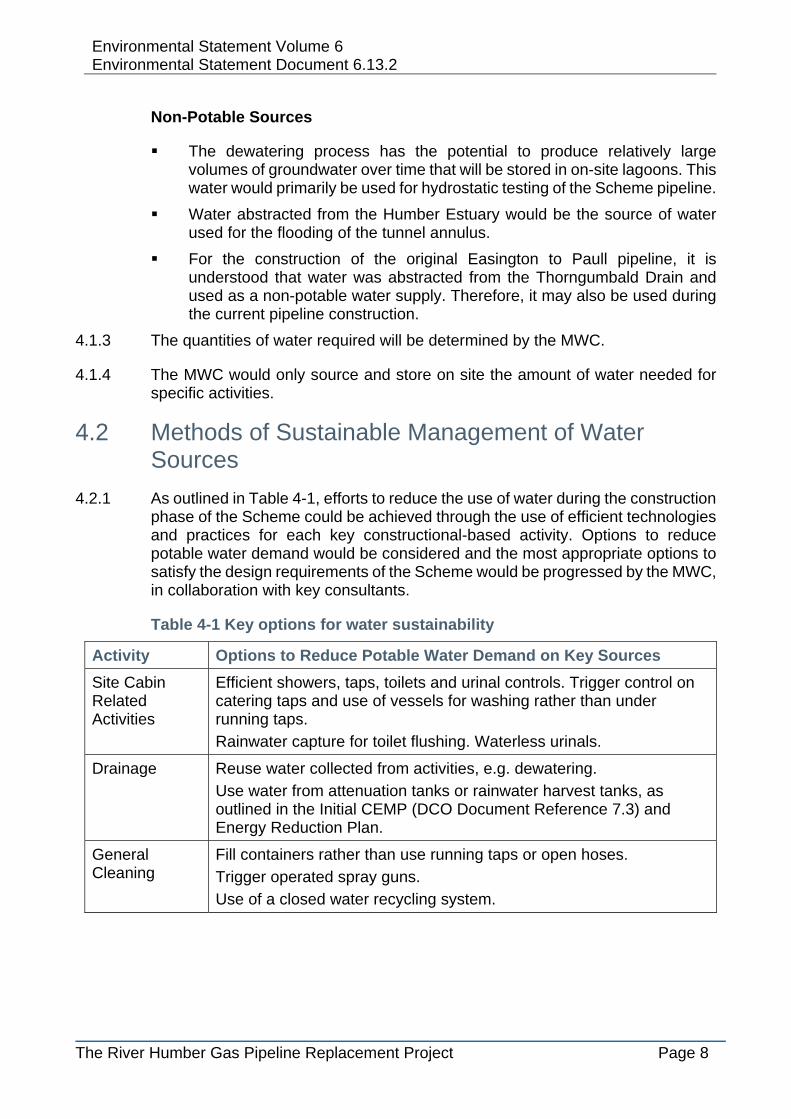
Non-Potable Sources
The dewatering process has the potential to produce relatively large volumes of groundwater over time that will be stored in on-site lagoons. This water would primarily be used for hydrostatic testing of the Scheme pipeline.
Water abstracted from the Humber Estuary would be the source of water used for the flooding of the tunnel annulus.
For the construction of the original Easington to Paull pipeline, it is understood that water was abstracted from the Thorngumbald Drain and used as a non-potable water supply. Therefore, it may also be used during the current pipeline construction.
4.1.3 The quantities of water required will be determined by the MWC.
4.1.4 The MWC would only source and store on site the amount of water needed for specific activities.
4.2 Methods of Sustainable Management of Water Sources
4.2.1 As outlined in Table 4-1, efforts to reduce the use of water during the construction phase of the Scheme could be achieved through the use of efficient technologies and practices for each key constructional-based activity. Options to reduce potable water demand would be considered and the most appropriate options to satisfy the design requirements of the Scheme would be progressed by the MWC, in collaboration with key consultants.
Table 4-1 Key options for water sustainability
Activity Options to Reduce Potable Water Demand on Key Sources
Site Cabin Related Activities
Efficient showers, taps, toilets and urinal controls. Trigger control on catering taps and use of vessels for washing rather than under running taps.
Rainwater capture for toilet flushing. Waterless urinals.
Drainage Reuse water collected from activities, e.g. dewatering.
Use water from attenuation tanks or rainwater harvest tanks, as outlined in the Initial CEMP (DCO Document Reference 7.3) and Energy Reduction Plan.
General Cleaning
Fill containers rather than use running taps or open hoses.
Trigger operated spray guns.
Use of a closed water recycling system.
Environmental Statement Volume 6 Environmental Statement Document 6.13.2
The River Humber Gas Pipeline Replacement Project Page 9
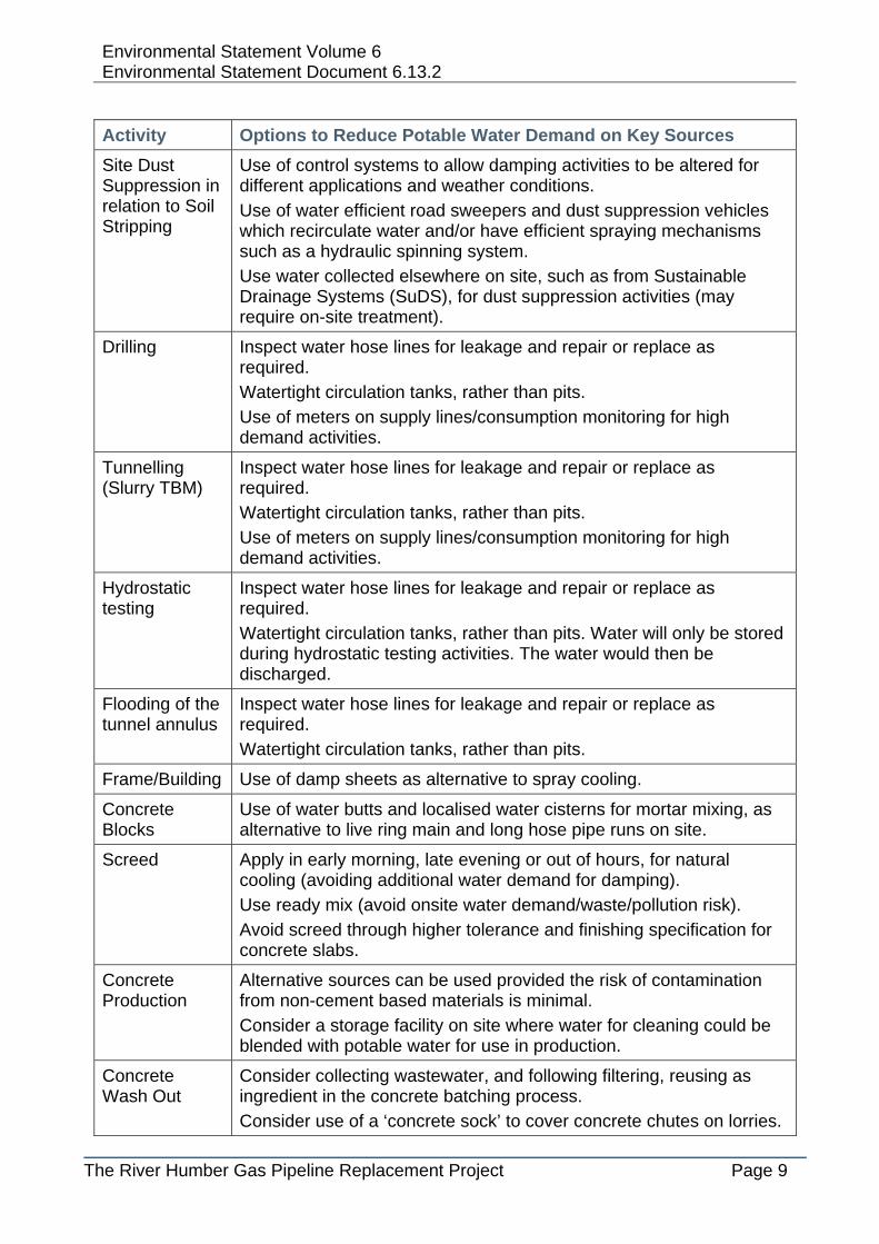
Activity Options to Reduce Potable Water Demand on Key Sources
Site Dust Suppression in relation to Soil Stripping
Use of control systems to allow damping activities to be altered for different applications and weather conditions.
Use of water efficient road sweepers and dust suppression vehicles which recirculate water and/or have efficient spraying mechanisms such as a hydraulic spinning system.
Use water collected elsewhere on site, such as from Sustainable Drainage Systems (SuDS), for dust suppression activities (may require on-site treatment).
Drilling Inspect water hose lines for leakage and repair or replace as required.
Watertight circulation tanks, rather than pits.
Use of meters on supply lines/consumption monitoring for high demand activities.
Tunnelling (Slurry TBM)
Inspect water hose lines for leakage and repair or replace as required. Watertight circulation tanks, rather than pits.
Use of meters on supply lines/consumption monitoring for high demand activities.
Hydrostatic testing
Inspect water hose lines for leakage and repair or replace as required.
Watertight circulation tanks, rather than pits. Water will only be stored during hydrostatic testing activities. The water would then be discharged.
Flooding of the tunnel annulus
Inspect water hose lines for leakage and repair or replace as required.
Watertight circulation tanks, rather than pits.
Frame/Building Use of damp sheets as alternative to spray cooling.
Concrete Blocks
Use of water butts and localised water cisterns for mortar mixing, as alternative to live ring main and long hose pipe runs on site.
Screed Apply in early morning, late evening or out of hours, for natural cooling (avoiding additional water demand for damping).
Use ready mix (avoid onsite water demand/waste/pollution risk).
Avoid screed through higher tolerance and finishing specification for concrete slabs.
Concrete Production
Alternative sources can be used provided the risk of contamination from non-cement based materials is minimal.
Consider a storage facility on site where water for cleaning could be blended with potable water for use in production.
Concrete Wash Out
Consider collecting wastewater, and following filtering, reusing as ingredient in the concrete batching process.
Consider use of a ‘concrete sock’ to cover concrete chutes on lorries.

Environmental Statement Volume 6 Environmental Statement Document 6.13.2
The River Humber Gas Pipeline Replacement Project Page 10
Activity Options to Reduce Potable Water Demand on Key Sources
Use trigger guns on hoses.
Commissioning Planned water use – sequential flushing, sub-valving and reuse where practicable.
Isolate water flows as soon as water turns clear when commissioning pipes and systems.
Use of tanks for storage /use in landscaping works or other.

Environmental Statement Volume 6 Environmental Statement Document 6.13.2
The River Humber Gas Pipeline Replacement Project Page 11
5 Consideration of Local Water Resources and the Catchment Situation
5.1 Site Elevation
5.1.1 Existing ground elevations on the Goxhill site generally vary between 1.5mAOD and 2.4mAOD, with 1.9mAOD being typical. On the Paull site the ground levels vary between 1.7mAOD and 2.7mAOD, with 2.0mAOD being typical.
5.2 Local Water Resources
5.2.1 In addition to the Humber Estuary, there are two key watercourses; the Thorngumbald Drain and the East Halton Beck, which are designated as EA Main Rivers. There is also a network of drainage ditches that are managed by the North East Lindsey Drainage Board (NELDB), on the southern side of the Humber. These drains facilitate drainage of the flat low lying land.
5.2.2 The East Halton Beck discharges to the Humber Estuary by gravity at East Halton Skitter. Flood conditions in the lower reaches of the Beck are strongly influenced by the tidal conditions, with floodwater ponding while the outfall is tide-locked. There are no significant flood defences along the East Halton Beck so the surrounding land begins to flood when fluvial floodwater levels rise above bank level.
5.2.3 It is understood that the Thorngumbald Drain discharges to the Humber Estuary by gravity, immediately south of the Paull site. There is also a Pumping Station which lifts water to the Humber when the drain is tide-locked.
5.3 Catchment Situation
5.3.1 The Grimsby, Ancholme and Louth Catchment Abstraction Management Strategy (CAMS) sets out the management of water abstraction (EA, 2013a) in the area of the Scheme, at the Goxhill site. The Goxhill site is located specifically within the Barrow Beck and Skitter Beck area of this CAMS.
5.3.2 The Hull and East Riding Abstraction Licensing Strategy (EA, 2013b) similarly sets out the management of water in the area of the Scheme, at the Paull site.
5.3.3 CAMS set out how local water resources will be managed within a catchment and contribute to implementing the main objectives of the Water Framework Directive (WFD); in particular in protecting and enhancing the water environment through the use of water sources for economic and social development.
5.3.4 A number of rivers in the locality of the Scheme and within the designated Grimsby, Ancholme and Louth CAMS area, drain into the Humber Estuary, which is an internationally important conservation site designated as a Special Protection Area (SPA), a Special Area of Conservation (SAC) and a Ramsar Wetland of international importance.

Environmental Statement Volume 6 Environmental Statement Document 6.13.2
The River Humber Gas Pipeline Replacement Project Page 12
5.3.5 The South Humber bank is covered by the Grimsby, Ancholme and Louth CAMS (EA, 2013a). The Scheme lies in Area B Barrow Beck and Skitter Beck (East Halton Beck). The CAMS status is no water available for abstraction except at extremely high flows. Groundwater resources in the Lincolnshire Chalk are fully committed to existing users and the environment. Within the Hydrogeological Impact Assessment (HIA) (DCO Document Reference 6.13.3), the relatively low pumping rate (70 m3/d) predicted for the drive pit dewatering and the short duration (approximately six weeks) is considered to be negligible in comparison to the 77,500 m3/d abstracted from this catchment, mostly for public water supply and industrial use. The drive pit dewatering would also take place in March and April when water resources are less stressed after winter recharge. However, it is acknowledged that water resources on the Goxhill side are in deficit and abstraction is generally not permitted so this would need to be discussed with the EA.
5.3.6 The North Humber bank is covered by the Hull and East Riding Abstraction Licensing Strategy (EA, 2013b). The resource status is ‘water available’ at very low flows (Q95) and higher flows i.e. consumptive abstraction is available at least 95% of the time. However, conditions may also be written into licences to ensure that abstraction stops if groundwater levels in the chalk aquifer fall too low. This would help to prevent saline water being drawn into the aquifer and reducing the quality of the groundwater. The groundwater abstraction rate at the reception pit is likely to be in the order 150 m3/d for the proposed groundwater control solution, as predicted within the HIA (DCO Document Reference 6.13.3). This abstraction rate is considered to be a negligible impact on the overall water resource status of the Hull and East Riding CAMS, especially as the abstraction is only planned to take 35 days (from 29/05/2018 – 02/07/2018). In accordance with the CAMS strategy for this catchment we recommend that baseline groundwater levels are monitored and compared to regional groundwater levels. This can be used to ensure that abstraction does not occur when groundwater levels in the chalk aquifer are at very low levels.

Environmental Statement Volume 6 Environmental Statement Document 6.13.2
The River Humber Gas Pipeline Replacement Project Page 13
6 Permits 6.1.1 Table 6-1 provides an outline of the types of water related consents required for
the Scheme. Where a consent, licence or permit has been supplied, the site (i.e. overseen by MWC) is required to operate within the relevant requirements.
Table 6-1 Water related consents, licences, permits and regulatory requirements
Type of Permission
Details Rationale Timing of Submission
Deemed Marine Licence
Licence required from the Marine Management Organisation (MMO) for abstraction of water from the Humber Estuary for flooding of the tunnel annulus, post-construction and for any discharge infrastructure below mean high water springs.
Application is required for works within the tidal estuary below the mean high water level.
A Deemed Marine Licence forms part of the DCO and the MWC would be required to adhere to these conditions.
Land Drainage Consent for work in Ordinary Watercourses
Consent from NELDB (Note: liaison has occurred with SHIDB to confirm that their consent is not required).
Application is required at locations where drainage ditches are crossed or culverted.
3 months prior to construction.
Permit for Discharges to Surface Water
Environmental Permit to be obtained from the EA.
Environmental Permit required under Schedule 22 of EPR 2010.
3 months prior to construction.
Consent to install the pipeline under, and work in, the Humber Estuary.
Flood Defence Consent from the EA
No further information
3 months prior to construction.
Consent to carry out construction work in a floodplain
Flood Defence Consent from the EA
No further information
3 months prior to construction.
Water Abstraction License
License required under Section 24,
Abstraction of groundwater for pit
4 months prior to construction.

Environmental Statement Volume 6 Environmental Statement Document 6.13.2
The River Humber Gas Pipeline Replacement Project Page 14
Type of Permission
Details Rationale Timing of Submission
Water Resources Act 1991
establishment and testing of the pipeline; abstraction from the Humber Estuary on Goxhill side for flooding of the tunnel. Required for abstraction volumes greater than 20 cubic metres of groundwater per day.
Surface Water Abstraction Licence
Water Resources Act, 1991 (as amended by the Water Act 2003), Environment Act 1995.
Proposed abstraction from Thorngumbald Drain.
To be confirmed by MWC
Groundwater Investigation Consent
S32 under the Water Resources Act 1991 (as amended by the Water Act 2003), Environment Act 1995
No further information
To be confirmed by MWC
6.1.2 Appropriate procedures would be followed for surrendering permits, consents and licenses following the end of the construction phase.

Environmental Statement Volume 6 Environmental Statement Document 6.13.2
The River Humber Gas Pipeline Replacement Project Page 15
7 Managing and Monitoring Water
7.1 Surface Water Management
7.1.1 Flooding from surface water source is a potential risk during short, intense rain storm events or longer duration storms, when the capacity of underlying soils and drainage systems is exceeded and rainfall runs overland to pond in depressions within the landscape. It is therefore important that due consideration is given to changes in surface water runoff patterns as a result of the Scheme.
7.1.2 The construction site would cause temporary increases in the coverage of impermeable surfaces, in particular relating to the visitor spaces located within parking areas on the Goxhill and Paull sites. This has the potential to result in localised increases in the rates and volumes of rainfall runoff that are generated during rain storm events. If not appropriately managed this may present risks of flooding on-site or off-site in the wider catchment. In the absence of appropriate drainage management measures, this could also lead to an increase in flood water levels in receiving drainage ditches that run across both of the sites.
7.1.3 The following measures would be used by the MWC to manage surface water within the Scheme:
Pre-construction drainage would be installed to intercept the existing land drainage system and divert soil water away from the working areas.
Vehicle traffic would be limited to major path routes through the site to avoid soil compaction and the associated increased likelihood of surface water runoff.
SuDS would be used to ensure that there is no increase in runoff rates or volumes from the construction sites to the surrounding land drainage ditches and would also be used to manage surface water flood risk on the site.
Subject to appropriate consents, the SuDS would discharge to the local drains on the site. In the design of the SuDS for the site, 20%, 3.33% and 1% AEP rainfall events will be used to size the required measures and consultations will be undertaken with the NELDB, SHIDB and EA as appropriate to agree site runoff rates and if required methods of discharge to the adjacent network of drainage ditches.
The SuDS measures within the Scheme would include the use of:
a Stone and gravels (e.g. permeable hardcore) for the track working areas to reduce the overall area of impermeable surfaces and the effect on surface water flood risk. The permeable hardcore layer would also provide storage attenuation for the minor areas of impermeable surface on the sites (e.g. office and welfare cabins, parking areas etc.).
b A system of ditches, swales or small ponds that would manage and attenuate surface water runoff from all areas of the site (e.g. tracks, working areas, parking areas, spoil and waste storage areas).

Environmental Statement Volume 6 Environmental Statement Document 6.13.2
The River Humber Gas Pipeline Replacement Project Page 16
c Where required cross drainage pipes would be laid beneath access tracks on the site to maintain existing overland drainage pathways and prevent tracks impeding existing runoff routes (e.g. to prevent localised ponding on the site).
7.1.4 The parking areas (permeable hardcore and tarmac visitor bays) would form the largest area of impermeable surface on the Goxhill site (approximately 9,000m²) and Paull site (approximately 5,000m²).The indicative impermeable parking areas were calculated from DCO Document Reference 2.4. For the purpose of the runoff calculations, it is assumed that these parking areas would be 50% impermeable. Equivalent Greenfield run-off rates and associated storage requirements have been estimated for the proposed temporary parking areas. An additional volume of rainfall runoff equal to approximately 340m³ and 225m³ is therefore estimated to be generated as a result of the parking areas on the Goxhill and Paull sites respectively. The MWC will therefore need to provide 0.5 to 3m wide filter drains around the parking areas to provide sufficient attenuation storage to mitigate the increase in runoff. However, this would need to be reviewed based on the MWC’s temporary works layout.
7.1.5 The use of SuDS would ensure that the Scheme would not increase flood risk in line with Policy ENV4 of the Joint Structure Plan for Hull and East Riding saved policies (adopted 2005) (Hull City Council and East Riding of Yorkshire Council, 2005). The proposed SuDS features would also be used to improve surface water management in line with the Flood and Water Management Act, 2010 and reduce the potential impacts resulting from increases in the rates and volumes of surface water runoff. SuDS are considered suitable adaption measures against the impacts of the Scheme on the application site drainage (NPPF, 2012).
7.1.6 The drainage design would be developed by the MWC to support management of surface water on the construction site.
7.1.7 All SuDS features, in addition to new and existing field drains would be monitored by works staff to ensure blockages do not occur during the construction phase. A suitable monitoring programme would be implemented by the MWC, with records kept of any maintenance requirements to be undertaken on a reasonable timescale by a suitably qualified person.
7.1.8 A full checklist of monitoring required for the Scheme would be prepared by the MWC. This checklist would include as a minimum, the following:
Water quality monitoring at discharge points to local drains.
Visual inspections of ditches.
Visual inspection of joints along the pipe which will run to the outfall at East Halton Beck.
7.2 Fluvial and Coastal Floodwater Management
7.2.1 In order to protect vulnerable temporary infrastructure (e.g. drive pit, diesel generators) on the site from flooding, environmental design measures comprising 1.4m high flood bunds and raised platforms (to a height of 3.4mAOD) would be constructed around/under vulnerable infrastructure. These measures would

Environmental Statement Volume 6 Environmental Statement Document 6.13.2
The River Humber Gas Pipeline Replacement Project Page 17
protect the vulnerable infrastructure on the Goxhill site (located in areas of the site where the ground level is approximately 2mAOD) from flooding from a 0.5% AEP coastal event coinciding with a breach within the Humber Estuary defences (e.g. within the length of flood defences between East Halton Skitter and Halton Marshes) and a 1% AEP fluvial flood from the East Halton Beck.
7.2.2 The same temporary environmental design measures (1.4m high flood bunds and raised platforms (3.4mAOD)) would also be constructed on the Paull site to protect vulnerable infrastructure from flooding in a 0.5% AEP coastal event coinciding with a breach (less than 50m wide).
7.2.3 As confirmed within the FRA (Hyder, 2015a) (DCO Document Reference 5.2) the proposed bunds and raised platforms would ensure that vulnerable infrastructure would have the required standard of flood protection in line with NPPF guidelines.
7.2.4 Where required and subject to agreement with the landowner/occupier, new field drains would be installed to maintain the site work areas as dry as practicable and to aid recovery from the construction activities.
7.2.5 The perimeter of the lagoons used for the storage of discharges from the dewatering system would either be bunded by secondary bunds (designed and constructed to provide a flood barrier e.g. constructed from impermeable materials) or by double layered water storage pillows, in order to prevent flooding of the site in the event that there is a breach of the lagoons. Both the configuration of the lagoons and the secondary bunds are to be designed by the MWC.
7.2.6 Further management of water associated with the operation of the Scheme, for example the hydrostatic testing or flooding of the tunnel annulus, is described in detail in Section 7.4.
7.2.7 To ensure unrestrictive access for maintenance purposes to the watercourses on and around the construction compounds/working areas, a 10m buffer zone would be retained around all existing ditches, except where crossed by vehicle accesses or the pipeline. This measure will reduce the risk of harm to surface waters in line with Policy NAT7 of the Joint Structure Plan for Hull and East Riding saved policies (adopted 2005) and will reduce the risk of blockages which would impact on flood risk. This 10m buffer zone exceeds the distances outlined by Byelaws of 7m and 9m for the SHIDB and NELDB, respectively.
7.2.8 The FRA includes (as an Appendix) a FIRP (Hyder, 2015b) (DCO Document Reference 5.2) which has been developed for the Scheme in order to manage the risk of flooding from coastal, fluvial and artificial (e.g. lagoons, storage tanks) sources during the construction phase. This FIRP would be developed and finalised by the MWC.

Environmental Statement Volume 6 Environmental Statement Document 6.13.2
The River Humber Gas Pipeline Replacement Project Page 18
7.3 Groundwater Management
7.3.1 The tunnel, launch pit and reception pit would be kept reasonably dry during the construction of the tunnel and the installation of the pipeline by controlling groundwater inflow.
7.3.2 The Tunnel Boring Machine (TBM) would be a closed face system. Groundwater inflow into the tunnel during construction would be minimal and dealt with by normal sump pumping. As the TBM progresses the tunnel would be lined with pre-cast concrete rings and grouted in to the rock, so that groundwater would be excluded from the tunnel. The lining specification stipulates the leakage class rating of the tunnel, in this instance class 3; characterised as ‘capilliary dampness’, which is defined as having occasional damp patches on the tunnel lining, but no drops of water. The allowable daily leakage rate is 0.1 litres / metre squared. This class rating would also prevent any fines / materials from entering the tunnel.
7.3.3 Within the drive pit and reception pit, groundwater control could be achieved by combining four approaches; cut-off walls (secant and sheet piling), deep well dewatering, sump pumping and passive relief wells within the base of the pit. However, the detailed dewatering scheme would be designed and installed by a specialist dewatering contractor. The information below is based on a reference design only.
7.3.4 As part of the detailed design for groundwater control, the MWC would be required to produce a Contingency Action Plan (CAP) as part of the Site Water Management Plan. The CAP should identify management actions for scenarios including but not limited to the following:
Complaints about appearance of wastewater discharge
Unexpected contaminants found during monitoring
Failure of treatment methods
Failure of pumping systems
Excess groundwater seepage into construction area
Heavy rainfall
Impacts on the stability of adjacent structures
Release of any toxic materials
7.3.5 The CAP should include, but not necessarily be limited to the following actions:
Notification to the EA, as soon as possible
Determining the cause of any exceedances
Evaluation of location, likely scale, duration and effect
Identification of appropriate mitigation or remediation measures.
7.3.6 Potential solutions are to be identified by the Contractor in advance and an emergency preparedness plan drawn up.

Environmental Statement Volume 6 Environmental Statement Document 6.13.2
The River Humber Gas Pipeline Replacement Project Page 19
7.4 Construction Water Management
7.4.1 Water is required for the pre and post-installation hydrostatic testing, and in the flooding of the tunnel annulus. The water for the hydrostatic testing would be sourced from groundwater, tankered in or abstracted from the Thorngumbald Drain. A temporary storage facility would be constructed to commence the first test. The storage facility would be lined with impermeable membrane to prevent contamination and bunded to prevent spill risk. The exact size of the bunded area would be determined based on the volume of water being held in the temporary storage facility. Overpumping and re-use of water between test sections would reduce the amount of water required on site.
7.4.2 The design and construction of the storage facility bunds must meet appropriate regulations, and the MWC must prepare emergency procedures for potential bund failure. Visual inspections would be co-ordinated by the MWC to ensure that the bunds remain intact and are not damaged during construction.
7.4.3 Staff would familiarise themselves with the emergency contact details as provided in the FIRP (See Section 7.5) (DCO Document Reference 5.2) should bund failure occur.
7.4.4 In addition to the drive pit and reception pit, water may need to be removed from other excavations including the pipeline trench. This would be carried out using pumps and hoses. Such de-watering operations would be controlled by using a scafftag or tagging system (see below).
7.4.5 A scafftag or tagging system would be installed and regularly inspected by the MWC’s Environmental Manager. This system would comprise a register identifying all pumping operations, points of discharge, type of discharge, any mitigation requirements at discharge points, the plant tagged identification number, the responsible attendant, dates of discharge and permit numbers.
7.5 Planning for the Management of a Flood Incident
7.5.1 A FIRP (Hyder 2015b), provided as an appendix to the FRA (Hyder, 2015a) (DCO Document Reference 5.2) for the Scheme, has been developed for the site in order to manage the risk of flooding from coastal, fluvial and artificial (e.g. lagoons, storage tanks) sources.
7.5.2 The FIRP would link into the EA’s advanced flood warning system and temporary flood warning systems located on site. In the implementation of the FIRP, the on-site operatives would be able to assess the need to put evacuation and site shutdown procedures into action. The FIRP would be finalised by the MWC prior to the construction phase, and periodically reviewed throughout the construction phase.

Environmental Statement Volume 6 Environmental Statement Document 6.13.2
The River Humber Gas Pipeline Replacement Project Page 20
8 Planning the Scheme to Reduce Pollution
8.1 Overview
8.1.1 In addition to the management of floodwater risk, in the planning of the Scheme, due consideration would also be given to prevent the runoff of pollution and sediments from the site. This is because contaminated runoff has the potential to impact on the water quality of nearby receptors.
8.1.2 An assessment to determine that there would be no derogation of licensed or unlicensed groundwater and surface water abstractors is provided within Chapter 13: Water Resources (DCO Document Reference 6.13).
8.2 Pollution Prevention Guidance
8.2.1 Pollution Prevention Guidelines (PPGs), produced by the EA (2007), are based on current best practice and relevant legislation to inform in the management of pollution prevention. Table 8-1 summarises the relevant PPGs to the construction of the Scheme and how these can be addressed on site. This is not an exhaustive list and will need to be developed further by the MWC prior to construction.
Table 8-1 Key pollution prevention guidance
PPG 1: Understanding your environmental responsibilities – good environmental practices
Comment How would this be addressed on site?
Drain rainwater away from your premises efficiently to reduce flood risk.
Finalised Site Water Management Plan to be produced by MWC.
Consider what materials have been delivered, collected or stored on site.
Record materials on site.
Materials to be stored, handled and disposed of in accordance with Control of Substances Hazardous to Heath (COSHH) Regulations and COSHH Assessments carried out.
Provide suitable storage away from drains or watercourses and protect against fluvial flooding.
Keep materials secure on site to reduce the risk of accidental damage, vandalism, arson or theft.
Inspect storage areas and containers regularly to make sure a good condition is maintained.
PPG5: Works and maintenance in or near water
Plant washing can produce high volumes of silt. Consider methods of reducing silt pollution.
As in PPG13 Vehicle washing and cleaning, locate such facilities at least 10m away from watercourse or drains on site.
Designated area with either isolated drainage, settlement tank or sealed system.

Environmental Statement Volume 6 Environmental Statement Document 6.13.2
The River Humber Gas Pipeline Replacement Project Page 21
Excavation can cause silt pollution and potential contamination of water receptors
A contaminated land assessment has been conducted as part of the Ground Investigation Report to assess if any potential contaminants are present on site. Additional checks during excavation will identify any unexpected contamination. Silty water to be allowed to settle out before disposal through the use of lagoons. However, the use of lagoons is dependant on the volume of silt produced and where appropriate settling/inspection tanks will be utilised.
PPG6: Working at construction and demolition sites
Control of vehicular traffic to reduce pollution risk.
Initial Traffic Management Plan to be developed by MWC.
On site vehicles to use the designated running tracks.
Provide protection for vulnerable drains.
Bunds and oil/diesel traps to be provided where applicable, in order to mitigate against impacts on water quality of nearby watercourses. 10m buffer to be used where practicable.
PPG22: Dealing with spills
Provide measures for dealing with spillages.
Standard procedures would be outlined in a Pollution Prevention and Control Plan, as a contractual requirement for the MWC, to ensure that all staff are aware, in order to reduce the severity of spills should they occur. All incidences would be reported.
Spill kits would be provided at relevant locations across the site. Staff would be made aware of these.
8.2.2 The following paragraphs 8.2.3 to 8.2.18 highlight an incomplete list of the contents of an Environmental Management System. The MWC must have a suitable ISO14001 compliant Environmental Management System for all aspects of the site works to comply with any Environmental Permit conditions.
Specific Methods for preventing pollution from oil and other contaminants
8.2.3 The generator compound would include a concrete pad with a bund, bunded fuel tanks, oil/diesel traps and drains in order to mitigate against impacts on water quality of nearby watercourses. A minimum distance of 10m would be maintained between the generator compound and the water receptors.
8.2.4 As appropriate and in accordance with the re-fuelling procedure (to be developed by the Main Works Contractor), any transfer of fuel would only take place within a designated fuel transfer area. Drainage from this area would incorporate an isolation facility, such that the outlet could be sealed in the event of a spill. This would prevent pollutants reaching sensitive receptors, in particular the Thorngumbald Drain, South Pasture Drain, Pasture Drain, East Halton Beck and the drainage ditches that cross the site.

Environmental Statement Volume 6 Environmental Statement Document 6.13.2
The River Humber Gas Pipeline Replacement Project Page 22
8.2.5 Concrete for the construction of the base to the drive and reception pits, would only be laid following the suitable preparation of the ground surface and temporary shuttering would be used to contain potential leaks.
8.2.6 Designated washing out areas for concrete lorries would be constructed, with impermeable liners to protect the soil and groundwater.
8.2.7 Contaminated wash water, would be tankered off site for disposal at a licensed facility, to prevent adverse effects on the water quality of surface water receptors within the study area.
8.2.8 Visual inspections of key water resources within the application boundary would be undertaken by suitable staff members at suitable frequencies, as co-ordinated by the MWC, to identify issues that may affect the water quality of surface water receptors and that would therefore require remediation.
8.2.9 The inspection of water bodies would check for compliance with up to date water quality standards where available from the EA and as highlighted in guidance provided within the WFD.
8.2.10 Water sampling would be required prior to construction to ascertain baseline conditions for watercourses within the application boundary of the Scheme. A water sampling programme would be performed at set frequencies (at consented discharge outfalls) during the construction phase to ensure the adherence to water quality standards. Monitoring of the water receptors for pollution as a result of the Scheme would continue for two years post-construction. This has been pre-agreed as an EA requirement.
Methods for preventing pollution from sediment
8.2.11 The tunnel constructed to facilitate the installation of the pipeline would be flooded using sea water to protect the pipe from corrosion and sealed at both ends on completion of the pipeline.
8.2.12 The loosening of bed sediment associated with the abstraction of water from the Humber Estuary, for the flooding of the tunnel annulus, has the potential to affect water quality and sedimentation in the river and marine environment. To mitigate this impact, the installation of the lines at low tide would be facilitated by caged pumps, to keep them off the sediment bed. This would also avoid pulling silt into the pumps and ultimately the tunnel. Key guidance for the operation and maintenance of the caged pumps would be developed by the MWC to ensure mitigation against pollution caused by sediment.
8.2.13 The lagoons and filter drains, as well as being utilised primarily to reduce the risk of surface water flooding, would also function to settle any suspended sediments in the runoff from the site, preventing adverse effects on water quality of receiving watercourses which may result from loosened sediment during construction works. The design and location of the lagoon and filter drain features would be developed by the MWC. Where lagoons and filter drains are used to control surface water run-off, these would be maintained on a regular basis by the MWC.

Environmental Statement Volume 6 Environmental Statement Document 6.13.2
The River Humber Gas Pipeline Replacement Project Page 23
8.2.14 Also as part of the SuDS measures, surface water from the site would be passed through swales/ponds etc. before discharge and the outfall for discharge monitored in order to prevent adverse effects in water quality as a result of sediment contamination.
Methods for preventing pollution from waste and spoil
8.2.15 All materials stored on site would be recorded and safety requirements for the use and management of materials would been overseen by MWC and information shared with work staff. All storage would be in accordance with COSHH.
8.2.16 Suitable storage away from drains or watercourses would be provided on site. All materials, including spoil, would be kept secure.
8.2.17 All waste containers are required to be maintained in good condition to prevent the escape of waste and the ingress of water which could cause contamination of nearby receptors of the water environment. The MWC would ensure routine checks to evaluate the integrity of the storage containers.
8.2.18 The construction of the tunnel drive and reception pits would generate large volumes of spoil arisings, in addition to spoil slurry. However, through the use of the settlement lagoons and swales used to control surface water run-off and the construction of low level bunds around the boundary of the Scheme, spoil sediments would be prevented from reaching the nearby water receptors.
9 Contingency Planning and Sensitivity Testing 9.1.1 In the preparation of the finalised Site Water Management Plan by the MWC,
appropriate contingency planning and sensitivity testing should be undertaken to manage potential risks. This should be undertaken with reference to ‘Preventing Industrial and commercial pollution: pollution prevention pays.’ This publication includes advice on site drainage, handling and delivering materials, storage, waste management, trade effluent and emergency planning and response.
9.1.2 The MWC would need to take into account the potential risks associated with the proposed works when preparing the finalised Site Water Management Plan. Although not exhaustive, the potential risks of the proposed works include:
Hydrogeological uncertainties;
Water quality commitments;
Abstraction uncertainties;
Consents and licensing constraints;
Flood Risk - Fluvial, Coastal (Breach/Overtopping), Surface and Groundwater risk;
Assessment based on existing EA data and does not consider the potential for new data;
High level study FIRP only; and
Telemetry uncertainties.

Environmental Statement Volume 6 Environmental Statement Document 6.13.2
The River Humber Gas Pipeline Replacement Project Page 24
10 Efficient Site Welfare Facilities and Plan
10.1 Site Welfare Facilities
10.1.1 As outlined in Table 4-1, there are water efficiencies to be made in the selection of amenities for the site welfare facilities. Where appropriate these will be developed in line with the Energy Reduction Plan, by the MWC. Such amenities may include:
Toilets;
Wash hand basins;
Urinals;
Showers;
Catering and food preparation areas; and
Boot washing.
10.1.2 Site welfare facilities would use plumbed in water dispensers.
10.1.3 The most effective water efficiency methods for hand basins, which do not compromise potential performance of the appliance are:
The use of motion sensors; and
Installing taps with efficient flow patterns e.g. spray taps or aerated taps.
10.1.4 All new toilets would have a flushing volume of 6 litres or less to comply with Water Supply (Water Fittings) Regulations 1999. However, a number of more efficient options are now available including toilets that flush a maximum of 4.5 litres. Dual flush toilets are another sustainable, water saving option.
10.1.5 Good practice in the water efficiency of urinals involves installing a device to control the flushing based on how often the urinal is used. There are a number of options to achieve this, but good practice in the construction sector would usually involve the use of a low maintenance hydraulic valve. This can be fitted in the inlet pipework of the urinal system and does not require power to operate. Considerations should also be made for waterless urinals.
10.1.6 Multiple showers are to be installed as part of the welfare facilities and a flow rate of 6 to 8 litres per minute should be considered for water efficiency.
10.1.7 A trigger control to ensure auto-isolation of flow would be fitted to sink taps involved in food preparation or canteens. This will prevent taps being left running when not in use.
10.2 Plant and Equipment
10.2.1 The large majority of activities on site using water sources would inevitably involve plant or equipment. Water using activities have already been identified in Table 2-1. The frequency of use would be taken into account in the procurement process of such plant and equipment by the MWC.

Environmental Statement Volume 6 Environmental Statement Document 6.13.2
The River Humber Gas Pipeline Replacement Project Page 25
10.3 Maintenance
10.3.1 Welfare facilities would undergo on-going maintenance to ensure low water-use. In order to achieve this, basic checks can be carried out to ensure facilities are operating as designed through:
Checking that taps are not dripping;
Checking that percussion taps do not run for longer than necessary;
Ensuring the sensor driven taps and/or urinals are working correctly; and
Ensuring that toilets are not leaking through the overflow or valves.
10.3.2 Plant and equipment would each have individual maintenance requirements. The instruction provided with the equipment or from the hire company would be followed to ensure efficient water use.

Environmental Statement Volume 6 Environmental Statement Document 6.13.2
The River Humber Gas Pipeline Replacement Project Page 26
11 Training and Awareness Plan
11.1 Water Resources
11.1.1 Ensuring staff working on the site are aware of efficient, appropriate and safe water using practices and habits is critical to reducing wasted water during the construction phase on site.
11.1.2 Appropriate time would be set aside during the site induction to include training to all staff in the usage of water, with tool box talks and refresher training repeated in advance of high demand periods.
11.1.3 The MWC would consider monitoring the water footprint of the construction site to inform training and awareness of sustainable water practices.
11.2 Water and Risk Management
11.2.1 It is the responsibility of the MWC to ensure that all staff working on site are aware and receive relevant training in the management of the risk of flooding. Further information regarding evacuation procedures are outlined in the FIRP within the FRA (DCO Document Reference 5.2).
Environmental Statement Volume 6 Environmental Statement Document 6.13.2
The River Humber Gas Pipeline Replacement Project Page 27
12 References British Standards Institution (BSI), (2009). Code of Practice for Earthworks (BS6031).
CIRIA (1986). R113 Control of groundwater for temporary works.
CIRIA (2000). C515 Groundwater control – design and practice.
CIRIA (2005). C650 Environmental Good Practice on Site (Construction Industry Research and Information Association.
CIRIA (2001). C532 Control of Water Pollution from Construction Sites.
Department for Communities and Local Government (2012). National Planning Policy Framework.
Environment Agency (2007). Pollution Prevention Guidelines.
Environment Agency (2007a). Hydrogeological impact appraisal for dewatering abstractions. Science Report – SC040020/SR1.
Environment Agency (2007b). Hydrogeological impact appraisal for groundwater abstractions. Science Report – SC040020/SR2.
Environment Agency (2013a). Grimsby, Ancholme and Louth Catchment Abstraction Management Strategy.
Environment Agency (2013b). Hull and East Riding Abstraction Licensing Strategy.
Environment Agency (various). Pollution Prevention Guidelines Available at: http://www.netregs.gov.uk (online).
Environment Agency (2013). Groundwater protection: Principles and practice , August 2013 Version 1.1.
Highways Agency (2009). DMRB Volume 11, Section 3, Part 10 (HD 45/09).
Hull City Council and East Riding of Yorkshire Council (2005). Joint Structure Plan for Hull and East Riding.
Hyder Consulting (2015a). Flood Risk Assessment. 0008-UA006029-UU41R-05.
Hyder Consulting (2015b). Flood Incident Response Plan.
The Water Act 2003 Available at: http://www.legislation.gov.uk/ukpga/2003/37/contents (online)
The Water Resources Act 1991 Available at: http://www.legislation.gov.uk/ukpga/1991/57/contents (online)