appendix 21-2
TRANSCRIPT

Appendix 21-2
Riverside Solar Energy Facility 115 kV
Transmission & 34.5 kV Collection
Design Criteria

RIVERSIDE SOLAR
PROJECT
115 kV Transmission
& 34.5 kV Collection
Design Criteria Document
Prepared For:
Prepared By:
PN # 422208
PN: 422208 – AES Clean Energy
Riverside Solar Project – 6/14/2021
AES Riverside Solar 115 kV /34.5 kV Underground June 14, 2021
Design Criteria Document i
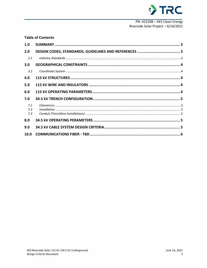
REVISION INDEX
REVISION
NUMBER
DESCRIPTION DATE BY
A IFR - Issued for 30% Client
Review
3/1/2021 TRC
B IFR – Issued for 60%
Client Review
4/15/2021 TRC
C IFP – Issued for Permit 6/14/2021 TRC
PN: 422208 – AES Clean Energy
Riverside Solar Project – 6/14/2021
AES Riverside Solar 115 kV /34.5 kV Underground June 14, 2021
Design Criteria Document 2
Table of Contents
1.0 SUMMARY .................................................................................................................. 3
2.0 DESIGN CODES, STANDARDS, GUIDELINES AND REFERENCES ....................................... 3
2.1 Industry Standards ....................................................................................................................................... 3
3.0 GEOGRAPHICAL CONSTRAINTS .................................................................................... 4
3.1 Coordinate System ....................................................................................................................................... 4
4.0 115 kV STRUCTURES .................................................................................................... 4
5.0 115 kV WIRE AND INSULATORS ................................................................................... 4
6.0 115 kV OPERATING PARAMETERS ................................................................................ 4
7.0 34.5 kV TRENCH CONFIGURATION ............................................................................... 5
7.1 Clearances .................................................................................................................................................... 5 7.2 Installation ................................................................................................................................................... 5 7.3 Conduit (Trenchless Installations) ................................................................................................................ 5
8.0 34.5 kV OPERATING PERAMETERS ............................................................................... 5
9.0 34.5 kV CABLE SYSTEM DESIGN CRITERIA ..................................................................... 5
10.0 COMMUNICATIONS FIBER - TBD .................................................................................. 6
PN: 422208 – AES Clean Energy
Riverside Solar Project – 6/14/2021
AES Riverside Solar 115 kV /34.5 kV Underground June 14, 2021
Design Criteria Document 3
1.0 SUMMARY
Riverside Solar is a proposed 100 MW solar and 20 MW battery energy storage facility in the
towns of Lyme and Brownville, NY. This document summarizes the design criteria for the 115
kV Transmission Interconnection, as well as the 34.5 kV collector cable system from the solar
inverters to the collector substation.
This document defines criteria for:
• 115 kV Structures
• 115 kV Wire and Insulators
• 115 kV Operating parameters
• 34.5 kV Trench layout
• 34.5 kV Cable operating parameters
• 34.5 kV Cable
2.0 DESIGN CODES, STANDARDS, GUIDELINES AND REFERENCES
A summary of codes, industry standards, and guides to be referenced, as needed, are listed
below. Application of these codes, standards, guidelines, and references have been considered
at the discretion of the responsible engineer based upon Federal and State requirements, and
as per the specific needs and objectives of the project.
2.1 Industry Standards
• ANSI C2, National Electric Safety Code (NESC), 2017
• ANSI Z535.2011 Product Safety Signs and Labels
• ACI 318: Building Code Requirements for Structural Concrete
• ASCE 48: Design of Steel Transmission Pole Structures
• ASCE 72: Design of Steel Transmission Pole Structures
• ASCE 74: Guidelines for Electrical Transmission Line Structural Loading
• ASCE 91: Design of Guyed Electrical Transmission Structures
• ICEA S-93-639 5-46 kV Shielded Power Cable for Use in the Transmission and Distribution of
Electric Energy
• IEC 60287, Electric cables – Calculation of the current rating – Part 2-1: Thermal resistance
– Calculation of thermal resistance.
• IEC 60383-2: Ceramic or Glass Insulators Units for AC Systems - Part 1
• IEEE 524: Guide to Installation of Overhead Transmission Line Conductors
• IEEE 738: Standard for Calculating the Current-Temperature of Bare Overhead Conductors
• IEEE 48, IEEE Standard for Test Procedures and Requirements for Alternating-Current Cable
Terminations Used on Shielded Cables Having Laminated Insulation Rated 2.5 kV through
765 kV or Extruded Insulation Rated 2.5 kV through 500 k, 2009.
• IEEE 404, IEEE Standard for Extruded and Laminated Dielectric Shielded Cable Joints Rated
2.5 kV to 500 kV, 2012.
• RUS BULLETIN 1724E-200 Design Manual for High Voltage Transmission Lines

PN: 422208 – AES Clean Energy
Riverside Solar Project – 6/14/2021
AES Riverside Solar 115 kV /34.5 kV Underground June 14, 2021
Design Criteria Document 4
• RUS BULLETIN 1728F-806 Specifications and Drawings for Underground Electric Distribution
• UL 1072 Standard for Medium-Voltage Power Cables
Other recognized standards have been be used where appropriate to serve as guidelines for the
design, when not in conflict with the above listed standards.
It is assumed that 115 kV transmission interconnection will be designed to National Grid
standards.
3.0 GEOGRAPHICAL CONSTRAINTS
3.1 Coordinate System
NAD83 NY central, US foot coordinate system
4.0 115 kV STRUCTURES
Type Three Pole Steel Deadend (H0.ST.DT.00)
Foundation Direct embedded pole with guys
Augured hole with Corrugated Metal Pipe
(CMP)
5.0 115 kV WIRE AND INSULATORS
Power Conductor Non-Specular 795 kcmil 26/7 ACSR “Drake”
Shield Wire N/A
Insulators Porcelain Disc - Grey
In-Line Disconnects Cleaveland Price C02B007G02
6.0 115 kV OPERATING PARAMETERS
Frequency 60 Hz
Nominal Phase to Phase Operating Voltage
Max Phase to Phase Operating Voltage
115 kV
121 kV
Maximum Steady State Ampacity 560 Amps
Emergency Ampacity N/A
PN: 422208 – AES Clean Energy
Riverside Solar Project – 6/14/2021
AES Riverside Solar 115 kV /34.5 kV Underground June 14, 2021
Design Criteria Document 5
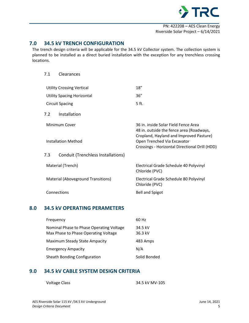
7.0 34.5 kV TRENCH CONFIGURATION The trench design criteria will be applicable for the 34.5 kV Collector system. The collection system is
planned to be installed as a direct buried installation with the exception for any trenchless crossing
locations.
7.1 Clearances
Utility Crossing Vertical 18”
Utility Spacing Horizontal 36”
Circuit Spacing 5 ft.
7.2 Installation
Minimum Cover 36 in. inside Solar Field Fence Area
48 in. outside the fence area (Roadways,
Cropland, Hayland and Improved Pasture)
Installation Method Open Trenched Via Excavator
Crossings - Horizontal Directional Drill (HDD)
7.3 Conduit (Trenchless Installations)
Material (Trench) Electrical Grade Schedule 40 Polyvinyl
Chloride (PVC)
Material (Aboveground Transitions) Electrical Grade Schedule 80 Polyvinyl
Chloride (PVC)
Connections Bell and Spigot
8.0 34.5 kV OPERATING PERAMETERS
Frequency 60 Hz
Nominal Phase to Phase Operating Voltage
Max Phase to Phase Operating Voltage
34.5 kV
36.3 kV
Maximum Steady State Ampacity 483 Amps
Emergency Ampacity N/A
Sheath Bonding Configuration Solid Bonded
9.0 34.5 kV CABLE SYSTEM DESIGN CRITERIA
Voltage Class 34.5 kV MV-105

PN: 422208 – AES Clean Energy
Riverside Solar Project – 6/14/2021
AES Riverside Solar 115 kV /34.5 kV Underground June 14, 2021
Design Criteria Document 6
Conductor Size 1/0 AWG AL, 2/0 AWG AL, 250 MCM AL, 4/0
AWG AL, 350 MCM AL, 500 MCM AL, 750
MCM AL
Insulation Ethylene-Propylene Rubber (EPR) or Tree
Resistant Cross-Linked Polyethylene (TR-
XLPE)
Insulation Level 100%
10.0 COMMUNICATIONS FIBER
Type 24 Strand Single Mode Cable
Qty. Single Cable per Circuit
Conduit 1.25” HDPE