appendix 8-b drainage impact assessmentmarine.gov.scot/datafiles/lot/ahep/volume 3/technical...
TRANSCRIPT

Volume 3:Technical
Appendices
ABERDEEN HARBOUR EXPANSION PROJECT
November 2015
APPENDIX 8-B DRAINAGE IMPACT ASSESSMENT


FUGRO EMU LIMITED
ABERDEEN HARBOUR EXPANSION PROJECT
DRAINAGE IMPACT ASSESSMENT
Report Reference. P1974D_RN3870_Rev2
Issued 20 October 2015
Intertek Exchange House
Liphook Hants GU30 7DW
United Kingdom
Tel: +44 (0) 1428 727800 Fax: +44 (0) 1428 727122
E-mail: [email protected]
Web Site: www.intertek.com

DOCUMENT RELEASE FORM
Title: ABERDEEN HARBOUR EXPANSION PROJECT
DRAINAGE IMPACT ASSESSMENT
Client: FUGRO EMU LIMITED
Report Reference: P1974D_RN3870_REV2
Date of Issue: 20 October 2015
Hard Copy Digital
Distribution: FUGRO EMU LIMITED No: n/a PDF
Intertek Energy & Water Consultancy Services No: n/a PDF
Prepared By: Paul Garrad
Project Manager: Authoriser:
Alasdair Fraser Chris Mooij
Rev No Date Reason Author Checker Authoriser
Rev 0 14/08/15 Original PG AF CPM
Rev 1 10/09/15 Client feedback AF AF pp CPM
Rev 2 20/10/15 Client feedback AS CPM CPM
COPY NUMBER: (applies to hard copies only)
Intertek Energy & Water Consultancy Services is the trading name of Metoc Ltd, a member of the Intertek group of companies

FUGRO EMU LIMITED ABERDEEN HARBOUR EXPANSION PROJECT
REPORT REFERENCE: P1974D_RN3870_REV2 20/10/2015
SUMMARY Fugro EMU Limited (Fugro) is carrying out environmental investigations on behalf of
Aberdeen Harbour Board (AHB) for the proposed development of an additional harbour site
at Nigg Bay, Aberdeen. These investigations have required that a Drainage Impact
Assessment (DIA) was carried out for the development to assess the impact that the
construction of the development could have on local drainage behaviour and infrastructure.
Intertek Energy & Water Consultancy Services (Intertek) was engaged by Fugro to carry out
this work and provide information to be used in the Environmental Statement for the
proposed development.
Nigg Bay is located 2 km to the south west of Aberdeen City Centre and is an east facing bay
bordering onto the North Sea. It has a sandy foreshore and areas of marram grass and sand
dunes behind. The ground level rises from 0 m Above Ordnance Datum (AOD) at the
shoreline to 50 m AOD on the headlands to the north and south. The Coast Road/Greyhope
Road around the bay rises above the 10 m contour but, in the centre of the bay, where it
crosses the East Tullos Burn, is around 4 m AOD. The East Tullos Burn is the principal
drainage route for the catchment area to the west of the bay.
The bay is largely undeveloped at present, with the exception of Nigg Wastewater Treatment
Works (WwTW) at the southern end of the bay. The outline plans for the development are to
provide three new quay facilities in a south facing U shape with an offshore breakwater.
The deck height of the quays is to be constructed at an elevated level and will cover a
surface area of approximately 20,000 m2. The resultant increase in impermeable area will
cause a significant increase in runoff rate from the development. However, following
considerations of the planning requirements and the applicability of Sustainable Urban
Drainage Systems (SUDS), it is considered appropriate for the surface water runoff to
discharge to sea without the use of SUDS. Oil/petrol interceptors must be included in the
design of the drainage network to prevent contamination of the sea during rainfall or pollutant
spill conditions. Consideration of the drainage system’s operation as intended and during
failure conditions should be incorporated in the design to minimise the risk to the
environment.
Rainwater harvesting should be considered for the reuse of grey water to reduce runoff and
to provide a potential resource to minimise potable water use on the site.
Foul drainage is likely to be connected to the main trunk sewer just upstream of Nigg WwTW.
The invert levels of the pipes indicate that this could be done with the minimum of additional

FUGRO EMU LIMITED ABERDEEN HARBOUR EXPANSION PROJECT
REPORT REFERENCE: P1974D_RN3870_REV2 20/10/2015
infrastructure. However, care will need to be taken to ensure that two outfall pipes that run
through the site continue to operate as intended, both during construction and operational
phases of the harbour development.
The work carried out during this DIA has allowed the following conclusions to be made:
The impact of foul drainage on the wider sewerage network is likely to be negligible,
given the location of the proposed site adjacent to Nigg WwTW.
A connection to the combined sewerage system is likely to be straightforward with the
minimum of additional infrastructure.
Existing sewerage assets will need to be protected and maintained as per their current
operation during the construction and operations of the proposed harbour
development. The two assets of key concern are the WwTW’s Long Sea Outfall (LSO)
and a Combined Sewer Overflow (CSO) outfall on the north coast of the bay.
Calculations have determined a significant increase in runoff as a result of the
development. However, the design of the harbour, and the fact that it will discharge to
sea, means that drainage impacts are negligible.
SUDS are unlikely to be required, given the discharge to sea. However, the receiving
environment should be protected from pollution spills and surface runoff through the
installation of petrol/oil interceptors and control valves that prevent contaminated runoff
or spills reaching the sea. Consideration of flow routes during normal operation and
partial failure should be considered in their design.
Rainwater harvesting should be considered in the final drainage design to feed any
grey water needs on the site.
FUGRO EMU LIMITED ABERDEEN HARBOUR EXPANSION PROJECT
REPORT REFERENCE: P1974D_RN3870_REV2 20/10/2015
CONTENTS 1 INTRODUCTION ................................................................................................. 1
1.1 EXISTING SITE ....................................................................................................... 1
1.2 PROPOSED DEVELOPMENT ..................................................................................... 5
2 DRAINAGE IMPACT .......................................................................................... 7
2.1 WASTEWATER DRAINAGE ....................................................................................... 7
2.2 SURFACE WATER DRAINAGE .................................................................................. 8
2.3 DEVELOPED SITE RUNOFF WITHOUT SUDS ............................................................. 9
2.4 SUSTAINABLE URBAN DRAINAGE SYSTEMS ............................................................ 10
2.5 OUTLINE DRAINAGE STRATEGY ............................................................................. 11
3 CONCLUSIONS ................................................................................................ 12
4 REFERENCES .................................................................................................. 13
TABLES TABLE 1-1: SURFACE AREA OF PROPOSED STRUCTURES ........................................................ 5
TABLE 1-2: HEIGHT OF STRUCTURES TO CHART DATUM AND ORDNANCE DATUM...................... 6
TABLE 2-1: EXISTING SITE PEAK FLOWS AND VOLUMES ........................................................... 9
TABLE 2-2: DEVELOPED SITE PEAK FLOWS AND VOLUMES WITHOUT SUDS ............................. 9
TABLE 2-3: POTENTIAL SUDS OPTIONS ................................................................................ 11
FIGURES FIGURE 1-1: LOCATION MAP ................................................................................................... 2
FIGURE 1-2: PROPOSED OPTION 6 LAYOUT OF THE ABERDEEN HARBOUR EXPANSION AT NIGG BAY ................................................................................................................................. 3
FIGURE 1-3: AERIAL PHOTOGRAPH ......................................................................................... 4
FIGURE 1-4: SITE PHOTOGRAPH ............................................................................................. 4

FUGRO EMU LIMITED ABERDEEN HARBOUR EXPANSION PROJECT
REPORT REFERENCE: P1974D_RN3870_REV2 20/10/2015
ABBREVIATIONS ACD Above Chart Datum
AOD Above Ordnance Datum
AHB Aberdeen Harbour Board
CSO Combined Sewer Overflow
DIA Drainage Impact Assessment
FEH Flood Estimation Handbook
FRA Flood Risk Assessment
LSO Long Sea Outfall
SEPA Scottish Environment Protection Agency
SUDS Sustainable Urban Drainage Systems
WwTW Wastewater Treatment Works

FUGRO EMU LIMITED ABERDEEN HARBOUR EXPANSION PROJECT
REPORT REFERENCE: P1974D_RN3870_REV2 1 20/10/2015
1 INTRODUCTION
Fugro EMU Limited (Fugro) is carrying out environmental investigations on behalf of Aberdeen Harbour Board (AHB) for the proposed development of an additional harbour site at Nigg Bay, Aberdeen. These investigations have required that a Drainage Impact Assessment (DIA) was carried out for the development to assess the impact that the construction of the development could have on local drainage behaviour and infrastructure. Intertek Energy & Water Consultancy Services (Intertek) was engaged by Fugro to carry out this work and provide information to be used in the Environmental Statement for the proposed development.
1.1 EXISTING SITE
The proposed development site of Nigg Bay is located 2 km to the south west of Aberdeen City Centre (Figure 1-1). Nigg Bay is an east facing bay bordering onto the North Sea (Figure 1-2), with a sandy foreshore and areas of marram grass and sand dunes behind as shown on an aerial photograph (Figure 1-3) and a site photograph (Figure 1-4).
The ground level rises from 0.0 m Above Ordnance Datum (AOD) at the shoreline to 50 m AOD on the headlands to the north and south (Figure 1-1). The Coast Road/Greyhope Road around the bay rises above the 10 m contour but, in the centre of the bay where it crosses the East Tullos Burn, is around 4 m AOD.

.ABERDEEN HARBOUR EXPANSION
PROJECTFigure 1-1: Geographic overview of the
area of interest
Created ByReviewed By
Emma Langley
Ian Charlton
Monday, September 7, 2015 09:48:11
British_National_Grid
D_OSGB_1936
OSOD, SNH, JNCC, SEPA
J:\P1974\Mxd\Method_Statement\Geographical_Overview.mxd
Airy_1830
DateProjection
DatumData Source
File Reference
Spheroid
NOTE: Not to be used for Navigation
Contains Ordnance Survey data © Crown copyright and database right 2013. Copyright Scottish Natural Heritage) Contains Ordnance Survey data © Crown copyright and database right (2014)) © SEPA 2014.
Approved By Kevin McGovern
Ythan Estuary and Sands of Forvie draft Special Protection Area
River Dee SpecialArea of Conservation
Nigg Bay Site of SpecialScientific Interest
Cove Site of SpecialScientific Interest
Aberdeen BallroomBathing Water
392000
392000
394000
394000
396000
396000
398000
398000
400000
400000
8020
00
8020
00
8040
00
8040
00
8060
00
8060
00
8080
00
8080
00
LegendAberdeen Harbour Expansion Project areaExisting Aberdeen Harbour Area
Special Area of ConservationSite of Special Scientific InterestDraft Special Protection Area
_̂ Bathing Water Monitoring LocationAberdeen Ballroom Bathing Water
0 0.4 0.8 1.2 1.60.2km
.
© Metoc Ltd, 2015.All rights reserved.

.ABERDEEN HARBOUR EXPANSION
PROJECT
Figure 1-2: Extraction Locations
Created ByReviewed By
Ian Charlton
Emma Langley
Thursday, September 10, 2015 17:26:32
British_National_Grid
D_OSGB_1936
OSOD, FUGRO
J:\P1974\Mxd\WQ_Extraction_Locations_v4.mxd
Airy_1830
DateProjection
DatumData Source
File Reference
Spheroid
NOTE: Not to be used for Navigation
Contains Ordnance Survey data © Crown copyright and database right 2013
Approved By Paul Taylor
#7
#7
#7
#7
_̂
_̂_̂
_̂
_̂
_̂_̂
_̂
_̂
EastT ullosBurn
Ness T ip Burn
UFPoutfall
St Fittick ’sField CSO
1
23
4
5
67
Nigg BaySSSI
SSSI 2
SSSI 1
396000
396000
396500
396500
397000
397000
397500
397500
398000
398000
804000
804000
804500
804500
805000
805000
805500
805500
Legend_̂ Model extraction locations
#7 Discharge LocationAberdeen Harbour Expansion ProjectSuspended Deck StructureSite of Special Scientific Interest
0 100 200 300 400m
.
© Metoc Ltd, 2015.All rights reserved.

FUGRO EMU LIMITED ABERDEEN HARBOUR EXPANSION PROJECT
REPORT REFERENCE: P1974D_RN3870_REV2 4 20/10/2015
Figure 1-3: Aerial Photograph
Imagery ©2015 Infoterra Ltd & Bluesky, The GeoInformation Group, Data S10, NOAA, U.S. Navy, NGA, GEBCO, Map data ©2015
Figure 1-4: Site Photograph

FUGRO EMU LIMITED ABERDEEN HARBOUR EXPANSION PROJECT
REPORT REFERENCE: P1974D_RN3870_REV2 5 20/10/2015
1.2 PROPOSED DEVELOPMENT
Aberdeen Harbour Board has proposed the design and construction of a new harbour facility at Nigg Bay, immediately south of the existing harbour. The purpose of the new facility is to complement and expand the capabilities of the existing harbour, accommodate larger vessels, retain existing custom, and attract increased numbers of vessels and vessel types to Aberdeen.
The new harbour development shall include but is not limited to:
Dredging the existing bay to accommodate vessels up to 9 m draft with additional dredge depth of 10.5 m to the east quay and entrance channel;
Construction of new North and South breakwaters to form the harbour;
Provision of approximately 1,500 m of new quays and associated support infrastructure. The quay will be constructed with solid quay wall construction and suspended decks over open revetment;
Construction of areas for development by others to facilitate the provision of fuel, bulk commodities and potable water;
Land reclamation principally through using materials recovered from dredging operations and local sources, where possible;
Provision of ancillary accommodation for the facility;
Off-site highway works to the extent necessary to access the facility and to satisfy statutory obligations; and
Diversions and enabling works necessary to permit the development.
The outline plans are to provide three new quay facilities in a south facing U shape with an offshore breakwater (Figure 1-2). The deck height of the west, north and east quays and the south-east breakwater will be at 6.7 m Above Chart Datum (ACD). The new quay areas will cover a surface area of approximately 20,000 m2 (Table 1-1).
Table 1-1: Surface Area of Proposed Structures
Items Length (m) Width (m) Area (m2) North Quay 400 15 6,000 West Quay 300 10 3,000 East Quay 400 15 6,000 Breakwater 500 10 5,000
Total 20,000
The breakwaters will be constructed of Coreloc which will angle up from the sea bed in the dredged approach channel, or the natural bed level elsewhere, to the top of the structure at +12 m ACD (Table 1-2). The suspended deck structure on the West Quay and part of North Quay will be an angled revetment and rock armoured, sloping up from the dredged harbour depth of -10 m ACD to just below the deck level at +6.7 m ACD. The deck itself will sit on top of a series of piles. The south east Pier, East Quay and the east part of North Quay will all have a vertical hard face.

FUGRO EMU LIMITED ABERDEEN HARBOUR EXPANSION PROJECT
REPORT REFERENCE: P1974D_RN3870_REV2 6 20/10/2015
Table 1-2: Height of Structures to Chart Datum and Ordnance Datum
Items Height (m ACD) Height (m AOD) (CD = OD -2.25 m)
Quay Side 6.7 4.45 Breakwater 12.0 9.75 Harbour Depth -10.0 -12.25 Approach Channel Depth -11.5 -13.75
The new harbour would be dredged to -9 m ACD for the main basin and -10.5 m ACD for the approach channel and East Quay berth.

FUGRO EMU LIMITED ABERDEEN HARBOUR EXPANSION PROJECT
REPORT REFERENCE: P1974D_RN3870_REV2 7 20/10/2015
2 DRAINAGE IMPACT
Planning Policy and Scottish Water Policy require that a DIA is undertaken to ensure that surface drainage issues have been adequately planned and that sewerage and drainage infrastructure will be able to deal with additional flows generated by the development.
2.1 WASTEWATER DRAINAGE
Although surface water flows can be discharged to sea, foul wastewater flows are required to be kept separate from storm flows and it is recommended that these are discharged to the public sewer.
The impact of additional foul flow on the sewerage network is often assessed using sewer network modelling. This analysis is carried out to identify the impact that conveying additional flows will have on the network so that the overall performance of the network, in terms of flooding and Combined Sewer Overflow (CSO) discharges, is not detrimentally affected. However, in the case of the proposed development at Nigg Bay, the site is located immediately adjacent to the Nigg Wastewater Treatment Works (WwTW). It is therefore highly unlikely that a foul connection at this point would have any detrimental effects on network performance. The main trunk sewer to the WwTW runs along the western edge of the proposed development making connection likely with the minimum of additional infrastructure. The pipe level at this point is not recorded in Scottish Water’s GIS records, but an interpolation from adjacent pipe levels suggests an invert level of approximately 0.3 m AOD. Given the intention to construct the ground level of the harbour at an elevated level, it is not anticipated that pumping facilities will be required.
The key concern regarding the existing infrastructure will be the effects to outfalls from the sewerage network. The review of the GIS records revealed that there are two outfalls that would be likely to be impacted by the development (see Figure 1-1). The first is the main Long Sea Outfall (LSO) from the Nigg WwTW. This currently extends out from the southern end of the bay in an easterly direction. Care would be required to either avoid this outfall in the design, or ensure that mitigation methods are taken during construction to allow discharge to occur at its current discharge location, and that post construction discharge performance is not affected. The second outfall is a 2,250 mm diameter brick overflow outfall that runs along the northern banks of the bay, discharging at the headland. This appears to still be in use and its depth is likely to be shallow enough to be affected by the construction of the harbour. This pipe would be required to be retained in the final design, with access accommodated. Further discussions on these outfalls will be required with Scottish Water and the Nigg WwTW operator (Kelda Water).
A Pre-Development Enquiry Application has been submitted to Scottish Water to initiate the process of gaining a connection to the public sewer.

FUGRO EMU LIMITED ABERDEEN HARBOUR EXPANSION PROJECT
REPORT REFERENCE: P1974D_RN3870_REV2 8 20/10/2015
2.2 SURFACE WATER DRAINAGE
Scottish Planning Policyi requires that any surface water runoff from a new development should be treated by a sustainable drainage system (SUDS) before it is discharged into the water environment, except where the discharge will be into coastal waters. The aim of SUDS is to mimic natural drainage, encourage infiltration and attenuate and reduce the risk of flooding, both on and off the site. A degree of water quality treatment is also performed by SUDS. Planning permission should not be granted unless the proposed arrangements for surface water drainage are adequate, and appropriate long term maintenance arrangements are in place.
The Scottish Environment Protection Agency’s (SEPA) guidance also encourages surface water runoff from all developments to be treated by SUDS. This requires that a DIA or Flood Risk Assessment (FRA) should include a preliminary assessment of the surface water drainage requirements including:
A comparison of pre- and post-development surface-water runoff.
The means of any treatment needed.
Attenuation requirements.
Indicative SUDS proposals if required, identifying suitable outfall locations.
Approval in principle will be requested from SEPA and Aberdeen City Council for the drainage proposals, once finalised. The level of SUDS required is dependent on the nature and size of development, and the environmental risk posed by the development which is principally determined by the available dilution of the receiving water body.
2.2.1 Existing Site Runoff
The CIRIA guidance on SUDS (CIRIA C697) recommends the use of the Institute of Hydrology’s method for determining runoff from small catchmentsii (IH124) for Greenfield runoff calculations on sites less than 50 ha. However, this site area is small (1.44 ha), far below the lower limit of the IH124 method (110 ha) and as the developed site will be urban and it does not contain a watercourse, IH124 is not considered valid. A recent Environment Agency research and development report (SC090031) recommended that IH124 should not be used for site runoff calculations and this is included in the latest Flood Estimation Handbook (FEH) Guidelines. Peak flows and volumes are therefore based on the Wallingford or Modified Rational Methodiii based on the drainage area, the runoff characteristics (percentage runoff) and the rainfall intensity for a range of storms durations and return periods.
The existing site of 20,000m2 (Table 1-1) is assumed to drain naturally at the FEHiv percentage runoff rate of 18.1%. Rainfall totals are given by the FEH at the nearest 1 km grid point to the site (NJ 9640 0480) and as these calculations are for the present day this rainfall is not increased to account for climate change. This gives a 100 year 30 minute storm peak flow of 44 l/s and storm volume of 80 m3 whilst the 100 year 6 hour storm peak flow is 10 l/s and volume of 223 m3 (Table 2-1).

FUGRO EMU LIMITED ABERDEEN HARBOUR EXPANSION PROJECT
REPORT REFERENCE: P1974D_RN3870_REV2 9 20/10/2015
Table 2-1: Existing Site Peak Flows and Volumes
Return 30 min 1 hour 3 hour 6 hour
Period (yrs)
Peak Flow (l/s)
Volume (m3)
Peak Flow (l/s)
Volume (m3)
Peak Flow (l/s)
Volume (m3)
Peak Flow (l/s)
Volume (m3)
2 15.0 27.0 10.3 37.1 5.7 61.5 3.9 84.5 5 20.8 37.5 14.2 51.0 7.7 83.2 5.3 113.2 10 25.2 45.4 17.1 61.4 9.2 99.3 6.2 134.4 25 31.8 57.2 21.4 76.9 11.4 122.9 7.7 165.3 50 37.6 67.7 25.2 90.5 13.3 143.6 8.9 192.2 100 44.4 79.9 29.6 106.3 15.5 167.4 10.3 222.9
2.3 DEVELOPED SITE RUNOFF WITHOUT SUDS
The developed site will include the same 20,000 m2 area covered by impermeable buildings, roads and other surfaces with an assumed urban percentage runoff of 75%. SEPA also requires the impact of climate change to be considered and the latest guidance suggests a 20% increase in rainfall by 2060 and 30% by 2110. Assuming this commercial development has a design life of 100 years, the rainfall totals are increased by 30%. The peak flows from the developed site without SUDS (Table 2-2) suggests the 100 year 30 minute storm will provide a peak flow of 239 l/s and a volume of 429 m3, whilst the 100 year 6 hour storm peak flow of 56 l/s and volume of 1198 m3.
Table 2-2: Developed Site Peak Flows and Volumes without SUDS
Return 30 min 1 hour 3 hour 6 hour
Period (yrs)
Peak Flow (l/s)
Volume (m3)
Peak Flow (l/s)
Volume (m3)
Peak Flow (l/s)
Volume (m3)
Peak Flow (l/s)
Volume (m3)
2 80.7 145.2 55.5 199.6 30.6 330.4 21.0 454.2 5 112.0 201.4 76.2 274.1 41.4 447.1 28.2 608.6 10 135.6 243.8 91.8 330.1 49.4 533.5 33.5 722.3
25 170.9 307.3 114.9 413.2 61.2 660.7 41.2 888.4
50 202.2 363.7 135.3 486.6 71.5 771.9 47.9 1032.9 100 238.7 429.3 158.9 571.6 83.4 899.9 55.5 1198.2
This 430% increase in peak flows and volumes above the existing rate is due to the 30% increase in rainfall from climate change and the larger impermeable area with its higher percentage runoff.
The use of SUDS to reduce the developed site peak flow rates and volumes to the existing rate is considered in Section 2.4 so that the impact on the flooding potential for other adjacent sites is not increased.
FUGRO EMU LIMITED ABERDEEN HARBOUR EXPANSION PROJECT
REPORT REFERENCE: P1974D_RN3870_REV2 10 20/10/2015
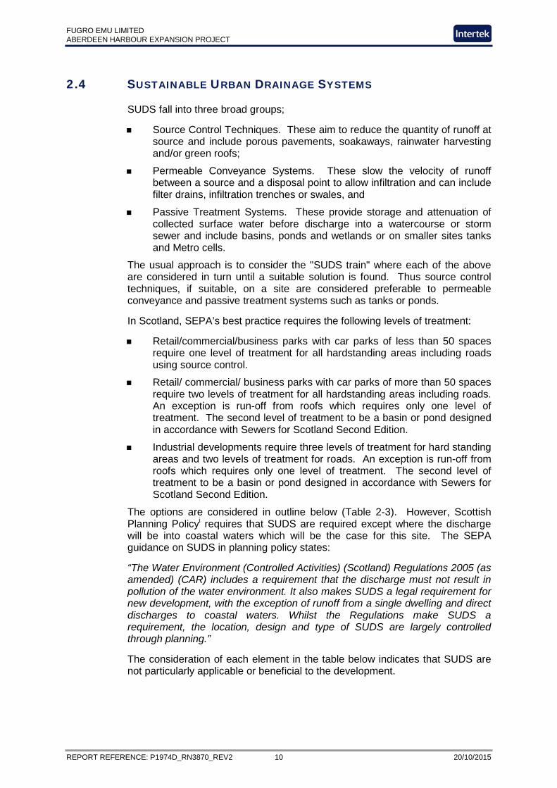
2.4 SUSTAINABLE URBAN DRAINAGE SYSTEMS
SUDS fall into three broad groups;
Source Control Techniques. These aim to reduce the quantity of runoff at source and include porous pavements, soakaways, rainwater harvesting and/or green roofs;
Permeable Conveyance Systems. These slow the velocity of runoff between a source and a disposal point to allow infiltration and can include filter drains, infiltration trenches or swales, and
Passive Treatment Systems. These provide storage and attenuation of collected surface water before discharge into a watercourse or storm sewer and include basins, ponds and wetlands or on smaller sites tanks and Metro cells.
The usual approach is to consider the "SUDS train" where each of the above are considered in turn until a suitable solution is found. Thus source control techniques, if suitable, on a site are considered preferable to permeable conveyance and passive treatment systems such as tanks or ponds.
In Scotland, SEPA’s best practice requires the following levels of treatment:
Retail/commercial/business parks with car parks of less than 50 spaces require one level of treatment for all hardstanding areas including roads using source control.
Retail/ commercial/ business parks with car parks of more than 50 spaces require two levels of treatment for all hardstanding areas including roads. An exception is run-off from roofs which requires only one level of treatment. The second level of treatment to be a basin or pond designed in accordance with Sewers for Scotland Second Edition.
Industrial developments require three levels of treatment for hard standing areas and two levels of treatment for roads. An exception is run-off from roofs which requires only one level of treatment. The second level of treatment to be a basin or pond designed in accordance with Sewers for Scotland Second Edition.
The options are considered in outline below (Table 2-3). However, Scottish Planning Policyi requires that SUDS are required except where the discharge will be into coastal waters which will be the case for this site. The SEPA guidance on SUDS in planning policy states:
“The Water Environment (Controlled Activities) (Scotland) Regulations 2005 (as amended) (CAR) includes a requirement that the discharge must not result in pollution of the water environment. It also makes SUDS a legal requirement for new development, with the exception of runoff from a single dwelling and direct discharges to coastal waters. Whilst the Regulations make SUDS a requirement, the location, design and type of SUDS are largely controlled through planning.”
The consideration of each element in the table below indicates that SUDS are not particularly applicable or beneficial to the development.

FUGRO EMU LIMITED ABERDEEN HARBOUR EXPANSION PROJECT
REPORT REFERENCE: P1974D_RN3870_REV2 11 20/10/2015
Table 2-3: Potential SUDS options
2.5 OUTLINE DRAINAGE STRATEGY
As the site lies adjacent to the sea there is no requirement or benefit in using SUDS to control peak flow and the volume of runoff. The main issue is water quality and ensuring pollution events such as spillage on the quays do not occur or can be controlled. The installed drainage network should therefore include petrol interceptors and control valves to prevent any spillage of contaminants from entering the coastal environment.
As part of the development proposals a new drainage system with such controls will be designed for the site and the final drainage scheme will be considered at the detailed design stage. The flow routes under normal conditions, and in the event of a system failure or the storage facility being full, would also be considered as part of these detailed designs. However, as the ground floor slab and all access and services entrances will be raised above the local ground level, then flooding of the site will not occur in the event of local drainage system failure, whether by extreme rainfall or a lack of maintenance.
Rainwater harvesting should be considered for providing grey water for operational uses on the site.
Type of SUDS Method Comment Applicability to this Site
Source Control Techniques
Soakaways Although geology is permeable the groundwater levels will be close to normal sea level and this may restrict vertical drainage.
Not possible due to groundwater levels. Not required as discharge is to sea.
Permeable Pavements Due to heavy vehicle movements on the site these are unlikely to be suitable as these could damage the pavement infrastructure.
Not possible due to heavy traffic movement. Not required as discharge is to sea.
Rainwater harvesting Only suitable for roofed buildings and if there is a demand for water.
Only suitable for roofed buildings. Not required as discharge is to sea.
Green Roof Only suitable for roofed buildings. Only suitable for roofed buildings. Not required as discharge is to sea.
Permeable Conveyance
Swales No available space for a length of swale and not a practical option.
Not practicable and not required as discharge is to sea.
Infiltration trenches With high groundwater levels these are not suitable and not practical for the proposed development.
Not possible due to groundwater levels. Not required as discharge is to sea.
Passive treatment
Tanks Underground tanks could be considered but there is no benefit if runoff is released to the sea.
No benefit. Not required as discharge is to sea.
Storm Cells As above As above Oversized drainage network As above As above Ponds Unsuitable on this site As above

FUGRO EMU LIMITED ABERDEEN HARBOUR EXPANSION PROJECT
REPORT REFERENCE: P1974D_RN3870_REV2 12 20/10/2015
3 CONCLUSIONS
The potential impacts of the Aberdeen Harbour Expansion Project on the drainage of the area and local drainage infrastructure have been considered in this investigation. From this work, the following conclusions have been reached:
The impact of foul drainage on the wider sewerage network is likely to be negligible given the location of the proposed site adjacent to Nigg WwTW.
A connection to the combined sewerage system is likely to be straightforward with the minimum of additional infrastructure.
Existing sewerage assets will need to be protected and maintained as per their current operation during the construction and operations of the proposed harbour development. The two assets of key concern are the WwTW’s LSO and a CSO outfall on the north coast of the bay.
Calculations have determined a significant increase in runoff as a result of the development. However, the design of the harbour and the fact that it will discharge to sea, means that drainage impacts are negligible.
SUDS are unlikely to be required given the discharge to sea. However, the receiving environment should be protected from pollution spills and surface runoff through the installation of petrol/oil interceptors and control valves that prevent contaminated runoff or spills reaching the sea. Consideration of flow routes during normal operation and partial failure should be considered in their design.
Rainwater harvesting should be considered in the final drainage design to feed any grey water needs on the site.

FUGRO EMU LIMITED ABERDEEN HARBOUR EXPANSION PROJECT
REPORT REFERENCE: P1974D_RN3870_REV2 13 20/10/2015
4 REFERENCES
i Scottish Environment Protection Agency. Land Use Planning System SEPA Guidance Note 2. Report identifier: LUPS-GU2. Version 8. 31/08/2010 ii Institute of Hydrology. Report No. 124. Flood Estimation for Small Catchments. June 1994. iii HR Wallingford (1981). Wallingford Procedure for design and analysis of urban storm drainage ivCentre for Ecology and Hydrology 1999. Flood Estimation Handbook