appendix a advanced technologies and systems
TRANSCRIPT

93
Appendix A
ADVANCED TECHNOLOGIES AND SYSTEMS
Chapters Three and Four presented alternative concepts for finding,recognizing, and defeating elusive maneuver or mobile missileforces. This appendix discusses the technological advances that willbe necessary before these concepts can be implemented and de-scribes the current state of the art in deployed systems, ongoing R&Defforts, and major technical challenges to be overcome.
Starting from the ground and moving up, we discuss unattendedground sensors (UGS); automatic target recognition (ATR); micro,small, and large unmanned aerial vehicles (UAVs); advanced radars;hyperspectral image processing; and hypersonic weapons.
UNATTENDED GROUND SENSORS
In principle, unattended ground sensors are simpler and more af-fordable than most of the other sensors and sensor platforms of in-terest to the U.S. Air Force (USAF). However, because its focus is onaerospace operations, the USAF’s recent practice has been to useUGS primarily for force protection—for example, the Tactical Au-tomated Security System (TASS), used for air-base perimeter andflight-line protection. (A very notable historical exception was theIgloo White program, which was a major Air Force operation to de-tect enemy activity along the Ho Chi Minh Trail during the VietnamWar.1) Nevertheless, UGS have the potential to be an excellent
______________ 1Eric D. Haider, “Unattended Ground Sensors and Precision Engagement,” NavalPostgraduate School Thesis, Monterey, Calif., December 1998.

94 Aerospace Operations Against Elusive Ground Targets
complement to airborne and spaceborne sensors, especially duringoperations against elusive enemy ground forces operating in the ab-sence of friendly ground forces.
UGS can employ one or more sensing phenomenologies, including,but not limited to, acoustic, seismic, magnetic, electro-optical (EO)imaging, imaging infrared (IIR), pressure, radio-frequency (RF) reso-nance, chemical/biological/nuclear, olfactory, mechanical and in-frared (IR) tripwire, and weather. This book focused primarily on in-tegrated acoustic-seismic UGS, since the technology base is fairlymature and these sensors promise useful capabilities against elusiveenemy ground forces. While more complex to build and employ,imaging UGS also may be useful to aerospace forces and are dis-cussed briefly. In addition, the U.S. government is conducting ex-tensive research on the development of sensors to detect, recognize,and alert friendly forces of chemical and biological weapons attacks,remotely monitor weather patterns, and protect U.S. facilities. Suchapplications are not the focus of this study, and their associatedtechnologies will not be addressed in this appendix.2
UGS have many attributes that make them natural complements toairborne and spaceborne sensors. With the possible exception ofLow Probability of Intercept (LPI) detection alert and status reporttransmissions, most UGS will operate passively (receiving only), re-sulting in low power requirements and reducing their likelihood ofdetection. Modern battery technology enables most designs to oper-ate autonomously for months. UGS affordability should make it fea-sible to deploy vast networks of UGS. Further, while various envi-ronmental conditions will affect the performance of some UGS,generally they would continue to operate in most weather conditionsand would be virtually unaffected by the low cloud ceilings that fre-quently preclude visual and IR-band imaging from medium- andhigh-altitude UAVs, manned aircraft, and satellites. Finally, theirsmall size and fixed locations make UGS difficult to detect visually.
______________ 2For a survey of fielded and developmental UGS systems see Mark Hewish, “SilentSentinels Lie in Wait: Unattended Ground Sensors,” International Defense Review,Vol. 31, Issue 1, January 1, 1998, pp. 48 and following.

Advanced Technologies and Systems 95
In the next several pages, we discuss acoustic UGS, seismic UGS, ad-vantages associated with combined acoustic-seismic UGS, andimaging UGS.
Integrated Acoustic and Seismic UGS
Acoustic and seismic sensors have been used for many years forcivilian and military purposes. Used as unattended sensors, bothphenomenologies are passive, and neither is dependent upon directline of sight to the target being sensed. These attributes contribute tothe sensor’s covertness and low power requirements, and relax re-quirements for sensor placement. In addition, since neither acousticnor seismic sensors need light to operate, they are fully effective atnight, providing a good complement to visual-band imagers.
Acoustic Sensors. Multiple-microphone acoustic UGS can usuallyprovide a rough indication of the bearing to a detected target.However, because UGS are passive devices, data from an individualsensor does not reveal the range. Assuming the target is travelingalong a road, fusing a sensor’s bearing data with the road’s knownlocation can define the approximate target location. Further, if anarray of acoustic UGS is deployed with overlapping coverage, beam-forming3 can enhance the network’s detection, recognition, and lo-cation-estimating performance; triangulation in addition to beam-forming or even instead of it can reveal target location, potentially towithin targeting accuracy. However, if multiple vehicles are present,their combined signals and the timing of the signals arriving at sepa-rated receiver locations will complicate attempts to localize individ-ual targets. Unresolved ambiguities can arise when there is moder-ate to heavy traffic.
Beamforming can help to resolve these ambiguities in the followingway. Once one sensor detects a target, the array would scan a section
______________ 3Beamforming is a process used to improve the signal-to-noise ratio (SNR) and thedirectionality of an array of sensors. Fundamentally, beamforming is accomplished bycollecting the signals from all the array’s elements that are capable of sensing in thedirection of interest, delaying the signals of individual sensors to correct for the vary-ing lengths of time required for the sound to travel from a target source, and summingthe synchronized signals. Greg Allen provides an illustrated tutorial on beamformingtechniques, as well as a short list of related references, at “What Is Beamforming,”http://www.ece.utexas.edu/~allen/Beamforming/, last visited August 22, 2000.

96 Aerospace Operations Against Elusive Ground Targets
of road by picking one point on the road at a time and therebyknowing the distance from the point to each sensor involved. TheUGS would send their signals to a central processor (possibly in oneof the UGS that is acting as the central node at a given time). Theprocessor would consider acoustic data from the microphones of ap-propriate UGS, which are listening in the direction of the point onthe road being considered. The processor would use an algorithm tosynchronize the signals by delaying the employed microphones’ databy the time it would take for the signals to travel from the point inquestion to each sensor. The processor could systematically marchalong the road (or across an area) by repeating this process, sequen-tially considering several discrete points along the road being sur-veyed. One clear drawback to this approach is the need to transmitsignals, which would use battery power and would emit a signal thatthe enemy might be able to detect. Of course, the data for a shortperiod of time need only be transmitted once; for each point consid-ered, the processor can select the appropriate microphone’s dataand timing.
The effective target-detection range of acoustic sensors is typicallyon the order of one kilometer (1 km) when the target is a large mov-ing vehicle; when the target is a pedestrian, it is tens of meters to 100meters (m). The primary range-limiting effect is the sphericalspreading of the sound waves, which causes the signal strength toattenuate in proportion to the square of the range to the target.However, acoustic sensor ranges also vary greatly as a function ofenvironmental conditions, sensor placement within the terrain, andtarget activity. For example, wind distorts and turns sound waves,reducing the sensing range for targets downwind of the sensor andpossibly increasing the sensing range for upwind targets. Similarly,thermal gradients in the atmosphere will refract the sound wavesupward for normal atmospheric thermal gradients, where the airtemperature drops with altitude; they will refract sound wavesdownward for thermal inversions. Thus, at night, when thermal in-versions are fairly common, acoustic ground sensors tend to havegreater effective ranges. While acoustic sensors do not require line ofsight to a target, placing them out of a direct path for sound waves,such as behind a building, in a ravine, or behind a hill, can reducethe signal strength reaching the sensor to such an extent that thesignal-to-noise ratio (SNR) is below the sensor’s operating limits.

Advanced Technologies and Systems 97
Seismic Sensors. Seismic sensors generally have less effective rangethan acoustic sensors. Erteza et al. have demonstrated that the char-acteristics of the ground between the target and the UGS will affectthe geophone’s performance. For example, igneous rocks haveabout ten times the propensity to transmit seismic waves as do un-consolidated sediments.4 However, seismic sensors do not exhibit asmuch range variability with changing weather conditions as doacoustic sensors. As Wellman et al. have pointed out, seismic signa-tures can be used to detect and sometimes to classify and recognizevehicles, especially tracked vehicles.5 However, seismic sensors aregenerally not useful for determining range or bearing to a target, andfor the near term probably should be trusted with the roles of detec-tion and very basic classification.
Integrated Acoustic-Seismic Sensors. The combination of acousticand seismic sensors is a good choice for detecting moving vehicles.Acoustic sensors have a greater range than seismic sensors.Assuming acceptable SNRs for each sensor, the acoustic signal wouldcontain more usable information than would the seismic signal.Therefore, the advantage of integrating acoustic and seismic sensorsis primarily twofold.
First, seismic signals provide confirmation of acoustic detections andrecognitions. Since acoustic and seismic phenomenologies are in-dependent, spurious simultaneous detection alarms are unlikely tooccur coincidentally or as a result of activity by entities that are dis-similar from valid targets. This confirming function would help re-duce acoustic false alarms caused by natural events or by smallcivilian vehicles. In addition, the combination of phenomenologiescomplicates enemy deception efforts. For example, playing back ahigh-quality tape recording of a transporter-erector-launcher (TEL)or tank that contained all relevant portions of the acoustic spectrumwould not produce the corresponding seismic signature.
______________ 4Ireena Erteza et al., Case Study: Unattended Ground Sensor Phenomenology andSignal Processing, Albuquerque, N.M.: Sandia National Laboratories, NationalTechnical Information Service document DE97004441, 1996.5Mark C. Wellman, Nassy Srour, and David B. Hillis, “Feature Extraction and Fusion ofAcoustic and Seismic Sensors for Target Identification,” Proceedings of SPIE, Vol. 3081,Peace and Wartime Applications and Technical Issues for Unattended Ground Sensors,Gerold Yonas, ed., April 22–23, 1997, p. 144.

98 Aerospace Operations Against Elusive Ground Targets
Second, if the acoustic-detection range is severely limited by theUGS’s landing in a crevasse, or being covered by snow, or landingupwind of the target, the seismic geophone may have significantlygreater detection range than the acoustic microphones.
One limitation common to acoustic and seismic UGS is their generalinability to assess the potential for collateral damage in the vicinityof a detected target. Therefore, depending upon the rules of en-gagement (ROE), the nature of the region being monitored, and theconflict, an engagement controller may need to call for EO or IRimagery prior to directing a strike.
Description of an Acoustic-Seismic UGS System. An effective air-deployed acoustic-seismic UGS would consist of microphones, geo-phones, a GPS receiver, a communications system, a clock, a com-puter processor, a hardened ground-penetrating and aerodynamicbody, aerodynamic control surfaces, aircraft pylon attachment lugsand/or electrical connector, batteries, and a camouflage scheme,along with flight control, ATR, and diagnostic and communicationssoftware. The flight control subsystems are recommended for keep-ing the circular error probable (CEP) well within the minimum effec-tive radii of the seismic and acoustic sensor ranges. Since the CEPrequirements would be similar, the UGS’s flight control software,actuators, and control surfaces could reasonably be a miniaturizedadaptation of the Joint Direct Attack Munition’s (JDAM’s) flight con-trol system. The integrated sensor network would also require re-mote ground control and communications relay systems, as well assynthesis systems to integrate and analyze reports from multipleUGS and to fuse processed UGS network data with other intelligence,surveillance, and reconnaissance (ISR) and intelligence preparationof the battlespace (IPB) data.
The DoD continues to develop and test UGS technologies and sys-tems. Recent Advanced Concept Technology Demonstrations in-clude the Rapid Force Projection Initiative, which investigated theuse of Textron Systems Corporation’s Air Deliverable Acoustic Sensor(ADAS) UGS,6 and the Unattended Ground Sensors, which demon-
______________ 6John D. Pinder and John Matsumura, “Ground-Based Acoustic Sensor Networks: AnAnalysis of Military Utility Based on Modeling and Simulation,” RAND briefing at

Advanced Technologies and Systems 99
strated the Sandia National Laboratory–designed “Steel Eagle.” TheAir Force has transitioned the Steel Eagle, which is an air-deployableacoustic and seismic UGS, to a development program entitled Ad-vanced Remote Ground Unattended Sensor (ARGUS).7 With the Ini-tial Operational Concept (IOC) scheduled for 2003, plans for ARGUSare to continue to improve the system’s capability and add othersensor phenomenologies as new technologies mature after the initialdesign freeze and fielding.
This UGS is being developed for F-15, F-16, and A-10 carriage anddeployment, and the Electronic Systems Center’s ARGUS programoffice is considering extending the list of delivery platforms to in-clude medium- and high-altitude UAVs. ARGUS’s minimum perfor-mance specifications require finding, fixing, and tracking targetswithin 500 m of the sensor and recognizing them within 200 m, andset desired objectives for these tasks at 2,000 m and 500 m, respec-tively.8 The tested prototype design weighs 84 pounds (lb). For pro-duction, this weight is being reduced by integrating advanced batter-ies and miniaturized electronics into a smaller body.9 Anothernoteworthy characteristic of the ARGUS is its capability for updatingthe target signature database after deployment, which should allowoperators to remotely enhance ATR performance after new targetsare sensed by the UGS and analyzed by intelligence analysts.Assuming affordable production costs, good fusion with other ISRdata, and strong ATR performance including a low probability offalse alarm, the ARGUS could provide a good complement to air-borne and spaceborne sensors. A very useful enhancement would bethe integration of an onboard Global Positioning System and InertialNavigation System (GPS-INS)-guided flight control system to ensureCEPs are limited to tens of meters. Figure A.1 shows the configura-tion of the baseline ARGUS UGS.
______________________________________________________________ NATO/IRIS Joint Symposium, Quebec City, Quebec, Canada, October 20, 1998 (notavailable to the public).7David Castellon, “New Toys, ‘Lawn Dart’ Sensor Among Wares on Display at High-Tech Demo,” Air Force Times, August 21, 2000, p. 28.8U.S. Air Force, Advanced Remote Ground Unattended Sensor (ARGUS), Washington,D.C.: Air Force Operational Requirements Document (ORD) AC2ISRC ORD 001-99-I/II, May 15, 2000a.9Personal interview with 2nd Lt Shelly Reade, ARGUS Program Manager, June 7, 2000.

100 Aerospace Operations Against Elusive Ground Targets
Photograph courtesy of 2nd Lt Shelly Reade, USAF, ARGUS Program Manager.
Figure A.1—Baseline Advanced Remote Unattended Ground Sensor(ARGUS) Configuration
Distribution of Integrated Systems. Acoustic-seismic UGS could bearrayed in various configurations, including individually, in a uni-form grid over the entire area that the commander’s IPB indicates istrafficable, or in clusters.
A uniform array could be used to monitor all traffic and track targetsin a region, both on roads and off, assuming the signal processingcould distinguish between the valid targets and any other vehicles inthe region. The extreme weather-dependent variation in the effec-tive range of each acoustic sensor could make selecting the UGS’suniform grid spacing a challenge. However, our analysis of target-detection rates as a function of varying sensor effective ranges showsthat a uniform array’s effectiveness will degrade slowly and grace-fully, even when sensor ranges drop significantly. Figure A.2 showsthe results of an analysis of a grid of 100 acoustic sensors configuredas a hexagonally arrayed 10 × 10 grid. For this analysis, targetsmoved through this grid along 210 representative straight paths; onsuccessive runs, acoustic-sensor effective ranges were incrementallydecreased. As illustrated, even when the ratio of the sensors’ effec-tive ranges to grid sensor characteristic spacing drops to 30 percentof the range required to provide 100-percent coverage within thegrid, over 80 percent of the representative targets were detected by atleast three of the UGS. In fact, to avoid detection, the target musttravel very nearly parallel to, and directly between, rows of UGS inthe grid, which is unlikely without prior knowledge of the grid’sspecific configuration.

Advanced Technologies and Systems 101
Per
cent
age
of 2
10 r
epre
sent
ativ
e ta
rget
path
s th
at w
ere
dete
cted
100
90
80
70
60
50
40
30
20
10
00.0 0.2 0.4 0.6 0.8 1.0
Sensor effective range÷grid sensor characteristic spacing
Paths with 1 or more detections
Paths with 3 or more detections
Paths with 5 or more detections
RAND MR1398-A.2
Figure A.2—Graceful Degradation of Unattended Ground Sensor UniformGrids with Reductions in Sensor Effective Range. Sensor detections
are of targets moving on straight paths through a 10 ×××× 10hexagonally arrayed UGS grid.
With a fraction of the number of UGS that would be required for auniform grid, these sensors could be distributed in clusters in incon-spicuous locations along roads, yet where the enemy’s routing alter-natives are few to nonexistent. Such clustering would enable friendlyforces to remotely monitor traffic, “recognizing” those military tar-gets that have been included in the UGS’s acoustic signaturedatabase. Deploying these clusters with overlapping coverage be-tween individual UGS would allow beamforming, triangulation, andredundancy.
In addition, requiring simultaneous consistent target recognitions bymultiple UGS in a cluster would provide a strong false-alarm filter.False alarms, which are sensor reports of targets when no target, or adifferent target, is present, have the potential to negate the effective-ness of an UGS surveillance system. Since civilian vehicles orunimportant military vehicles often greatly outnumber more-significant military targets, there is the potential for false alarms to

102 Aerospace Operations Against Elusive Ground Targets
overwhelm intelligence analysts, engagement controllers, andimaging systems. If the false-alarm frequency is high enough, thealarms cannot all be investigated, and the engagement controllersand intelligence analysts may choose to turn off the UGS network inorder to maintain their effectiveness and sanity. Clearly, the allow-able false-alarm rate for an UGS network will depend upon the ratioof confusers to targets, the strictness of the ROE, the importance offinding and striking the real targets, and the number of imaging sys-tems and analysts available to respond to UGS reports. It may bepossible to tighten the ATR algorithm’s requirements for issuing analarm, thereby limiting false alarms, at the expense of a lower prob-ability of valid target recognition.
If the probability of false alarm for an UGS design cannot be keptsufficiently low by developing very capable acoustic ATR algorithms,alternative measures are available to manage the false-alarm rate.For example, the UGS network’s fusion software can be designed sothat alarms are sounded only when a designated number of UGS in acluster are simultaneously or sequentially issuing consistent recog-nition reports and/or when seismic geophones confirm vehiculartraffic. If seismic confirmation is employed, the UGS must be placedseveral tens of meters away from the road to keep the sensors withinthe effective geophone range and yet far enough from the road toavoid easy visual detection.
This approach reinforces the argument for an integrated GPS-INS–guided delivery system to keep UGS delivery CEPs low. If, for exam-ple, clusters of UGS were placed along a major highway, they mightbe implanted 50 m from the road to provide high probability of targetvehicle detection by a seismic sensor and yet low probability of visualdetection of the sensor by enemy personnel in vehicles travelingalong the road. A delivery CEP of 10 m would place the majority ofthe sensors in the band between 40 and 60 m from the road, whichshould provide near-optimal performance. Alternatively, reasonableballistic drop CEPs of around 200 m would likely place some sensorsout of seismic range on both sides of the road and some within easyvisual detection, including on the road.
It is reasonable to assume that if even one UGS lands on or near theroad, the entire cluster will be compromised when the enemy findsthat wayward sensor and as a result combs the area for the entire

Advanced Technologies and Systems 103
cluster. Furthermore, wind could greatly increase an uncontrolledUGS’s CEP, causing it to drift far from the intended delivery point if itwere dropped from medium altitudes (above the MANPADS threat)or from a high-altitude endurance (HAE) UAV at 65,000 feet (ft). Thisproblem would be eliminated by including a GPS-INS–guided deliv-ery system.
Imaging UGS
Electro-optic or imaging infrared (IIR)-based UGS would have sev-eral advantages over their acoustic-seismic counterparts in providingenduring surveillance of key enemy lines of communication (LOCs),troop concentrations, or other key targets. For example, beyondrecognition of targets, engagement controllers and intelligence ana-lysts could use imaging systems to assess collateral-damage poten-tial. Except during periods of inclement weather, well-placed, com-pact, ground-based imaging systems can be effective at ranges ofhundreds or thousands of meters, which would permit fairly wide-area surveillance by each sensor, greater standoff ranges to avoid de-tection, and fewer restrictions on each UGS’s size and cost than onacoustic-seismic UGS. Furthermore, when used in conjunction withacoustic-seismic UGS, these systems can make it more difficult forthe enemy to counter U.S. sensors. However, the development andemployment of these systems would be significantly more compli-cated than for acoustic-seismic UGS.
Development. For example, the imaging UGS would have to be posi-tioned within the line of sight to the areas to be surveyed—a difficultproposition in most environments: A bush, rock, mound, or buildingcould limit or negate an imaging UGS’s effectiveness. Because theimaging UGS needs a lens with unobstructed views of the potentialtarget locations, the system’s optics and associated support hard-ware may be more easily detected by the human eye than by itsacoustic-seismic cousin. Designs would have to balance the need forlight weight and low power with the requirement for optics of suffi-cient size to provide adequate resolution for distinguishing targets.In addition, hardening imaging sensors to survive the impact of air-drop could be quite challenging. Moreover, to be useful at night, vi-sual-band sensors would have to incorporate image intensifiers onvideo cameras or low-light-level (LLL) charge-coupled devices. The

104 Aerospace Operations Against Elusive Ground Targets
limitations of onboard power supplies would mean that enduring IIRUGS would have to use uncooled detector arrays, and both IIR andEO imaging UGS may have to be cued by a remote engagement con-troller or by another sensor (e.g., acoustic UGS) to operate only whena suspected target is sensed. Because imaging UGS have a relativelynarrow optical beamwidth, these external cues would have to in-clude target-location data so that the imaging UGS could point at thesuspected targets. Therefore, the imaging UGS design would need toinclude a two-axis rotational capability for the optics.
Deployment. One means to deploy imaging UGS would involve arotary-wing miniature air vehicle with hovering capability. A remote“UGS pilot” could use the onboard imaging system to guide thesensor platform to an acceptable observation site, free of visualobstruction and away from likely detection. The hovering systemscould also land the UGS gently, precluding the requirement forhighly ruggedized optics and sensors. This self-deployed UGS couldbe large enough to include imaging sensors, flight control, lift/propulsion, batteries, and solar panel subsystems, without beingreadily detectable. Clearly, the alternative of having friendly groundforces place the imaging UGS would permit simpler designs, but thisalternative may not be available in some future operations.
As for acoustic-seismic sensor systems, robust automatic targetrecognition systems will be critical to the application of acousticUGS. They will be needed for judiciously cuing imaging UGS, othersensor systems, and engagement controllers. The following sectiondescribes how ATR software works and considers some of the techni-cal challenges.
AUTOMATIC TARGET RECOGNITION
Faster and more-capable computers, communications, and weaponsystems contribute to the faster pace in the battlespace and to therequirements for more-rapid decisionmaking. The proliferation ofbattlefield sensors provides the opportunity to create a detailed, in-tegrated picture of the battlespace that could enhance and acceleratecombat decisionmaking at all levels of command. However,throughout the history of warfare, human senses and reasoning havebeen the predominant tools used to discriminate friendly forces fromtargets, and to prioritize and direct strikes against the targets.

Advanced Technologies and Systems 105
Even as collection platforms and bandwidth have multiplied, thehuman remains the key link in the targeting and target-approval pro-cess: The human aims the gun, remotely guides the EO weapon tothe target, picks the target to designate with a laser, studies imageryto single out the military targets, and selects and/or confirms the GPScoordinates for the JDAM. Yet, the ever-accelerating pace of warfareand the burgeoning proliferation of sensors—especially imaging sen-sors—are bringing U.S. forces to a crossroads. With the volume ofISR data threatening to overwhelm both the intelligence analyst andthe engagement controller, some relief or assistance is needed toscreen data, thereby reducing the requirement for humans to ana-lyze data and make decisions.
Automatic target recognition, or ATR, appears to offer the unique po-tential for exploiting the snowballing volume of military sensor databy computationally discriminating between detected signatures be-fore a human intervenes. Ideally, ATR algorithms, integrated withhigh-resolution sensor data and appropriate communications links,would provide engagement controllers with a continuously updateddigital list of recognized targets, along with sufficient data to accessthe associated fratricide and collateral-damage potential. These en-gagement controllers could then integrate and prioritize targetswithin their tactical planning process and task strike aircraft imme-diately or at a later time, as appropriate.
Development of ATR Algorithms
However, in reality the development of robust ATR algorithms is anextraordinarily difficult challenge. The ATR development commu-nity generally acknowledges three levels of target categorization:classification, recognition, and identification. Classification groupstargets into categories, such as tanks, TELs, and trucks. Recognitionrefines this grouping to distinguish between specific types or modelswithin each classification, such as T-62, T-72, and M-1A tanks.Identification extends the fidelity a major step further by identifyingwhich M-1A by serial number, license-plate number, or other cata-loging scheme. While often inadequate for targeting purposes,classification can perform the critical function of filtering large vol-umes of civilian traffic from military vehicles. For military targetingpurposes, high-confidence target recognition is usually necessary,
106 Aerospace Operations Against Elusive Ground Targets
with specific identification seldom adding any value. Despite thedistinction between recognition and identification, the literature of-ten uses these terms interchangeably.
ATR algorithms can be developed to exploit various sensor phe-nomenologies or combinations of phenomenologies. For example,U.S. and international researchers are developing ATR algorithms forEO, IR, millimeter-wave, and synthetic aperture radar (SAR) imaging;hyperspectral imaging (HSI); acoustic; and chemical/biological sen-sor data. Although each of these phenomenologies has unique po-tential, challenges, and limitations, virtually all ATR algorithms refer-ence appropriate databases of target signatures or characteristics.
Acoustic ATR
Acoustic ATR schemes analyze the acoustic spectra of aircraft andvehicles, “looking” for the unique sound-wave signatures of specificsystems. For example, the exhaust of all vehicles and the rear cog-wheels of tracked vehicles produce sounds unique to individual ve-hicle designs, permitting recognition of specific vehicle types, suchas a T-72 tank. One clear advantage of acoustic ATR is its capabilityto recognize targets without sensor line of sight to the target.
However, acoustic ATR development also has many obstacles. Theability of sound waves to propagate to, and reflect from, areas out ofthe sensor’s line of sight of the target can lead to multipath complex-ities. Multipath complexities are created when sound waves andechoes from earlier sound waves arrive at the sensor at approxi-mately the same time and from different directions. Similarly, wind,atmospheric thermal gradients, and other weather effects can turn,attenuate, and shift the frequency of sound waves. Multiple audibletargets (e.g., from a military convoy) traveling together will alsocomplicate ATR processing.
While challenging, acoustic ATR is probably the most mature ATRapproach today. Installing the ATR algorithms onboard Air ForceUGS will likely reduce required communications bandwidths, since,usually only target vehicle location (bearing or approximate location,if determined), type, and quantity would need to be transmitted tothe engagement control element, as opposed to relaying all sensedacoustic data.

Advanced Technologies and Systems 107
Imaging ATR
The challenges associated with imaging ATR are, in most respects,more difficult than with acoustic methods, because an infinite vari-ety of images may be encountered from any target. For example, asensor may capture an image of a target from any azimuth, elevation,and range, relative to the target. Further, the articulation of majorcomponents—such as turret rotation, gun elevation, missile railerection, and radar antenna look angle—may cause the appearanceof some targets to vary. Smaller differences, such as hatch openings,paint colors, and cleanliness of the target, along with the addition offuel barrels, ammunition, or equipment strapped onto vehicle exte-riors, are usually referred to as target image variation. Similarly, theinfinite combinations of terrain, foliage, man-made structures,weather, and lightning/illumination effects on the image, includingpartial or complete obscuration, make up the environmental varia-tion in the target image. Finally, the enemy can and likely will usecamouflage, concealment, and deception to intentionally complicatethis already-daunting ATR challenge. Therefore, it is unrealistic toattempt to create databases of all possible images, which wouldpermit precise image (or silhouette) matching, and a more creativeand robust approach must be pursued.
Artificial Neural Networks
Much of ATR research and development is focused on the applica-tion of artificial neural network (ANN) algorithms that can recognizedistinctive physical features of known targets, thereby automaticallyrecognizing these targets. In addition, corresponding databases oftargets are being assembled within the United States,10 foreign na-tions, and collaboratively among the NATO nations.
Artificial neural networks are based on the construct of biologicalneural networks and are able to learn, remember, and associate newinformation. Like their more complicated biological counterparts,these systems are collections of individual, but interconnected,neurons. Some neurons receive input stimuli from the environment
______________ 10Armada International, “Changing Configuration Is the Problem,” http://www.armada.ch/e/3-98/001a.htm, last visited September 5, 2000.

108 Aerospace Operations Against Elusive Ground Targets
and give output to other neurons; some are stimulated by otherneurons and provide output to the environment; still others areisolated from the environment and interact only with other neurons.ANNs are trained to provide appropriate responses to stimuli byadjusting the individual neuron’s positively or negatively weightedresponses to input from each other.
Klerfors11 provides a more detailed tutorial on ANNs and their po-tential applications, pointing out that the most successful applica-tions of artificial neural networks are in categorization and patternrecognition. Dudgeon12 contends that the inclusion of contextualdata, including terrain maps and target TTP (tactics, techniques, andprocedures), in ATR processing would add complexity to the ATR al-gorithm, but has the potential to improve recognition performance.For example, knowing the location of roads and other geographicfeatures, and that the desired targets’ operations are limited to cer-tain types of terrain, could be used to focus a search or eliminatefalse alarms.
Radar ATR
The USAF is also developing ATR technologies for use with advancedairborne radar (see the “Space-Based Surveillance” section of thisappendix for a brief tutorial on radar). The Radar TechnologyImprovement Program (RTIP) was originally planned as an upgradeto the Air Force’s E-8 Joint Surveillance and Target Attack RadarSystem (Joint STARS). However, the USAF has recently redirectedthis effort. The new Multi-Platform RTIP (MP-RTIP) will be capableof being scaled and integrated on airborne platforms, including JointSTARS, Global Hawk, and other systems; however, at this time, whichUSAF platforms will receive the upgrade has yet to be decided.13
This system will have the potential to employ ATR to filter detections
______________ 11Daniel Klerfors, “Artificial Neural Networks,” St. Louis, Mo.: St. Louis University,November 1998, http://www.hj.se/~de96klda/NeuralNetworks.htm, last visitedAugust 31, 2000.12D. E. Dudgeon, ATR Performance Modeling and Estimation, Cambridge, Mass.:Massachusetts Institute of Technology, Lincoln Laboratory Technical Report 1051,December 7, 2000, p. 7.13Interview with Dr. Chris Bowie, Northrop-Grumman Corporation, Rosslyn, Va.,November 30, 2000.

Advanced Technologies and Systems 109
and more selectively cue engagement controllers to task additionalsensors or weapons. MP-RTIP’s high range resolution (HRR) groundmoving-target indicator (GMTI) radar will have sufficient resolutionto distinguish large (TEL-sized) vehicles from smaller vehicles. TheseTEL-sized target detections would serve as cues to the new inversesynthetic aperture radar (ISAR), which has the ability to image mov-ing targets. Similarly, when GMTI indicates a target has stopped, theupgraded SAR can be used to image the target. The resulting SARand ISAR images of recognized targets could be automaticallyhanded off to engagement controllers for target confirmation andpossible prosecution.14
ATR and Smart Weapons
ATR systems are also being developed for various precision weaponsand could be employed autonomously in the near term, in situationsin which the ROE are sufficiently relaxed.15 A discussion of LOCAASis included later in this chapter because of its strong potential toconduct low-level surveillance as an expendable unmanned aerialvehicle (UAV) and/or to attack moving or stationary enemy forces.
Realizing the Benefits of ATR
The difficulties associated with the implementation of ATR in U.S.weapon systems, as well as the reluctance to eliminate human inter-vention in target selection and strike decisions, will likely result inATR algorithms being used to screen detections, rather than to au-tomatically direct strikes against recognized targets. While notachieving the full potential of ATR, this mode of operations will allowlarge amounts of sensor data to be exploited and will make con-trollers more efficient and responsive by eliminating the need to scanmassive quantities of data.
______________ 14David Fulghum, “New Radar Would Meld AWACS, J-STARS Roles,” Aviation Week &Space Technology, June 12, 2000, pp. 29–30.15For brief descriptions of ATR algorithms being developed for Low Cost AutonomousAttack Systems (LOCAAS), SLAM ER, Storm Shadow, Hellfire, and other weaponsystems and development programs, along with their respective conops, see theArmada International Web site at http://www.armada.ch/e/3-98/001outline.htm, lastvisited September 5, 2000.

110 Aerospace Operations Against Elusive Ground Targets
UNMANNED AERIAL VEHICLES
UAVs are gaining wide acceptance and are playing an increasing rolein USAF operations. Kosovo became an excellent proving ground forthe USAF’s Predator medium-altitude endurance (MAE) UAV, whichprovided valuable imagery during its 24-hour missions. The USAF isaddressing weaknesses identified in this new, first-generation UAVand has several enhancements in progress, including adding a laserto conduct range finding and target designation. The Global Hawkhigh-altitude endurance (HAE) UAV, currently an Advanced ConceptTechnology Demonstration, is expected to enter service in the nextfew years.16 MAE and HAE UAVs are suitable platforms for EO, IR,and radar systems, including the FoPen17 and HSI systems describedlater. In addition, UAVs can be used to carry SIGINT collection sys-tems and communications relay devices. As an extension of thesecapabilities, either type of UAV could be adapted to carry and deployGPS-guided UGS, small UAVs, and/or miniature munitions. Ex-amples of miniature munitions include 100- or 250-lb GPS-INS–guided Small Smart Bombs (SSB), or the LOCAAS. The Air ForceResearch Laboratory’s (AFRL’s) Munitions Directorate is workingwith industry to develop these and other miniature munitions andtheir associated technologies.
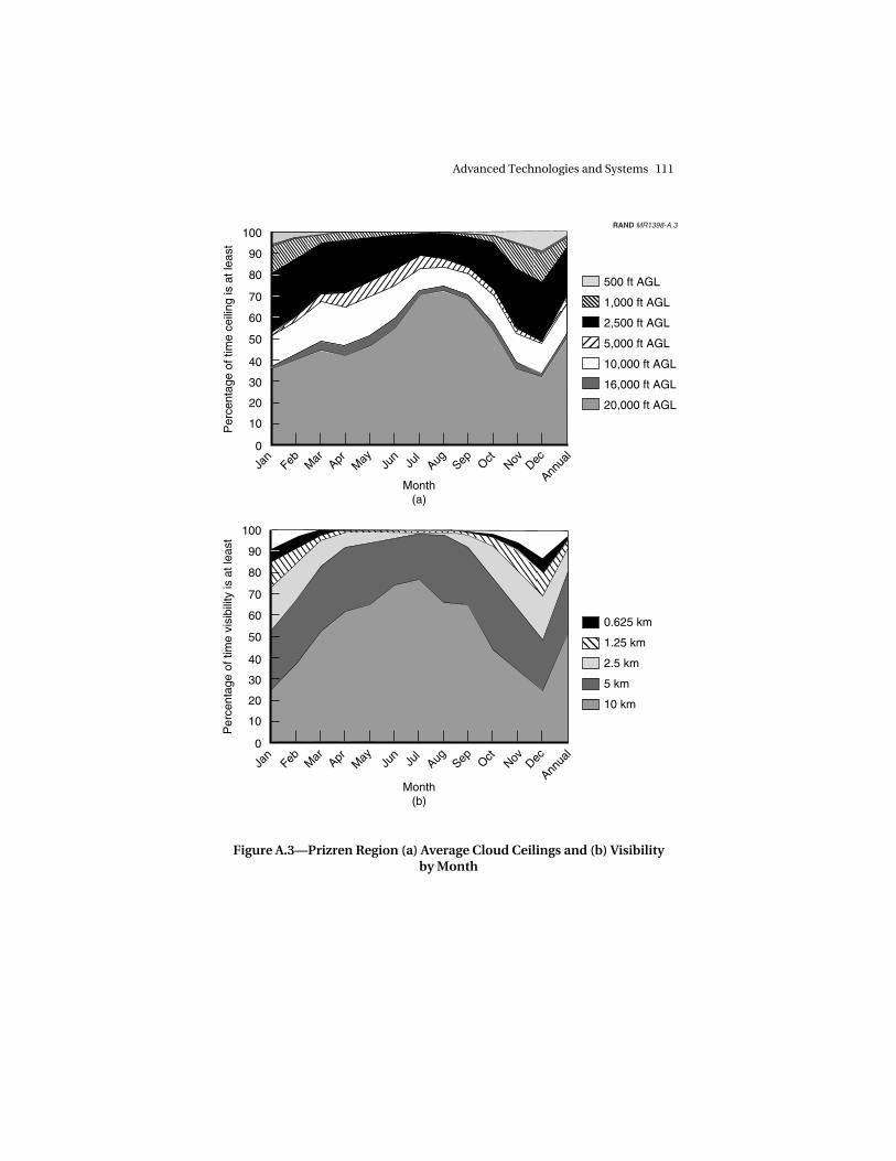
The medium- and high-altitude UAVs, combined with manned ISRaircraft and constellations of space-based collectors, will provide theUSAF’s suite of sensing capabilities at the altitudes above the prolif-erating Man-Portable Air Defense (MANPAD) threat. However, evenwith the enhanced airborne and space-based systems described inthis book, it is still often necessary to get under the weather and upclose to a target to obtain sufficient situational awareness toauthorize a strike. This is especially true in an environment of strictROE and in the absence of friendly ground forces.
Figure A.3 illustrates the weather challenge with weather data fromthe Prizren region of Kosovo. Ceilings vary with the season. On
______________ 16David A. Fulghum and Robert Wall, “Global Hawk Snares Big Break,” Aviation Week& Space Technology, October 23, 2000, p. 55.17A VHF-band FoPen radar antenna would be quite large and therefore difficult to in-tegrate into a Predator-size UAV.
Advanced Technologies and Systems 111
100
90
80
70
60
50
40
30
20
10
0
Jan
Feb Mar Apr
May Ju
nJu
lAug Sep Oct
Nov Dec
Annua
l
Jan
Feb Mar Apr
May Ju
nJu
lAug Sep Oct
Nov Dec
Annua
l
Per
cent
age
of ti
me
ceili
ng is
at l
east
Month(a)
Month(b)
100
90
80
70
60
50
40
30
20
10
0
Per
cent
age
of ti
me
visi
bilit
y is
at l
east
500 ft AGL
1,000 ft AGL
2,500 ft AGL
5,000 ft AGL
10,000 ft AGL
16,000 ft AGL
20,000 ft AGL
0.625 km
1.25 km
2.5 km
5 km
10 km
RAND MR1398-A.3
Figure A.3—Prizren Region (a) Average Cloud Ceilings and (b) Visibilityby Month

112 Aerospace Operations Against Elusive Ground Targets
average, a surveillance platform would have to fly below 4,000 ft tohave an 80-percent chance of having a cloud-free view of the ground.Air-deployed unattended ground sensors and smaller, expendableUAVs can fill this gap, to form a seamless web of collectioncapabilities from the ground through space.
Micro–Air Vehicles
The Defense Advanced Research Projects Agency (DARPA) is devel-oping micro–air vehicles (MAVs), which it defines as UAVs withmaximum physical dimensions under 15 centimeters (cm).18 At thistiny scale, MAVs have the advantages of being man-portable andmay eventually be able to navigate in confined areas, such as underforest canopies, in urban canyons, and inside buildings. However,their small size will limit MAVs to fairly short-range and endurancemissions, very small sensor apertures, and low-power transmissions.In addition, with typical flight speeds of 5 to 10 meters per second(mps), moderate winds will greatly affect their range, ground speeds,and maneuvering capability. Despite these limitations, MAVs will fillan important void in the U.S. military capability to find enemy forceshiding under trees or in buildings and to conduct immediate BDA ortag targets in these environments.19
MAV systems will require the application of several existing tech-nologies and some new technologies. For example, these small airvehicles operate beneath the envelope of most USAF flight experi-ence. Therefore, DARPA’s MAV program includes research in thefield of low-Reynolds-number20 aerodynamics for fixed- and rotary-
______________ 18James McMichael, “Micro Air Vehicles,” DARPA briefing at the Deputy UnderSecretary of Defense for Science and Technology (DUSD (S&T)) Seminar on EmergingTechnologies: Micro Air Vehicles, Alexandria, Va., December 11, 1998, http://www.dtic.mil/dusdst/docs/Dec98/microairvehicles.pdf, viewed September 25, 2000; andSam Wilson, “Micro Air Vehicles (MAV),” http://www.darpa.mil/tto/programs/mav.html, last viewed September 7, 2000.19Mark Hewish, “A Bird in the Hand: Miniature and Micro Air Vehicles ChallengeConventional Thinking,” Jane’s International Defence Review, November 1999,pp. 22–28.20The Reynolds number (Re) is a dimensionless parameter for characterizing the flowover a vehicle moving through the air or water. For our purposes, we focus on flowsover aircraft. It is defined as Re = ρVL/µ, where ρ is the air density, V is the velocity ofthe air flowing past the aircraft (essentially the flight speed), L is a characteristic length

Advanced Technologies and Systems 113
wing MAVs. In addition, volume and weight limitations make pro-pulsive efficiency a prime design consideration. DARPA is studyingbattery-powered, propeller-driven MAVs, as well as miniature jet androcket engines. Miniaturized guidance systems, sensors, communi-cations systems, aerodynamic control surfaces, and actuators arealso being developed and integrated. Although MAVs’ small sizeswill contribute to covertness, maneuverability, and transportability,design trades may drive production MAVs to be somewhat largerthan DARPA’s goal of 15 cm.
Deployment. To employ MAVs as a means of finding hiders inforests or in urban environments, the USAF must have a way of in-serting these sensor platforms into the vicinity of the target to besensed and must have a datalink to the engagement controller. LargeUAVs or manned aircraft flying above the surface-to-air threat couldfacilitate both of these actions in many scenarios. An individual MAVor clusters of MAVs can be carried and dropped from these larger airvehicles in a pod or missile, which would fly to the area of interestand then slow to the MAV’s flight regime before releasing them.Commands from the engagement controller and sensor data fromthe MAV could then be relayed through the launch aircraft or UAV. Ifthe insertion point is at long range, the MAV may be able to use asatellite’s datalink, or the delivery missile could deploy a separatedatalink on a small UAV.
Designing for Obstacle Avoidance. The operating requirementsassociated with flight under forest canopies and in buildings willdrive the designs of MAVs intended for those purposes. At this point,battery-powered, shrouded rotary-wing designs appear best suitedfor flight and imaging in these confined and complex environments.Further, these MAVs’ guidance packages must include searchalgorithms with obstacle-avoidance subroutines and the system’ssensors will have the additional duty of detecting obstacles that mustbe avoided. Passive imaging sensors may be the MAV’s primary
______________________________________________________________ (e.g., the chord of the wing measured from the leading edge to the trailing edge), and µis the viscosity of the flowing fluid (e.g., air is less viscous than honey or motor oil).Since ρ and µ are approximately the same for all aircraft at a given altitude, the MAV’suniquely low Reynolds numbers stem from their slow flight speeds and small physicaldimensions. Assuming the maximum MAV dimension of 15 cm for L and a flightspeed of 6 mps, a MAV’s Re would be approximately 1/1,000 of a small private aircraftand 1/10,000 of a large cargo aircraft or airliner.

114 Aerospace Operations Against Elusive Ground Targets
means for target detection/recognition and for fratricide/collateral-damage prognosis, but small radar or bat-like ultrasonic echo-locating sensors may be needed to provide target and obstacleproximity data. Alternatively, a single active sensor, such as a smallimaging laser radar, may accomplish both tasks. The guidancesystems should be capable of either autonomous searches orremote-controlled flight. Automatic target recognition algorithmswill have the challenging task of recognizing targets, as well asnatural and man-made obstacles, in these complex environments.For these reasons, these obstacle-avoidance MAV variants willprobably lag the simpler remotely piloted MAVs by many years.However, Draper Laboratory is working on a hovering MAV calledthe Kolibri, which is to include the obstacle-avoidance algorithms,autonomous and datalinked remote-control systems, miniaturizedINS-GPS, and sensors.21 The Kolibri weighs 320 grams (0.7 lb), ispropelled by a miniature diesel engine, and promises an impressive30 min of endurance.22 Figure A.4 illustrates two shrouded rotary-wing MAVs flying and hovering beneath a forest canopy to image ahiding TEL.
DARPA is also working on an extension to MAV capabilities in theirControlled Biological and Biomimetic Systems program. Studyingbiological organisms to understand and exploit their means of loco-motion, navigation, sensory fusion, and target recognition, thisprogram is developing insect-like sentinels that could be deployed togather information for the warfighter.23
Small UAVs
Filling the capability gap between MAE UAVs and MAVs, small USAFUAVs will fly close to the enemy, as do MAVs, making them vulnera-
______________ 21Neil Adams, “MAV Autonomous Operations,” Draper Laboratory briefing given atthe DUSD (S&T) Seminar on Emerging Technologies: Micro Air Vehicles, Alexandria,Va., December 11, 1998, http://www.dtic.mil/dusdst/docs/Dec98/microairvehicles.pdf, last viewed September 25, 2000.22Hunter Keeter, “DARPA Says MAV Acquisition Schedule Driven by Technology,”Defense Daily, July 29, 1999.23Alan Rudolph, “Controlled Biological and Biomimetic Systems,” http://www.darpa.mil/dso/, last visited October 3, 2000.

Advanced Technologies and Systems 115
RAND MR1398-A.4
Figure A.4—Micro–Air Vehicles Flying Below the Forest Canopy toImage a Hiding TEL
ble to attack by ground forces. And they will have relatively shortranges. In the absence of friendly ground forces to launch them, theywill need to be inexpensive one-time-use vehicles and will have to bedelivered to the target vicinity by a manned aircraft, larger UAV, ar-tillery round, or missile. Even so, by flying at several tens or evenhundreds of kilometers per hour, these air vehicles may be able tosearch tens to hundreds of square kilometers during a mission.Flying at hundreds of meters above the ground, they will operate un-der most cloud cover but will generally not be small enough to ma-neuver under forest canopies.
These systems will need to be able to transmit both images and theGPS coordinates of targets. Their onboard cameras will have to besmall and lightweight, have low power consumption, yet be ableto produce image quality at National Imagery Interpretability RatingScale (NIIRS)24 levels 7, 8 or 9, depending upon the mission and ROE.
______________ 24Image analysts use NIIRS scales (0 to 9) to quantitatively assess an image’s quality,or interpretability, which is a function of many factors, including illumination, sharp-ness, contrast, and picture size. NIIRS scales exist for the visible spectrum, as well as

116 Aerospace Operations Against Elusive Ground Targets
A small UAV may calculate a target’s location using an onboardactive sensor’s ranging capabilities and extrapolating from the smallUAV’s GPS coordinates, or it may solve this geometry problem usingan IPB-supplied digital terrain map of the region, along with its ownGPS coordinates and an onboard passive imaging sensor’s look an-gle. Many small UAVs have been designed and flown, and a wealthof experience is available from the model-airplane industry, sisterservices, and others.25
The U.S. Army defines small UAVs as having a range of 20 to 25 km,an endurance of 1 to 2 hr, a maximum wingspan of 4 ft, and a maxi-mum weight of 25 lb.26 However, many small-UAV designs vary insome aspects of this description. AeroVironment’s Pointer D-2 is anexample of a very lightweight small UAV. This 8-lb platform can op-erate for 1.25 hr using a lithium battery, has a 9-ft wingspan, and cancarry LLL TV, forward-looking infrared, or chemical sensors.However, lightweight airframes such as the Pointer D-2 are designedto be hand-launched and are too fragile for captive carriage underthe wing of a combat aircraft. Small-UAV designs can be strength-ened and designed with pop-out wings to permit low-drag carriageand deployment from larger air vehicles.
It is possible to design a completely new small UAV for USAF use;however, it might be faster, cheaper, and lower risk to adapt existingsmall air vehicles, such as DARPA’s Miniature Air-Launched Decoy(MALD)27 or the USAF’s LOCAAS, both of which can be captive-
______________________________________________________________ for radar, infrared, and multispectral images. On the visual scale, a NIIRS 1 imagewould allow an analyst to distinguish between a runway and adjacent taxiways. ANIIRS 7 image would permit individual railroad ties under a railroad track to be recog-nized. A NIIRS 9 image would allow an analyst to differentiate cross-slot from single-slot heads on aircraft panel fasteners.
The Federation of American Scientists has developed a tutorial on imagery intelli-gence, including descriptions of the four NIIRS scales mentioned above: “NationalImagery Interpretability Rating Scales,” http://www.fas.org/irp/imint/niirs/htm, vis-ited September 1, 2000.25“Unmanned Aerial Vehicles (UAVs),” http://www.writersg.com/milnet/pentagon/uavs/uavtab.htm, last visited September 29, 2000.26William Knarr, “A Family of UAVs—Providing Integrated, Responsive Support to theCommander at Every Echelon,” http://huachuca-usaic.army.mil/mipb/html%20Oct-Dec98/knarr/knarr.htm, viewed September 7, 2000.27Robert Wall, “Testing Expands Interest in MALD,” Aviation Week & SpaceTechnology, November 15, 1999b, pp. 84–85.

Advanced Technologies and Systems 117
carried and deployed from larger air vehicles, and are designed tocost approximately $30,000. The MALD has a flight speed of Mach0.9 and a range of over 550 km.28
The LOCAAS’ speed and range are lower than those of the MALD, butit already has a capable imaging and ranging sensor integrated withan ATR, and high speed may not be necessary or desired when col-lecting imagery at fairly close range. Therefore, we have chosen toemploy LOCAAS and variants of LOCAAS for our concepts of en-gagement, extending this system’s search and strike capability to ac-complish the dual roles of attack and surveillance.
Low-Cost Autonomous Attack System
The Low-Cost Autonomous Attack System, or LOCAAS, is a one-time-use folding-wing air-launched miniature cruise missile thatcan be deployed from aircraft, UAVs, missiles, or munitions canis-ters. As represented in Figure A.5, it has a 4-ft wingspan, weighs 85lb, and is propelled by a miniature turbojet engine.29 LOCAASsearches or cruises at 120 mps (Mach 0.35) for 30 min, giving it arange of 185 km, a search area capability of 50 sq km, or some com-bination of the two. AFRL has developed LOCAAS to autonomouslysearch for, detect, recognize, and kill critical mobile targets such astanks, TELs, and mobile SAM launchers. Using a laser radar (Ladar)seeker, it sweeps the search area with an infrared-wavelength laserbeam, sensing the reflected light to detect, image, and range targets.
The Ladar produces imagery with sufficient resolution for ATR pro-cessing. The system’s ATR compares the Ladar image of the sus-pected target to its target database in an attempt to recognize thevehicle. This capability includes some target-variation robustness,including turret and gun articulation. However, clouds and precipi-tation rapidly attenuate IR wavelengths. Although its search altitudeof 225 m AGL will usually keep LOCAAS flying beneath the cloud
______________ 28“Miniature Air-Launched Decoy (MALD),” http://www.darpa.mil/tto/Programs/mald.html, last visited September 29, 2000.29James Moore, “Powered Low Cost Autonomous Attack System,” Air Force ResearchLaboratory Public Release briefing, March 24, 1999; and Raymond Lopez, “USAFChooses LOCAAS Power,” Flight International, December 15, 1999, p. 18.

118 Aerospace Operations Against Elusive Ground Targets
Figure A.5—Powered LOCAAS in Its Flight Configuration and Foldedfor Captive Carriage
layers, LOCAAS will likely have difficulty imaging targets while flyingthrough precipitation or fog.
LOCAAS Operation. When LOCAAS detects and recognizes an objectas a valid target, it enters an engagement mode. In this mode, it fliesa glideslope from its 225-m search altitude to a point directly over thetarget. As it passes over the target, it fires a self-forging warhead inone of three modes. For hard targets, it fires in the “stretching rod”mode, which is optimized to penetrate a tank’s turret. If the weaponis fired from a greater height above the tank, the warhead forms an“aerostable slug,” which is designed to maintain its integrity for theselonger ranges and still penetrate the armored turret. If the target issofter, such as a TEL, the warhead will fire a directed fragmentation-blast pattern.

Advanced Technologies and Systems 119
This multi-mode device not only provides a robust killing capabilitybut also greatly limits the potential for collateral damage by restrict-ing the strike to the target—a stark contrast from the potential effectsof most gravity bombs and cluster munitions.
LOCAAS Plus: Adding a Datalink. A LOCAAS-like weapon would of-fer a strong addition to the USAF’s capability to defeat critical mobiletargets. However, a modest design enhancement on some of theLOCAAS weapons may provide much more robust capabilities andflexibility against elusive targets than are now planned. Specifically,we recommend adding a two-way datalink from the LOCAAS to thestrike aircraft and airborne command element, and adding a LLLvisual-spectrum motion-picture camera, slaved to the LOCAASLadar’s field of view. Rather than eliminating the system’s au-tonomous capability, these modifications would complement it byproviding for optional remote interaction. The datalink wouldtransmit visual imagery to an engagement controller and remote-control commands to the LOCAAS, enabling many new concepts ofoperation with this hybrid small UAV–cruise missile.
For example, when a LOCAAS has detected and recognized a targetand is closing in for the kill, the engagement controller can view theimagery to determine whether to proceed with the attack or termi-nate it. Unlike a terminal-phase no-go decision for an AGM-130, theLOCAAS would not be lost. It would simply revert to its search pat-tern, go around for another pass, or respond to other commandsfrom the engagement controller. The datalink could also provide avariety of other capabilities. When the appropriate search pattern isnot clear, one or a few LOCAAS could be remotely piloted to hunt fora target and then could be returned to autonomous operation for thefinal strike sequence against the designated target. Similarly, a re-mote operator could observe the imagery during a standard au-tonomous search pattern, but alter the search pattern if she noticessuspicious activity, such as a distinct vehicle trail, dust cloud, targetbeing covered by netting, or a new target of opportunity. If oneLOCAAS has just fired at the desired target with unknown results or ifthe engagement controller has confirmation of a camouflaged targetat a specific GPS coordinate, she could direct one or several LOCAASto abandon their searches, fly directly to the target, and either re-acquire and strike, or simply strike the target’s GPS coordinates usinga specified warhead mode. In this case, as each LOCAAS approaches

120 Aerospace Operations Against Elusive Ground Targets
the target area, its imagery could permit BDA of preceding LOCAASstrikes.
The flexibility provided by this range of operating modes would makethe LOCAAS much more robust against a variety of targets. It wouldalso add significantly to the enemy’s challenge of countering thesystem, since its operation would be much less predictable and sinceoptions for counter-counter measures would be more plentiful.Further, this capability could free the LOCAAS to be used with su-pervision in situations that ROE would otherwise make off-limits. Anexample of this added engagement freedom might be striking a tankin a convoy for which intermingling of civilians had not otherwisebeen ruled out. Similarly, the visual-band sensor would provide suf-ficient resolution to allow the engagement controller to recognizepersonnel and thereby gain confidence that groups of individuals areenemy soldiers, rather than friendly soldiers, human shields, or oth-erwise intermingled civilians. One uncertainty that may limit suchmovement to a man-in-the-loop LOCAAS is cost, which could bedriven up substantially by putting a stabilized TV or IR sensor onLOCAAS. If so, then perhaps only a small percentage of LOCAASwould have that feature for situations where it was essential.
Another alternative would be to produce a reconnaissance version ofLOCAAS whose sole purpose would be ISR and BDA. By replacingthe warhead with additional fuel, this configuration would form asmall, expendable UAV, which could have hours of on-station en-durance. This system could provide continuous imagery surveillanceunder cloud cover and/or at night to help fill the gap between en-durance UAVs and ground sensors. It could also be used to searchfor targets, provide target images with GPS coordinates, and thenprovide BDA imagery immediately after conventional LOCAASor other weapons have attacked the target.30 In addition, if theLOCAAS’ datalink transmissions are not sufficiently powerful toreach the launch platform, an appropriate communications satellite,or the Airborne Command Element, it may be necessary to use thisISR LOCAAS or another LOCAAS to relay the data.
______________ 30Wall and Fulghum (2000, p. 78) recommend a similar design modification, replacingthe warhead with a camera.

Advanced Technologies and Systems 121
ADVANCED RADAR
Radar is an active sensor methodology that can exploit many por-tions of the electromagnetic (EM) spectrum. Most radar systems aredesigned to use portions of the EM spectrum from UHF through Kaband (300–40,000 MHz). Some systems—including LOCAAS’ higher-frequency IR-band Ladar and the lower-frequency VHF Foliage-Penetrating (FoPen) radar system (described below)—operate out-side this range to exploit the unusual attributes of higher or lowerfrequencies. Because most weather is transparent to the commonlyused frequencies and because radar provides its own illumination,radars can be designed to be effective in nearly all weather condi-tions and at night.
In principle, a radar is a device that actively illuminates objects withEM radiation and measures the frequency, amplitude, and timing ofthe reflected radiation to determine the ranges and attributes of ob-jects. By also recording the precise angle from the radar to the ob-jects, the radar can be used to determine the relative positions of theobjects. As with other active sensors, radars require power for gener-ating their illuminating pulses, and these pulses can reveal their ownpresence and location. Very high-payoff capabilities for reconnais-sance and surveillance radar systems include moving-target indica-tor (MTI) and synthetic aperture radar (SAR), and in some cases,FoPen radar.
Moving-Target Indicator Radar
Moving-target indicator radar systems can be designed to detect andtrack moving airborne (AMTI) or ground (GMTI) targets. The fun-damental difference between these two systems’ functions is thespeed of the targets. As a radar pulse reflects off of a moving target,its frequency shifts slightly, by a magnitude related to the velocity ofthe target. MTI systems use this Doppler shift in frequency to distin-guish moving objects from their stationary surroundings. EmergingGMTI radar capabilities should provide waveforms that can permitsome degree of classification of detected targets. Assuming that thedesired targets are vehicles with distinct characteristics, this classifi-cation process may be able to filter out the vast majority of civiliantraffic from consideration. The GMTI system can then cue a SAR to

122 Aerospace Operations Against Elusive Ground Targets
image the remaining targets in order to continue the filtering andrecognition process.
Synthetic Aperture Radar
Synthetic aperture radar exploits its own platform’s forward motionto permit the radar’s antenna to collect reflected radiation over apredetermined distance along the platform’s flight path, as if it hadan antenna that was as long as that distance. The data collected bythis large virtual, or synthetic, aperture is then processed to create animage of the area or objects being illuminated. A SAR can be used tocreate a digital terrain map of a region, survey a large area, or, in a“spotlight” mode, to scrutinize an area with higher resolution byemploying a larger synthetic aperture.
Digital terrain maps are useful for IPB development, mission plan-ning, precision targeting, placing ground sensors and interpretingtheir results, and providing a baseline for change-detection pro-cesses. A SAR variation called interferometric SAR (IFSAR) signifi-cantly improves terrain height measurements. A single-pass IFSARemploys two antennas in proximity but offset slightly on the cross-track plane (perpendicular to the direction to the target), resulting invery slight differences in distance from the target to each antenna.By comparing the phase differences of the signals received by eachantenna and resolving the associated geometry, terrain heights canbe measured with a precision approaching the wavelength of mi-crowaves.31
SAR imaging complements GMTI by providing a higher-resolutionimage of the area of interest, but it can only image stationary targets.A variation, called inverse SAR (ISAR), exploits a target’s motion toimage it. ISAR is a set of techniques for forming a SAR image of amoving target, in which the motions of both the radar and the vehi-cle are compensated to cohere the synthetic aperture. The relativemotion (not just the sensor platform motion) is employed to sweepout the aperture. To cohere is to adjust the target-to-radar phaserelationships from pulse to pulse along the synthetic array to match
______________ 31George Stimson, Introduction to Airborne Radar, 2nd ed., Mendham, N.J.: SciTechPublishing, 1998, pp. 515–518.

Advanced Technologies and Systems 123
those that prevail along the usual kind of static phased array. As witha static phased array, the deviations cannot exceed a fraction of awavelength without degrading the resolution and blurring the image.At X-band, this would require compensating for platform and targetmotion down to less than a centimeter. On the platform, modern in-ertial navigation systems are adequate, even if imaging is done at 0.3-m resolution (requiring about 14 sec for a satellite to traverse a 100-km aperture at 2,000-km range).
Target-motion compensation is more problematic. Conceptually, avehicle is tracked in an attempt to develop a rough motion estimate,then an image is formed at low resolution (where there is likely to beless smearing) to localize one or more large scattering centers. Next,a simple parametric model of the vehicle dynamics may be devel-oped to try to solve for the model’s free parameters by adjusting thephase corrections until the strong scattering centers are well re-solved. Objective measures of goodness for the image can be de-fined, and these may be used to automate this “autofocus” opera-tion. More-sophisticated versions of this conceptual scheme exist, ofcourse, but they share a fundamental inability to fully compensatefor random motions from pulse to pulse. Substantial image degra-dation should be expected on unpaved rural roads, such as thosethat mobile missiles might use in rural China.
So far, we have discussed the ISAR case, in which the radar platformsupplies the motion used to sweep out the synthetic aperture. If thetarget moves along a curved portion of roadway, such that the targetaspect changes rapidly by several degrees, then the synthetic aper-ture can be formed much more rapidly. This may help with theproblem of road roughness, since it is more likely a short stretch ofsmooth road can be found than a long stretch. For example, if theseveral-degree turn takes 2 sec at 40 knots, only 40 m of smooth roadis required.
The Joint STARS program has looked extensively at this question andhas used maps of road networks to identify appropriately curvedportions of roads where ISAR could be performed more effectively.Presumably, if IPB data were to be collected over an extended pe-
124 Aerospace Operations Against Elusive Ground Targets
riod,32 ISAR techniques could be tested on vehicles traversing thesestretches to determine which were sufficiently smooth to producegood images. Then, if targets are tracked for long intervals during aconflict, eventually they will pass over these smooth stretches or stopsomewhere and can be imaged at high resolution with ISAR or SAR.33
Foliage-Penetrating Radar and the Change-Detection Process
In many parts of the world, foliage is one of the most abundant andmost effective concealment resources available to military forces.Forests (both tropical and temperate) allowed U.S. adversaries inVietnam and Kosovo to conduct substantive military combat and re-supply operations, despite extraordinary efforts to stop them. Onepotential solution to the problem of finding forces hiding under for-est canopies is to have sensors that can peer through these canopiesto detect and distinguish military targets. Although foliage is fairlytransparent to some sensors, physics presents a number of chal-lenges to practical implementation.
For example, campers in a thick forest would not expect direct sun-light in their camp, but they would expect their radios to work, as-suming that the campsite was within range of a transmitter: AM andFM radio transmissions, which lie in the UHF, VHF, and lower-frequency bands of the EM spectrum, penetrate foliage with rela-tively little attenuation,34 as Figure A.6 indicates. It is possible todesign radar systems to sense these relatively long wavelengthsthrough forest canopies. As an added benefit, these wavelengths alsodefeat most camouflage netting, including netting designed tocounter the more common, higher-frequency radar transmissions.Using 1- to 10-meter-long EM waves of the very high-frequency(VHF) band, foliage penetration is good and the antenna sizes are
______________ 32Ideally, this IPB would be done during peacetime. Standoff airborne platformscould do some IPB. However, for really large denied areas, such as interior China, aspace-based system would be needed.33We are indebted to RAND colleague Joel Kvitky for providing this technical discus-sion of ISAR.34VHF = 30–300 MHz; UHF = 300–3,000 MHz; AM radio = 0.55–1.72 MHz; FM radio =88–108 MHz; television = 45–890 MHz.

Advanced Technologies and Systems 125
Sig
nal p
enet
ratio
n
Sen
sor
reso
lutio
n
Recognize targets,assess collateral damage potential, conduct BDA
Detect under foliage
All-weather sensing
VHF UHF
FoPen
Microwave Millimeterwave
Infrared Visual0
RAND MR1398-A.6
Imaging sensors
Figure A.6—Resolution and Penetration Characteristics of theElectromagnetic Spectrum
manageable aboard aircraft. However, the resolution possible fromVHF radar is typically no better than a few meters. In contrast,excellent sensor resolution is available by using very shortwavelengths, such as the visual (electro-optical [EO]) or infrared (IR)bands of the EM spectrum. However, these wavelengths are almostcompletely absorbed or reflected by foliage. The ultra-high-frequency (UHF) band provides some foliage penetration whileoffering somewhat better resolution than VHF frequencies.
Developing FoPen Technologies. Technologies for detecting largevehicles under forest canopies are the goal of a program the AFRLSensors Directorate is teamed on with the Army, DARPA, andLockheed-Martin, entitled “FoPen SAR for Global Hawk.” Such

126 Aerospace Operations Against Elusive Ground Targets
technologies would have a probability of detection of at least 80 per-cent and a maximum false-alarm rate of 0.1 per square kilometer.35
In the program, a VHF FoPen SAR (25–88 MHz) is used to detect largeobjects under trees. Unfortunately, the VHF SAR’s coarse, 2–3-m,resolution makes it impossible to recognize targets from theseradars’ returns; even classification is limited to the general character-istics of large man-made metallic objects. The VHF FoPen detectionswill likely also include many false alarms, since other man-made ob-jects, some configurations of clustered trees, and a variety of terrainfeatures can produce target-like radar returns. Therefore, these VHF-detected potential targets act as cues for a wider-band UHF SAR(150–572 MHz), which filters out many false alarms by conductinglocalized searches in the immediate vicinity of the cues. The UHFSAR will have poorer foliage-penetration capabilities than the VHFSAR; however, it should be adequate for localized searches, and theUHF’s sub-meter resolution should permit the discrimination of in-dividual trees, as well as the scattering centers that are typical ofman-made objects. This system will transmit UHF SAR images of the35 × 35 meter areas around suspected targets to an engagement con-troller and his support team for further filtering and tasking ofhigher-resolution sensors.
AFRL’s employment concept includes substituting Global Hawk’splanned X-band (8,000–12,500 MHz) SAR with FoPen VHF and UHFSARs. Their current design is already 85-percent form-fit-function–compatible with the Global Hawk.36 This Global Hawk–based VHFSAR will be able to search up to 1,400 sq km/hr. Unlike some large-area surveillance systems, such as Joint STARS, that can function ef-fectively at single-digit look-down angles, FoPen systems mustmaintain much greater look-down angles—30 to 60 degrees is theideal range—to avoid excessive interference by obstructions such as
______________ 35Personal interviews with Ms. Laurie Fenstermacher, Mr. Ed Hamilton, Mr. ZdzislawLewantowicz, Mr. Dennis Mukai, Mr. Steve Sawtelle, Lt Col Steve Suddarth, Mr.Vincent Velten, and Mr. Edmund Zelnio at AFRL/SN, Wright-Patterson AFB, Ohio,February 29, 2000.36Since a FoPen’s long VHF wavelengths would be susceptible to refraction by theionosphere if the FoPen SARs were space-based, FoPen systems will be limited to air-borne platforms until this technical challenge can be overcome. Personal interview,Mr. Dennis Mukai, Wright-Patterson AFB, Ohio, July 5, 2000.

Advanced Technologies and Systems 127
tree trunks. Therefore, airborne FoPen platforms will not be able tostand off as far as Joint STARS does.
Change Detection. Following Operation Allied Force, the Chief ofStaff of the Air Force asked AFRL to identify a near-term solution tothe problem of finding critical mobile targets hiding under forestcanopies. In response, the Information, Munitions, and SensorsDirectorates are working together on a program entitled “TanksUnder Trees” (TUT). TUT exploits the capabilities of the VHF andUHF FoPen systems described above in a process called change de-tection. At its current state of maturity, the VHF FoPen system maygenerate many more false alarms than the number of actual targets.Therefore, rather than attempting to determine the nature of everydetection, the change-detection process requires the VHF SAR sys-tem to map the same areas periodically, and essentially subtracts aprevious digital map from the most recent map to reveal changes inthe returns from these large objects, using the rationale that vehiclesthat have moved from one location to another may have caused thedetected changes.
Assuming that the change-detection process eliminates the majorityof the VHF SAR’s false alarms, the remaining detections serve as cuesfor the UHF SAR. In addition, the detected changes will cue searchesof other relevant sensor databases. For example, a variety of ISR sys-tems may have historical databases that could be reviewed to lookfor clues about targets moving into or out of a location where achange has been detected. If an engagement controller determinesthat a change was probably caused by enemy activity, he could taskvarious sensors to take a closer look. For example, UAVs, mannedaircraft, or a satellite could image the target from various aspect an-gles. The controller might also task airborne or space-based GMTIsystems to monitor the vicinity for further indications of vehicles en-tering or leaving their hides.
While TUT’s FoPen-based change-detection system will not provideinstantaneous detection and recognition, it appears to offer thegreatest near-term potential for detecting large military vehicleshiding in forests and is a good complement to GMTI capabilities.

128 Aerospace Operations Against Elusive Ground Targets
HYPERSPECTRAL IMAGING
Offering strong and complementary capabilities to other current andplanned sensor systems, hyperspectral imaging (HSI) sensors pro-duce images that normally include information from the visible aswell as the infrared spectrum, and they provide a spectral characteri-zation of the electromagnetic radiation incident on each of the sen-sor’s pixels. Like other imaging systems that operate at these shortwavelengths, HSI systems detect EM radiation that is reflected oremitted primarily from the surfaces of objects.37 Each surface mate-rial has a unique spectral signature. Given sufficient spatial andspectral resolution, HSI systems can often reveal man-madeobjects—even those that would be overlooked by an image analystscanning a high-resolution photograph. HSI data can be used se-quentially, first to detect and analyze suspicious (non-natural) spec-tral fingerprints and then to provide images of the suspected targetand its surroundings to an engagement controller.
The visible and infrared portions of the EM spectrum are conven-tionally divided into the visible (0.38–0.76 micrometers [µm]), verynear infrared (VNIR: 0.76–1.0 µm), near infrared (NIR: 1–3 µm),middle infrared (MIR: 3–8 µm), longwave infrared (LWIR: 8–14 µm),and far infrared (FIR: 14–50 µm) bands. Hyperspectral imaging sen-sors can be designed to use any of these wavelengths, and many ex-ploit segments of the visible, VNIR, NIR, MIR and LWIR bands,38
dividing them into much smaller segments to obtain spectral resolu-tion on the order of 10 nanometers (nm).39 Most current HSI designsuse tens to hundreds of small spectral bands.40 This detailed spectralanalysis of each image essentially multiplies the quantity of sensordata relative to a comparable photograph, and the supporting
______________ 37Dr. David Lewis points out that the next step in this lineage of sensing is ultraspec-tral imaging, which will have sufficient resolution to detect emissions or absorptionfrom the atmosphere. Clearly, this improvement goes beyond sensing emissions fromthe surfaces of objects. Personal communiqué with Dr. David Lewis, AFRL SpaceVehicles Directorate, Albuquerque, N.M., October 24, 2000.38Nicholas M. Short et al., “The Remote Sensing Tutorial,” last updated June 2000,http://rst.gsfc.nasa.gov/pdf/Sect13.pdf, pp. 62–65, viewed August 31, 2000.39One meter = 103 mm = 106 µm = 109 nm.40Similar devices that employ a few, much broader, frequency bands are calledmultispectral imagers.

Advanced Technologies and Systems 129
datalink bandwidth and/or processing power requirements scaleproportionately.
Advantages of HSI Systems
Examining the spectral content within a given pixel, the HSI systemcan detect distinctive spectral fingerprints that reveal specific ob-jects, including camouflage nets and paint, and metal surfaces. Infact, a target that subtends a small fraction of a pixel can still be de-tected, given sufficient SNR and spectral contrast. In addition, be-cause HSI analysis algorithms sense spectral signatures rather thanvehicle silhouettes or major features—as do most other imaging-system ATR algorithms—partially obscured targets can be detectedand, under some conditions, distinctive spectral content in lightscattered by a forest canopy can reveal the presence of targetsbeneath the canopy.
Another advantage of HSI ATR processing is that it requiresdatabases of one-dimensional spectral signatures, rather than thetwo- or three-dimensional database elements used by some otherimage ATR systems. This advantage would tend to offset the addeddemands of having to examine every pixel. Further, while the visualand shorter-wavelength IR bands’ signatures are greatly reduced atnight, the MIR and LWIR bands remain effective.41 However, bothvisible and IR bands are absorbed and/or scattered by clouds andprecipitation.
Components of HSI Systems
HSI sensor systems consist primarily of optics, a spectral dispersingdevice (similar to a sophisticated prism to divide the light across thespectrum), a sensing component, recording and transmitting de-vices, a power supply, a processor, and processing algorithms.Because the wavelengths are shorter than those of most radar sys-tems, the aperture (optical lens) can be as small as a few inches fora low-flying UAV. Therefore, these sensor systems can fit on a
______________ 41Personal interview with Mr. Mike Eismann at AFRL/SN, Wright-Patterson AFB,Ohio, February 29, 2000.

130 Aerospace Operations Against Elusive Ground Targets
LOCAAS-size UAV. Most space-based HSI systems would have pro-portionately larger lenses to retain resolution and SNR from orbitalranges. The high speed at which their sensing elements can becharged and discharged to capture sequential images make charge-coupled devices the sensing instruments of choice for most HSI sys-tems. A charge-coupled device, which is also the sensing instrumentin a digital camera, is an array of very small semi-conducting chipsthat are charged by incident radiation. Because HSI systems arepassive collectors, their power requirements are relatively low.
Operational Use
Operationally, HSI systems could be used independently to searchfor targets along LOCs, or they could be cued by wide-area surveil-lance systems to investigate suspected hiding areas. For example,when a FoPen radar detects a change in an area that IPB indicates isa likely target operating area, the engagement controller could cue anHSI system on a UAV or satellite to investigate the potential target.
SPACE-BASED SURVEILLANCE
Orbiting satellites are practical platforms for many types of sensors.Space-based sensors can remain in orbit for years, are difficult toattack, do not put U.S. warfighters in harm’s way, and do not requireextensive logistics support in the combat theater. Moreover, theiraltitude allows them to overfly any country without enteringsovereign airspace. This altitude, combined with their velocity, re-sults in greater and dynamic diversity of perspective and mitigatessome of the masking problems caused by terrain, trees, or buildings.These attributes offer the potential for conducting detailed digitalmapping and photography for observing military training, prepara-tions, massing, or other operations.
Most of the sensor phenomenologies that are effectively employedby airborne sensors are also useful from space. Infrared and electro-optical systems, including hyperspectral imagers, SIGINT sensors,and a variety of radar systems can all provide valuable data. With the
Advanced Technologies and Systems 131
exception of HSI,42 the United States currently employs these phe-nomenologies from space, but improved coverage is needed.
SBIRS Satellites
The Defense Support Program uses IR sensors in geosynchronousorbit to detect and track missile launches and recognize missiletypes. Analyzing a missile’s trajectory reveals the approximatelaunch location and destination. This constellation is scheduled tobe replaced by the Space Based Infrared System (SBIRS),43 which willprovide similar, but enhanced, capabilities, including battlespacecharacterization and tactical intelligence. SBIRS will consist of foursatellites in geosynchronous orbit, two in highly elliptical orbits,several in low earth orbits, and an integrated network of groundstations.
Satellite Radar Systems
If they prove feasible, advanced space-based radar systems couldcontribute immensely to the Air Force’s warfighting capabilities. Thedeployed constellations might include AMTI, GMTI, and SAR (con-ventional SAR, ISAR, and IFSAR) capabilities, as described above.
Satellite constellation design factors include required coverage rates,orbital altitudes and periods, solar radiation exposure, satel-lite/sensor power requirements, and acquisition/launch costs. Oneless-obvious factor relates to the fields of regard of SAR and MTIradar systems. The background clutter directly below a satellite re-duces the signal-to-interference ratio to unusable levels for MTI sys-tems. Therefore, spaceborne MTI radars are designed with a toroidal(donut-shaped) field of regard, which excludes the region directlybelow the radar. Similarly, a SAR’s ground range resolution is in-
______________ 42In July 2000, the Air Force Research Laboratory launched MightySat II.1 with an ex-perimental HSI sensor and high-efficiency recognition algorithms onboard. In addi-tion, MightySat II.2 is planned to fly an ultraspectral imaging system sometime in2002. AFRL provides a summary of the MightySat II program at “MightySat II Satel-lites,” http://www.vs.afrl.af.mil/factsheets/msat2.html, last visited October 6, 2000.43SBIRS Program Office, “Space-Based Infrared System Brochure, Space and MissileSystems Center,” 185 Discover Blvd., Suite 2512, El Segundo, Calif. 90245, http://www.losangeles.af.mil/SMC/MT/sbirsarc.htm, last visited September 6, 2000.

132 Aerospace Operations Against Elusive Ground Targets
versely proportional to the cosine of the radar beam’s depressionangle, creating a region of very poor resolution near the nadir, theline on the Earth’s surface directly below the radar’s flight path. Aswell, the azimuthal resolution in the forward and rear directionsrelative to the aircraft’s flight path is degraded as a result of the di-minished projection of the synthetic aperture baseline in those di-rections. Consequently, the SAR’s field of regard is in the shape of apair of unfolded butterfly’s wings.
Despite these complicating geometric considerations, satellite con-stellations can be configured to provide any level of coverage desired,from intermittent through redundant coverage, which reduces thecoverage problem to one of cost. While it might seem that near-continuous coverage would result in only a slight operationalcompromise as compared with complete coverage, actual coveragegaps are effectively extended by the time required to reacquire atarget’s track. In the near term, it is unlikely that a robust system canbe developed to rapidly and reliably reacquire target tracks lostduring gaps in GMTI coverage. Thus, continuous GMTI coverageand complementary ISAR coverage are desirable, facilitating smoothhandoffs of target tracks from one satellite to the next and imagingsuspected targets rapidly, especially in an environment with heavycivilian traffic, significant obscuration, or complex terrain.
We should note, however, that the cost of a GMTI constellation suffi-ciently large to provide near-continuous coverage of China could behuge: over $40 billion by a recent RAND study’s estimates. Thatstudy concludes that high-altitude stealthy UAVs carrying GMTIradars could actually be survivable against advanced SAMs, butwould be highly vulnerable to attacks from fighter aircraft. If somemeans were found to protect UAVs from fighter attack, they mightoffer a cost-effective alternative, or complement, to space-basedGMTI.44
The USAF is developing advanced space-based radar technologies.The Discover II program was a USAF, DARPA, and National Re-connaissance Office program to develop and demonstrate affordablespace-based radar, including GMTI and SAR-ISAR capabilities. As
______________ 44Glenn Buchan et al., “Intelligence, Surveillance and Reconnaissance (ISR) Force MixStudy: Summary Briefing,” Santa Monica, Calif.: RAND.

Advanced Technologies and Systems 133
this report was being written, concerns over the maturity of the tech-nology and questions about which service should steward the DoD’sfuture large-constellation space-based radar system caused Congressto eliminate funding for this program.45 However, applicable tech-nology programs continue in government laboratories and industry.
HYPERSONIC MISSILES FOR RAPID RESPONSE STRIKES
Today’s cruise missiles can be launched from ground-, sea-, or air-based platforms. Most existing cruise missiles fly at subsonic speeds.The Russian Sunburn and French ASMP are examples of ramjet-powered supersonic cruise missiles. In the 1960s and early 1970s, theUSAF inventories included ramjet-powered Mach 3+ BOMARC sur-face-to-air missiles. In the 1980s, the USAF successfully flight-testedthe prototype Mach 4+ Advanced Strategic Air-Launched Missile(ASALM).
Hypersonic flight is usually defined as atmospheric flight at speedsabove Mach 5. To date, the world’s experience with manned hyper-sonic flight is limited to brief flights of rocket-powered test vehicles,such as the X-15 and X-24, and transitory flight of space launch vehi-cles ascending through, or spacecraft reentering through, the upperatmosphere. However, several nations are developing technologiesto permit sustained hypersonic flight. The United States, Russia, andFrance have the most mature technology bases.
Technology Challenge: Air-Breathing Propulsion and FuelSystems
The integrated air-breathing propulsion and fuel system poses theprimary technology challenge for sustained hypersonic flight. Air-breathing engines, rather than rockets, will be used for sustained(cruising) atmospheric flight, owing to their greater fuel efficiency.By definition, rockets carry their fuel oxidizer onboard; air-breathingengines use the atmosphere as their oxidizer source. As a result,rockets are a good choice when the flight vehicle’s design require-ment is for short duration but very high thrust-to-weight-ratio
______________ 45“Space Radar on Death Row, Appeal Pending,” Defense Week, June 19, 2000, p. 1.

134 Aerospace Operations Against Elusive Ground Targets
propulsion; air-breathers are appropriate for efficient, sustained ac-celeration, and/or cruising flight.
The USAF, U.S. Navy, DARPA, and NASA46 are working with industryto advance the technology base for supersonic combustion ramjet(scramjet) engines.
Ramjets and scramjets differ from the more common turbojet andturbofan air-breathing engines found in current U.S. civilian andmilitary aircraft and missiles in the way they compress air prior tocombustion. Turbojets and turbofans use rotating turbomachinerycomponents called fans and compressors to compress air, and usesimilar rotating components called turbines to drive the fans andcompressors. In contrast, ramjets and scramjets use the ram effectcreated by their high speed to compress the air needed by their com-bustor, precluding the need for expensive rotating turbomachinery.However, this compression process also limits ramjets and scramjetsto efficient operation at supersonic and hypersonic speeds, respec-tively. Therefore, these systems must be boosted to their operatingspeeds by rockets or by combining these high-speed cycles with alow-speed cycle to form a rocket-based combined cycle or a turbo-ramjet or turboscramjet combined cycle.
A scramjet is similar to a ramjet in concept, except that the ramjetengine slows the inlet air to subsonic speeds in preparation for thecombustion process. Scramjets slow the inlet air from its initial hy-personic speed to supersonic speeds prior to entering the engine’scombustor, which is why the class of engines is called “supersoniccombustion ramjet.” Keeping the flow through the combustor su-
______________ 46NASA is conducting an independent, yet complementary, hypersonic technologydevelopment and flight demonstration program focused on hydrogen-fueled vehicles.NASA is scheduled to fly three X-43, Hyper-X, test vehicles at Mach 7 and 10, withinthe next two years. (The first of these test flights failed in 2001 when the boost vehiclewent out of control.) The X-43 is a 12-ft, one-time-use flight-test vehicle with ahydrogen-fueled scramjet engine. Because this scramjet is not thermally protected, itwill operate for only a few seconds during its flight. However, during that time, theUnited States should learn valuable lessons regarding hypersonic aerodynamics, flightcontrol, propulsion, and flight testing. A combined Langley Research Center–DrydenResearch Center team manages the Hyper-X program. Langley is responsible for hy-personic technology development, and Dryden is responsible for the program’s flighttesting. MicroCraft Inc. is the X-43 prime contractor. NASA has offered to integratethe USAF Hypersonic Technology (HyTech) engine on its Hyper-X vehicle as thefollow-on X-43 test program.

Advanced Technologies and Systems 135
personic prevents the engine from melting and the generally un-desirable high-temperature effects known as disassociation and ion-ization are retarded. However, leaving the flow above the speed ofsound during its entire transit time through the engine limits thetime available to slow the air, mix the air and fuel, burn the mixture,and reaccelerate the combustion products, to around 1 millisecond.Because the engine’s efficiency is heavily dependent upon the vehi-cle’s ability to minimize shock-wave losses, hypersonic vehicle de-signs are carefully integrated and typically use the airframe’s fore-body to form the engine inlet and the aftbody to form the expansionramp for the engine’s propulsive nozzle.
The Air Force Research Laboratory’s Hypersonic Technology(HyTech) program is developing a missile-sized scramjet engine,which has growth potential for larger, reusable, and/or manned ve-hicle applications. This engine is designed to accelerate from Mach4+ to any Mach number up to Mach 8, and then cruise for severalminutes. It burns standard jet propellant (JP) fuels. However, beforeit is injected into the combustion chamber, the scramjet’s fuel flowsthrough the engine walls’ catalyst-lined cooling passages, therebycooling the engine and breaking down the fuel into hydrogen andsimple hydrocarbons, such as methane, ethane, propane, and ethy-lene. These heated, simpler constituents will burn much more read-ily than will the complex hydrocarbon molecules in JP fuels. A fuel-cooled engine structure may seem too expensive for an expendablemissile; in fact, it should cost less than the turbine engines used insubsonic cruise missiles. DARPA estimates that the scramjet enginewill also cost significantly less than the simple solid rockets thatwould boost a cruise missile to scramjet-takeover speeds.
The U.S. Navy, through its relationship with Johns Hopkins Uni-versity’s Applied Physics Laboratory, is developing another missile-sized, JP-fueled engine called the Dual-Combustor Ramjet. Thisengine employs a fuel-rich ramjet combustor flowing one-third ofthe engine’s total inlet air as a pilot for the scramjet combustor.Since neither the pilot nor the scramjet combustor is actively cooled,the engine has a maximum Mach number limit of 6.5.47
______________ 47For further background on the physics and engineering issues related to hypersonicflight and propulsion, see William Heiser and David Pratt, Hypersonic Airbreathing

136 Aerospace Operations Against Elusive Ground Targets
Other Technology Challenges
The other key technology challenges for hypersonic cruise missilesinclude flight-testing an integrated air-breathing hypersonic vehicleand possibly improving high-temperature materials.
Thermal Protection. The temperatures and thermal loads at theseflight speeds far exceed those experienced by current U.S. aircraftand cruise missile airframes. However, they are not as high over theentire vehicle as one might think. The stagnation temperature of aflow increases as the square of the Mach number, with some reliefdue to vibrational modes, dissociation, and ionization of the atmo-sphere’s molecules at high Mach numbers. However, if the flow isnot stagnated or slowed to subsonic speeds near the vehicle, the air’stemperature will not rise to the stagnation temperature and will notcreate the extreme heat loads on that portion of the vehicle.48 Thehottest regions on air-breathing Mach 8 flight vehicles will be un-cooled portions of the engine combustor and nozzle, which couldreach 5,500°F; the inlet duct, at up to 4,000°F; and any unswept lead-ing edges, which could reach 3,500°F. Most other componentsremain well below 2,000°F.49 By way of reference, the temperatureof the air and high-stress turbomachinery just upstream of the com-bustor in a modern high-performance fighter engine is also between1,000 and 2,000°F, and the combustor and downstream componentsmust be actively cooled and/or thermally isolated to keep thesecomponents well below the temperature of the combustion prod-ucts. Similarly, cooling the hypersonic missile’s hottest componentswill require active cooling techniques (cooling fluid flowing throughheat exchangers or a similar approach), ablatives, or high-tempera-ture structures.
The U.S. space program has accumulated extensive experience withthermally protecting structures: regeneratively cooling rocket noz-
______________________________________________________________ Propulsion, AIAA Education Series, Washington, D.C.: American Institute ofAeronautics and Astronautics, Inc., 1994.48Viscous flows will, of course, comply with the no-slip condition where the boundarylayer meets the air vehicle’s skin. However, if the flow is at high speed just outside theboundary layer, the static temperature in the boundary layer will be well below thestagnation temperature and the heat loads on the vehicle will be much lower thannear stagnation regions.49Johns Hopkins APL Technical Digest, Vol. 14, No. 1, 1993, p. 25.

Advanced Technologies and Systems 137
zles and adding a layer of ablative tiles to protect vehicle skins. Theactive-cooling techniques and thermal-barrier coatings used in con-ventional jet engines, along with a variety of other cooled or ther-mally protected devices, add to this experience base. Therefore,advances in materials technologies are not required to produce anaffordable, expendable, unmanned hypersonic missile, althoughthey could enhance the design and further reduce the cost.
Apart from the main airframe and engine structural components,one potential application for advanced materials is high-temperatureapertures for sensors. For example, today an EO sensor on a Mach 8vehicle would probably require a sapphire window, whose cost maynow be acceptable for an expendable cruise missile application. Thedual-use applicability of sapphire for high-temperature windows, aswell as for bar-code scanner apertures, fiber-optics, and transducers,has brought down its costs. Nonetheless, current missile conceptsemploy GPS-INS guidance, and deploy lower-speed smart submuni-tions if terminal sensing is required. 50
Flight Testing. The requirements for hypersonic flight testing stemprimarily from unforeseen system and operational-level issues thatoccur when new technologies are integrated into complex devices tobe operated in new environments. These flight tests should revealremaining technical issues and help guide the field of hypersonics asit moves from expendable missiles to larger, reusable, and mannedcruise and space launch vehicles. Again, our nation’s space pro-grams and previous flight-test programs, such as the rocket-poweredX-15, will provide a good foundation for scramjet-powered vehicleflight tests.
DARPA’s Affordable Rapid Response Missile Demonstrator (ARRMD)program may flight test a prototype hypersonic cruise missile in thenext few years. ARRMD competitively selected the two JP-fueled en-
______________ 50Operating concepts must also be carefully considered prior to committing the re-sources to integrate an imaging sensor into a hypersonic weapon. By the time a hy-personic weapon is close enough to image a target with a useful resolution, the missilewill likely be within a few seconds of target impact—probably not sufficient time foran imaging ATR or a human to analyze the image and provide heading corrections,and for the aerodynamic control surfaces to accomplish terminal maneuvers prior toimpact. However, offboard sensors could update GPS coordinate targeting informa-tion earlier in the missile’s flight.

138 Aerospace Operations Against Elusive Ground Targets
gines described above, along with corresponding airframe configu-rations, as parallel design paths. Budget constraints caused DARPAto make an early decision to focus solely on the Air Force mis-sile/engine configuration. Subsequently, further budget constraintsforced DARPA to put the program on hold, and the Office of theSecretary of Defense has asked the services, DARPA, and NASA to de-velop a National Hypersonics Plan to be completed in fiscal year2001. A revived ARRMD program is a potential near-term element ofthis plan.
DARPA’s ARRM (USAF variant), at 168 in., is sized for carriage oncurrent USAF and U.S. Navy strike aircraft, including fighters andbombers.51 Its strap-on rocket boosters accelerate the cruise missileto around Mach 5, at which point the empty rocket cases jettison andthe JP-fueled scramjet takes over to propel the missile to its cruisecondition and on to the target. DARPA specified a requirement forcruise at Mach 6 for risk mitigation and competitive purposes, butthe missile’s design flight envelope extends through Mach 8. Themissile will be GPS-INS–guided and is designed to deliver a variety ofpayloads up to 250 lb. These payloads include a unitary penetrator,small-smart bomb, fléchettes, or two LOCAAS or BAT (Brilliant Anti-Tank) smart submunitions. The missile is designed to attack targetsat ranges up to and beyond 1,000 km. Since the majority of the fuelwill be used to accelerate the missile to Mach 8, the cruise rangecould readily be extended by increasing the fuel load slightly or bycruising at a lower hypersonic Mach number.
Boeing is the airframe manufacturer and missile integrator; Pratt &Whitney is developing the engine. DARPA has established affordabil-ity as ARRMD’s top priority and has set a cost goal of $200K per mis-sile, assuming a production run of 3,000 missiles. However, given thecurrent design’s maturity, DARPA believes the unit cost would benearly $250K.52 AFRL developed a preliminary design for a similar,slightly larger missile called the Fast Reaction Standoff Weapon,which would be capable of carrying larger payloads (e.g., four
______________ 51DARPA has a second variant of ARRM designed with a tandem booster for launchfrom ship-based canisters and vertical-launch tubes.52Personal interview with Lt Col Walter Price, DARPA ARRMD Program Manager, July31, 2000.

Advanced Technologies and Systems 139
LOCAAS). Figure A.7 is an artist’s concept of an F-15 launchingAFRL’s Fast Reaction Standoff Weapon. In the configuration shown,this weapon integrates a piggyback booster to accelerate the missileto its scramjet engine takeover speed of Mach 4.5.
Figure A.7—Mach 8, Fast Reaction Standoff Weapon Being Launchedfrom an F-15