appendix a - bd.gov.hk · ... design method working stress method limit state ... such as the...
TRANSCRIPT


- 1 -
Appendix A (PNAP ADM-19)
Fundamental Issues of General Building Plans 1. Density
(a) Site Parameters
(i) Claimed site area (ii) Site classification
(Building (Planning) Regulation 19(2) determination?) (iii) Required private street/service lane (Deducted from site area and not built over)
(b) Site Coverage (SC) and Plot Ratio (PR)
(i) Gross floor area (GFA) diagrams (accountable, non-accountable and exempted areas)
(ii) SC diagrams (accountable, non-accountable and exempted areas) (iii) Exempted areas and non-accountable areas (iv) Dedication/Surrender in return for bonus (v) Overall PR & SC
Check against the permissible PR and SC, including any granted bonus SC & PR, mean street level and height of podium/building
2. Safety
(a) Means of Access for Firefighting and Rescue (MOA)
(i) Number and disposition of fireman’s lifts/firefighting & rescue stairway (FRS)
(ii) Initial access to fireman’s lifts and FRS (iii) Emergency vehicular access
(b) Means of Escape (MOE)
(i) Single staircase building requirements (ii) MOE table: Occupancy factor and the required/provided number
and width of the exit doors and exit routes (iii) Discharge value calculation (iv) Discharge at G/F
(Directly to street, lane or to open area) (Exits at ground storey)
(v) Inter-relationship between staircases (vi) Direct distance and travel distance (vii) Independent staircase serving the basement, kindergarten or child
care centre (viii) Disposition of refuge floors (ix) PPE premises(Site, exit routes and staircases)

- 2 -
(c) Fire Resisting Construction (FRC)
(i) FRC table
(Required/provided fire resistance rating against the compartment volume and use)
(ii) Protection of adjoining buildings (iii) External walls of required staircases/lobbies (iv) Smoke vent disposition (v) Bridge and tunnel
(Fire shutter and by-pass lobby) 3. Health and Environment
(a) Lighting and Ventilation
(i) Window provided for habitable room, kitchen and office (ii) Disposition of windows
(b) Open space: Required/provided area and its disposition
4. Major issues under allied legislations
(a) Barrier Free Access (BFA) Facilities (i) Initial BFA to entrance (ii) Accessible route to required areas (iii) Accessible toilet
(b) Fire certificate (c) Outline Zoning Plan (d) Vehicular run-in/out acceptable to Transport Department and Highways
Department (e) Geotechnical assessment - PNAP APP-25 (f) Airport height restriction (g) (h) (i) (j)
Railway protection Road works - control under Section 22 of Roads (Works, Use and Compensation), Cap 370 Sewage tunnel works - control under Section 17A of Buildings Ordinance, Cap 123 Antiquities – prohibition of works in a proposed monument or monument under Section 6 of Antiquities and Monuments Ordinance, Cap 53
(Rev. 2/2016)

-1-
Appendix B (PNAP ADM-19)
Fundamental Issues of Superstructure Plans
For superstructure plans, submissions are divided into two parts, viz. :
(i) master framing plans in which all the requirements on materials, design loadings, workmanship and the structural framing of the structure are stipulated; and
(ii) structural detailed plans in which details of every structural
members of a building, including the size of members, quantity and arrangement of steel bars inside the members are given.
2. BD’s check on the master framing will focus on the following aspects:
(i) Stability and framing; (ii) Fire Resistance Rating (FRR) requirements; (iii) Loading; and (iv) Materials.
3. To assist RSE in making superstructure submissions, a list of the items appropriate to the type of structural plans which will be checked in processing master framing plans is enclosed at Appendix B1 for general guidance. RSE should complete the checklist and include them into Part I of the calculations (prepared in accordance with PNAP ADM-8) for submission with the structural plans for approval. (Rev. 2/2016)

-2-
Appendix B1 (PNAP ADM-19)
Checklist on Fundamental Issues of Superstructure Plans
Items to be checked
Remarks
Structural Stability & Safety
(1) Structural System Beam-column/core wall/shear wall Flat Slab/Prestressed/Precast Beam-Slab Curtain Wall/Cladding/Window Wall Others:
(2) Compatibility Check Wind modelling Structural layout compatible with building
plans Loading compatible with foundation plans
(3) Stability Check Comply with B(C)R 15 Max. lateral deflection= (d/H = 1/ ) Anchorage system: cast-in/drill-in/through
bolt Supporting structure for curtain wall/cladding/
window wall Robustness of the building and in particular
those adopting precast concrete construction
(4) FRR Requirements Comply with building plans’ requirements Comply with Code of Practice for Fire Safety
in Buildings 2011
Loading
(5) Floor Loads Comply with building plans’ requirements Comply with B(C)R 17(1) & (2)
(6) Lateral Loads Wind loads comply with HK Wind Code 2004 Impact loads comply with B(C)R 17(3) & (4) Design soil pressure and surcharge loads Others:
(7) Dynamic Loads Comply with B(C)R 17(5) Others:

-3-
Design Standard
(8) Design Codes Code of Practice for Structural Use of Concrete 2013
Code of Practice for the Structural use of Steel 2011
Others:
(9) Design Method Working Stress Method Limit State Method Others:
(10) Computer Programme
Pre-acceptance programmes: Others:
Material Specification
(11) Concrete Not exceeding grade C45 Exceeding grade C45, please specify : __________
(12) Reinforcement Grade 250/500 complying with CS2:2010 Others:
(13) Prestressed Tendon Grade complying with
(14) Structural Steel Grade complying with
(15) Aluminum Grade complying with
(16) Glass Type: Permissible stress = complying with
(17) Others
(Rev. 2/2016)
- 1 -
Appendix C (PNAP ADM-19)
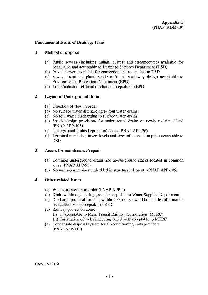
Fundamental Issues of Drainage Plans 1. Method of disposal (a) Public sewers (including nullah, culvert and streamcourse) available for
connection and acceptable to Drainage Services Department (DSD) (b) Private sewers available for connection and acceptable to DSD (c) Sewage treatment plant, septic tank and soakaway design acceptable to
Environmental Protection Department (EPD) (d) Trade/industrial effluent discharge acceptable to EPD 2. Layout of Underground drain (a) Direction of flow in order (b) No surface water discharging to foul water drains (c) No foul water discharging to surface water drains (d) Special design provisions for underground drains on newly reclaimed land
(PNAP APP-103) (e) Underground drains kept out of slopes (PNAP APP-76) (f) Terminal manholes, invert levels and sizes of connection pipes acceptable to
DSD 3. Access for maintenance/repair (a) Common underground drains and above-ground stacks located in common
areas (PNAP APP-93) (b) No water-borne pipes embedded in structural elements (PNAP APP-105) 4. Other related issues (a) Well construction in order (PNAP APP-4) (b) Drain within a gathering ground acceptable to Water Supplies Department (c) Discharge proposal for sites within 200m of seaward boundaries of a marine
fish culture zone acceptable to EPD (d) Railway protection zone:
(i) on acceptable to Mass Transit Railway Corporation (MTRC) (ii) Installation of wells including bored well acceptable to MTRC
(e) Condensate disposal system for air-conditioning units provided (PNAP APP-112) (Rev. 2/2016)
- 1 -
Appendix D (PNAP ADM-19)
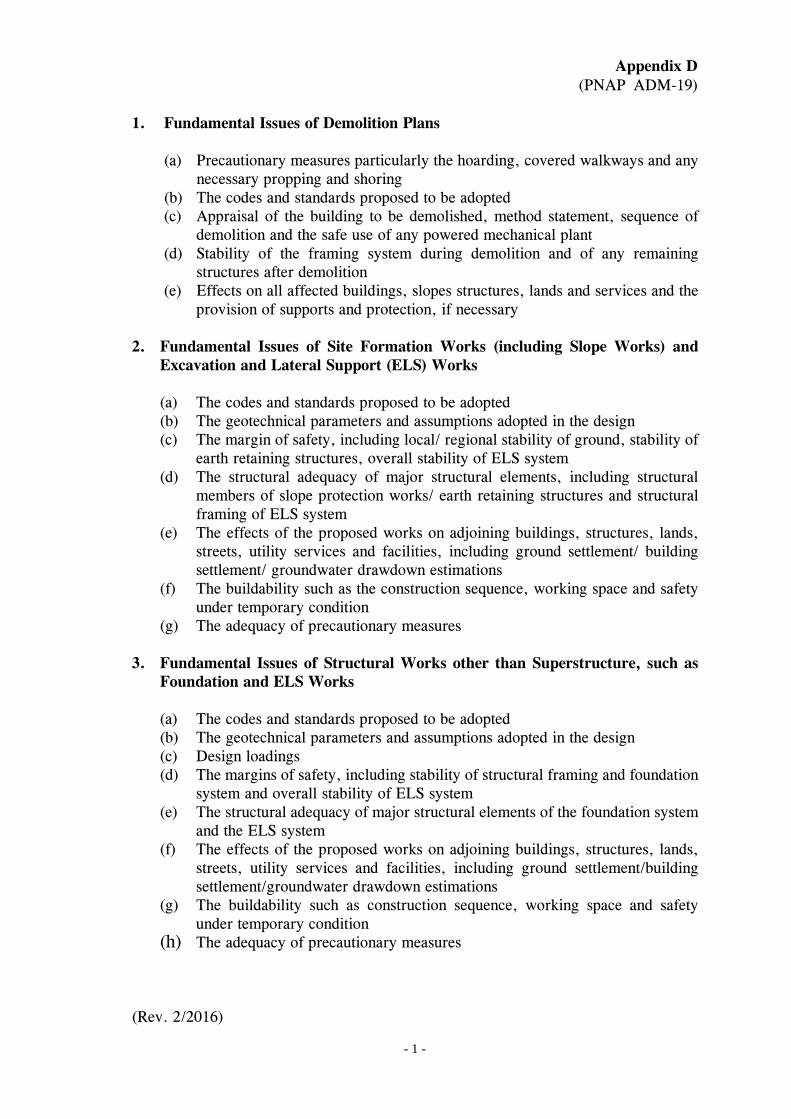
1. Fundamental Issues of Demolition Plans
(a) Precautionary measures particularly the hoarding, covered walkways and any necessary propping and shoring
(b) The codes and standards proposed to be adopted (c) Appraisal of the building to be demolished, method statement, sequence of
demolition and the safe use of any powered mechanical plant (d) Stability of the framing system during demolition and of any remaining
structures after demolition (e) Effects on all affected buildings, slopes structures, lands and services and the
provision of supports and protection, if necessary 2. Fundamental Issues of Site Formation Works (including Slope Works) and
Excavation and Lateral Support (ELS) Works
(a) The codes and standards proposed to be adopted (b) The geotechnical parameters and assumptions adopted in the design (c) The margin of safety, including local/ regional stability of ground, stability of
earth retaining structures, overall stability of ELS system (d) The structural adequacy of major structural elements, including structural
members of slope protection works/ earth retaining structures and structural framing of ELS system
(e) The effects of the proposed works on adjoining buildings, structures, lands, streets, utility services and facilities, including ground settlement/ building settlement/ groundwater drawdown estimations
(f) The buildability such as the construction sequence, working space and safety under temporary condition
(g) The adequacy of precautionary measures 3. Fundamental Issues of Structural Works other than Superstructure, such as
Foundation and ELS Works
(a) The codes and standards proposed to be adopted (b) The geotechnical parameters and assumptions adopted in the design (c) Design loadings (d) The margins of safety, including stability of structural framing and foundation
system and overall stability of ELS system (e) The structural adequacy of major structural elements of the foundation system
and the ELS system (f) The effects of the proposed works on adjoining buildings, structures, lands,
streets, utility services and facilities, including ground settlement/building settlement/groundwater drawdown estimations
(g) The buildability such as construction sequence, working space and safety under temporary condition
(h) The adequacy of precautionary measures (Rev. 2/2016)

Appendix E
(PNAP ADM-19)
Guidelines for Concept Drawings 1 Basic Information in Concept Drawings
(a) Site coverage including accountable, non-accountable and exempted SC
areas (b) GFA including accountable, non-accountable and exempted domestic and
non-domestic GFA (c) Fire safety strategy including MOE, MOA and FRC arrangements (d) Barrier free access including basic provision of access and facilities for
wheelchair-users
2 Sample Drawings Sample concept drawings are available in BD’s website at www.bd.gov.hk for reference.
3 Size A2, A3 or A4 depending on size of development
4 Colour Scheme It is recommended that the colour schemes for designation of different types of SC & GFA and barrier free access in sample concept drawings be adopted.
5 Signs and Indicators It is recommended that the signs and indicators for MOE, MOA and FRC arrangements in the sample concept drawings be adopted.
(Rev. 2/2016)

- 1 -
Appendix F (PNAP ADM-19)
Notes on Submission Drawing Standards in Electronic Format Electronic Submission for Mathematical Calculation of Areas
Introduction The purpose of this supplementary note is to advise on the electronic format and the pre-requisites for checking of area calculations in CAD drawing files electronically. 2. When the requirements set out in the following paragraphs are complied with and clearly shown in the submitted CAD drawing files, diagrammatic breakdowns and details on calculation of the gross floor area, usable floor area, site coverage, plot ratio, refuge floor area and green feature area etc. would not be required to be included in plan submission. For avoidance of doubt, annotation and dimension of the areas concerned are required to be indicated on plans for checking purpose. Samples of the dimensioned plans are in Annex 1 for reference.
3. For area calculations computed electronically, soft copies of the building floor plans containing the area diagram layer(s) are required to facilitate verification of the calculations. For approval purpose, hard copies of the general building plans showing floor area layouts, area diagrams and calculations without breakdowns are required. Information shown in both the soft and hard copies of the plans submitted for approval must be identical to each other. Plans may be rejected if discrepancy between the two is found. The AP should certify on each of the DVD-ROM discs with a permanent marker signifying that information in the electronic drawing files are identical to the submitted hard copies and that all files are prepared under his supervision. The disc should be finalised before submission, i.e. the contents of the disc cannot be further changed. His signature shall be deemed to be his assumption of responsibility for the electronic plans and the calculations.
4. The following minimum requirements in CAD drawing format should be observed and provided for in the area calculations computed electronically. Plans may be rejected on grounds of insufficient information if these requirements are not complied with.

- 2 -
4.1 Format and Software Version
(a) The submitted CAD drawing files should be stored in non-rewritable DVD-ROM discs. Except otherwise agreed by the Building Authority all other electronic submission formats are not acceptable.
(b) CAD drawings using AutoCAD version R14 or later or
MicroStation version SE, J, V8 or later are acceptable. (c) AutoCAD files should be saved in “.dwg” format and
MicroStation files in “.dgn” format only. All other compressed or zipped file formats are not acceptable.
(d) Title blocks completed with drawing number showing revision
legends, site/project title, drawing title etc. should be inserted in every drawing for identification purpose. Each CAD file shall contain one hard copy drawing only. Typical title block sample is attached in Annex 2 for reference.
4.2 Referencing System File Name/Drawing Number Convention (a) Each file shall contain one drawing only, default zoomed to full
drawing extent. (b) All information for approval shall be contained in the same
drawing file. The need to cross-reference or hyper-link with another CAD file to enable verification of the area calculations in the DVD-ROM is not acceptable except in situation covered in (c) below.
(c) In situation where the layering number and the system are limited
due to software constraint, limited referencing system might be used provided that all information and model files which compose the final drawings are clearly visible and intact when files are open in the computer. A clear and systematic path trial in hard copy format highlighting the list of file(s) for area checking purpose should be provided to facilitate the verification exercise. All drawing files and model files are to put into the same folder to ensure coherent path recognition. Cross-referencing and hyper-linking within folder should be kept to the minimum.
(d) Naming and numbering of drawing files in the hard copy should
be identical to those in the submitted soft copy.

- 3 -
(e) A completed hard and soft copy of the drawing index listing all file names, drawing numbers with brief description on location and contents of the submitted drawings shall be provided. Drawings under different revision must carry a revision letter (e.g. A to Z) for identification purpose. For large and complicated project involving numerous drawing versions/amendments, a revision legend should also be provided as well.
e.g. B-01_ A. DWG
Drawing No. Rev. A
4.3 Layering Organization (a) CAD drawing files including floor plans, tables and calculations etc.
shall contain all information identical to the hard copy. Each file shall accommodate different elements such as floor layout plans, usable floor area, gross floor area and dimension etc. into the relevant layers. The “layering” drafting technique isolates elements of a drawing and places them into separate layers for easy reference and manipulation. The same principle applies to “level” in MicroStation files.
(b) To facilitate checking of the area calculations, general building plans
shall contain GFA and other areas diagram layer(s) for verification and calculations. To reconcile the requirements of other government departs and to adopt the rules under CAD Standards for Works Projects (CSWP) of Environment, Transport and Works Bureau, AP shall name the relevant layers in a format specified below :
Layer Name Convention Diagram A: Rules of Layer Name Convention of CSWP (abstracted)
ARC 082 4 0
Field 3 - Addition/Deduction Type Field 2 - Building Plan Area Type (Sub-class) Field 2 - CSWP Element Code assigned for
Building Plan Area Calculation (Class) Field 1 - Agent Responsible Code (ARC) e.g. ADA Field Description Length/Type Coding
1 Agent Responsible Code 3 (alphanumeric) See www.etwb.gov.hk/cswp2 CSWP Element Code
assigned for Building Plan Area Calculation (Class)
3 (numeric) a) 082 for BD’s area calculation, b) 086 for LandsD’s area calculation
Building Plan Area Type (Sub-class)
1 (numeric) See Diagram B
3 Addition/Deduction Type 1 (alphanumeric) See Diagram C
- 4 -
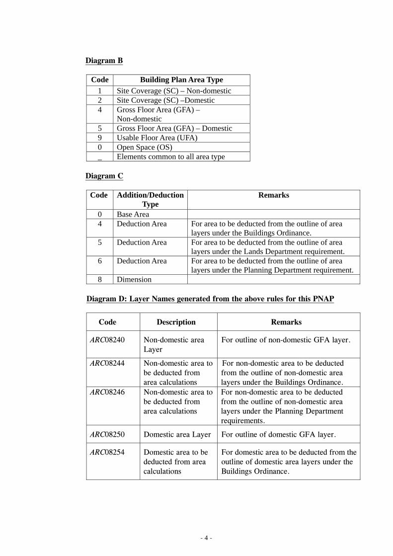
Diagram B
Code Building Plan Area Type
1 Site Coverage (SC) – Non-domestic 2 Site Coverage (SC) –Domestic 4 Gross Floor Area (GFA) –
Non-domestic 5 Gross Floor Area (GFA) – Domestic 9 Usable Floor Area (UFA) 0 Open Space (OS) _ Elements common to all area type
Diagram C
Code Addition/Deduction Type
Remarks
0 Base Area 4 Deduction Area For area to be deducted from the outline of area
layers under the Buildings Ordinance. 5 Deduction Area For area to be deducted from the outline of area
layers under the Lands Department requirement. 6 Deduction Area For area to be deducted from the outline of area
layers under the Planning Department requirement. 8 Dimension
Diagram D: Layer Names generated from the above rules for this PNAP
Code Description Remarks
ARC08240 Non-domestic area Layer
For outline of non-domestic GFA layer.
ARC08244 Non-domestic area to be deducted from area calculations
For non-domestic area to be deducted from the outline of non-domestic area layers under the Buildings Ordinance.
ARC08246 Non-domestic area to be deducted from area calculations
For non-domestic area to be deducted from the outline of non-domestic area layers under the Planning Department requirements.
ARC08250 Domestic area Layer For outline of domestic GFA layer.
ARC08254 Domestic area to be deducted from area calculations
For domestic area to be deducted from the outline of domestic area layers under the Buildings Ordinance.

- 5 -
ARC08256 Domestic area to be deducted from area calculations
For domestic area to be deducted from the outline of domestic area layers under the Planning Department requirements.
ARC082_8 Dimension layers All dimensions for the floor layout plans are automatically generated from the computer software (not to be manually inserted by text input construction)
ARC08210 Area for non-domestic site coverage calculations
For outline of non-domestic site coverage layer.
ARC08214 Non-domestic site coverage deducted from calculations
Deduction complying with requirements of the Buildings Department.
ARC08216 Non-domestic site coverage deducted from calculations
Deduction complying with requirements of the Planning Department.
ARC08220 Area for domestic site coverage calculations
For outline of domestic site coverage layer.
ARC08224 Domestic site coverage deducted from calculations
Deduction complying with requirements of the Buildings Department.
ARC08226 Domestic site coverage deducted from calculations
Deduction complying with requirements of the Planning Department.
ARC08200 Area for open space calculations
For outline of open space layer.
ARC08204 Area to be deducted from open space calculations
For area to be deducted from outline of the open space under the Buildings Ordinance.
ARC08290 Area for usable floor area calculations
For outline of usable floor area layer.
ARC08294 Area to be deducted from the usable floor area calculations
For area to be deducted from outline of the usable floor area under the Buildings Ordinance.
(c) The layer names required by LandsD are not listed in this
PNAP and AP should make reference to the Practice Note issued by LandsD. AP should also refer to CSWP of Environment, Transport and Works Bureau (at www.etwb.gov.hk/cswp) for other layer name convention.
(d) Layering organization of the file(s) in hard copy format shall
be submitted. If more layering description is required in the submitted general building plans, AP could lengthen the above list with additional input along similarly constructed methodology. All layering organizations must be clearly shown.

4.
Layer (e)
.4 Prese
Draw
(a)
Draw (b)
Polyli (c)
Dime (d)
Decim (e)
Sugge (f)
r contents
CAD finformaapprovalayers. like whrequire
entation Sty
wing Scale
CAD drunit = 1mm unit
wing Object
The poCoordinnot be g
ine
All line shall beMicroSt
ension
All dimautomatText ficonstrucacceptab
mal places o
All arearespecti
ested Text F
Text stysuggesterecomm“Engine
file for the ation that haal, includin Elementshere approd should no
yle
rawings sho1mm or met.
within area
osition of nation 0,0 grouped or
drawings ine in closed tation files)
mensions tically by thigures or cted for cable.
of areas an
as and volumvely and ro
Font
yle is not ed. Comm
mended foreering” font
- 6 -
floor planave to be shng, inter als such as ligoval from ot be shown
ould be draetre) with pr
a diagram
the drawiand drawin blocked.
ntended for polyline d.
should behe softwarefigures m
alculation p
nd volumes
mes shouldounded up to
compulsormon type r use in t could be a
n shall conhown on thelia, the areghting, elect
the Buildin in the subm
awn in truerecision rou
ing shall ng objects
r area calculdiagram (or
e true de and laid inmanually inpurpose in
d be presento 3 decimal
ry. Convensuch as
the text. adopted.
tain all elee drawings tea and the tric appliancing Authormitted draw
e size (i.e. unded up to
be close in area dia
lations in ar in comple
imensions n the specifnserted, amthe CAD
ted in m2 anl places.
ntional text“Romans” For Mi
ements andto facilitate dimension
nces and therity is notwings.
1 drawing the nearest
to Worldagram shall
rea layer(s)ex shape in
generatedfied layers.mended orfile is not
nd m3 units
t fonts are” font isicroStation,
n
n
t

- 7 -
Review 5. These guidelines will be refined taking into the experience gained. Suggestions to facilitate and/or to improve the electronic vetting procedures are always welcomed.
(Rev. 2/2016)

Annex 1
Samples for Dimensioned and Annotated GFA Diagrams The following part diagrams shown with dimensions and annotations are for reference only. They are intended to illustrate the minimum information required to facilitate electronic verification of the area calculations more effectively. Illustrations shown are by no means exhaustive.
Sample 1 Rectangular shape GFA diagram
Sample 2 GFA diagram with curve(s) and annotations
-1-

(Rev. 2/2016) - 2 -
Sample 3 GFA diagram (part) with dimension and annotation
Sample 4 GFA diagram (part) with grid line and dimension.
Sample 5 Overview of a sample GFA diagram with calculations

1 * Information box shown in bold letter is compulsory for BD submission. (Rev.2/2016)
Annex 2 Sample Title Panel
Original Drawing No. (if any)
AUTH
REVISIONS INITIAL AND DESIGNATION
NO. DESCRIPTION AND DATE DWN CKD
NAME AND DESIGNATION
AUTHORIZED
CHECKED
DRAWN
DATE INITIAL
PROJECT
DRAWING TITLE
SCALE
DRAWING NO
SOURCE
Revision Column
Site/Project Title
Drawing Title
Scale
Drawing Number (with revision)
Company Logo (if any)
Officers Concern
AP/RSE/RGE’s signature/and stamp chop
90mm(W)x150mm(H) space for BD’s approval stamp/ certification of copies of approved plans (PNAP ADM-10 App A)
BD’s OFFICIAL USE

- 1 -
Appendix G (PNAP ADM-19)
List of Minor Amendments Not Qualified for Deferring Submission
1. For Building and Building (A&A), a minor amendment: (a) resulting in a major revision or localised major revision as per criteria
specified in PNAP APP-55; (b) having material effect on the fundamental issues; (c) involving concern on stability/deformation of slopes, retaining walls,
adjoining land and buildings; (d) involving an application for exemption or modification of the BO and its
subsidiary regulations; (e) not in compliance with the relevant Outline Zoning Plan or deviating from a
scheme approved by the Town Planning Board; or
(f) involving works outside the lot boundary.
2. For superstructure and superstructure (A&A), a minor amendment: affecting the overall structural stability of the building. 3. For drainage and drainage (A&A), a minor amendment: (a) encompassing the revision of drainage layout as a result of a major revision
of the building proposal;
(b) involving the change of disposal system or connections to public sewers;
(c) concerning stability/deformation of slopes, retaining walls, adjoining land and buildings;
(d) involving an application for exemption or modification of the BO and its subsidiary regulations;
(e) involving excavations deeper than 3m; or
(f) entailing works outside the lot boundary.
(Rev. 2/2016)

Appendix H (PNAP ADM-19)
Request for Fast Track Processing of Plans
of Alteration and Addition (A&A) Works and Certificate of Preparation of Plans To the Building Authority, In accordance with paragraph 24 of PNAP ADM-19, I hereby request for fast track processing of the plans submitted for the proposed A & A works to be carried out at . 2. I confirm that the A & A works as shown on the enclosed drawings (dwg. no. ___________ _ to ___________ __) do not involve the structure of the building and do not involve changes to the latest approved plans of the affected areas in the following aspects :
Density - site parameter, plot ratio, site coverage Fire safety - means of access, means of escape in case of fire, fire
resistance, compartmentation Health and environment - lighting, ventilation, open space Fundamental issues required under allied legislation - fire safety, OZP,
access for persons with a disability, airport height restrictions, railway route protection
3. I also confirm that the A & A works as shown on the enclosed drawings (dwg. no. ________ to ) involve changes to the latest approved plans of the affected areas in the following aspects :
Fire safety - means of access, means of escape in case of fire, fire resistance, compartmentation
Health and environment - lighting, ventilation, open space Minor changes to structural elements of the building
and that such changes as shown on the said drawings comply with the provisions of the Buildings Ordinance. 4. A Form BA 8A applying for your consent to the commencement and carrying out of the A & A works mentioned in paragraph 1 above is enclosed.
Date Signature of Authorized Person (Name in full)
Signature of Registered Structural Engineer * delete whichever is inapplicable (Name in full) (Rev. 2/2016)
Appendix I (PNAP ADM-19)
Fast Track Processing of Proposal
for Two-Storey Warehouse
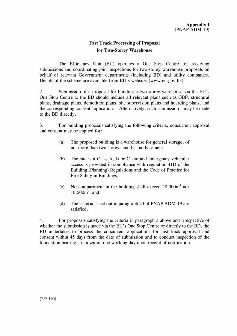
The Efficiency Unit (EU) operates a One Stop Centre for receiving
submissions and coordinating joint inspections for two-storey warehouse proposals on behalf of relevant Government departments (including BD) and utility companies. Details of the scheme are available from EU's website: (www.eu.gov.hk). 2. Submission of a proposal for building a two-storey warehouse via the EU’s One Stop Centre to the BD should include all relevant plans such as GBP, structural plans, drainage plans, demolition plans, site supervision plans and hoarding plans, and the corresponding consent application. Alternatively, such submission may be made to the BD directly. 3. For building proposals satisfying the following criteria, concurrent approval and consent may be applied for:
(a) The proposed building is a warehouse for general storage, of not more than two storeys and has no basement;
(b) The site is a Class A, B or C site and emergency vehicular
access is provided in compliance with regulation 41D of the Building (Planning) Regulations and the Code of Practice for Fire Safety in Buildings;
(c) No compartment in the building shall exceed 28,000m3 nor
10,500m2; and (d) The criteria as set out in paragraph 23 of PNAP ADM-19 are
satisfied. 4. For proposals satisfying the criteria in paragraph 3 above and irrespective of whether the submission is made via the EU’s One Stop Centre or directly to the BD, the BD undertakes to process the concurrent applications for fast track approval and consent within 45 days from the date of submission and to conduct inspection of the foundation bearing strata within one working day upon receipt of notification. (2/2016)