appendix a. on the drawing of crystal … the drawing of crystal figures ... make clear the...
TRANSCRIPT
APPENDIX A.
ON THE DRAWING OF CRYSTAL FIGURES
IN the representation of c stals by figures it is customary to draw their ed es as if they were projected upon some gfinite plane. Two sorts of projection are use8; the ah- graphic in which the lines of projection fell a t right angles and the clinographic where they fall a t oblique angles upon the plane of projection. The second of these projections is the more important, and must be tr2atcd here in some detail. Two points are to be noted in regard to it. In the first place, in the drawings of crystals the point of view is su posed to be a t an infinite distance, and i t follows from this that all lines which are paralgl on the crystal appear paraUel in the drawing.
In the second place, in all ordinary cases, it is the complete ideal crystal which is repre- sented, that is, the crystal with its full geometrical symmetry as explained on pp. 10 to 13 (cf. note on p. 13).
In general, drawings of crystals are made, either bv constructing the figure upon a projection of its crystal axes, using the intercepts of t,he different faces upon the axes in order to determine the directions of the edges or by constructing the figure from the gnomonic (or stereographic) projection of the crystal forms. Both of these methods have their advantages and disadvantages. By drawing the crystal figure by the aid of a projection of its crystal axes the symmetry of the crystal and the relations of its faces to the axes are emphasized. In many cases, however, drawing from a projection of the poles of the crystal faces is simpler and takes less time. The student should be able to use both methods and consequently both are described below.
DRAWING OF CRYSTALS UPON PROJECTIONS OF THEIR CRYSTAL AXES
PROJECTION OF THE AXES
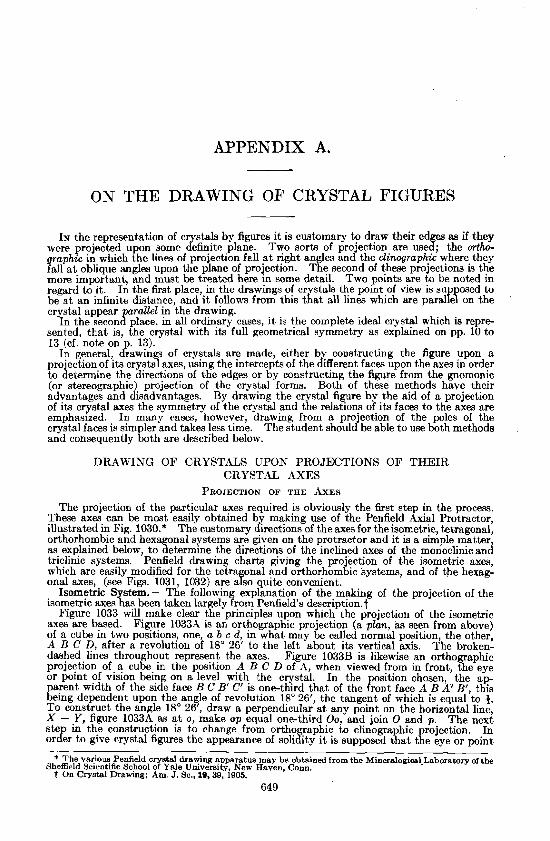
The projection of the particular axes required is obviously the first step in the process. These axes can be most easily obtained by making use of the Penfield Axial Protractor, illustrated in Fig. 1030.* The customary directions of the axes for the isometric, tetragonal, orthorhombic and hexagonal systems are given on the protractor and it is a simple matter, as explained below, to determine the directions of the inclined axes of the monoclinic and triclinic systems. Penfield drawing charts giving the projection of the isometric axes, which are easily modified for the tetragonal and orthorhombic systems, and of the hexag- onal axes, (see Figs. 1031, 1032) are also quite convenient.
Isometric System.- The following explanation of the making of the projection of the isometric axes has been taken largely from Penfield's descripti0n.t
Figure 1033 will make clear the principles upon which the projection of the isometric axes are based. Figure 1033h is an orthographic projection (a plan, as seen from above) of a cube in two positions, one, a b c d, in what may be called normal position, the other, A B C D, after a revolution of 18" 26' to the left about its vertical axis. The broken- dashed lines throughout represent the axes. Figure 1033B is likewise an orthographic projection of a cube in the position A B C D of 11, when viewed from in front, the eye or point of vision being on a level with the crystal. In the chosen, the ap-
arent width of the side face B C B' C' is one-third that of the ront face A B A' B', this Eehg dependent upon the angle of revolution 18" 26', the tangent of which is equal to g. To construct the angle 18" 26', draw a perpendicular a t any point on the horizontal line, X - Y, figure 1033A as a t o , make o p equal one-third 0 0 , and join 0 and p. The next ste in the construction is to change from orthographic to clinographic projection. In or& to give crystal figures the appearance of solidity it is supposed that the eye or point
* The various Penfield cry~tal drawing apparatus may be obtained from the Mineralogicsl.Laboratory of the Sheffield Scientific School of Yale University. New Haven. Conn.
t On Crystal Drawmg; Am. J. Sc., 19.39, 1905.
649

APPENDIX A
Protractor for plotting crystallographic axes; one-third natural size (after Penfield)
1031 1032
Scheme of the engraved exes of the i~omet~ric and hexagonal systems, one-sixth natural size (after Penfield)
APPENDIX A 65 1
of vision is raised, so thatbne looks down a t an angle upon the crystal; thus, in the case under consideration, figure 1033C, the top face of the cube comes into view. The position of the crystal, however, is not chmged, and the plane upon which the project,ion i made remains vertical. From A it may be seen that the
ositive ends of the axes al and Q are forward of the 1033 Erie XY, the +stances alz and Q y being as 3 : 1. In . D B it must he ~magined, and by the aid of a model it may easily be seen, that the extremities of these same sxes are to the front of an imagmary vertical plane (the projection of X Y above) assing through the center of the crystal, the distance %eing the same as al z and Q y of the plan. In D the distance ax is drawn the same length as alz of the plan, and the amount to A which it is supposed that the eye is raised, indicated by the mow, is such that a, instead of being projected horizontally to x, is projected a t an inclination of 9" A 28' from the horizontal to w, the distance zw being one- sixth of ax; hence the angle 9" 28' is such that its tangent is +. Looking down upon a solid a t an angle, and still making the projection on a vertical plane, may A
be designated as clinographic projection; accordingly, to plot the axes of a cube in clinographic projection in conformity with figures A, B and D draw the horizontal construction line hk, figure C, and cross it B by four perpendiculars in vertical alignment with the points a,, - al and m, - Q of figures A and B. Then determine the extremities of the first, al, - a' axis by laying off distances equal to xw of fi ure D, or one- sixth al x of figure A, locating $em befow ~d above .A' the horizontal hne hk. The line a,, - al 1s thus the projection of the first, or frontcto-back axis. In like mznner determine the extremities of the second axis, a2, - Q, by laying off distances equal to one-third zw of figure D, or one-sixth ~y of figure A, plotted below and above the line hk. The line Q, - az is thus the c projection of the second, or right-to-left axis. It is important to keep in mind that in clinographic projec- tion there is no foreshortening of vertical distances. In figure C the axis 02, - a2 is somewhat, and a,, - a, much foreshortened, yet both represent axes of the same length as the vertical, a ~ , - aJ.
I t is wholly a matter of choice that the angle of revolution shown in figure 1033A is 18" 26', and that the eye is raised so aa to look down upon a crystal a t Development of the axes of the an angle of 9" 28' from the horizontal, as indicated by isometric system in orthographic figure 1033D. Also it is evident that these angles may and clinographic ' projection be varied to suit any special requirement. AS a mat- (after Penfield) ter of fact, however, the angles 18" 26' and 9" 28' have been well chosen and are established by long usage, and practically all the figures in din- ogra~hic projection, found in modern treatises on crystallography and mineralogy, have been drawn in accordance with them.
Tetragonal and Orthorhombic Systems. - The projection of tetragonal and orthor- hombic axes can be easily obtained from the isometric axes by modifying the lengths of the various axes to conform to the axial ratio of the desired crystal. For instance with zircon the vertical asis has a relative length of c = 0.64 in respect to the equal lengths of the hori- zontal axes. By taking 0.64 of the unit length of the vertical axis of the isometric projec- tion the crystal axes for a zircon figureare obtained. The Penfield axial charts all give decimal parts of the unit length of the isometric vertical axis, so that any proportion of this length can be found a t once. In the orthorhombic system the lengths of both the a and c axes must be modified. The desired point upon the c axis can be obtained as de- scribed above. In the case of the a axis the required oint can be found by some simple method of construction. If, as is the case in the ~enfie?d charts, a plan of the unforeshort- ened horizontal axes is given in a top view, the desired length can be hid off directly upon

652 APPENDIX A
the a axis in this orthographic projection by means of the decim'al scale and then projected vertically down upon its clinographic projection. Or the proper distance can be laid off on the vertical axis and then by means of a line drawn from this point parallel to a line joining the extremities of the c and a axes of the isometric projection the proper proportional
part of the a axis can be determined by intersection. 1034 Hexagonal System. For projecting the hexagonal axes a3 exactly the same principles may be made use of as were
employed in the construction of the isometric axes. Figure 1034A is an orthographic projection, a. plan, of a hexagonal prism in two positions, one of them, al, az, etc., after a revolution of 18" 26' from what may be called normal posi- tion. In figure 1034B the extremities of the llorizontal axes of A have been projected down upon the horizontal construc-
a2 tion line hk, and al, ar and - a3 which are forward of the line XY in A are located below the line hk in the clin- ographic projection, the distances from hk being one-sixth of alx, a21~ and - a3z of A. Figure 1034C is a scheme for getting the distances which the extremities of the axes are dropped. The vertical axis in 1034B has been given the same length as the axes of the plan.
Monoclinic System. - In the case of the monoclinic axes t.he inclination and length of thc a axis must be determined in each case. The axial chart, Fig. 1030, can
2 he most conveniently used for this purpose. The ellipse in the figure, lettered A, C, - A, - C gives the trace of t.he ends of the a and c axes as they are revolved in the A -- C plane. To find, therefore, the inclination of the a, axis it is only necessary to lay off the angle by means of the graduation given on this ellipse. The unit length of the a axis may be determined in various ways. Thc plan of thc axes given a t the top of the chart may be used for this
Develo merit of the axes of purpose. Fig. 1035 will illustrate the method of procedure the Kexagonal System in as applied in the case of orthoclase, where /3 = 84' and 0 r t h 0.g r a p h i c and c h - a = 0.66. The foreshortened length of the a axis is de- ogra hlc prolection (after termined as indicatcd and then this length can he projected ~ e n g l d ) vertically downward upon the inclined a axis, the direction
of which has been previously determined as described above. Triclinic S stem. - In the construction of triclinic axes the inclination of the a axis
and its lengtK are determined in exactly the same manner as described in the preceding p a r a r p h in the case of the monoalinic system. The direct,ion of the axls ia determined as fo ows. The vertical plane of the b and c axes is revolved about the c axis through such an ang1e.a~ 10Z6 will conform to the angle between the pmaco~ds 100 and 010. Care must be taken to note whether this plane is to be revolved toward the front or toward the back. If the angle between the normals to 100 and 010 is greater than 90" the right hand end of this plane is to be revolvcd toward the front. Figure 1036, which is a simplified or ti on of the axial chart, shows the necessary construction In order to obtain the direction of the b axls in the case of rhodonite in which 100 A 010 = 94" 26' and a = 103' 18'. The plane of the b-c axes wlH pa58 through the point p which is 94" 26' from -a. TO lomte the oint b', whlch is the po~nt. where the b a x i ~ roul$ emerge from the sphcrc, draw through the polnt p two or more chords from oink where the vertical ellipses of the chart cross t i e horizontal eUipse, as lines a-p. -a-p. b-p, in figure 1036. Then from pointa on these same vertical elh ses which are 13" 18' below the horizontal plane 8 a w *
chorb perallel to the first series as x-x',, y-y', 2-2'. The poh t where these thrb chords meet determines the poaitlon of b' and a line from this point drawn through the center of the

APPENDIX A 653
chart determines the direction of the b axis, since it lies in the proper vertical plane and makes the angle a, 103' 18', with the c axis. The foreshortened len@h of the b axis can be determined by the use of the orthographic projection of the a and b axes a t the top of the chart in exactly the same manner as described under the monoclinic system and the point thus determined may be projected vertically downward upon the llne of the b axis of the clinographic projection as already determined. It must be 1036 remembered, however, that the position of the b axis in the ortho- graphic projection must conform to the position of the plane of the b and c axes or in the case of rhodonite have its right hand end a t an angle of 94" 26' with the negative end of the projection of the a axis. a
Drawing of Crystal Figures by 2 Aid of Projections of their > z' Axes. - In order to determine in the drawing the direction of any ' edge between two crystal faces it is necessary to establish two points, both of which shall be common to these t,wo faces. A line connecting two such points will obviously have the desired direction. The posi- tions of these points is commonly established by use of the linear or Quendstedt projec- tion as explained in the following paragraphs, which have been taken almost verbatim from Penfield's description of the process.
The principle upon which the linear projection is based is very simple: Every face of a crystal (shifted if necessary, 'but without change of direction) i s made to intersect the vertical axis at U N I T Y , and then its intersection with the horizontal plane, or the plane of the a and b axis i s indicated by a line. For instance if a given face has the indices 111 it is clear that its linear projection would be a line passing through l a and lb, since the face under these conditions will also pass through lc. If, however, the indices of the face are 112 it will
only pass through 1 /2 c when it passes through laand lb. In
1037 order to fulfill, therefore, the requirements of the linear projec- tion that the plane should pass through l c the indices must be multiplied by two and then under these conditions the line in which the plane intercepts the horizontal plane, or in other words the linear projection of the face, will pass through 2a and 2b. In the case of a prism face with the indices 110, its linear projection will be a line having the same direction as a line join- ing l a and lb but passing through the point of intersection of these axes, since a vertical plane such as a prism can only pass through Ic when it also includes the c axis and so must have its linear projection pass through the point of intersection of the three axes.
When it is desired to find the direction of an edge made by the meeting of any two faces, the lines representing the linear projec- tion of the faces are first dmwn, and the point where they inter- sect is noted. Thus a point common to both faces is deter- mined, which is located in the plane of the a and b axes. A second point common to the two faces is unity on the vertical axis, and a line from this point to where the lines of the linear projection intersect gives the desired direction.
A simple illustr&tion, chosen from the orthorhombic system will serve to show how the linear projection may be employed in drawing. The example is a combination of barite, such as is shown in figure 1037. The axial ratio of barite is as follows:
a : b : c = 0.8152 : 1 : 1.3136 The forms shown in the figure and the symbols are, base c (001), prism m (110), brachydome o (011) and macrodome d (102).
Figure 1038 represents the deta~ls of construction of the orthographic and clinographic projections shown in figure 1037.
On the orthographic axes the axial lengths a and b are located, the vertical axis c being

654 APPENDIX A
foreshortened to a point a t the center. On the clinographic axes, centered a t 0, the ends of the axes a and b are located by dropping perpendiculars from corresponding points above, and the length of the vertical axis 1.316 is laid off above and below 0 by means of the scale of decimal arts, a t points marked 1 and - 1 in the figure. The lines of the linear projection neefed for the two sets of axes are as foIlows: For the brachydome o, 011, the lines xz and x'zf, through b parallel to the a axis : For the macrodome d, 102
1038
(2a : oo b : c ) , the lines x and x'y', through 2a parallel to the b axis: The prism m (110) ie parallel to the verticaf axis, hence in order that such a plane shall satisfy the con- ditions of the linear rojec'tion and pass through unity o n the vertical axis, it must be considered its ahiftea (without change of direction) until i t passes through the center: Its linear rojection therefore is re resented by the lmes yz and y'z', parallel to the directions ?a to I b on the two seb of axes. Since a linear rojection is made on the plane of the a and b BW, the intersection of any face with t i e base (001) has the same direction as the line repmxmting its linear projection. It is well to note that the inter- sections x, y and z and x', y' and x' are in vertical alignment with one another.
Concerning the drawing of w e 1038, i t is a simple matter to proportion the general outline of the barite c std in orthographic projection. The direction of the ed between d, 102, and 0 , 011, is gtemnhd by 6ndh the point x, where the !nes of t h e g e a r pro- jection of d and o intersect, and drawing t%e edge arallel to the direction from z to the , center e. The intersection of the rism m, 110, wit! d and o,is a straight line, pa rd+ to the direction la to lb or to z. 'lPo construct the clmo-rctph~c figure, a t some convement point beneath the axes t f e horizontal middle edges of the crystal .ma be drawn parallel to the o and b ma, their h g t h and i n t e ~ ~ t ~ o n s being deternuns8 by carryine~ down perpendiculars fmm the or tho~aphic pmjectlon above. The intersection between d.

APPENDIX A 655
102, and o, 011, is determined by finding the point x' of the linear ~rojection and drawing the edge parallel to the direction from x' to 1 (unity) on the vertical axis, while the corre- spondin direction below is parallel to the direction x' to - 1. The size of the prism m, 110, a n f i t s Intersections with d and o may all be determined by carryin down perpendicu- lars from the orthographic projection above, but it is well to controf the directions by means of the linear projection: The edges between m, 110, and d, 102; and m, 110, and 0, 011, are parallel respectively to the directions y' to 1 and z' to 1. Having completed a figure, a copy free from construction lines may be had by placing the drawin over a clean sheet of paper and puncturing the intersections of all edgm with a needfepoint: An accurate tracing may then be made on the lower paper.
Should it happen that the linear projection made on the plane of the a and b axes gives intersections far removed from the center of the figure, a linear projection may be made on the clinographic axes either on the plane of the a and c or b and c axes, supposing that the faces pms, respectively, through unity on the b or the a axes.
Importance of an Orthographic in connection with a Clino aphic Projection. - Many students, on commencing the study of crystallography, fail to %rive the benefit they should from the figures given in textrbooks. Generally clinographic projections are given almost exclus- ively, with perhaps occasional basal or ortho- graphic projections, and beginners find i t hard to reconcile many of the figures with the ap- pearance of the models and crystals which they are intended to represent. For example, only the clinographic projection of barite, f$g 1037, i t takes considerable training and knowledge of the projection employed to gain from the figure a correct idea of the proportions of the cryshl
by comparing figures 1037 and 1039, which rep- which it actually represents. This may be shown
resent the same crystal, drawn one with the a, the other with the b axis to the front. I t is seen from figure 1039 that the crystal is far longer in the direction bf the a axis than one would imagine from inspection of only the clinographic projection of figure 1037. The
front or a axis is much foreshortened in clinographic projection, consequently by the use of only this one kind of pro'ection there is a two-fold tendency to err; on the one hand, in drawing, one is inclined to represent thoee edges running parallel to the a axis by lines whlch are considerably too long, while, on the other hand, in studying figures there is a tendency to regard them as representing crystals which are too much compressed in the direction of the a axis. By using orthographic m con- nection with clinographic projections these tendencies are over- come. Having in mind the proportions of a certain crystal, or having a t hand a model, it is easy to construct an oftho aphic projection in which the a and b axes are represented w i t f their true proportions; then the construction of a clino~raphic projec- tion of correct proportions follows as a comparatively simple matter. Without an orthographic projection it would have been a difficult task to have constructed the clinographic projection of figure 1039 wth the proportions of the intercepts upon the a and b axes the same as in figure 1037, while with the ortho- graphic projection orientated as in figure 1039 i t was an easy matter. A combination of the two projections is preferable in many cases and from the two figures a proper conception of the development of the crystal may be had.
Drawing of Twin Crystals. - The axial protractor furnishes a convenient means for plotting the axes of twin crystals. The
m actual operation will differ with different pfoblems but the en era1 methods are the same. The two examples given will ifius: trate these methods.
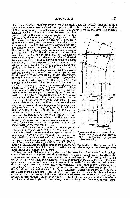
(1). To plot the azes for the staurolite twin shown i n Fig. 1040. In this-case the twinning plane is parallel to the crystal face 232 which has the axial intercepts of -3/2a, b, -3/2c.
For staurolite, a : b : c = 0.473 : 1 : 0.683, while the @ and p angles of the twinning plane
/ 656 APPENDIX A
are, 6 = 010 A 230 = 54" 37' and p = O O i A 232 = 60" 31'. To insure accuracy in p lo t ting, the full lengths of the axes of the protractor have been re arded as unity. The first step is to locate on the clinopaphic projection the position OF the twinning plane, 239.
1041 This is shown in Fig. 1041 as the triangle from - 3/2a to b to - 3/2c. The next step is to find the position of the twinning axis which will be normal to this plane. The coordinates of this twinning axls are given
37' by t,he 6 and P angles quoted above. The point p which is 54" 37' back from the pole to 010 or b marks the place where the normal to the prism face 230 would %merge from the sphere. The normal to 232, which is fhe twinning axis will emerge on the merichan that runs through the point p and a t such a distance below i t that it will m.ake tthe angle 60" 31' with the negative end of the c axis. Chords are drawn to p from the points where the a and b axes meet the equator of the 5 here and then chords parallel to these are $awn from the points r, y and e which are in each case 60" 31' from the point where the
-LC negative end of the c axis cuts the spherical surface. The eomfnon meeting
these chords 6 marks the place where the twinning axis pierces t h e rphericaC$tfa;! The next step is to determine the point 1 a t which the twinning axis cuts the twinning plane. The line OPp is by construction at right angles to the line connecting -3,"2a and lb. Therefore s vertical plane which is normal to the twmning lane would intersect that plane in the line connecting-3/2c and P. The tw~nning ax~s 8~ would lie in this plane also. Consequently the po~nt 1, wherc 01' and -3/2c-P intersect would lie both on the twinning axis and in the twinning lane. In order to make the metRod of construction
1042
clearer Fig. 1042 is given. Here the twinning axis is repeated from Fig. 1041. The twin posi- tion of the crystal is to be found by revolving i t from its normal position through an arc of If@", using the twinning axis as the axis of revolution. This will turn the twinning plane about upon the point 1 as a pivot and so transposs the points -3/2a, b and 3 / 2 c to points equidistant from i t in an opposite position. By drawing lines through t and laying off equal distances beyond that point the new points -3/2A, B and -3/2C will be obtained. These pomts lie upon the three axes in their twin position and so determine their directions.
The plotting of the twin axes in the top view follows similar methods. In order to make the construction learer a separate
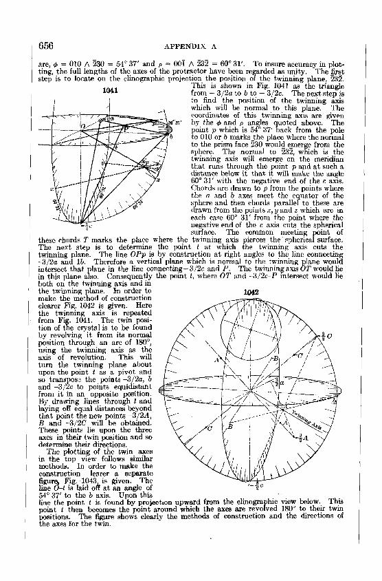
Fig. 1043, is given. The k%-t is laid off a t an angle of 54" 37' to the b axis. Upon this line the point t is found by projection upward from the clinogra hic view below. This po+t ! then becomes the point around which the axea are revoked 18U0 to. theF twyl ~os~tions. The f i w e shows clearlv the methods of construct~on and the hrect~ons of
1 the axes for the &in.
APPENDIX A 657
Upon the twin axes found in this way the portion of the crystal in twin position is drawn in exactly the same manner as if it was in the normal position.
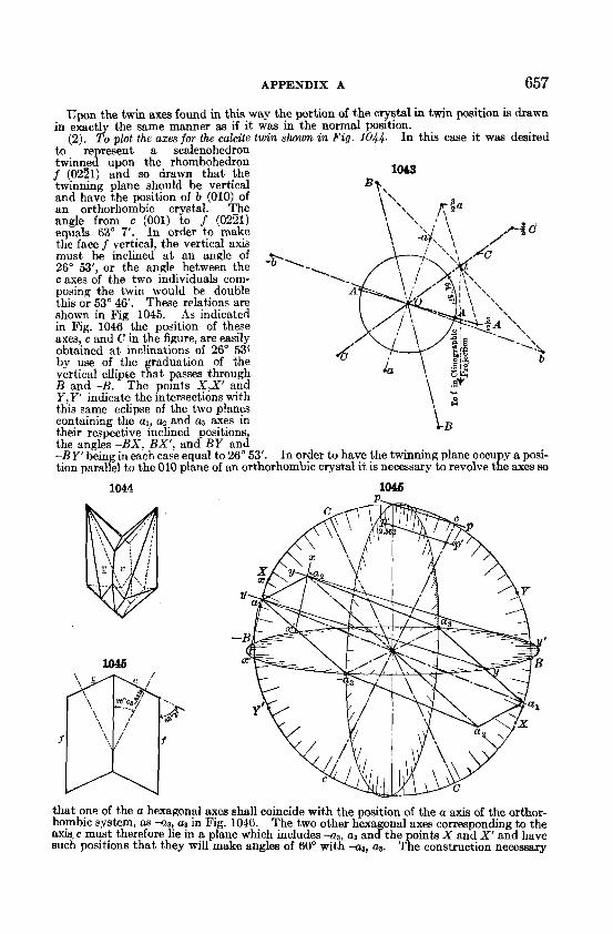
(2). To plot the axes for the calcite twin shown in Fig. 1044. In thk case i t was desired to represent a scalenohedron twinned upon the rhombohedron f (0221) and so drawn that the 1043 twinning plane should be vertical and have the position of b (010) of an orthorhombic crystal. The angle from c (001) to f (0221) equals 63" 7'. In order to make the face f vertical, the vertical axis must be inclined a t an angle of 26" 53', or the angle between the -p'l-
c axes of the two individuals com- posing the twin would be double this or 53" 46'. These relations are ~hown in Fig 1045. As indicated in Fig. 1046 the position of these axes, c and C in the figure, are easily obtained a t inclinations of 26" 53{ by use of the graduation of the b vertical ellipse that passes through B and -B. The points X,X' and Y.Y1 indicate the intersections with this same eclipse of the two planes containing the al , a2 and a3 axes in their respective inclined positions LB the angles -BX, BX', and BY and -BY' being in each case equal to 26" 53'. In order to have the twinning plane occu y a posi- tion parallel to the 010 plane of an orthorhombic crystal i t is necessary to revolve tk axes so
1044 1046
that one of the a hexagonal axes shall coincide with the position of the a axis of the orthor- hombic system, as *a, a3 in Fig. 1046. The two other hexagonal axes corresponding to the axis. c must therefore lie in a plane which includes -3, a3 and the oints X and X' and have such positions that they will make angles of 60' with -8, aa. ~ g e construction necessary

658 APPENDIX A
to determine the ends of these axes is as follows: Draw the two chords lettered x-x' through points that are 60" from -aa and as and parallel to the direction of a chord that would pass through -B and X. In a similar way draw the two chords y-y' through the second pair of points that are 60" from -a3 and aa, parallel to the direction of a chord that would pass through the points B and X. The intersections of these two sets of chords determine the points a1 and + which are the ends of these respective axes. The hexagon shown in the figure connech the ends of the a ~ , a2 and a 3 axes that lie in a plane perpendicular to the axis c. The set of axes that belong to the axis C are to be found in a similar way. The length of the vertical axis is to be obtained by multiplying that of calcite, c = 0'854, by three and laying off on the vertical line the length obtained or 2'562. This is transferred to the twin axis c by drawing the line p'-p' parallel to the line p-p. The desired figure of the calcite twin is to be drawn upon these two sets of inclined axes.
DRAWING CRYSTALS BY USE OF THE STEREOGRAPHIC AND GNOMONIC PROJECTIOXS
The following explanation of the methods of drawing crystals from the projections of their forms has been taken with only minor modifications from Penfield's description.*
1. USE OF THE STEREOGRAPHIC PROJECTION In explaining the method, a general example has been chosen; the construction of a
drawing of a crystal of axinite, of the triclinic system. Figure 1047A represegts a stereo- graphic projection of the ordinary forms of axinite, m (110), a (loo), M (110), p ( I l l ) , r (111) and s (201). As shown by the figure, thefirst meridian, locating the position of 010, has been chosen a t 20" from the horizontal direction SS'.
Figure 1047B is a plan, or an orthographic projection of an axinite crystal, as i t appears when looked a t in the direction of the vertical axis. I t may be derived from the stereo- graphic projection in a simple manner, as follows: - The direction of the parallel edges made by the intersections of the faces in the zone m, s, r, m', A, is parallel to a tangent a t either m or m', and this direction may be had most easily by laying a straight edge from m to m' and, by means of a 90" triangle, transposing the direction to B, as shown by the construction.
The construction of C, which may be called a parallel-perspective view, may next be explained: I t is not a clinographic rojection like the usual cr stal drawings from axes, but an orthographic projection, ma& on a plane intersecting tKe sphere, re resented by the stereographic projection, A, along the great circle SES'; the distance being 10". The plane on which a drawing is to be made may, of course, have any desired inclination or position, but by making the distance C% equal 10" and taking the first meridian a t 20" from S , almost the same effects of plan and parallel perspective are produced as in the conventional method of drawing from axes, where the eye is raised 9" 28' and the crystal turned 18" 26'.
The easiest way to explain the construction of C from A is to imagine the sphere, repre- sented by the stereogra hic projection, as revolved 80" about an axls joining S and S f , or until the great circle S$S' becomes horizontal. After such a revolution, the stereographic pro'ection shown in A would appear as in D, and the parallel-perspective drawing, E, couid then be derived from D in exactly the same manner as B was derived from A. This is, for example, because the great circle through m, s and T , D, intersects the graduated circle a t x, where the pole of a vertical plane in the same zone would fall, provided one were present; hence the intersection of such a surface with the horizontal plane, and, con- sequently, the direction of the edges of the zone, would be parallel to a tangent a t x: In other words, E is a plan of a crystal in the position repmented by the stereographic pro- jection, D. Although not a difficult matter to transpose the poles of a stereographic projection so as to derive D from A, it takes both time and skill to do the work with ac- curacy, and it is not a t all necessary to go through the operation. TO find the direction of the edges of any zone in C, for example m s r , note f i s t in A the point x, where the great circles m s T a d SES' cross. Durlng the su posed revolution of 80" about the axis SS', the pole z follows the arc of a small circle andfa l~s finally a t x' (the same position as x of D) and a line a t right angles to a diameter through x', as shown by the construction, is the desired direction for C. Similarly for the zones pr, MrM' and MspM', their inter- sections with SES' a t w, y and z are transposed by the revolution of 80" to w', y' and 2'. The transposition of the poles w, x, .y and z, A, to w', x', y' and z' may easily be accomplished
- * Am. J. Sc., 81,206, 1906.

APPENDIX A 659
in the following ways: - (1) By means of the Penfield transparent, small-circle pro- tractor (Fig. 68, p. 39) the distances of w, z, y and z from either S or S f may be deter- mined and the corresponding number of degrees counted off on the graduated circle. (2)
Development of a plan and parallel-perspective figure of aldnite, triclinic system frorn a stereographic projection (after Penfield)
Find first the pole P of the great circle SES', where P is 90" from E or 80' from C, and is located by means of a stereographic scale or protractor (Fig. 62, p. 35): A strai ht line drawn through P and z will so intersect the graduated circle a t z', that S'z and 8'zt are equal in degrees. The reason for this is not easily comprehended from A, but if i t is im- agined that the projection is revolved 90" about an axis AA', so as to bring S' a t the center, the important poles and great circles to be considered will a ar as in figure 1048, where P and Cr a? the poks, respectiyely, of the great circlea E&E and AS'A', and z is 41i0 from S' as m,figure 1047A. I t is evldent from the symmetry of fi re 1048 that a plane ~ u r f ~ c e touchrng a t C', P and I will so inyrsect the great circle A ~ A ' ,that the diatancar S'z and S'z' are equal. Now a plane passlng through C', P, z and z' ~f extended, would intersect the sphere as a small circle, shown in the figure, but since this dircle p a w s through C', which in figure 10478 is the pole of the stereographic projection (antipodal to C), i t will be projected in figure A as a strai ht line, drawn through P and z, since the intersec- tions upon the plane of projection of afi planes that pass through the point of vision of the projection will appear as straight lines. (3) In figure 1048 B is located midway between E

660 APPENDIX A
and A', BS'Br is a great circle, and W, 40" from C, is its pole: I t is now evident from the symmetry of the figure that a great circle through W and z so intersects the great circle AS'A', that the distances S'x and S'z' are equal. Transferring the foregoing relations
to figure 1047A, W, 40" from C, is the pole of the 1048 great circle SBS', and a great circle drawn
A' through Wand x falls a t 2'. Howcvcr, i t is not necessary to draw the great circle through W and x to locate the point x' on the graduated circle: By centering the Penfield transparent great circle protractor, (Fig. 67, p. 39) at C, and turning it so that W and x fall on the same great circle, the point x may be transposed to x', and other points, w'. v' and z', would be found in . -
E like mknner. The three foregoing methods of transposing z ' to x', z to z' , etc., are about equally simple, and
i t mav be ~oin ted out that, s u ~ ~ l i e d with . L
transpirent 'stereographic ptotractors, and having the poles of a crystal plotted in stereo- graphic projection, i t is only necessary to draw the great circle SES' and to locate one point, either W or P, in order to find the directions needed for a parallel-perspective drawing, cor-
\ P responding to figure 1047C. Thus, with only a -___-- great circle protractor, the great circle through
the poles of any zone may be traced, and its '
intersection with SES' noted and spaced off with dividers from eithef S or S t ; then the great circle through the intersection just found and W is determmed, and where it falh on the divided circle noted, when the desired direction may be had by means of a straight edge and 90" triangle, as already explained.
2. DRAWING O F TWIN CRYST~LS B Y USE OF THE STEREOGRAPHIC PROJECTION In the great majority of cases the drawing of twin crystals can be most advantageously
accomplished by the use of a stereographic projection of their forms. I t is only necessary h t to prepare a projection showing the poles of the faces in the, normal and twin po- sitions and then follow the methods outlined above. The preparation of the desired pro- jection may, however, need some ex lanation. An illustrative example is given below taken from an article by Ford and $illotson on some Bavenno twins of orthoclase.*
According to the Baveno law of twinning the n (021) face becomes the twinning plane and as the angle c A n = 44" 56 1/2' the angle between c and c' (twin position) becomes 89" 53'. For the purposes of drawin it is quite accurate enough to assume that this angle is exactly 90" and that accordin & the r face of the twin will occupy a position paral- lel to that of the 6 face of the normafindividual.
Fig. 1049 shows the forms observed of the ( rystals both in normal and in twin positions, the faces in twin position being indicated by open circles and a prime mark (') after their respective letters, while the zones in twin position are drawn in dashed Ilnes. Startlng out with the forms in normal position, the first face to transpose 1s the base c. This form, from the law of the twinning, will be transposed to c' where it occupies, the same position as b of the normal individual, and it necessarily follows that b itself in belng transposed will come to b' at the point where the normal c is located.
In turning therefore the crystal to the left from normal to twin position, fhe fades c and b travel along the great circle I through an arc of 90" until they reach their respective twin positions. We have, in other words, revolved the crystal 90" to the left about an axis which is parallel to the faces of the zone I. The pole of this axis is located on the stereo- graphic projection .at 90" from the great circle I and falls on the ~traight line 11, another great clrch which intersects zone I e t right angles. This pole P 1s readly located by the stereographic protractor on the p e a t circle I1 a t 90" from c. The problem then is to re- volve the poles of the faces from their normal positions about the point P to the left and through an erc of 90" in each case.
During the revolution the poles of the 71 faces remain on the great circle I and as the angle n h n = 90°, the location of their poles when in twin posit~on 1s identical w ~ t h that of
* Am. J . Sc., 26, 149, 1908.

APPENDIX A 661
the normal position and n' falls on top of n. We can now transpose the great circle I1 from its normal to its twin position, since P remains stationaq during the revolution and we have determined the twin position of c. The dashed arc 11' gives the twin position of the
lo49
great circle 11. The twin position of y must lie on arc 11' and can be readily located a t y', the intersection of arc 11' with a small circle about P having the radius P A y. I t is now possible to construct the arc of the zone I11 in its transposed position 111', for we have two of the poinh, y' and n' of the latter, already located. By the aid of the Penfield transparent rmt circle protractor the position of the arc of the great circle on which these two points
fk can be determined. On this arc, III', o' and m' must also lie. Their positions are most easily determined by drawmg arcs of small c~rcles about b' with the required radii, b A o = 63" 8', b A m = 59" 22 112' and the points a t which they intersect arc 111' locate the position of the poles 0' and m'. At the same tlme the corresponding points on IV' may be located, i t bein noted that IV' and I11 are the same arc. But one other form remains to be transpose% the prism z. We have already b' and m' located and it is a simple matter with the aid of the great circle protractor to determine the position of the great circle upon which they lie. Then a small circle about b' with the proper radius, b Az = 29" 24', determines a t once by its intersections with this arc the posit~on of the poles of the z faces.
I t may be pointed out that if i t should be desired to make use of the methods of the gnonomic projection for the drawin of the figures as described below, the stereographic projection of the forms may be readify transformed into a gnomonic projection by doubling the angular distance from the center of the projection to each pole by the use of the stereo- graphic protractor, Fig. 62, p. 35.
3. USE OF THE GNOMONIC PROJECTION
As an illustration, the method of drawing a simple combination of barite has been chosen. The forms shown in figure.1050 are c (OOl), m (1101, o (011) and d (102). The location of the poles In the gnomonlc project~on is shown in A, where, as ln figure 1047A, the first
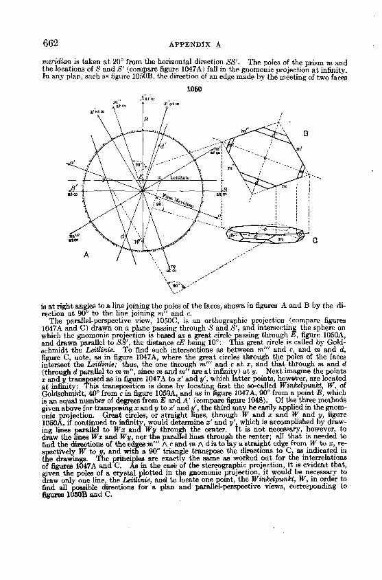
662 APPENDIX A
merididn is taken a t 20" from the horizontal direction SS'. The poles of the prism m and the locations of S and S' (compare figure 1047A) fall in the gnomonic projection a t infinity. In any plan, such as figure 1050B, the direction of an edge made by the meeting of two faces
1060
I' ',.---.. ,' '.,W ,+-' L'