appendix a – technical specifications
TRANSCRIPT

APPENDIX A – TECHNICAL SPECIFICATIONS
HERSCHEL STREET PUMP STATION FORCE MAIN REPLACEMENT
901 SCOPE OF WORK The scope of work specified herein includes the installation of approximately 3,115 LF of 16-inch PVC wastewater force main, 5 LF of 18-inch PVC wastewater force main, and 415 LF of 18-inch HDPE wastewater force main (via horizontal directional drill) along with associated fittings and appurtenances, along Herschel Street, Van Wert Avenue, and Oak Street, to replace the aging existing force main.
All Work shall be done in accordance with the January 2017 Edition of JEA Water and Wastewater Standards Manual. The following is a link to the JEA Water and Wastewater Standards Manual: https://www.jea.com/Engineering_and_Construction/Water_and_Wastewater_Standards/
The following scope of work will be defined as the base bid for this contract and shall include, but is not limited to, the following:
• Installation of approximately 3,115 LF of 16-inch PVC force main (via open cut), 5 LF of 18-inch PVC force main (via open cut), 415 LF of 18-inch HDPE force main (via horizontal directional drill), within City of Jacksonville (COJ) Right-of-Way (ROW) and JEA property
• Mobilization/demobilization, general requirements, and insurance
• Installation of Maintenance of Traffic (MOT) plans, devices, and measures to construct the project
• Installation/maintenance of erosion & sediment control devices/measures (E&SC) & other aspects of the stormwater pollution prevention plan (SWPPP)
• Site work
• Clearing, grading, seeding, and sodding
• Restoration of COJ Right-of-Way
• Installation of isolation valves and air/vacuum valves, and appurtenances as per the construction drawings
• Installation of connections to existing force mains
• Performance of all testing and swabbing required during construction
• Performance of all permits necessary to complete the work
• Performance of all site restoration to preconstruction (or better) condition
902 GENERAL CONDITIONS The General Conditions Lump Sum price shown on the Bid Form shall be compensation to complete the Work as required in this contract (except for items listed separately on the bid
JEA Herschel Street Pump Station EEXI9501 / Appendix A 1/5/2018 Force Main Replacement

APPENDIX A – pg 2 form), including but not limited to, Payment Bond, Performance Bond, Safety, Quality Control, Preparation of Daily Reports, Maintenance of Traffic, Attendance at Meetings, Scheduling, Testing (if not included elsewhere). Payment of the General Conditions Lump Sum Price shall be based upon the percentage of Work completed: however, if the Company executed bond(s) accompany the first pay request then the amount paid will be deducted from the associated subtotal. Also, the Company shall include the cost for performing survey of the existing roadway horizontal alignment (prior to initiating any construction or MOT) in their initial General Conditions payment. In the event that changes to the work are required that are covered under the Supplemental Work Authorization account, the General Conditions Lump Sum Price will not be increased unless the total value of the SWA exceeds the original SWA account provided in the original contract bid.
903 BID DRAWINGS Titled “Construction Drawings for Herschel Street Pump Station Force Main Replacement.” as prepared by Jacobs Engineering Group Inc. are attached.
904 GEOTECHNICAL REPORT Titled “Geotechnical Exploration and Evaluation Report; JEA Herschel Street Pump Station Force Main Replacement; Jacksonville, FL” prepared by CSI Geo, Inc., dated January 5th, 2018 is attached. The Company should review the geotechnical boring logs completed for this project.
905 RESPONSIBLE BIDDERS LIST (RBL) GC-11 LOCATE LINE VERIFICATION Upon request by JEA, Company shall identify which subcontractor on JEA’s RBL GC-11 Locate Line Services Verification listing will be utilized for the installation of locate wire on PVC piping. The Company may obtain a list of prequalified persons and/or companies by contacting the JEA Procurement Bid Section, 21 W. Church Street, Customer Center 1st Floor – Room 002, Jacksonville, FL 32202, (904) 665-6740, or by fax (904) 665-7294, or online at JEA.com.
906 PIPE UNIT COST Unit costs for pipes shall include all temporary pavements as necessary to restore the roadway after each working day, until final pavement repair is made.
907 NOISE The Company shall comply with the City of Jacksonville (COJ) noise ordinance. The Company is responsible for any deviations from the noise ordinance that will require a noise variance. The Company is responsible for obtaining the noise variance and all applicable fees in the event that one is required.
908 TIE-IN CONNECTIONS SEQUENCING CONSTRAINTS The following tie-in connections sequencing constraints are to emphasize critical tasks related to connections to existing systems for the work in this Contract. It is not a complete list of all work to be completed.
• Indicate required interruptions of existing operations on Progress schedule. Interruptions will be permitted to the extent that existing operation of the pump station will not be jeopardized and identified constraints are satisfied.
1/5/2018 EEXI9501 / Appendix A JEA Herschel Street Pump Station Force Main Replacement

APPENDIX A – pg 3
• Prior to commencing Work that requires existing operating facilities to be taken out of service, Company shall submit to JEA for review and approval, plans showing how the Work will be coordinated with JEA’s operations and maintenance.
• At least 14 days in advance, Company shall submit a detailed sequence of events, indicating the date and time for flow interruptions and/or diversions, and the duration of Work for the various events. Company's detailed written plan shall include operational considerations related to the Work, including method of flushing.
• All connections and ties to the existing system and transfer of services shall be performed by the Company under JEA’s direction. The Company shall not operate any valves in the existing system.
• Connection to the existing system may depend on the closure of certain valves. The existing valves may not be operable or may not seal properly. The Company shall coordinate with JEA in advance of the connections to determine the condition of existing valves.
• JEA reserves the right to postpone connections to existing utilities due to operational and/or weather related concerns.
• Work shall proceed continuously to complete connections in the minimum time. Minimize shutdown times by thorough advanced planning. Have required equipment, materials, and labor on hand at time of shutdown.
• Interruption of service is not allowed during peak flow periods or holidays. • Company shall anticipate performing the Work during daylight hours starting after 7:00
am and within an 8-hour maximum shutdown time. • Vactor Truck Allowance: JEA planning has included an allowance for five (5) 4,000
gallon trucks to be stationed at the Herschel Street Pump Station tie-in; and one (1) vactor truck and two (2) 4,000 gallon trucks to be stationed at the Oak Street/Riverside Avenue tie-in location. JEA will designate the pump stations that will require vactor trucks during the shutdown. The collected sewage shall be hauled to JEA’s pump station at 4140 Kingsbury Street or other pre-approved disposal location in a manner approved by JEA.
909 COMPANY’S USE OF PREMISES Company shall have complete use of the premises for the performance of the Work. Prior to mobilization, the Company’s Work Plan shall address its staging, storage, pipe stringing, pipe installation, and limits of disturbance areas within JEA’s Property and COJ ROW. Also, the Company shall coordinate activities with any other Company who will be performing work in the same general area.
All work shall take place within the JEA Property and the COJ ROW.
The Company is responsible for securing and obtaining any additional off site storage areas necessary.
Coordinate uses of premises with JEA, COJ, and any other contractors.
Company shall assume full responsibility for security of all its and its subcontractors’ materials and equipment stored on the site.
JEA Herschel Street Pump Station EEXI9501 / Appendix A 1/5/2018 Force Main Replacement

APPENDIX A – pg 4 If directed by the JEA or ENGINEER, move any stored items which interfere with operations of JEA or other contractors.
Company is responsible for obtaining and paying for the use of additional storage or work areas if needed to perform the work.
910 COMPANY’S STAGING, STORAGE AND STOCKPILE AREA No additional staging, storage, and stockpile will be made available by the JEA along the project site. The Company is not allowed to store any equipment or materials outside the right-of-way and JEA’s Property limits. The location will be agreed to upon and discussed at the pre-construction meeting.
911 PHASING Any COJ standard pavement repair shall be completed within 10 calendar days or when 500 LF of roadway is disturbed after completion of the utility installation. All mobilization/demobilization required for rework/regrading of lime rock base, dust control, including asphalt paving shall not be paid for separately but shall be included in the cost of the associated items in the Bid Form.
912 REMOVAL/ABANDONMENT OF UTILITIES UNDER ROADWAYS Water and sewer utilities to be abandoned under roadways shall be capped and grout filled for the length of the pipe under pavement.
913 REMOVAL/ABANDONMENT OF FORCE MAINS Company shall refer to the JEA General Conditions for the removal and abandonment of all force mains. Company shall take every precaution to avoid contamination of all water sources adjacent to the scope of this project. The Company shall exercise care to prevent spills onto the ground surface and shall immediately contain and clean up any spills at no extra cost to the Owner. The Company shall properly dispose of all waste and wastewater arising from grouting operations. Under no circumstance is grout to be discharged into water bodies.
914 EXISTING VALVES TO BE PLACE OUT OF SERVICE The measurement and payment for this item shall be in accordance with JEA’s Water and Sewer Standard as specified in Section 801.III.2. In addition to these requirements, the existing valve shall be closed, an MJ plug installed and the box and cover removed.
915 PERMITS AND PLANS APPROVALS JEA has applied for the following permits for the project:
• COJ Plan Approval – CDN 4161.245 • FDEP Permit to Construct a Domestic Wastewater Collection/Transmission System • FDEP Environmental Resource General Permit
Prior to commencing Work the Company is responsible for obtaining the following permits, including but not limited to:
• City of Jacksonville (COJ) Right-of-Way Permit • COJ Site Clearing Permit
1/5/2018 EEXI9501 / Appendix A JEA Herschel Street Pump Station Force Main Replacement

APPENDIX A – pg 5
• FDEP Generic Permit for Stormwater Discharge from Large and Small Construction Activities (CGP), DEP Form 62-621.300(4)(b)
o It is recommended that the Company acquire the FDEP dewatering permit as part of the Construction General Permit.
• FDOT General Use Permit (for MOT signage and detours utilizing FDOT right-of-way) • SJRWMD Notice to District of Dewatering Activity – Form 40C-2-900-12 • SJRWMD Individual Consumptive Use Permit if unable to qualify for general permit
under Rule 40C-2.042(9)
All costs associated with obtaining such permits shall not be paid for separately but shall be included in the cost of the associated item of work. The Company shall comply with all conditions of permits issued for the Work, either directly or indirectly, issued by federal, state, or local governmental agencies, which are hereby incorporated as part of these Contract Documents.
916 DEWATERING If the Company encounters groundwater, the Company shall be responsible for utilizing a dewatering system(s) to remove water from the excavations. Prior to beginning any dewatering activities, the Company shall comply with all requirements listed in Florida Department of Environmental Protection (FDEP) Dewatering Regulations.
Additionally, prior to any dewatering, the Company shall apply for a St. Johns River Water Management District (SJRWMD) Generic Permit for Short Term Dewatering, and comply with all SJRWMD requirements.
If the above requirements are not followed, the Company shall be held liable for any fines and/or violations incurred by JEA.
917 PERMIT COORDINATION MEETINGS Company shall be responsible for being thoroughly familiar with all permit requirements prior to mobilizing and starting work associated with a particular permit. If a permit requires a notification or meeting with the issuing agency prior to starting work, Company shall be responsible for arranging said meeting and informing the JEA Representative. The following shall attend, but not limited to, the Company's Project Manager, Company's Site Superintendent, Permitting Agency Representative, JEA Project Manager and JEA Inspector.
918 CONNECTIONS TO EXISTING WATER AND SEWER UTILITIES Company shall verify size and type of existing pipe at each connection prior to ordering materials for connections. All costs associated with connections to existing water and sewer utilities shall not be paid for separately but shall be included in the cost of the associated restraints/sleeves as shown in the plans or as approved by JEA.
919 TREE PROTECTION JEA performed a tree assessment along the force main route in August 2017 and provided the following guidelines for open-cut installation. The Company shall follow these guidelines unless otherwise directed by JEA.
JEA Herschel Street Pump Station EEXI9501 / Appendix A 1/5/2018 Force Main Replacement
APPENDIX A – pg 6
• Within the critical root zone (minimum approach distance), no storage of equipment, materials, or chemical based solutions.
• Within the critical root zone (minimum approach distance), create no change to the current drainage or water infiltration patterns.
• Within the critical root zone, (minimum approach distance), avoid cutting roots over 2 inches (50 mm) in diameter.
• Within the critical root zone (minimum approach distance) severed roots should be completed with a clean cut. A clean cut will encourage the growth of new roots more effectively than torn or crushed roots.
• Within the critical root zone (minimum approach distance), store/pile trenching soil on the opposite of the trench from the tree.
• Avoid physical injuries to tree trunks and crowns.
In general, trees up to 6 inches in diameter at breast height (DBH), trenching is not recommended closer to the tree than the existing drip line. For trees greater than 6 inches in diameter, a critical root zone is identified as a minimal approach distance for trenching. Minimal approach distance is calculated at 3 x DBH. A precautionary root zone is identified as the precautionary approach distance for trenching. Precautionary approach distance is calculated at 1 foot for every inch of tree DBH.
The Company shall coordinate with JEA’s Arborist to perform a pre-construction tree assessment. During construction the Company shall allow for periodic inspections by either JEA’s or COJ’s Arborist.
920 GRASSING/SODDING The Company shall replace all sod in-kind. St. Augustine type grass/sod will not be allowed in City of Jacksonville Right-of-Ways. All disturbed areas shall be restored by resodding (if grass was established pre-construction) or seeding and mulching in accordance with Section 441 of the JEA Water and Wastewater Standards Manual, titled, Grassing.
921 CLEARING AND GRUBBING Payment for clearing and grubbing shall not be paid for separately, but shall be included in the cost of the associated item of work. Payment will be compensation in full for all clearing and grubbing required for the roadway right-of-way and for any other clearing and grubbing indicated or required for the construction of the entire project area including area of excavated trenches and where trenchless operations are required, including all necessary hauling, furnishing equipment, equipment operation, furnishing any areas required for disposal of debris, leveling of terrain and the landscaping work of trimming, etc. as required.
922 LANDSCAPING The Company shall be responsible for protection and preservation of all trees, palms, shrubs, irrigation systems, landscaping, signs, and etc. along the route of the proposed work including hand digging, removal and storage of such and subsequent replacement to the fullest extent possible of the pre-existing condition. No trees shall be removed in the COJ Right-of-Way unless designated for relocation on the construction drawings. All costs associated with such
1/5/2018 EEXI9501 / Appendix A JEA Herschel Street Pump Station Force Main Replacement

APPENDIX A – pg 7 shall not be paid for separately but shall be included in the cost of the associated item of work shown on the Bid Form.
923 SWALE AND DITCH CONSTRUCTION / REGRADING The Company shall re-grade all existing swales and ditches as necessary to restore the swales and ditches to their original (or better) condition. No separate payment shall be made for re-grading or construction of new drainage ditches as required for restoration, but shall be included in the cost of the associated item of work shown on the Bid Form.
924 DUST CONTROL The Company shall utilize a water spray truck to mitigate dusty conditions when roadways are unpaved and construction areas have a lack of vegetative cover.
925 EARTHWORK It shall be the sole responsibility of the Company to evaluate the geotechnical findings and recommendations along with the construction drawings to determine the quantity of soil to be managed or removed/disposed and replaced in order to meet the requirements of the Contract Documents. No separate payment shall be made for stockpiling, managing, mixing, and/or removal, disposal, importation and placement of A-3 sand required for backfill and/or over-excavation (bedding) material for the pipeline(s) and structures, but all costs shall be merged with the associated item of work shown in the Bid Form. Excess and/or unsuitable material shall become the property of the Company and shall be disposed of outside of the right-of-way.
926 UPDATED SURVEYING In addition to the Surveying requirements set forth elsewhere in this solicitation, the Company shall be responsible for staking the project stationing, JEA Property and easements, and/or right-of-way boundaries. The survey datum used for this project is NAVD 1988. Staking shall be maintained throughout construction, including resurveying and restaking if the stakes are damaged or removed. All surveying shall be performed by a Professional Surveyor and Mapper (PSM) licensed in the State of Florida.
927 FORCE MAIN PROFILE ELEVATIONS The force main profile shown on the contract drawings indicate the station and elevation for the air/vacuum valves (ARV). The ARV must be located at a high point. To ensure this requirement is met, the Company shall take station and elevation readings of top of force main pipe at 100 foot intervals, and shall include additional elevation readings as necessary to capture all high points should any occur between the stated interval. The data collected shall be taken during the progression of the pipeline installation. Once the stations and elevations are collected, submit to the JEA Representative prior to installing the ARV. The JEA Engineer will review the elevations to determine if the station (location) for the ARV needs to be adjusted from that shown on the force main (FM) profile. If the Company installs the pipeline such that additional high points are created on the pipeline profile beyond that shown on the contract drawings, the company shall be solely responsible for furnishing and installing additional ARV/manholes at each of these high points. Elevations should be referenced to the survey benchmark.
JEA Herschel Street Pump Station EEXI9501 / Appendix A 1/5/2018 Force Main Replacement

APPENDIX A – pg 8 928 EXISTING UTILITIES Known surface and subsurface utilities are shown or noted on the drawings as accurately available information will permit. The JEA does not guarantee the information shown or noted or that utilities other than those indicated (on the Drawings) do not exist. It is the responsibility of the Company to notify each of the utilities at least (15) fifteen working days prior to construction and request that the location of their respective utility or material be located and staked in the field. Should the company encounter unidentified utility, work in the immediate area shall promptly cease and the JEA representative shall be advised. The JEA shall investigate the condition and propose remedial action. The Company is reminded of the laws of Florida requiring notification of Gas Company, at least four (4) working days in advanced of any digging operation. The Company shall call the Sunshine State One Call of Florida (811) to request location of all facilities owned by utilities that participate in the locate program. Failure by the company to contact Sunshine One Call of Florida prior to digging shall obligate the company for damages to participating utility company and associated repair cost.
In order to reduce the disruption and cost of utility damages occurring in the COJ ROW, JEA Property, and easements, the Company shall prevent damages to existing utilities caused by its work through field verification of the location of existing utilities. In the case of open excavation, verification may be performed during the Company’s work.
Company shall verify the location of existing utilities as needed to avoid contact. Existing utilities shall be exposed using detection equipment or other acceptable means. Such methods may include but shall not be limited to “soft dig” equipment and ground penetrating radar (GPR). The excavator shall be held liable for damages caused to the city’s infrastructure and the existing facilities of other utility companies.
929 COORDINATION OF CONSTRUCTION WITH EXISTING UTILITIES Company shall verify size and type of existing pipe at each connection prior to ordering materials for connections. All costs associated with connections to existing water and sewer utilities shall not be paid for separately, but shall be included in the cost of the associated line items shown on the Bid Form.
The Company shall establish liaison with and coordinate work with (including; but, not limited to) JEA, AT&T, TECO/Peoples Gas, and Comcast to prevent interference with overhead and buried electrical, telephone, and television cables. AT&T, TECO/Peoples Gas, Comcast and others will need time to relocate their facilities.
The Company shall at all times conduct his operation so as to interfere as little as possible with the existing utilities. The Company shall develop a program in cooperation with JEA and interested representatives of Utilities and City agencies, which shall provide for the construction of, and putting into service, the new work in the most orderly manner possible. This program shall be adhered to, except as deviations there from are expressly permitted. All work of connecting with, cutting into, and reconstructing existing pipes and structures shall be planned so as not to interfere with the operation of the existing utility.
1/5/2018 EEXI9501 / Appendix A JEA Herschel Street Pump Station Force Main Replacement
APPENDIX A – pg 9 930 UTILITY POLE HOLDING / SUSPENDING Holding or suspending of utility poles including power poles and telephone poles shall be performed as needed, and when trenching or excavating is within a horizontal distance from the pole that is less than the depth of the trenching or excavation. Work shall include, but not limited to, furnishing of all material, labor, supervision, tools, and equipment as required to hold/suspend utility poles. Company shall review the project and notify the JEA Project Manager of all anticipated holds/suspends within ten (10) days following the notice to proceed. JEA will be responsible for the coordination and provision of utility pole holds/suspends. Notice, giving the exact date and time, for each hold/suspend, shall be provided by the Company in writing to the JEA Project Manager at least two weeks in advance of each hold/suspend. No separate pay item will be made to the Company separately, but shall be included in the cost of the associated items in the Bid.
931 HORIZONTAL DIRECTION DRILLING SUPLLEMENT FOR JEA SECTION 755 OF THE JEA WATER AND WASTEWATER STANDARDS MANUAL, TITLED, HORIZONTAL DIRECTIONAL DRILLING (LARGE DIAMETER PIPE GREATER THAN 12 INCHES) AND SECTION 429 OF THE JEA WATER AND WASTEWATER STANDARDS MANUAL, TITLED, WASTEWATER FORCE MAINS
All pipe greater than 12-inch diameter installed by the Horizontal Directional Drilling method shall be in conformance to JEA Technical Specification Section 755 – Horizontal Directional Drilling and supplemental requirements below. In case of contradictory information, the supplemental requirements take precedence over Section 755 and Section 429. The Measurement and Payment for this item shall be in accordance with JEA’s Water and Sewer Standard as specified in Section 801.XXIV.
• Materials: High Density Polyethylene (HDPE) pipe shall meet the requirements of Section 755 with the additional requirement that the material used to manufacture the pipe shall be PE4710 high density polyethylene meeting cell classification 345464C per ASTM D3350, and the HDPE pipe shall conform to AWWA C906, DR-11, Ductile Iron Pipe (DIP) size and NSF 61 Standard.
• Equipment: Pipe rollers are required for HDPE pipe support. Pipe shall not be dragged on the ground.
• Pilot Hole Elevation: The pilot hole tolerance is +/- 5 feet of the path shown on the Drawings.
• Pullback: Buoyancy control measures are required for pullback. HDPE pipe shall be welded/fused together in one length and pulled back without stopping work.
• HDPE Pipe Testing: Prior to pullback, the HDPE pipe shall be pressure tested in accordance with JEA Section 755. After pullback, the HDPE pipe shall be again pressure tested in accordance with JEA Section 755.
• HDD operations shall comply with the COJ Noise Ordinance.
JEA Herschel Street Pump Station EEXI9501 / Appendix A 1/5/2018 Force Main Replacement

APPENDIX A – pg 10 932 VALVE AND LOCATE WIRE BOX IDENTIFICATION MARKERS The Company shall furnish and install fiberglass identification markers at all gate valve and locate wire box locations as directed by the JEA Representative. All costs associated with this work shall be included in the associated line item in the Bid Document.
933 COJ PAVEMENT MARKING REQUIREMENTS • Pavement markings should be placed as shown on the plans and detail sheets. If no
specific striping comments are noted on the drawings, the Company shall replace damaged/removed striping due to construction activities with like striping and/or reflectors.
• Any required temporary markings must be in place before opening lanes of traffic. Pay items for temporary pavement markings are to be included in the tabulation of quantities.
• The removal of existing pavement markings will be considered an incidental item with no additional compensation provided.
• All permanent pavement markings shall be extruded thermoplastic and meet current City of Jacksonville specifications and FDOT standard specifications, latest edition.
• Thermoplastic pavement markings are to be placed no sooner than 30 calendar days after the completion of the final pavement layer.
• A bituminous reflective pavement marker (RPM) adhesive meeting current City of Jacksonville and/or FDOT specifications shall be used on asphalt roadways.
• The Company shall use 4”x4” CLASS –B reflective pavement markers (RPMs) installed to meet current City of Jacksonville specifications and/or FDOT standard specifications. Acceptable examples are: Ennis Paint Co., Model 911; Ray-O-Lite, Model AA-ARCII-FH; Apex, 921AR.
• Reflective pavement markers that do not conflict with permanent (thermoplastic) markings shall be placed on all final asphaltic concrete surfaces immediately after the temporary permanent striping is in place.
The Company SHALL contact the Pavement Marking Inspector (Danny Howard - 904-255-7550) 48 hours PRIOR to installing any pavement markings of any City of Jacksonville roadway or streets.
934 ROADWAY RESTORATION Company shall perform survey of existing roadway horizontal alignment and vertical grade and of the existing structures and appurtenances for the Work area prior to initiating any construction. No separate payment shall be made, but all costs shall be included in the lump sum cost of the General Conditions line items. Intent is to restore existing roadway, structures and appurtenances to existing alignment, width, and grade to match existing elevations after construction is performed.
Damage to existing features, including but not limited to asphalt, sidewalks, curb and gutter, drives, fencing, signs, and lights, will be replaced at the Company’s expense unless otherwise authorized by JEA.
Damage to existing granite curb will be replaced with the same type and material at the Company’s expense.
1/5/2018 EEXI9501 / Appendix A JEA Herschel Street Pump Station Force Main Replacement

APPENDIX A – pg 11 935 TRAFFIC SIGNAGE Costs incurred by the Company to provide new signage and pavement markers, or remove and replace existing signage as necessary to accomplish the work shall not be paid for separately but shall be merged with the cost of the associated item of work. Damaged signage shall be replaced with new signage. All signage and pavement markers shall be in accordance with the drawings and COJ and FDOT requirements.
936 UPDATED AS BUILTS Upon submission of each payment application, Company shall furnish to the JEA Engineer a photocopy “redline” set of drawings identifying those field changes made to the Work to date, along with a photocopy set of the associated field notes. Revisions and recording of information on the photocopy set of drawings shall be done in scale in red ink clearly and accurately identifying those changes in the Work by a competent drafter. All “As-Built” information shall be recorded and kept current during the progress of the Work. The JEA Engineer may review and comment on the drawings which shall be incorporated into the next month’s as-built submittal. Failure to incorporate changes the following month may result in denial of pay application request. These requirements only supplement the requirements of the General Conditions.
When the payment of application submitted includes associated items of final restoration for a project, or a portion of the project thereof, then the associated final as-builts shall be submitted as a “redline” marked photocopy set of drawings for that pay period. The JEA Engineer may review and comment on the drawings with the view toward final as-built submittal. The subsequent month submittal made with the payment application shall incorporate a photocopy set of CADD drawing final as-builts. The JEA Engineer shall review and comment on the photocopy set of CADD drawings which shall be incorporated into the final as-built submittal. These requirements only supplement the requirements of the General Conditions.
937 QUALITY CONTROL AND QUALITY ASSURANCE The Company shall provide Quality Control to ensure the Work is performed in accordance with the Contract. Quality Control shall be appropriate for the nature of the Work, and shall be conducted in a manner consistent with sound quality management and industrial engineering principles. The Company shall have only personnel trained in Quality Control techniques and experienced with the nature of the Work perform the Quality Control function.
JEA may perform Quality Assurance activities. Such activities whether performed or not, do not in any way limit or reduce the Company's requirements. JEA may become aware of quality related problems during its performance of Quality Assurance, but has no obligation to notify the Company of its findings. The Company shall provide access to all areas of Work, including the Company's facilities, for JEA Quality Assurance personnel and JEA Representatives. JEA will conduct Quality Assurance activities so as not to excessively interfere with the Work, however, where JEA Quality Assurance personnel request specific actions of the Company, the Company shall comply with the request and agrees that such compliance is included as part of its Contract Price.
JEA Herschel Street Pump Station EEXI9501 / Appendix A 1/5/2018 Force Main Replacement

APPENDIX A – pg 12 938 REPORTING The Company shall provide daily reports and other reports as defined in the Contract Documents.
Where the reporting frequency is daily, reports shall be submitted by noon of the following workday. Where the reporting frequency is weekly, reports are due by Monday at noon, covering the prior workweek. Where Monday is a Holiday, the reports are due at noon on the next workday. Where reports are due monthly, reports are due by noon on the first business day of each month. Sample forms for reports may be included in the Contract Documents. Where they are included they are to be used. Where they are not included, the Company shall provide a sample of its proposed report format for each report to the Contract Administrator at least one-week prior to its initial due date. The JEA Engineer will review and either approve or reject use of the report. Where proposed report is rejected, Company shall resubmit revised report formats, until JEA Engineer approves format. Reporting cycle shall begin upon PO date, or, if used, date of Notice to Proceed.
939 JEA COMPANY / SUBCONTRACTOR SAFETY REQUIREMENTS Company and Subcontractors must be prequalified under JEA’s safety prequalification program. Bids from Companies not prequalified under the safety program will not be opened. Subcontractors do not need to be safety prequalified at time of bid opening, but must prequalified before they step on the jobsite. To inquire as to status of safety prequalification, contact Jerry Fulop, JEA, 21 W. Church Street, Jacksonville, FL 32202, (904) 665-5810, e-mail: [email protected]
Company agrees to abide by all JEA’s Safety Rules and Regulations in accordance with JEA Company Safety Requirement. In addition, ALL Company employees will be required to attend and successfully complete Company’s orientation and supervisor’s training at Company’s expense prior to the start of any work activities. This is a condition of employment for Company and Subcontractors who perform work for JEA. There will be at least four (4) categories of training mandated. 1) Orientation, 2) Supervisor, 3) Competent Person, and 4) Certified Flagger.
ORIENTATION - Required one day training class for ALL personnel working at JEA’s sites. Acceptable training will be EITHER attendance at an OSHA 10 hour class in the last two years (will require an OSHA issued card for proof) or attend the NCCER (National Center for Construction Education and Research) 8 hour Orientation. Company personnel utilizing the OSHA 10 Hour class must also attend the JEA 2-Hour Operation specific training. This training must be completed prior to starting work on a JEA job site.
SUPERVISOR - Orientation and the JEA Safety Leadership Development (SLD) Class. This requirement is for ALL employees paid as a foreman, general foreman, superintendent or any employee that will direct or may be expected to direct work.
CERTIFIED FLAGGER – All Company’s performing any construction to or on City of Jacksonville, or State of Florida streets and highways shall provide certified flaggers to direct traffic in accordance with the approved MOT of the project.
1/5/2018 EEXI9501 / Appendix A JEA Herschel Street Pump Station Force Main Replacement

APPENDIX A – pg 13 NOTE: OSHA ten (10) hour classes are available from the following: Trained and Certified OSHA Instructors, Consultants, Safety Councils, etc. Other training mandated by JEA has been developed and approved by the NCCER. This training will be available from Certified Master Instructors, JEA, Northeast Florida Safety Council or other approved sources and will be tracked in the form of an individual transcript for each employee by NCCER.
Company may request exemption for specialty work based on task to be performed, hazard involved, and duration of work.
JEA Herschel Street Pump Station EEXI9501 / Appendix A 1/5/2018 Force Main Replacement

APPENDIX A – pg 14
THIS PAGE INTENTIONALLY LEFT BLANK
1/5/2018 EEXI9501 / Appendix A JEA Herschel Street Pump Station Force Main Replacement

APPENDIX B BID FORM FOR SOLICITATION # 057-18
Construction Services for Herschel St PS FM Replacement from Herschel St to Challen Ave
Submit an original, two (2) copies and one (1) CD along with other required forms in a sealed envelope to: JEA Procurement Dept., 21 W. Church St., Bid Office, Customer Center, 1st Floor, Room 002, Jacksonville, FL 32202-3139. Company Name: Company’s Address License Number Phone Number: FAX No: Email Address: BID SECURITY REQUIREMENTS TERM OF CONTRACT
None required One Time Purchase Certified Check or Bond Five Percent (5%) Annual Requirements
Other, Specify- Project Completion SAMPLE REQUIREMENTS SECTION 255.05, FLORIDA STATUTES CONTRACT BOND
None required None required Samples required prior to Bid Opening Bond required 100% of Bid Award Samples may be required subsequent to
Bid Opening QUANTITIES INSURANCE REQUIREMENTS
Quantities indicated are exacting Quantities indicated reflect the approximate quantities to be purchased Insurance required
Throughout the Contract period and are subject to fluctuation in accordance with actual requirements. PAYMENT DISCOUNTS
1% 20, net 30 2% 10, net 30 Other None Offered
Item No.
ENTER YOUR BID FOR THE FOLLOWING DESCRIBED ARTICLES OR SERVICES: Construction Services for Herschel St PS FM Replacement
from Herschel St to Challen Ave TOTAL BID PRICE
1 Enter TOTAL BID PRICE from Appendix B- Bid Workbook $________________________
I have read and understood the Sunshine Law/Public Records clauses contained within this solicitation. I understand that in the absence of a redacted copy my proposal will be disclosed to the public “as-is”.
BIDDER'S CERTIFICATION By submitting this Bid, the Bidder certifies that it has read and reviewed all of the documents pertaining to this Solicitation, that the person signing below is an authorized representative of the Bidder’s Company, that the Company is legally authorized to do business in the State of Florida, and that the Company maintains in active status an appropriate contractor’s license for the work (if applicable). The Bidder also certifies that it complies with all sections (including but not limited to Conflict Of Interest and Ethics) of this Solicitation, and that the Bidder is an authorized distributor or manufacturer of the equipment that meets the Technical Specifications stated herein.
We have received addenda _____________
Handwritten Signature of Authorized Officer of Company or Agent Date
_______ through _______
Printed Name and Title

APPENDIX B - LIST OF SUBCONTRACTORS FORM 057-18 Construction Services for Herschel St PS FM Replacement from Herschel St to Challen Ave
JEA Solicitation Number 022-18 requires certain major Subcontractors be listed on this form, unless the work will be self-performed by the Company.
The undersigned understands that failure to submit the required Subcontractor information on this form will result in bid rejection, and the Company agrees to employ the Subcontractors specified below: (Use additional sheets as necessary)
Note: This list of Subcontractors shall not be modified subsequent to bid opening, without a showing of good cause and the written consent of JEA.
Type of Work Corporate Name of Subcontractor, If
Self Performing the work enter “Self-
Perform”
Subcontractor Primary Contact
Person & Telephone Number
Subcontractor’s License Number (if
applicable)
Percentage of Work or Dollar Amount
Horizontal Directional Drilling (HDD)
Signed:
Company:
Address:
Date:

Appendix B - Minimum Qualification Form #057-18 Construction Services for Herschel St PS FM Replacement from Herschel St to Challen Ave
GENERAL
THE MINIMUM QUALIFICATIONS SHALL BE SUBMITTED ON THIS FORM. IN ORDER TO BE CONSIDERED A QUALIFIED BIDDER BY JEA YOU MUST MEET THE MINIMUM QUALIFICATIONS LISTED BELOW, AND BE ABLE TO PROVIDE ALL THE SERVICES LISTED IN THIS SOLICITATION/TECHNICAL SPECIFICATION. THE BIDDER MUST COMPLETE THE BIDDER INFORMATION SECTION BELOW AND PROVIDE ANY OTHER INFORMATION OR REFERENCE REQUESTED. THE BIDDER MUST ALSO PROVIDE ANY ATTACHMENTS REQUESTED WITH THIS MINIMUM QUALIFICATIONS FORM. PLEASE SUBMIT THE ORIGINAL AND TWO (2) COPIES AND ONE (1) CD OF THIS FORM AND ANY REQUESTED ADDITIONAL DOCUMENTATION WITH THE BID SUBMISSION. BIDDER INFORMATION COMPANY NAME: BUSINESS ADDRESS: CITY, STATE, ZIP CODE: TELEPHONE: FAX: E-MAIL: PRINT NAME OF AUTHORIZED REPRESENTATIVE: SIGNATURE OF AUTHORIZED REPRESENTATIVE: NAME AND TITLE OF AUTHORIZED REPRESENTATIVE: MINIMUM QUALIFICATIONS: Bidder shall have the following Minimum Qualifications to be considered eligible to submit a Bid in response to this Solicitation.
Bidder must have a State of Florida Underground Utility and Excavation Contractor License. Bidder shall provide the license number where indicated on Appendix B - Bid Form
At the Bid Due Date and Time, the Bidder must be on the Responsible Bidder List (RBL) for category:
RBL – WM2 – Water, Sewer Reclaim Pressure Pipe Construction Underground Trench <24” Diameter
For any questions regarding RBL qualification and current status, contact Lynn Rix at: 904-665-6740 or at [email protected].
The required Horizontal Drilling (HDD) for this project may be self-performed or sub-contracted. Whether self-performed or sub-contracted, the (HDD) Contractor shall also meet the following minimum requirements to be included in a Bid to IFB 057-18. The following documentation shall be provided in the submittal:
The HDD Contractor must have successfully completed the installation of one (1) HDD project within the last ten (10) years of the Bid Due Date, with the project containing a minimum pipe diameter of at least sixteen inches (16”) and an overall single pull/drill length of at least 500 LF.

Appendix B - Minimum Qualification Form #057-18 Construction Services for Herschel St PS FM Replacement from Herschel St to Challen Ave
Bidder shall provide information where indicated below.
HORIZONTAL DIRECTIONAL DRILL (HDD) REQUIREMENTS HDD PROJECT (1) Company Name Company Contact Name Company Contact Phone Number
Company Contact E-Mail Address Project Completion Date Pipe Diameter (“) Overall Single Pull Length (Linear Feet) Description of Project

Geotechnical Exploration and Evaluation Report
JEA Herschel Street Pump Station Force Main Replacement
Jacksonville, Florida
CSI Geo Project No.: 71-16-166-07
Jacobs Subcontract No.: EEXI9500-I17-0002
Jacobs Project No.: EEXI9502
JEA Project No.: 153004 (PO 166955)
Prepared by
CSI Geo, Inc.
2394 St. Johns Bluff Road S., Suite 200
Jacksonville, FL 32246
Tel: (904) 641-1993
Fax: (904) 641-0057
Prepared for
Jacobs Engineering Group Inc.
January 5, 2018


TABLE OF CONTENTS SECTION PAGE NUMBER 1.0 Project Information .............................................................................. 1
1.1 General Project Information 1.2 Existing Conditions and Project Description
2.0 Geotechnical Exploration ..................................................................... 2
2.1 Field Exploration 2.2 Laboratory Testing 2.3 Existing Pavement System Thickness
3.0 General Subsurface Conditions ........................................................... 3 3.1 General
3.2 Soil Conditions 3.3 Groundwater Conditions
4.0 Design Recommendations .................................................................... 5 4.1 General 4.2 Open-Cut Excavations 4.3 Horizontal Directional Drilling (HDD)
4.3.1 Drilling Difficulties 4.3.2 Recommended Design Soil Parameters
5.0 Site Preparation & Earthwork Recommendations ............................ 7
5.1 Existing Utilities 5.2 Temporary Groundwater Control 5.3 Excavation Protection 5.4 Pipe Backfill and Compaction of Pipe Backfill
6.0 Report Limitations ................................................................................ 9 APPENDIX Site Location Map Field Exploration Plan Report of Core Borings Summary of Laboratory Test Results Existing Pavement System Thickness Recommended Design Soil Parameters for Horizontal Directional Drilling Key to Soil Classification Field and Laboratory Test Procedures

JEA Herschel Street Pump Station Force Main – Jacksonville, Florida Page 1 of 9
1.0 PROJECT INFORMATION
1.1 General Project Information
The purpose of this geotechnical exploration program was to collect information concerning the
subsurface conditions in order to evaluate the site with respect to the proposed JEA Herschel
Street pump station force main replacement in Jacksonville, Florida. This report describes the
field and laboratory testing activities performed and presents the findings. The subsurface soil
and groundwater conditions are presented in this report along with general site preparation
recommendations and design soil parameters for the proposed construction.
Information regarding this project was provided to CSI Geo, Inc. (CSI Geo) by Ms. Christine
Ellenberger, P.E. of Jacobs Engineering Group Inc. (Jacobs). The following document was
provided to us in electronic format.
Herschel Street Pump Station Force Main Replacement Plan & Profile
Drawing No. C-1.01, Sheets 5 to 10
Dated: November 2017
1.2 Existing Conditions and Project Description
The project site corridor is located in the Avondale area in Jacksonville, Florida. A new 16-inch
force main is proposed to be installed along Herschel Street, Van Wert Avenue, and Oak Street
starting at the Herschel Street pump station to the south and ending at the intersection of Oak
Street and Riverside Avenue to the north. The general site location is shown on the site location
map included in the Appendix. In general, the overall topography of the site slopes gently from
southwest to the northeast. The proposed 16-inch force main will generally be installed using
open-cut pipe installation methods. In addition, it is our understanding the pipe will be installed
using Horizontal Directional Drilling (HDD) for the pipe section to be installed under the culvert
at Little Fishweir Creek along Herschel Street.

JEA Herschel Street Pump Station Force Main – Jacksonville, Florida Page 2 of 9
2.0 GEOTECHNICAL EXPLORATION
2.1 Field Exploration
The force main sections proposed to be installed by means of open cut method of installation
were explored by means of a total of 10 auger borings (A-1 through A-10), and drilled to a depth
of 10 feet below the existing ground surface. The area of pipe installation by means of HDD
method was explored by means of a total of two Standard Penetration Test (SPT) borings (B-1
and B-2), drilled to a depth of 40 feet below the existing ground surface.
The boring locations and depths were determined by Jacobs and located in the field by personnel
from CSI Geo. Soil samples collected were visually classified in the field and then transported
to our laboratory for re-classification and testing. The approximate locations of the soil borings
are shown on the Field Exploration Plan sheets included in the Appendix.
2.2 Laboratory Testing
Representative soil samples obtained during our field exploration program were visually
classified using the American Association of State Highway and Transportation Officials
(AASHTO) Soil Classification System and the Unified Soil Classification System (USCS).
Quantitative laboratory testing was performed on representative soil samples to better define
their composition. Laboratory tests performed were percent fines, natural moisture content,
Atterberg limits, and organic content. A Summary of Laboratory Test Results, and Field and
Laboratory Test Procedures are included in the Appendix.
2.3 Existing Pavement System Thickness
Nine (9) pavement cores were performed along the existing pavements at boring locations A-2
through A-10 to determine the pavement system thicknesses. The results of the pavement coring
indicate that the asphalt thickness ranged from 2 to 6 inches over 4-1/2 to 7-1/2 inches of
limerock. Detailed results of the existing pavement system thickness are included in the
Appendix. Limerock was not encountered at boring locations A-2, A-3, A-4 and A-6.

JEA Herschel Street Pump Station Force Main – Jacksonville, Florida Page 3 of 9
3.0 GENERAL SUBSURFACE CONDITIONS
3.1 General
An illustrated representation of the subsurface conditions encountered in the proposed
construction areas is shown on the Report of Core Borings sheets presented in the Appendix.
The Report of Core Borings and the soil conditions outlined below highlight the major
subsurface stratification. The Report of Core Borings should be consulted for a detailed
description of the subsurface conditions encountered at each boring location. When reviewing
the Report of Core Borings, it should be understood that soil conditions may vary outside of the
explored areas.
3.2 Soil Conditions
Open-cut Method of Pipe Installation
Review of auger borings A-1 through A-10 indicates that the force main alignment is generally
underlain by fine sands and slightly silty fine sands (A-3), silty fine sands (A-2-4), and clayey
fine sands (A-2-6) until the boring termination depth of 10 feet below the existing grades.
Horizontal Directional Drilling Areas
Review of test borings B-1 and B-2 indicates that the force main alignment across Little Fishweir
Creek is generally underlain by very loose to loose sands (SP) and slightly silty sands (SP-SM)
in the upper 9 to 11 feet of depth below the existing grades followed by unsuitable soils
consisting of very loose organic silty sands (PT) to a depth of 17 feet in boring B-1 and 12 feet in
boring B-2. Beneath these soils, very soft to firm clays (CH), medium dense clayey sands (SC),
hard clays (CH/Marl) and moderately weathered limestone were encountered until the borings
termination depth of 40 feet below the existing grades.
3.3 Groundwater Conditions
The groundwater level was measured and recorded as encountered at the time of drilling. The
depths of the groundwater level and estimated seasonal high water level at the test locations are
marked on the Report of Core Borings sheets presented in the Appendix. The depth of
groundwater level measured at the time of drilling ranged from 2.5 to 7 feet below the existing
grades. The estimated seasonal high groundwater table for the borings performed ranged from 2

JEA Herschel Street Pump Station Force Main – Jacksonville, Florida Page 4 of 9
to 6 feet below the existing grades. It should be anticipated that the groundwater level will
fluctuate due to seasonal climate variations, surface water runoff patterns, construction
operations, tidal effects, and other related factors.

JEA Herschel Street Pump Station Force Main – Jacksonville, Florida Page 5 of 9
4.0 DESIGN RECOMMENDATIONS
4.1 General
Our geotechnical evaluation of the site and the subsurface conditions is based on our
understanding of the proposed project, our observations, and results of field and laboratory
testing. The recommendations provided in this report present construction methods and
techniques that are appropriate for the proposed construction. If the project location is changed
or if field conditions encountered during construction are different from those presented in this
report, the information should be provided to CSI Geo for evaluation. We also recommend that
CSI Geo be given the opportunity to review the design plans and specifications to ensure that our
recommendations have been properly included and implemented.
4.2 Open-cut Excavations
In general, we consider the subsurface soil conditions at the site to be favorable for support of the
proposed pipe over a properly prepared and compacted subgrade, provided that the site
preparation and earthwork construction recommendations in this report are performed.
The A-3 type soils are considered select material. Silty fine sands (A-2-4) can be treated as
select material, however, they may contain excess moisture and may be difficult to dry and to
compact.
Clayey fine sands (A-2-6) and sandy clays (A-6/A-7), if encountered, should be considered
plastic materials. Therefore, they should be excavated to a minimum depth of one foot below the
design invert elevations and replaced with suitable A-3 fill material. Organic soils (A-8) should
be considered as muck and not suitable for use as backfill. If A-8 materials are encountered
beneath the force main or other proposed structures they should be removed in their entirety.
It is cautioned that portions of the pipe alignment are underlain by plastic clayey fine sands
(A-2-6). These soils should be replaced with select A-3 material prior to the installation of the
force main.

JEA Herschel Street Pump Station Force Main – Jacksonville, Florida Page 6 of 9
It is very likely that the excavated suitable soils will get mixed with plastic soils during
construction. Therefore, it is our opinion that some of the excavated material, if mixed with
plastic soils, should be regarded as unsuitable for backfill purposes. We recommend that
allowance be made for overruns in quantities of subsoil removal and replacement with select
backfill. It should be noted that plastic soils boundaries and limits are approximate and represent
soils encountered at each boring location. Subsurface variance between borings may occur and
should be anticipated.
We anticipate that the buried pipe lines will exert little downward pressure on the subgrade soils.
In areas where the surrounding groundwater level is above the pipe invert elevation, the line
should be designed to resist lateral earth pressures and hydrostatic uplift pressures appropriate to
its depth below the existing grade and the seasonal high water level.
4.3 Horizontal Directional Drilling (HDD)
We understand that Horizontal Directional Drilling method of installation will be used to install
the force main across Little Fishweir Creek. We recommend that soil parameters and
assumptions to be used for the project follow the latest JEA Water & Wastewater Standards
Manual as well as the recommendations provided below.
4.3.1 Drilling Difficulties
If the HDD alignment extends into the harder Marl and/or moderately weathered limestone
encountered below the depth of about 28 feet (approximate Elev. -20’), drilling is anticipated to
be considerably slower compared to upper soils.
4.3.2 Recommended Design Soil Parameters
We recommend that soil parameters and assumptions for the horizontal directional drilling
design follow the information provided in the Recommended Design Soil Parameters for
Horizontal Directional Drilling tables included in the Appendix.

JEA Herschel Street Pump Station Force Main – Jacksonville, Florida Page 7 of 9
5.0 SITE PREPARATION & EARTHWORK RECOMMENDATIONS
5.1 Existing Utilities
The locations of existing utilities should be established prior to construction. Provisions should
be made to relocate utilities interfering with the proposed alignments and construction, as
needed. Underground pipes that are not operational should be either removed or plugged
otherwise they may become conduits for subsurface erosion and cause settlements.
5.2 Temporary Groundwater Control
Groundwater level was encountered at the time of drilling at a depth ranging from 2.5 to 7 feet
below the existing grades. Therefore, groundwater control should be anticipated. The
groundwater level should be maintained at a minimum of two feet below the subgrade of the
proposed inverts. Dewatering may be achieved by conventional open pumping using ditches
graded to a sump or by using a well point system. Dewatering should continue until sufficient
weight is placed over the proposed pipes to resist uplift.
5.3 Excavation Protection
All excavations should meet OSHA Excavation Standard Subpart P regulations for Type C soils.
A trench box or braced sheet pile structures may be considered to support open excavations. The
soil support system should be designed according to OSHA by a Florida registered Professional
Engineer.
5.4 Pipe Backfill and Compaction of Pipe Backfill
The A-3 type soils are considered select material and suitable for use as backfill. Some of the
excavated soils during pipe installations are anticipated to consist of silty sands (A-2-4), plastic
clayey sands (A-2-6), sandy clays (A-6/A-7), and organic soils (A-8), which should be
considered unsuitable for backfilling and compaction purposes. As mentioned earlier, some of
the excavated suitable soils will likely get mixed with plastic soils during construction.
Therefore, some of the excavated material, if mixed with plastic soils, should be regarded as
unsuitable for backfill purposes. We recommend that allowance be made for overruns in
quantities of subsoil removal and replacement with select (A-3) backfill.

JEA Herschel Street Pump Station Force Main – Jacksonville, Florida Page 8 of 9
The backfill material within the excavation should be placed in thin loose lifts not exceeding 6
inches in thickness. The backfill material should be compacted by the use of hand-operated
equipment. The backfill material should be granular (A-3) fill with less than 10 percent material
passing the no. 200 mesh sieve and containing less than 3 percent organic matter. The backfill
material should be compacted to a minimum density of 98% or 95% of maximum dry density
obtained from the Modified Proctor compaction test (ASTM D1557), as required by JEA. The
moisture content during compaction should be maintained within + 3 percent of the optimum
moisture content as obtained from the Modified Proctor compaction test.
Hand held compaction equipment should be used for the backfill placed around the pipe and to a
height of 2 feet above the pipe. Heavier equipment may be used on the remaining backfill lifts
placed above 2 feet. However, care should be taken not to damage the pipe below. The pipe
should be designed to withstand the anticipated dead (overburden) and live loads.

JEA Herschel Street Pump Station Force Main – Jacksonville, Florida Page 9 of 9
6.0 REPORT LIMITATIONS
The subsurface exploration program including our evaluation and recommendations was
performed in general accordance of accepted geotechnical engineering principles and standard
practices. CSI Geo is not responsible for any independent conclusions, opinions, or
interpretations made by others based on the data presented in this report.
This report does not reflect any variations that may occur adjacent or between soil borings. The
discovery of any site or subsurface condition during construction that deviates from the findings
and data as presented in this report should be reported to CSI Geo for evaluation. If the location
of the proposed force main is changed, our office should be contacted so our recommendations
can be re-evaluated. We recommend that CSI Geo be given the opportunity to review the final
design drawings and specifications to ensure that our recommendations are properly included
and implemented.

APPENDIX
Site Location Map Field Exploration Plan Report of Core Borings Recommended Design Soil Parameters for Horizontal Directional Drilling (HDD) Summary of Laboratory Test Results Existing Pavement System Thickness Key to Soil Classification Field and Laboratory Test Procedures

Site Location Map


Field Exploration Plan


Report of Core Borings


Recommended Design Soil Parameters
for Horizontal Directional Drilling (HDD)
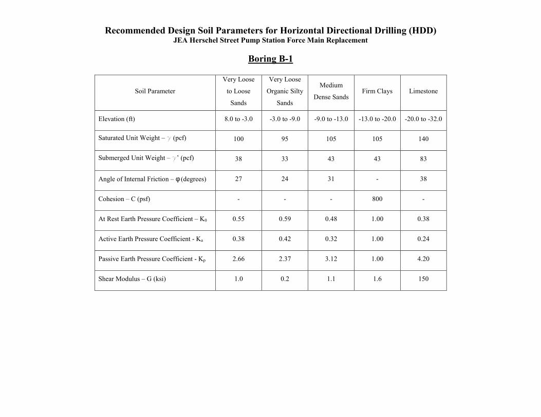
Recommended Design Soil Parameters for Horizontal Directional Drilling (HDD) JEA Herschel Street Pump Station Force Main Replacement
Boring B-1
Soil Parameter
Very Loose
to Loose
Sands
Very Loose
Organic Silty
Sands
Medium
Dense Sands Firm Clays Limestone
Elevation (ft) 8.0 to -3.0 -3.0 to -9.0 -9.0 to -13.0 -13.0 to -20.0 -20.0 to -32.0
Saturated Unit Weight – g (pcf) 100 95 105 105 140
Submerged Unit Weight – g’ (pcf) 38 33 43 43 83
Angle of Internal Friction – φ (degrees) 27 24 31 - 38
Cohesion – C (psf) - - - 800 -
At Rest Earth Pressure Coefficient – K0 0.55 0.59 0.48 1.00 0.38
Active Earth Pressure Coefficient - Ka 0.38 0.42 0.32 1.00 0.24
Passive Earth Pressure Coefficient - Kp 2.66 2.37 3.12 1.00 4.20
Shear Modulus – G (ksi) 1.0 0.2 1.1 1.6 150

Recommended Design Soil Parameters for Horizontal Directional Drilling (HDD) JEA Herschel Street Pump Station Force Main Replacement
Boring B-2
Soil Parameter
Very Loose
to Loose
Sands
Very Loose
Organic Silty
Sands
Very Soft
Sandy Clay
Loose Silty
Sands
Medium
Dense Clayey
Sands
Hard Clays Dense Sands
Elevation (ft) 9.0 to 0.0 0.0 to -3.0 -3.0 to -8.5 -8.5 to -11.5 -11.5 to -18.0 -18.0 to -27.0 -27.0 to -31.0
Saturated Unit Weight – g (pcf) 100 95 90 100 115 120 120
Submerged Unit Weight – g’ (pcf) 38 33 28 38 53 58 58
Angle of Internal Friction – φ (degrees) 27 24 - 26 31 - 34
Cohesion – C (psf) - - 200 - - 2,000 -
At Rest Earth Pressure Coefficient – K0 0.55 0.59 1.00 0.56 0.48 1.00 0.44
Active Earth Pressure Coefficient - Ka 0.38 0.42 1.00 0.39 0.32 1.00 0.28
Passive Earth Pressure Coefficient - Kp 2.66 2.37 1.00 2.56 3.12 1.00 3.54
Shear Modulus – G (ksi) 1.0 0.6 0.2 0.7 2.0 5.0 3.0
Summary of Laboratory Test Results

#4 #10 #40 #60 #100 #200 LL Pl
A-1 4 5.0 - 6.0 18 4 A-3
A-2 4 6.0 - 7.0 25 8 A-3
A-3 5 8.0 - 9.0 22 15 A-2-4
A-3 6 9.0 - 10.0 21 21 A-2-4
A-4 3 5.0 - 6.0 24 20 A-2-4
A-4 5 9.0 - 10.0 24 15 A-2-4
A-5 2 2.0 - 3.0 23 34 37 18 A-2-6
A-5 4 6.0 - 7.0 20 24 A-2-4
A-6 3 4.0 - 5.0 24 31 29 7 A-2-4
A-6 6 7.0 - 8.0 21 33 39 25 A-2-6
A-7 4 6.0 - 7.0 21 20 A-2-4
A-7 5 7.0 - 10.0 19 28 32 15 A-2-6
A-8 5 8.0 - 9.0 20 26 26 7 A-2-4
A-9 4 7.0 - 8.0 23 30 30 8 A-2-4
A-10 5 6.0 - 7.0 23 29 29 8 A-2-4
A-10 3 4.0 - 5.0 22 9 A-3
Percent Passing Sieve Size (%) Atterberg LimitsSoil
Classification
Symbol
SUMMARY OF LABORATORY TEST RESULTS
JEA Herschel Street Pump Station Force Main ReplacementJacksonville, Florida
Open-Cut
Boring No.Sample
No.
Approximate Depth
(ft)
Natural
Moisture
Content
(%)
Organic
Content
(%)

#4 #10 #40 #60 #100 #200 LL Pl
B-1 4 6.0 - 8.0 32 7 SP-SM
B-1 6 13.5 - 15.0 122 18 22 PT
B-1 7 18.5 - 20.0 34 7 SP-SM
B-1 8 23.5 - 25.0 46 87 87 49 CH
B-2 3 4.0 - 6.0 35 7 SP-SM
B-2 5 9.0 - 10.0 141 26 15 PT
B-2 6 13.5 - 15.0 56 67 42 24 CL
B-2 8 23.5 - 25.0 19 36 SC
B-2 9 28.5 - 30.0 45 98 89 51 CH
Approximate Depth
(ft)
Natural
Moisture
Content
(%)
Organic
Content
(%)
Soil
Classification
Symbol
SUMMARY OF LABORATORY TEST RESULTS
JEA Herschel Street Pump Station Force Main Replacement
Horizontal Directional Drilling (HDD)
Percent Passing Sieve Size (%) Atterberg LimitsBoring No.
Jacksonville, Florida
Sample
No.

Existing Pavement System Thickness

Asphalt Limerock
(in) (in)
A-2 Herschel Street 30°17'45.32"N 81°42'32.84"W 5 -
A-3 Herschel Street 30°17'46.15"N 81°42'31.88"W 6 -
A-4 Van Wert Avenue 30°17'45.61"N 81°42'29.08"W 3 1/2 -
A-5 Oak Street 30°17'47.01"N 81°42'25.82"W 2 6
A-6 Oak Street 30°17'49.72"N 81°42'22.75"W 5 -
A-7 Oak Street 30°17'52.79"N 81°42'19.29"W 5 4 1/2
A-8 Oak Street 30°17'55.29"N 81°42'16.36"W 5 1/2 5 1/2
A-9 Oak Street 30°17'57.65"N 81°42'12.38"W 4 5
A-10 Oak Street 30°17'58.46"N 81°42'7.89"W 4 7 1/2
Jacksonville, Florida
Material Layer Thickness
Boring No.
EXISTING PAVEMENT SYSTEM THICKNESS
JEA Herschel Street Pump Station Force Main Replacement
Road
Latitude Longitude
Location

Key to Soil Classification

KEY TO SOIL CLASSIFICATION
Correlation of Penetration Resistance with Relative Density and Consistency
Granular Materials Silts and Clays
Relative Density
Auto Hammer SPT N-Value (Blows/foot)
Consistency
Auto Hammer SPT N-Value (Blows/foot)
Very Loose Less than 3 Very Soft Less than 1 Loose 3 – 8 Soft 1 – 3 Medium Dense 8 - 24 Firm 3 - 6 Dense 24 - 40 Stiff 6 - 12 Very Dense Greater than 40 Very Stiff 12 - 24 Hard Greater than 24
Particle Size Identification (Unified Soil Classification System)
Boulders: Diameter exceeds 8 inches Cobbles: 3 to 8 inches diameter Gravel: Coarse - 3/4 to 3 inches in diameter Fine - 4.76 mm to 3/4 inch in diameter Sand: Coarse - 2.0 mm to 4.76 mm in diameter Medium - 0.42 mm to 2.0 mm in diameter Fine - 0.074 mm to 0.42 mm in diameter
Modifiers
These modifiers provide our estimate of the amount of fines (silt or clay size particles) in soil samples. Approximate Fines Content Modifiers 5% Fines 12% Slightly silty or slightly clayey 12% Fines 30% Silty or clayey 30% Fines 50% Very silty or very clayey These modifiers provide our estimate of shell, rock fragments, or roots in the soil sample. Approximate Content, By Weight Modifiers < 5% Trace 5% to 10% Few 15% to 25% Little 30% to 45% Some 50% to 100% Mostly These modifiers provide our estimate of organic content in the soil sample. Organic Content Modifiers 1% to 3% Trace 3% to 5% Slightly Organic 5% to 20% Organic 20% to 75% Highly Organic (Muck) > 75% Peat

Field and Laboratory Test Procedures

FIELD AND LABORATORY TEST PROCEDURES FIELD TEST PROCEDURES Standard Penetration Test (SPT) Borings – The soil penetration test borings were made in general accordance with ASTM D1586, "Penetration Test and Split-Barrel Sampling of Soils". The borings were advanced by continuous driving the split spoon sampler to a depth of 10 feet below the existing ground surface. Below 10 feet and until boring termination depths, split spoon sampling was performed at a spacing of 5 feet. Bentonite drilling fluid was used below the ground water level to stabilize the sides and to flush the cuttings. At the sampling intervals, the drilling tools were removed and soil samples were obtained with a standard 1.4 inch I.D., 2.0 inch O.D., split-tube sampler. The sampler was first seated six inches and then driven an additional foot with blows of a 140 pound hammer falling 30 inches. The number of hammer blows required to drive the sampler the final foot is designated the "Penetration Resistance". The penetration resistance, when properly interpreted, is an index to the soil strength and density. Representative portions of the soil samples, obtained from the sampler, were placed in glass jars and transported to our laboratory. The samples were then examined by a geotechnical engineer to confirm the field classifications. Auger Borings – The auger borings were advanced by the use of a truck mounted auger drill rig. The soils encountered were identified in the field from the cuttings brought to the surface by the augering process. Representative soil samples were placed in glass jars and transported to our laboratory where they were examined by a geotechnical engineer to confirm field classifications. LABORATORY TEST PROCEDURES Percent Fines Content – To determine the percentage of soils finer than No. 200 sieve, the dried samples were washed over a 200 mesh sieve. The material retained on the sieve was oven dried and then weighed and compared with the unwashed dry weight in order to determine the weight of the fines. The percentage of fines in the soil sample was then determined as the percentage of weight of fines in the sample to the weight of the unwashed sample. This test was conducted in accordance with ASTM D 1140. Natural Moisture Content – The water content is the ratio, expressed as a percentage, of the weight of water in a given mass of soil to the weight of the solid particles. This test was conducted in the general accordance with FM 1-T 265. Plasticity (Atterberg Limits) - The soil's Plastic Index (PI) is bracketed by the Liquid Limit (LL) and Plastic Limit (PL). The LL is the moisture content at which the soil flows as a heavy viscous fluid and is determined in general accordance with FM 1-T 089. The PL is the moisture content at which the soil begins to crumble when rolled into a small thread and is also determined in general accordance with FM 1-T 090. The water-plasticity ratio is computed from the above test data. This ratio is an expression comparing the relative natural state of soil with its liquid and plastic consolidation characteristics. Percent Organic Content This test is based on the percent of organics by weight of the total sample. This test was conducted in accordance with FM I - T 267.