appendix a updated final safety analysis report supplement · pdf fileappendix a updated final...
TRANSCRIPT

Pilgrim Nuclear Power StationLicense Renewal Application
Technical Information
Appendix A Updated Final Safety Analysis Report Supplement Page A-1
APPENDIX AUPDATED FINAL SAFETY ANALYSIS REPORT SUPPLEMENT
TABLE OF CONTENTS
A.0 INTRODUCTION . . . . . . . . . . . . . . . . . . . . . . . . . . . . . . . . . . . . . . A-1
A.1 CHANGES TO EXISTING UFSAR INFORMATION . . . . . . . . . . . . . . . . . . . . . . . . A-2
A.1.1 UFSAR Chapter 3 Changes . . . . . . . . . . . . . . . . . . . . . . . . . . . . . . . . . . . . .A-2
A.1.2 UFSAR Chapter 4 Changes . . . . . . . . . . . . . . . . . . . . . . . . . . . . . . . . . . . . .A-3
A.1.3 UFSAR Chapter 6 Changes . . . . . . . . . . . . . . . . . . . . . . . . . . . . . . . . . . . . .A-7
A.1.4 UFSAR Chapter 7 Changes . . . . . . . . . . . . . . . . . . . . . . . . . . . . . . . . . . . . .A-7
A.1.5 UFSAR Appendix C Changes . . . . . . . . . . . . . . . . . . . . . . . . . . . . . . . . . . .A-8
A.1.6 UFSAR Appendix M Changes . . . . . . . . . . . . . . . . . . . . . . . . . . . . . . . . . . .A-12
A.2 NEW UFSAR SECTION. . . . . . . . . . . . . . . . . . . . . . . . . . . . . . . . . . . . . . . . . . . . . . A-13
A.2.0 Supplement for Renewed Operating License. . . . . . . . . . . . . . . . . . . . . . . .A-13
A.2.1 Aging Management Programs and Activities . . . . . . . . . . . . . . . . . . . . . . . .A-13
A.2.1.1 Boraflex Monitoring Program . . . . . . . . . . . . . . . . . . . . . . . . . . . . A-13
A.2.1.2 Buried Piping and Tanks Inspection Program . . . . . . . . . . . . . . . A-14
A.2.1.3 BWR CRD Return Line Nozzle Program . . . . . . . . . . . . . . . . . . . A-14
A.2.1.4 BWR Feedwater Nozzle Program . . . . . . . . . . . . . . . . . . . . . . . . A-14
A.2.1.5 BWR Penetrations Program . . . . . . . . . . . . . . . . . . . . . . . . . . . . A-14
A.2.1.6 BWR Stress Corrosion Cracking Program. . . . . . . . . . . . . . . . . . A-15
A.2.1.7 BWR Vessel ID Attachment Welds Program . . . . . . . . . . . . . . . . A-15
A.2.1.8 BWR Vessel Internals Program . . . . . . . . . . . . . . . . . . . . . . . . . . A-15
A.2.1.9 Containment Leak Rate Program . . . . . . . . . . . . . . . . . . . . . . . . A-15
A.2.1.10 Diesel Fuel Monitoring Program . . . . . . . . . . . . . . . . . . . . . . . . . A-16
A.2.1.11 Environmental Qualification (EQ) of Electric Components Program A-16
A.2.1.12 Fatigue Monitoring Program . . . . . . . . . . . . . . . . . . . . . . . . . . . . A-16
A.2.1.13 Fire Protection Program. . . . . . . . . . . . . . . . . . . . . . . . . . . . . . . . A-16
A.2.1.14 Fire Water System Program . . . . . . . . . . . . . . . . . . . . . . . . . . . . A-17

Pilgrim Nuclear Power StationLicense Renewal Application
Technical Information
Appendix A Updated Final Safety Analysis Report Supplement Page A-2
A.2.1.15 Flow-Accelerated Corrosion Program . . . . . . . . . . . . . . . . . . . . . A-17
A.2.1.16 Heat Exchanger Monitoring Program . . . . . . . . . . . . . . . . . . . . . A-17
A.2.1.17 Inservice Inspection - Containment Inservice Inspection (CII) Program A-18
A.2.1.18 Inservice Inspection – Inservice Inspection (ISI) Program. . . . . . A-18
A.2.1.19 Instrument Air Quality Program . . . . . . . . . . . . . . . . . . . . . . . . . . A-18
A.2.1.20 Metal-Enclosed Bus Inspection Program. . . . . . . . . . . . . . . . . . . A-19
A.2.1.21 Non-EQ Inaccessible Medium-Voltage Cable Program. . . . . . . . A-19
A.2.1.22 Non-EQ Instrumentation Circuits Test Review Program . . . . . . . A-19
A.2.1.23 Non-EQ Insulated Cables and Connections Program . . . . . . . . . A-20
A.2.1.24 Oil Analysis Program . . . . . . . . . . . . . . . . . . . . . . . . . . . . . . . . . . A-20
A.2.1.25 One-Time Inspection Program. . . . . . . . . . . . . . . . . . . . . . . . . . . A-20
A.2.1.26 Periodic Surveillance and Preventive Maintenance Program . . . A-21
A.2.1.27 Reactor Head Closure Studs Program . . . . . . . . . . . . . . . . . . . . A-22
A.2.1.28 Reactor Vessel Surveillance Program . . . . . . . . . . . . . . . . . . . . . A-22
A.2.1.29 Selective Leaching Program . . . . . . . . . . . . . . . . . . . . . . . . . . . . A-23
A.2.1.30 Service Water Integrity Program . . . . . . . . . . . . . . . . . . . . . . . . . A-23
A.2.1.31 Structures Monitoring - Masonry Wall Program. . . . . . . . . . . . . . A-23
A.2.1.32 Structures Monitoring - Structures Monitoring Program . . . . . . . A-23
A.2.1.33 Structures Monitoring - Water Control Structures Monitoring Program A-24
A.2.1.34 System Walkdown Program . . . . . . . . . . . . . . . . . . . . . . . . . . . . A-24
A.2.1.35 Thermal Aging and Neutron Irradiation Embrittlement of Cast Austenitic Stainless Steel (CASS) Program A-24
A.2.1.36 Water Chemistry Control - Auxiliary Systems Program . . . . . . . . A-24
A.2.1.37 Water Chemistry Control - BWR Program . . . . . . . . . . . . . . . . . A-24
A.2.1.38 Water Chemistry Control - Closed Cooling Water Program. . . . . A-25
A.2.2 Evaluation of Time-Limited Aging Analyses . . . . . . . . . . . . . . . . . . . . . . . . .A-26
A.2.2.1 Reactor Vessel Neutron Embrittlement . . . . . . . . . . . . . . . . . . . . A-26
A.2.2.1.1 Reactor Vessel Fluence . . . . . . . . . . . . . . . . . . . . . . . . . . . . . A-26A.2.2.1.2 Pressure-Temperature Limits . . . . . . . . . . . . . . . . . . . . . . . . . A-26A.2.2.1.3 Charpy Upper-Shelf Energy . . . . . . . . . . . . . . . . . . . . . . . . . . A-26

Pilgrim Nuclear Power StationLicense Renewal Application
Technical Information
Appendix A Updated Final Safety Analysis Report Supplement Page A-3
A.2.2.1.4 Adjusted Reference Temperature . . . . . . . . . . . . . . . . . . . . . . A-27A.2.2.1.5 Reactor Vessel Circumferential Weld Inspection Relief . . . . . A-27A.2.2.1.6 Reactor Vessel Axial Weld Failure Probability . . . . . . . . . . . . A-28
A.2.2.2 Metal Fatigue . . . . . . . . . . . . . . . . . . . . . . . . . . . . . . . . . . . . . . . . A-28
A.2.2.2.1 Class 1 Metal Fatigue . . . . . . . . . . . . . . . . . . . . . . . . . . . . . . . A-28A.2.2.2.2 Non-Class 1 Metal Fatigue . . . . . . . . . . . . . . . . . . . . . . . . . . . A-29A.2.2.2.3 Environmental Effects on Fatigue . . . . . . . . . . . . . . . . . . . . . . A-29
A.2.2.3 Environmental Qualification of Electrical Components . . . . . . . . A-30
A.2.2.4 Fatigue of Primary Containment, Attached Piping, and Components A-30
A.2.2.5 Vessel ID Attachment Welds Fatigue Analysis . . . . . . . . . . . . . . A-30
A.2.2.6 Instrument Penetrations Fatigue Analysis . . . . . . . . . . . . . . . . . . A-30
A.2.3 References . . . . . . . . . . . . . . . . . . . . . . . . . . . . . . . . . . . . . . . . . . . . . . . . . .A-31

Pilgrim Nuclear Power StationLicense Renewal Application
Technical Information
Appendix A Updated Final Safety Analysis Report Supplement Page A-1
A.0 INTRODUCTION
This appendix provides the information to be submitted in an Updated Final Safety Analysis Report Supplement as required by 10 CFR 54.21(d) for the Pilgrim Nuclear Power Station (PNPS) License Renewal Application (LRA). The LRA contains the technical information required by 10 CFR 54.21(a) and (c). Appendix B of the PNPS LRA provides descriptions of the programs and activities that manage the effects of aging for the period of extended operation. Section 4 of the LRA documents the evaluations of time-limited aging analyses for the period of extended operation. Appendix B and Section 4 have been used to prepare the program and activity descriptions for the PNPS Updated Final Safety Analysis Report (UFSAR) Supplement information in this appendix.
This appendix is divided into two parts. The first part identifies changes to the existing sections of the UFSAR related to license renewal. The second part provides new information to be incorporated into the UFSAR. The information presented in both parts will be incorporated into the UFSAR following issuance of the renewed operating license. Upon inclusion of the UFSAR Supplement in the PNPS UFSAR, future changes to the descriptions of the programs and activities will be made in accordance with 10 CFR 50.59.

Pilgrim Nuclear Power StationLicense Renewal Application
Technical Information
Appendix A Updated Final Safety Analysis Report Supplement Page A-2
A.1 CHANGES TO EXISTING UFSAR INFORMATION
This section identifies changes to existing sections of the UFSAR that reflect a renewed operating license. Proposed text deletions are indicated by a strike-through and proposed text additions are indicated by underline.
A.1.1 UFSAR Chapter 3 Changes
Section 3.3.4.4 Jet Pump Assemblies
(6th paragraph)
Beams reflecting these design changes are not expected to crack for more than 40 yrs of service.
Section 3.3.6.8 – Thermal Shock
(beginning in the 2nd paragraph)
The locations are as follows:
1. Shroud support plate
2. Shroud to shroud support plate discontinuity
3. Shroud inner surface at highest irradiation zone
The peak strain resulting in the shroud support plate is about 6.5 percent. This strain is higher than the 5.0 percent strain permitted by the ASME Code, Section III, for 10 cycles, but the 1 cycle, peak strain corresponds to about 6 allowable cycles of an extended ASME Code curve as applied to less than 10 cycles.
Figure 3.3-9 illustrates both the ASME Code curve and the basic material curves from which it was established (with the safety factor of 2 on strain or 20 on cycles, whichever is more conservative). The extension of the ASME Code curve represents a similar criteria to that used in the ASME Code, Section III, but applied to fewer than 10 cycles of loading. For this Type 304 stainless steel material, a 10 percent peak strain corresponds to one allowable cycle of loading. Even a 10 percent strain for a single cycle loading represents a very conservative suggested limit because this has a large safety margin below the point at which even minor cracking is expected to begin. Because the conditions which lead to the calculated peak strain of 6.5 percent are not expected to occur even once during the entire reactor lifetime, the peak strain is considered tolerable.

Pilgrim Nuclear Power StationLicense Renewal Application
Technical Information
Appendix A Updated Final Safety Analysis Report Supplement Page A-3
2. Shroud to shroud support plate discontinuity
The results of the analysis of the shroud to shroud support plate discontinuity region are as follows:
Amplitude of alternating stress. 180,000 psiPeak strain. 1.34 percent
The ASME Code, Section III, allows 220 cycles of this loading, thus no significant deformations result.
3. Shroud inner surfaces at highest irradiation zone
The most irradiated point on the inner surface of the shroud is subjected to an estimated total integrated neutron flux of 2.71.84 x 10201 nvt (>1 MeV) by the end of station lifefor 60 years (54 EFPY) of operation. The peak thermal shock stress is 155,700 psi, corresponding to a peak strain of 0.57 percent. The shroud material is Type 304 stainless steel, which is not significantly affected by irradiation. The material does experience a loss in reduction of area. Because reduction of area is the property which determines tolerable local strain, irradiation effects can be neglected. The peak strain resulting from thermal shock at the inside of the shroud represents no loss of integrity of the reactor vessel inner volume. The service limit of Type 304 stainless steel is approached at a fluence of 8 x 10²¹ n/cm2 (BWRVIP-35). As the PNPS shroud will remain below that fluence level for the period of extended operation, the shroud will remain serviceable.
A.1.2 UFSAR Chapter 4 Changes
Section 4.2.4 – Power Generation Design Bases
1. The location and design of the external and internal supports provided as an integral part of the reactor vessel shall be such that stresses in the reactor vessel and supports due to reactions at these supports are within ASME Code limits.
2. The original reactor vessel design lifetime was shall be 40 years. Subsequent evaluation of the vessel determined it acceptable for 60 years (54 EFPY) of operation.
Section 4.2.5.1 – Reactor Vessel
(1st paragraph)
The reactor vessel is a vertical cylindrical pressure vessel with hemispherical heads of welded construction. The reactor vessel was is designed and fabricated for a useful life

Pilgrim Nuclear Power StationLicense Renewal Application
Technical Information
Appendix A Updated Final Safety Analysis Report Supplement Page A-4
of 40 years based upon the specified design and operating conditions. Subsequent evaluation of the vessel determined it acceptable for 60 years (54 EFPY) of operation. The vessel is designed, fabricated, inspected, tested, and stamped in accordance with the ASME Boiler and Pressure Vessel Code, Section III (1965 Edition and January 1966 addenda), its interpretations, and applicable requirements for Class A Vessels as defined therein. The reactor vessel and its supports are designed in accordance with the loading criteria of Appendix C. The materials used in the design and fabrication of the reactor pressure vessel are shown on Table 4.2-1. Reactor vessel data is shown on Table 4.2-2.
(5th paragraph)
Another way of minimizing any changes (elevating)increases to the NDTT is by reducing the integrated neutron exposure at the inner surface of the reactor vessel. The maximum neutron fluents for this reactor is calculated to be 2.5 x 10¹⁸ nvt. This number is calculated based on the assumption of operational design power for 40 yr at 100 percent availability for neutron energies greater than 1MeV.
Section 4.2.6 – Reactor Vessel – Safety Evaluation
(3rd paragraph)
Stress analysis and load combinations for the reactor vessel have been evaluated for the cycles expected throughout the original 40 year design life, with the conclusion that ASME Code limits are satisfied. The details of assumed loading combinations are described in Appendix C for Class I equipment.
(4th paragraph)
The reactor vessel was originally is designed for a 40-year life and will not be exposed to with exposure of not more than 1 x 10¹⁹ nvt of neutrons with energies exceeding 1 MeV. Extensive tests have established the magnitude of changes in the NDTT as a function of the integrated neutron dosage. Figure 4.2- 5 presents pertinent test data for SA302B steel and plots the change in ductile to brittle transition temperature as a function of integrated neutron flux (nvt). Because SA533 is the same as 302B, all test data on SA302B is applicable to SA533 used in the vessel. The 30 ft lb refers to the energy absorbed by the Charpy V-Notch sample at the test (transition) temperature. The upper two curves apply to thick walled pressure vessels and the lower curve is for the wall thickness range representative of this reactor vessel. The SA302B steel with the fabrication procedures specified for the reactor vessel is relatively insensitive to neutron irradiation.
(6th paragraph)

Pilgrim Nuclear Power StationLicense Renewal Application
Technical Information
Appendix A Updated Final Safety Analysis Report Supplement Page A-5
Surveillance specimens were extracted from the vessel in the 1980 outage and tested by Southwest Research.(2) These results showed a slightly higher than predicted shift in NDT with increasing fluence. The corresponding allowable pressure/temperature boundaries were revised to account for the accelerated shift and projected operation through the 1983 refueling outage. This evaluation (3), which formed the basis for Amendment 82 to Technical Specification 3.6/4.6, relied entirely on the information obtained from Southwest Research Report 02-5951(2) and overestimated the cumulative effects of vessel neutron exposure for subsequent cycles. A more recent and rigorous radiation transport analysis, prepared by General Electric Company (MDE 277-1285)(6) reflects a more refined model of the low-leakage core loading scheme adopted subsequent to Cycle 5 and incorporates technical improvements in determining neutron fluence over the period extending from Cycle 4 through the end of the present license duration. 32 EFPY of operation. Technical Specification Section 3.6/4.6 has been revised to reflect this correction and Figures 3.6.1/3.6.2, relating RTNDT shift to neutron fluence, were derived from this report. Additionally, Teledyne Engineering Services (TES) was commissioned to prepare a technical report (TR-6052-B-1)(7), supplemented by TES Report TR-7487(9), that provided revised parametric pressure/temperature curves as a function of effective full power years (EFPY) which incorporated the recommendations in Regulatory Guide 1.99, Revision 2, dated May 1988(8).
(7th paragraph)
The reactor assembly is designed such that the average annular distance from the outermost fuel assemblies to the inner surface of the reactor vessel is approximately 80 cm. This annular volume, which contains the core shroud, the jet pump assemblies, and reactor coolant, serves to attenuate the fast flux incident upon the reactor vessel wall. Assuming plant operation at 1,998 MWt, 80 percent station availability, and 40-year station life, the neutron fluence at the inner surface of the vessel was calculated to be 1.5 x 10¹⁸ nvt for neutrons having energies greater than 1 MeV. Initially the "worst case" curve from Figure 4.2-5 would produce an NDTT shift of less than 50ºF. This figure is retained for historical purposes. With an initial NDTT in the vessel plate material of 40ºF, the resulting maximum NDTT of the vessel wall at the end of 40 years would be less than 90ºF. This end of life NDTT provides a substantial margin for brittle fracture prevention, since the vessel cannot be pressurized until coolant temperatures in excess of 212ºF are reached. Vessel operation up to 60 years (54 EFPY) was projected using the methods of Regulatory Guide 1.99, Revision 2. This projection resulted in a maximum fluence to the vessel inner wall of 1.28 x 10¹⁸ n/cm2. The limiting CvUSE for the lower shell welds and lower intermediate shell welds remain above the 50 ft-lb minimum required. The lower intermediate shell welds remain limiting for RTNDT, with an adjusted RTNDT of 92.7º F.

Pilgrim Nuclear Power StationLicense Renewal Application
Technical Information
Appendix A Updated Final Safety Analysis Report Supplement Page A-6
Section 4.2.8.3 – Proposed Limiting Conditions for Initial Plant Operation
(Item 4, 2nd paragraph)
The NDTT is defined as the temperature below which ferritic steel breaks in a brittle rather than a ductile manner. Radiation exposure from fast neutrons (>1 MeV) above about 101717 nvt may increase the NDTT of the vessel base metal. Extensive tests have established the magnitude of changes in the NDTT as a function of integrated neutron exposure. The initial maximum NDTT of the reactor vessel is not greater than 40ºF. The original design life of the reactor vessel was is 40 years and the maximum fast neutron fluentsce calculated for 40 years was is calculated to be 2.5 x 101818 nvt. The fluence calculated for 60 years (54 EFPY) is still below this estimated bounding value. See Section 4.2.6 for details.
Section 4.2.8.4 – Proposed Surveillance Requirements for Initial Plant Operation
(Item 1, 4th paragraph)
It is not planned that any vessel material, other than that already in the surveillance program described above, will be retained for preparing Charpy V-Notch test specimens for the purpose of additional irradiation monitoring of vessel material, or the monitoring of thermal annealing treatments if required to recover fracture toughness in the later years of vessel service. Refer to the discussion of neutron fluentsce expected during the reactor vessel’s 40 yr life in Sections 4.2.5.1 and 4.2.6.
Section 4.3.4 – Description
(22nd paragraph)
The design objective for the recirculation pump casing was is a useful life of 40 years, accounting for corrosion, erosion, and material fatigue. The pump drive motor, impeller, wear rings, and seals are designed for as long a life as is practical. The design provides a unit which should not require removal from the system for rework or overhaul at intervals of less than 5 years. The pump casing was reviewed for license renewal and loss of material due to corrosion, erosion, and cracking due to material fatigue are managed such that the casing will continue to perform its intended function consistent with the current licensing basis for the period of extended operation.
Section 4.6.3 — MSIV Description
(2nd paragraph)
The design objective for the valve is was a minimum of 40 years of service at the specified operating conditions. The estimated operating cycles/yr is were 100 cycles

Pilgrim Nuclear Power StationLicense Renewal Application
Technical Information
Appendix A Updated Final Safety Analysis Report Supplement Page A-7
during the first year and 50 cycles/year thereafter. In addition to minimum wall thickness required by applicable codes, a corrosion allowance of 0.120 inches minimum is was added. For license renewal, aging management programs were identified, as necessary, to address the effects of aging, including loss of material due to corrosion, for the MSIV through the term of the renewed license. Projected operating cycles through the term of the renewed license are less than the total operating cycles estimated during design.
A.1.3 UFSAR Chapter 6 Changes
Section 6.4.1 – High Pressure Coolant Injection System
(18th paragraph)
The system was is designed for an original service life of 40 years, accounting for corrosion, erosion, and material fatigue. The HPCI system was reviewed for license renewal and loss of material due to corrosion, erosion, and cracking due to material fatigue are managed such that the system will continue to perform its intended function consistent with the current licensing basis for the period of extended operation.
Section 6.5.2.3 —High Pressure Coolant Injection System (HPCIS)
(6th paragraph)
The HPCIS turbine is designed to accommodate dry and saturated steam. The design objective for the turbine casing has was a useful life of 40 years accounting for corrosion, erosion, and material fatigue. The HPCI system was reviewed for license renewal and loss of material due to corrosion, erosion, and cracking due to material fatigue are managed for the period of extended operation. Condensate and moisture carryover are prevented from accumulating by a drain pot and steam traps located immediately upstream of the turbine inlet valve. When the turbine is shutdown, the inlet line is kept at an elevated temperature and the condensate is continuously drained.
A.1.4 UFSAR Chapter 7 Changes
Section 7.1.6 – Radiation Design Criteria (Control & Instrumentation)
3. Comparison of the potential exposures which equipment within the primary containment could experience from the design basis LOCA source terms (derived from GE-APED-5756) to the expected original 40-year lifetime exposures shows that the expected 40 yr doses are usually greater than the potential APED accident doses. The safety system equipment specification for components inside the primary containment require that materials used in the component’s fabrication are able to withstand a specified total integrated dose which is based upon the component's expected original 40-year lifetime dose plus a LOCA. The

Pilgrim Nuclear Power StationLicense Renewal Application
Technical Information
Appendix A Updated Final Safety Analysis Report Supplement Page A-8
environmental qualification (EQ) of electrical components program ensures that EQ components are maintained in accordance with their qualification bases.
6. The electrical power and control cabling for safety system equipment which must function in a radiation environment is not discussed in Section 14.9, but it has been tested under simulated post accident radiation environment. The cabling has been irradiated with a CO-60 source to a dose of at least 5 X 10⁷ rads which is far in excess of that which safety system cabling inside the primary containment would experience during 40 yr normal operations plus that which would be experienced over a 30 day period from the release into the primary containment according to the assumptions stated in Chapter 14. The results of the test indicate that the power and control cabling run to Pilgrim Station safety systems is capable of satisfactory performance in a boiling water reactor (BWR) primary containment environment.
7. The individual components and greases of Limitorque operators have been reviewed by the manufacturer for their ability to withstand the design basis radiation environment; i.e., that experienced during 40 yr of normal operation plus that radiation which would be experienced resulting from a fission product release into the primary containment according to the assumptions stated in Chapter 14. During that portion of a LOCA in which valve operation would be required. The manufacturer's review indicates that the Limitorque operators are capable of proper operation after irradiation in excess of the design basis radiation environment. In fact, the manufacturer expects proper operation after irradiation up to approximately 1.5 X 10⁸ rads.
A.1.5 UFSAR Appendix C Changes
Section C.3.2.2 - Allowable Limits
(page C.3-3, second paragraph)
The term SF min is defined as the minimum safety factor on load or deflection and is related to the event probability by the following equation:
9SF min = -----------------------
3 – log10 P6040
where:
10-1 > P6040 > 10-5
Pilgrim Nuclear Power StationLicense Renewal Application
Technical Information
Appendix A Updated Final Safety Analysis Report Supplement Page A-9
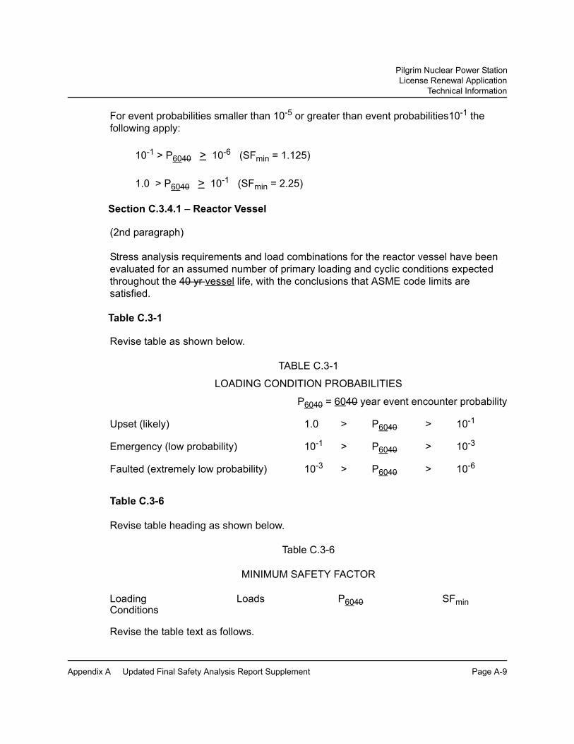
For event probabilities smaller than 10-5 or greater than event probabilities10-1 the following apply:
10-1 > P6040 > 10-6 (SFmin = 1.125)
1.0 > P6040 > 10-1 (SFmin = 2.25)
Section C.3.4.1 – Reactor Vessel
(2nd paragraph)
Stress analysis requirements and load combinations for the reactor vessel have been evaluated for an assumed number of primary loading and cyclic conditions expected throughout the 40 yr vessel life, with the conclusions that ASME code limits are satisfied.
Table C.3-1
Revise table as shown below.
TABLE C.3-1
LOADING CONDITION PROBABILITIES
P6040 = 6040 year event encounter probability
Upset (likely) 1.0 > P6040 > 10-1
Emergency (low probability) 10-1 > P6040 > 10-3
Faulted (extremely low probability) 10-3 > P6040 > 10-6
Table C.3-6
Revise table heading as shown below.
Table C.3-6
MINIMUM SAFETY FACTOR
Loading Loads P6040 SFminConditions
Revise the table text as follows.
Pilgrim Nuclear Power StationLicense Renewal Application
Technical Information
Appendix A Updated Final Safety Analysis Report Supplement Page A-10
The minimum safety factor decreases as the event probability diminishes and if the event is too improbable (incredible: P6040 < 10-6) then no safety factor is appropriate or required.
Table C.3-8
Revise table as shown below.
Pilgrim Nuclear Power StationLicense Renewal Application
Technical Information
Appendix A Updated Final Safety Analysis Report Supplement Page A-11
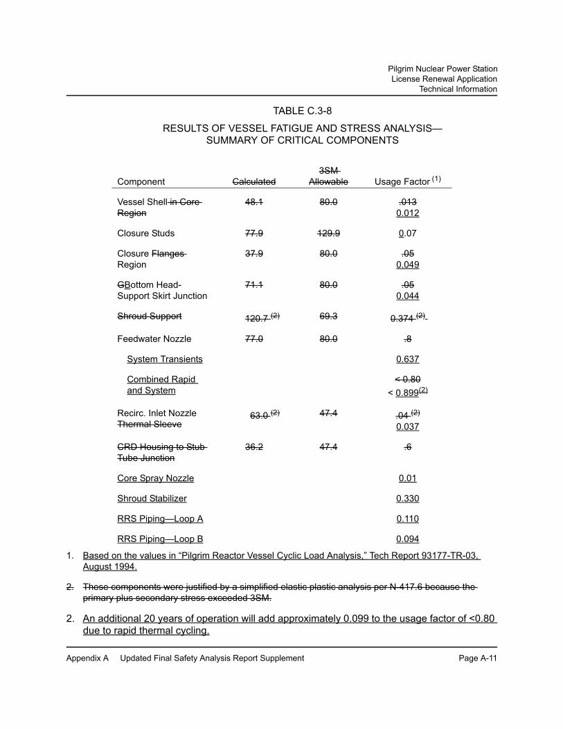
TABLE C.3-8
RESULTS OF VESSEL FATIGUE AND STRESS ANALYSIS— SUMMARY OF CRITICAL COMPONENTS
1. Based on the values in “Pilgrim Reactor Vessel Cyclic Load Analysis,” Tech Report 93177-TR-03, August 1994.
2. These components were justified by a simplified elastic plastic analysis per N-417.6 because the primary plus secondary stress exceeded 3SM.
2. An additional 20 years of operation will add approximately 0.099 to the usage factor of <0.80 due to rapid thermal cycling.
Component Calculated3SM
Allowable Usage Factor (1)
Vessel Shell in Core Region
48.1 80.0 .0130.012
Closure Studs 77.9 129.9 0.07
Closure Flanges Region
37.9 80.0 .050.049
GBottom Head-Support Skirt Junction
71.1 80.0 .050.044
Shroud Support 120.7 (2) 69.3 0.374 (2)
Feedwater Nozzle 77.0 80.0 .8
System Transients 0.637
Combined Rapid and System
< 0.80< 0.899(2)
Recirc. Inlet Nozzle Thermal Sleeve
63.0 (2) 47.4 .04 (2)
0.037
CRD Housing to Stub Tube Junction
36.2 47.4 .6
Core Spray Nozzle 0.01
Shroud Stabilizer 0.330
RRS Piping—Loop A 0.110
RRS Piping—Loop B 0.094

Pilgrim Nuclear Power StationLicense Renewal Application
Technical Information
Appendix A Updated Final Safety Analysis Report Supplement Page A-12
A.1.6 UFSAR Appendix M Changes
Section M.1, Introduction to the Report
(4th paragraph)
A series of exhibits are referenced in the Summary Section. These exhibits present the purchase specifications, inspection report, fabrication test program, summary of tensile tests of special steels, and earthquake analysis of the reactor pressure vessel. These exhibits support the statement made in the opening paragraph. Reactor vessel stresses and analyses are summarized in Section C.3.4.1 of Appendix C. Stress analysis requirements and load combinations for the reactor vessel have been evaluated for the primary loading and cyclic conditions expected throughout the 40 yr vessel life, with the conclusion that ASME code limits are satisfied.

Pilgrim Nuclear Power StationLicense Renewal Application
Technical Information
Appendix A Updated Final Safety Analysis Report Supplement Page A-13
A.2 NEW UFSAR SECTION
The following information will be integrated into the UFSAR to document aging management programs and activities credited in the PNPS license renewal review and time-limited aging analyses evaluated for the period of extended operation. References to other sections are to UFSAR sections, not to sections in the LRA.
A.2.0 Supplement for Renewed Operating License
The Pilgrim Nuclear Power Station license renewal application (Reference A.2-1) and information in subsequent related correspondence provided sufficient basis for the NRC to make the findings required by 10 CFR 54.29 (Final Safety Evaluation Report) (Reference A.2-2). As required by 10 CFR 54.21(d), this UFSAR supplement contains a summary description of the programs and activities for managing the effects of aging (Section A.2.1) and a description of the evaluation of time-limited aging analyses for the period of extended operation (Section A.2.2). The period of extended operation is the 20 years after the expiration date of the original operating license.
A.2.1 Aging Management Programs and Activities
The integrated plant assessment for license renewal identified aging management programs necessary to provide reasonable assurance that components within the scope of license renewal will continue to perform their intended functions consistent with the current licensing basis (CLB) for the period of extended operation. This section describes the aging management programs and activities required during the period of extended operation. All aging management programs will be implemented prior to entering the period of extended operation.
PNPS quality assurance (QA) procedures, review and approval processes, and administrative controls are implemented in accordance with the requirements of 10 CFR 50, Appendix B. The Entergy Quality Assurance Program applies to safety-related structures and components. Corrective actions and administrative (document) control for both safety-related and nonsafety-related structures and components are accomplished per the existing PNPS corrective action program and document control program and are applicable to all aging management programs and activities that will be required during the period of extended operation. The confirmation process is part of the corrective action program and includes reviews to assure that proposed actions are adequate, tracking and reporting of open corrective actions, and review of corrective action effectiveness. Any follow-up inspection required by the confirmation process is documented in accordance with the corrective action program.
A.2.1.1 Boraflex Monitoring Program
The Boraflex Monitoring Program assures that degradation of the Boraflex panels in the spent fuel racks does not compromise the criticality analysis in support of the design of the spent fuel storage racks. The program relies on (1) neutron attenuation testing, (2) determination of boron loss through correlation of silica levels in spent fuel pool

Pilgrim Nuclear Power StationLicense Renewal Application
Technical Information
Appendix A Updated Final Safety Analysis Report Supplement Page A-14
water samples and periodic areal density measurements, and (3) analysis of criticality to assure that the required 5% subcriticality margin is maintained.
A.2.1.2 Buried Piping and Tanks Inspection Program
The Buried Piping and Tanks Inspection Program includes (a) preventive measures to mitigate corrosion and (b) inspections to manage the effects of corrosion on the pressure-retaining capability of buried carbon steel, stainless steel, and titanium components. Preventive measures are in accordance with standard industry practice for maintaining external coatings and wrappings. Buried components are inspected when excavated during maintenance. If trending within the corrective action program identifies susceptible locations, the areas with a history of corrosion problems are evaluated for the need for additional inspection, alternate coating, or replacement.
A focused inspection will be performed within the first 10 years of the period of extended operation, unless an opportunistic inspection (or an inspection via a method that allows assessment of pipe condition without excavation) occurs within this ten-year period.
A.2.1.3 BWR CRD Return Line Nozzle Program
Under the BWR CRD Return Line Nozzle Program, PNPS has cut and capped the CRD return line nozzle to mitigate cracking and continues inservice inspection (ISI) examinations to monitor the effects of crack initiation and growth on the intended function of the control rod drive return line nozzle and cap. ISI examinations include ultrasonic inspection of the nozzle-to-vessel weld and ultrasonic inspection of the dissimilar metal weld overlay at the nozzle.
A.2.1.4 BWR Feedwater Nozzle Program
Under the BWR Feedwater Nozzle Program, PNPS has removed feedwater blend radii flaws, removed feedwater nozzle cladding, and installed a triple-sleeve-double-piston sparger to mitigate cracking. This program continues enhanced inservice inspection (ISI) of the feedwater nozzles in accordance with the requirements of ASME Section XI, Subsection IWB and the recommendation of General Electric (GE) NE-523-A71-0594 to monitor the effects of cracking on the intended function of the feedwater nozzles.
A.2.1.5 BWR Penetrations Program
The BWR Penetrations Program includes (a) inspection and flaw evaluation in conformance with the guidelines of staff-approved boiling water reactor vessel and internals project (BWRVIP) documents BWRVIP-27 and BWRVIP-49 and (b) monitoring and control of reactor coolant water chemistry in accordance with the guidelines of BWRVIP-130 to ensure the long-term integrity of vessel penetrations and nozzles.

Pilgrim Nuclear Power StationLicense Renewal Application
Technical Information
Appendix A Updated Final Safety Analysis Report Supplement Page A-15
A.2.1.6 BWR Stress Corrosion Cracking Program
The BWR Stress Corrosion Cracking Program includes (1) preventive measures to mitigate intergranular stress corrosion cracking (IGSCC), and (2) inspection and flaw evaluation to monitor IGSCC and its effects on reactor coolant pressure boundary components made of stainless steel or CASS.
PNPS has taken actions to prevent IGSCC and will continue to use materials resistant to IGSCC for component replacements and repairs following the recommendations delineated in NUREG-0313, Generic Letter 88-01, and the staff-approved BWRVIP-75 report. Inspection of piping identified in NRC Generic Letter 88-01 to detect and size cracks is performed in accordance with the staff positions on schedule, method, personnel qualification and sample expansion included in the generic letter and the staff-approved BWRVIP-75 report.
A.2.1.7 BWR Vessel ID Attachment Welds Program
The BWR Vessel ID Attachment Welds Program includes (1) inspection and flaw evaluation in accordance with the guidelines of staff-approved BWR Vessel and Internals Project (BWRVIP) BWRVIP-48, and (2) monitoring and control of reactor coolant water chemistry in accordance with the guidelines of BWRVIP-130 to ensure the long-term integrity and safe operation of reactor vessel inside diameter (ID) attachment welds and support pads.
A.2.1.8 BWR Vessel Internals Program
The BWR Vessel Internals Program includes (a) inspection, flaw evaluation, and repair in conformance with the applicable, staff-approved BWR Vessel and Internals Project (BWRVIP) documents, and (b) monitoring and control of reactor coolant water chemistry in accordance with the guidelines of BWRVIP-130 to ensure the long-term integrity of vessel internals components.
A.2.1.9 Containment Leak Rate Program
As described in 10 CFR 50, Appendix J, containment leak rate tests are required to assure that (a) leakage through primary reactor containment and systems and components penetrating primary containment shall not exceed allowable values specified in technical specifications or associated bases and (b) periodic surveillance of reactor containment penetrations and isolation valves is performed so that proper maintenance and repairs are made during the service life of containment, and systems and components penetrating primary containment. Corrective actions are taken if leakage rates exceed acceptance criteria.

Pilgrim Nuclear Power StationLicense Renewal Application
Technical Information
Appendix A Updated Final Safety Analysis Report Supplement Page A-16
A.2.1.10 Diesel Fuel Monitoring Program
The Diesel Fuel Monitoring Program entails sampling to ensure that adequate diesel fuel quality is maintained to prevent plugging of filters, fouling of injectors, and corrosion of fuel systems. Exposure to fuel oil contaminants such as water and microbiological organisms is minimized by periodic draining and cleaning of tanks and by verifying the quality of new oil before its introduction into the storage tanks.
A.2.1.11 Environmental Qualification (EQ) of Electric Components Program
The PNPS EQ of Electric Components program manages the effects of thermal, radiation, and cyclic aging through the use of aging evaluations based on 10 CFR 50.49(f) qualification methods. As required by 10 CFR 50.49, EQ components not qualified for the current license term are refurbished, replaced, or their qualification extended prior to reaching the aging limits established in the evaluations. Aging evaluations for EQ components are considered time-limited aging analyses (TLAAs) for license renewal.
A.2.1.12 Fatigue Monitoring Program
In order not to exceed design limits on fatigue usage, the Fatigue Monitoring Program tracks the number of critical thermal and pressure transients for selected reactor coolant system components. The program ensures the validity of analyses that explicitly assumed a fixed number of thermal and pressure fatigue transients by assuring that the actual effective number of transients does not exceed the assumed limit.
The transient cycles tracked by this program are referenced in Section 4.2.6.
A.2.1.13 Fire Protection Program
The Fire Protection Program includes a fire barrier inspection and a diesel-driven fire pump inspection. The fire barrier inspection requires periodic visual inspection of fire barrier penetration seals, fire barrier walls, ceilings, and floors, and periodic visual inspection and functional tests of fire rated doors to ensure that their operability is maintained. The diesel-driven fire pump inspection requires that the pump be periodically tested to ensure that the fuel supply line can perform its intended function. The program also includes periodic inspection and testing of the Halon fire suppression system.
Corrective actions, confirmation process, and administrative controls in accordance with the requirements of 10 CFR 50 Appendix B are applied to the Fire Protection Program.

Pilgrim Nuclear Power StationLicense Renewal Application
Technical Information
Appendix A Updated Final Safety Analysis Report Supplement Page A-17
A.2.1.14 Fire Water System Program
The Fire Water System Program applies to water-based fire protection systems that consist of sprinklers, nozzles, fittings, valves, hydrants, hose stations, standpipes, and aboveground and underground piping and components that are tested in accordance with applicable National Fire Protection Association (NFPA) codes and standards. Such testing assures functionality of systems. To determine if significant corrosion has occurred in water-based fire protection systems, periodic flushing, system performance testing and inspections are conducted. Also, many of these systems are normally maintained at required operating pressure and monitored such that leakage resulting in loss of system pressure is immediately detected and corrective actions initiated.
In addition, wall thickness evaluations of fire protection piping are periodically performed on system components using non-intrusive techniques (e.g., volumetric testing) to identify evidence of loss of material due to corrosion.
A sample of sprinkler heads will be inspected using the guidance of NFPA 25 (2002 Edition) Section 5.3.1.1.1, which states, “Where sprinklers have been in place for 50 years, they shall be replaced or representative samples from one or more sample areas shall be submitted to a recognized testing laboratory for field service testing.” This sampling will be repeated every 10 years after initial field service testing.
A.2.1.15 Flow-Accelerated Corrosion Program
The Flow-Accelerated Corrosion Program applies to safety-related and nonsafety-related carbon steel components in systems containing high-energy fluids carrying two-phase or single-phase high-energy fluid > 2% of plant operating time.
The program, based on EPRI recommendations for an effective flow-accelerated corrosion program, predicts, detects, and monitors FAC in plant piping and other pressure retaining components. This program includes (a) an evaluation to determine critical locations, (b) initial operational inspections to determine the extent of thinning at these locations, and (c) follow-up inspections to confirm predictions. The program specifies repair or replacement of components as necessary.
A.2.1.16 Heat Exchanger Monitoring Program
The Heat Exchanger Monitoring Program inspects heat exchangers for degradation. If degradation is found, then an evaluation is performed to evaluate its effects on the heat exchanger's design functions including its ability to withstand a seismic event.
Representative tubes within the population of heat exchangers are eddy current tested at a frequency determined by internal and external operating experience to ensure that effects of aging are identified prior to loss of intended function. Along with each eddy

Pilgrim Nuclear Power StationLicense Renewal Application
Technical Information
Appendix A Updated Final Safety Analysis Report Supplement Page A-18
current test, visual inspections are performed on accessible heat exchanger heads, covers and tube sheets to monitor surface condition for indications of loss of material. The population of heat exchangers includes the RHR heat exchangers, core spray pump motor thrust bearing lube oil coolers, HPCI gland seal condenser, HPCI turbine lube oil cooler, RCIC lube oil cooler, recirculation pump motor generator set fluid coupling oil and bearing coolers, CRD pump oil coolers, recirculation pump motor lube oil coolers, clean up recirculation pump lube oil coolers and stuffing box cooler, and EDG lube oil coolers.
A.2.1.17 Inservice Inspection - Containment Inservice Inspection (CII) Program
The Containment Inservice Inspection Program outlines the requirements for the inspection of Class MC pressure-retaining components (primary containment) and their integral attachments in accordance with the requirements of 10 CFR 50.55a(b)(2) and the 1998 Edition of ASME Section XI with 2000 Addenda, Inspection Program B.
The primary inspection method for the primary containment and its integral attachments is visual examination. Visual examinations are performed either directly or remotely with illumination and resolution suitable for the local environment to assess general conditions that may affect either the containment structural integrity or leak tightness of the pressure retaining component. The program includes augmented ultrasonic exams to measure wall thickness of the containment drywell structure.
A.2.1.18 Inservice Inspection – Inservice Inspection (ISI) Program
The ISI Program is based on ASME Inspection Program B (Section XI, IWA-2432), which has 10-year inspection intervals. Every 10 years the program is updated to the latest ASME Section XI code edition and addendum approved in 10 CFR 50.55a. On July 1, 2005 PNPS entered the fourth ISI interval. The code edition and addenda used for the fourth interval is the 1998 Edition with 2000 Addenda.
The program consists of periodic volumetric, surface, and visual examination of components and their supports for assessment, signs of degradation, flaw evaluation, and corrective actions.
A.2.1.19 Instrument Air Quality Program
The Instrument Air Quality Program ensures that instrument air supplied to components is maintained free of water and significant contaminants, thereby preserving an environment that is not conducive to loss of material. Dewpoint, particulate contamination, and hydrocarbon concentration are periodically checked to verify the instrument air quality is maintained.
Pilgrim Nuclear Power StationLicense Renewal Application
Technical Information
Appendix A Updated Final Safety Analysis Report Supplement Page A-19
A.2.1.20 Metal-Enclosed Bus Inspection Program
Under the Metal-Enclosed Bus Inspection Program, internal portions of the non-segregated phase bus which connects the 4.16kV switchgear (A3 through A6) are inspected for cracks, corrosion, foreign debris, excessive dust buildup, and evidence of water intrusion. Bus insulation is inspected for signs of embrittlement, cracking, melting, swelling, or discoloration, which may indicate overheating or aging degradation. Internal bus supports are inspected for structural integrity and signs of cracks. Since bolted connections are covered with heat shrink tape or insulating boots per manufacturer's recommendations, a sample of accessible bolted connections is visually inspected for insulation material surface anomalies. Enclosure assemblies are visually inspected for evidence of loss of material and, where applicable, enclosure assembly elastomers are visually inspected and manually flexed to manage cracking and change in material properties.
These inspections are performed at least once every 10 years.
A.2.1.21 Non-EQ Inaccessible Medium-Voltage Cable Program
In the Non-EQ Inaccessible Medium-Voltage Cable Program, in scope medium-voltage cables, not designed for, but exposed to significant moisture and voltage are tested at least once every ten years to provide an indication of the condition of the conductor insulation. The specific test performed is a proven test for detecting deterioration of the insulation system due to wetting, such as power factor, partial discharge, polarization index, or other testing that is state-of-the-art at the time the test is performed. Significant moisture is defined as periodic exposures that last more than a few days. Significant voltage exposure is defined as being subjected to system voltage for more than 25% of the time.
Inspections for water collection in cable manholes and conduit occur at least once every two years.
A.2.1.22 Non-EQ Instrumentation Circuits Test Review Program
Under the Non-EQ Instrumentation Circuits Test Review Program, calibration or surveillance results for non-EQ electrical cables in circuits with sensitive, high voltage, low-level signals; (i.e., neutron flux monitoring instrumentation); are reviewed. Most neutron flux monitoring system cables and connections are calibrated as part of the instrumentation loop calibration at the normal calibration frequency, which provides sufficient indication of the need for corrective actions based on acceptance criteria related to instrumentation loop performance. The review of calibration results is performed once every 10 years.

Pilgrim Nuclear Power StationLicense Renewal Application
Technical Information
Appendix A Updated Final Safety Analysis Report Supplement Page A-20
For neutron flux monitoring system cables that are disconnected during instrument calibrations, testing is performed at least once every 10 years using a proven method for detecting deterioration for the insulation system (such as insulation resistance tests, or time domain reflectometry).
A.2.1.23 Non-EQ Insulated Cables and Connections Program
The Non-EQ Insulated Cables and Connections Program provides reasonable assur-ance that intended functions of insulated cables and connections exposed to adverse localized environments caused by heat, radiation and moisture can be maintained con-sistent with the current licensing basis through the period of extended operation. An adverse localized environment is significantly more severe than the specified service condition for the insulated cable or connection.
A representative sample of accessible insulated cables and connections in adverse localized environments is visually inspected at least once every 10 years for cable and connection jacket surface anomalies such as embrittlement, discoloration, cracking or surface contamination.
A.2.1.24 Oil Analysis Program
The Oil Analysis Program maintains oil systems free of contaminants (primarily water and particulates) thereby preserving an environment that is not conducive to loss of material, cracking, or fouling. Activities include sampling and analysis of lubricating oil for detrimental contaminants, water, and particulates.
Sampling frequencies are based on vendor recommendations, accessibility during plant operation, equipment importance to plant operation, and previous test results.
A.2.1.25 One-Time Inspection Program
The elements of the One-Time Inspection Program include (a) determination of the sample size based on an assessment of materials of fabrication, environment, plausible aging effects, and operating experience; (b) identification of the inspection locations in the system or component based on the aging effect; (c) determination of the examination technique, including acceptance criteria that would be effective in managing the aging effect for which the component is examined; and (d) evaluation of the need for follow-up examinations to monitor the progression of any aging degradation.
A one-time inspection activity is used to verify the effectiveness of the water chemistry control programs by confirming that unacceptable cracking, loss of material, and fouling is not occurring on components within systems covered by water chemistry control programs [Sections A.2.1.36, A.2.1.37, and A.2.1.38].

Pilgrim Nuclear Power StationLicense Renewal Application
Technical Information
Appendix A Updated Final Safety Analysis Report Supplement Page A-21
One-time inspection activities on
• internal surfaces of buried carbon steel pipe on the standby gas treatment system discharge to the stack,
• internal surfaces of compressed air and EDG system components containing untreated air,
• internal surfaces of stainless steel radioactive waste and sanitary soiled waste and vent system components containing untreated water,
• small bore piping in the reactor coolant system and associated systems that form the reactor coolant pressure boundary,
• reactor vessel flange leak-off line, and • main steam flow restrictors
are used to confirm that loss of material, cracking, and reduction of fracture toughness, as applicable, are not occurring or are so insignificant that an aging management program is not warranted.
When evidence of an aging effect is revealed by a one-time inspection, routine evaluation of the inspection results will identify appropriate corrective actions.
A.2.1.26 Periodic Surveillance and Preventive Maintenance Program
The Periodic Surveillance and Preventive Maintenance Program includes periodic inspections and tests that manage aging effects not managed by other aging management programs. The preventive maintenance and surveillance testing activities are generally implemented through repetitive tasks or routine monitoring of plant operations.
Temperatures are monitored during periodic emergency diesel generator (EDG), station blackout diesel, and security diesel surveillance tests to verify that associated heat exchangers are capable of removing the required amount of heat, thereby managing fouling of the heat exchanger tubes.
Periodic inspections using visual or other non-destructive examination techniques verify that the following components are capable of performing their intended function.
• reactor building crane, rails, and girders• refueling platform carbon steel components• main stack components• standby liquid control system discharge accumulators• carbon steel piping in the waterline region of the torus• HPCI gland seal condenser blower and suction piping• RCIC steam supply and exhaust piping downstream of the strainers and steam
traps
Pilgrim Nuclear Power StationLicense Renewal Application
Technical Information
Appendix A Updated Final Safety Analysis Report Supplement Page A-22
• standby gas treatment system expansion joints, demister drain valves and demister drain piping
• drain lines from each reactor building auxiliary bay passing into the water trough in the torus
• clean-up recirculation pump P-204B stuffing box cooler• RBCCW copper alloy cooling coils• EDG, station blackout diesel, and security diesel intake air, air start, and exhaust
components• EDG, station blackout diesel, and security diesel jacket water radiators• security diesel oil cooler and aftercooler• area coolers VAC-210A/B, VAC-202A/B, and VAC-204A/B/C/D• VSF-103A/B, VAC-202A/B, VAC-204A/B/C/D, and EDG engine driven fan duct
flexible connections• condensate storage tanks• circulating water, potable & sanitary water, radioactive waste, sanitary soiled
waste & vent, plumbing and drains and screen wash system components• flex/expansion joints in the circulating water, HVAC/chilled water, and radioactive
waste systems
A.2.1.27 Reactor Head Closure Studs Program
The Reactor Head Closure Studs Program includes inservice inspection (ISI) in conformance with the requirements of the ASME Code, Section XI, Subsection IWB, and preventive measures (e.g. rust inhibitors, stable lubricants, appropriate materials) to mitigate cracking and loss of material of reactor head closure studs, nuts, washers, and bushings.
A.2.1.28 Reactor Vessel Surveillance Program
PNPS is a participant in the BWR vessel and internals project (BWRVIP) Integrated Surveillance Program (ISP) as incorporated into the plant Technical Specifications by License Amendment 209. The Reactor Vessel Surveillance Program monitors changes in the fracture toughness properties of ferritic materials in the reactor pressure vessel (RPV) beltline region. As BWRVIP-ISP capsule test reports become available for RPV materials representative of PNPS, the actual shift in the reference temperature for nil-ductility transition of the vessel material may be updated. In accordance with 10 CFR 50 Appendices G and H, PNPS reviews relevant test reports to assure compliance with fracture toughness requirements and P-T limits.
BWRVIP-116, “BWR Vessel and Internals Project Integrated Surveillance Program (ISP) Implementation for License Renewal,” describes the design and implementation of the ISP during the period of extended operation. BWRVIP-116 identifies additional capsules, their withdrawal schedule, and contingencies to ensure that the requirements of 10 CFR 50 Appendix H are met for the period of extended operation.

Pilgrim Nuclear Power StationLicense Renewal Application
Technical Information
Appendix A Updated Final Safety Analysis Report Supplement Page A-23
A.2.1.29 Selective Leaching Program
The Selective Leaching Program ensures the integrity of components made of cast iron, bronze, brass, and other alloys exposed to raw water, treated water, or groundwater that may lead to selective leaching. The program includes a one-time visual inspection and hardness measurement of selected components that may be susceptible to selective leaching to determine whether loss of material due to selective leaching is occurring, and whether the process will affect the ability of the components to perform their intended function for the period of extended operation.
A.2.1.30 Service Water Integrity Program
The Service Water Integrity Program relies on implementation of the recommendations of NRC GL 89-13 to ensure that the effects of aging on the salt service water (SSW) system are managed for the period of extended operation. The program includes component inspections for erosion, corrosion, and blockage and performance monitoring to verify the heat transfer capability of the safety-related heat exchangers cooled by SSW. Chemical treatment using biocides and chlorine and periodic cleaning and flushing of redundant or infrequently used loops are the methods used to control or prevent fouling within the heat exchangers and loss of material in SSW components.
A.2.1.31 Structures Monitoring - Masonry Wall Program
The objective of the Masonry Wall Program is to manage cracking so that the evaluation basis established for each masonry wall within the scope of license renewal remains valid through the period of extended operation.
The program includes all masonry walls identified as performing intended functions in accordance with 10 CFR 54.4. Included components are the 10 CFR 50.48-required masonry walls, radiation shielding masonry walls, masonry walls with the potential to affect safety-related components, and the torus compartment water trough.
Masonry walls are visually examined at a frequency selected to ensure there is no loss of intended function between inspections.
A.2.1.32 Structures Monitoring - Structures Monitoring Program
Structures monitoring is in accordance with 10 CFR 50.65 (Maintenance Rule) as addressed in Regulatory Guide 1.160 and NUMARC 93-01. Periodic inspections are used to monitor the condition of structures and structural components to ensure there is no loss of structure or structural component intended function.

Pilgrim Nuclear Power StationLicense Renewal Application
Technical Information
Appendix A Updated Final Safety Analysis Report Supplement Page A-24
A.2.1.33 Structures Monitoring - Water Control Structures Monitoring Program
The Water Control Structures Monitoring Program includes visual inspections to manage loss of material and loss of form for water-control structures (breakwaters, jetties, and revetments). The water-control structures are of rubble mound construction with the outer layer protected by heavy capstone. Parameters monitored include settlement (vertical displacement) and rock displacement. These parameters are consistent with those described in RG 1.127.
A.2.1.34 System Walkdown Program
The System Walkdown Program entails inspections of external surfaces of components subject to aging management review. The program is also credited with managing loss of material from internal surfaces, for situations in which internal and external material and environment combinations are the same such that external surface condition is representative of internal surface condition.
Surfaces that are inaccessible during plant operations are inspected during refueling outages. Surfaces are inspected at frequencies to provide reasonable assurance that effect of aging will be managed such that applicable components will perform their intended function during the period of extended operation.
A.2.1.35 Thermal Aging and Neutron Irradiation Embrittlement of Cast Austenitic Stainless Steel (CASS) Program
The purpose of the Thermal Aging and Neutron Irradiation Embrittlement of CASS Program is to assure that reduction of fracture toughness due to thermal aging and reduction of fracture toughness due to radiation embrittlement will not result in loss of intended function during the period of extended operation. This program evaluates CASS components in the reactor vessel internals and requires non-destructive examinations as appropriate.
A.2.1.36 Water Chemistry Control - Auxiliary Systems Program
The purpose of the Water Chemistry Control - Auxiliary Systems Program is to manage loss of material for components exposed to treated water.
Program activities include sampling and analysis of the stator cooling water system to minimize component exposure to aggressive environments.
A.2.1.37 Water Chemistry Control - BWR Program
The objective of the Water Chemistry Control - BWR Program is to manage aging effects caused by corrosion and cracking mechanisms. The program relies on monitoring and control of water chemistry based on EPRI Report 1008192 (BWRVIP-

Pilgrim Nuclear Power StationLicense Renewal Application
Technical Information
Appendix A Updated Final Safety Analysis Report Supplement Page A-25
130). BWRVIP-130 has three sets of guidelines: one for primary water, one for condensate and feedwater, and one for control rod drive (CRD) mechanism cooling water. EPRI guidelines in BWRVIP-130 also include recommendations for controlling water chemistry in the torus, condensate storage tank, demineralized water storage tanks, and spent fuel pool.
The Water Chemistry Control - BWR Program optimizes the primary water chemistry to minimize the potential for loss of material and cracking. This is accomplished by limiting the levels of contaminants in the RCS that could cause loss of material and cracking. Additionally, PNPS has instituted hydrogen water chemistry (HWC) to limit the potential for intergranular SCC (IGSCC) through the reduction of dissolved oxygen in the treated water.
A.2.1.38 Water Chemistry Control - Closed Cooling Water Program
The Water Chemistry Control - Closed Cooling Water Program includes preventive measures that manage loss of material, cracking, and fouling for components in closed cooling water systems (reactor building closed cooling water, turbine building closed cooling water, emergency diesel generator cooling water, station blackout diesel cooling water, security diesel generator cooling water, and plant heating). These chemistry activities provide for monitoring and controlling closed cooling water chemistry using PNPS procedures and processes based on EPRI guidance for closed cooling water chemistry.

Pilgrim Nuclear Power StationLicense Renewal Application
Technical Information
Appendix A Updated Final Safety Analysis Report Supplement Page A-26
A.2.2 Evaluation of Time-Limited Aging Analyses
In accordance with 10 CFR 54.21(c), an application for a renewed license requires an evaluation of time-limited aging analyses (TLAA) for the period of extended operation. The following TLAA have been identified and evaluated to meet this requirement.
A.2.2.1 Reactor Vessel Neutron Embrittlement
The reactor vessel neutron embrittlement TLAA will either remain valid for the period of extended operation (P-T limits) in accordance with 10 CFR 54.21(c)(1)(i) or have been projected to the end of the period of extended operation in accordance with 10 CFR 54.21(c)(1)(ii). Fifty-four EFPY would be the effective full power years at the end of the period of extended operation assuming an average capacity factor of 90% for 60 years.
A.2.2.1.1 Reactor Vessel Fluence
Calculated fluence is based on a time-limited assumption defined by the operating term. As such, fluence is the time-limited assumption for the time-limited aging analyses that evaluate reactor vessel embrittlement.
Fluence values were calculated using the RAMA fluence calculation method. The RAMA fluence method was developed for the Electric Power Research Institute, Inc. and the Boiling Water Reactor Vessel and Internals Project (BWRVIP) for the purpose of calculating neutron fluence in boiling water reactor components. This method has been approved by the NRC (Reference A.2-9) for application in accordance with Regulatory Guide 1.190.
A.2.2.1.2 Pressure-Temperature Limits
The P-T limits were derived from calculations made in accordance with the guidance of ASME Appendix G, as modified by Code Cases N-588 and N-640, ASTM Standards, 10 CFR 50 Appendices G and H, Regulatory Guide 1.99 Revision 2, and Generic Letter 88-11.
The fluence calculations performed in accordance with RG 1.190 confirm that the fluence for 54 EFPY is less than the fluence used to calculate the P-T limits. The existing Technical Specification P-T limits remain valid for the period of extended operation in accordance with 10 CFR 54.21(c)(1)(i).
A.2.2.1.3 Charpy Upper-Shelf Energy
The predictions for percent drop in CVUSE at 54 EFPY are based on chemistry data and unirradiated CVUSE data submitted to the NRC in the PNPS response to GL 92-01, and ¼T fluence values.
Pilgrim Nuclear Power StationLicense Renewal Application
Technical Information
Appendix A Updated Final Safety Analysis Report Supplement Page A-27
The 54 EFPY CVUSE values were calculated using Regulatory Guide 1.99, Position 1, Figure 2; specifically, the formula for the lines was used to calculate the percent drop in CVUSE.
All CVUSE values are predicted to remain well above the requirement of 50 ft-lbs during the period of extended operation. As such, this TLAA has been projected to the end of the period of extended operation in accordance with 10 CFR 54.21(c)(1)(ii).
A.2.2.1.4 Adjusted Reference Temperature
The PNPS reactor vessel was designed for a 40-year life with an assumed exposure of less than 1019 nvt of neutrons with energies exceeding 1 MeV. After approximately 4.17 EFPY, the first surveillance capsule was withdrawn from the vessel and tested. The capsule test report concludes that the shift in RTNDT and upper shelf energy over 32 EFPY will be within 10 CFR 50 Appendix G guidelines.
PNPS has projected values for RTNDT and adjusted reference temperature (ART) at 54 EFPY using the methodology of Regulatory Guide 1.99. These values were calculated using the chemistry data, margin values, initial RTNDT values, and chemistry factors (CFs) contained in the PNPS response to GL 92-01 and other licensing correspondence (Reference A.2-10). New fluence factors (FFs) were calculated using the expression in Regulatory Guide 1.99, Revision 2, Equation 2 using 54 EFPY fluence values.
The RTNDT TLAA has been projected through the period of extended operation, with acceptable results, in accordance with 10 CFR 54.21(c)(1)(ii).
A.2.2.1.5 Reactor Vessel Circumferential Weld Inspection Relief
Relief from reactor vessel circumferential weld examination requirements under Generic Letter 98-05 is based on assessments indicating an acceptable probability of failure per reactor operating year. The analysis is based on reactor vessel metallurgical conditions as well as flaw indication sizes and frequencies of occurrence that are expected at the end of a licensed operating period.
PNPS received NRC approval for this relief for the remainder of the original 40-year license term (Reference A.2-3). The basis for this relief request is an analysis that satisfied the limiting conditional failure probability for the circumferential welds at the expiration of the current license, based on the NRC SERs for BWRVIP-05 (Reference A.2-6) and BWRVIP-74 (Reference A.2-11) and the extent of neutron embrittlement.
The chemistry composition and chemistry factor values for PNPS are slightly higher than those used in the NRC analysis; however, the 54 EFPY fluence value is

Pilgrim Nuclear Power StationLicense Renewal Application
Technical Information
Appendix A Updated Final Safety Analysis Report Supplement Page A-28
considerably lower than the corresponding 64 EFPY generic value. As a result, the shift in reference temperature is lower than the 64 EFPY shift in the NRC analysis. In addition, the unirradiated reference temperature of the PNPS material is lower than the initial value assumed in the NRC analysis. The combination of a lower initial reference temperature (RTNDT(U)) and a lower shift (RTNDT w/o margin) yields an adjusted reference temperature that is considerably lower than the NRC mean analysis value. Therefore, this TLAA has been projected to the end of the period of extended operation in accordance with 10 CFR 54.21(c)(1)(ii).
A.2.2.1.6 Reactor Vessel Axial Weld Failure Probability
The BWRVIP recommendations for inspection of reactor vessel shell welds (BWRVIP-05, Reference A.2-4) are based on generic analyses supporting an NRC SER (References A.2-5, A.2-6). The generic-plant axial weld failure rate is no more than 5 x 10⁻⁶ per reactor year as calculated in the BWRVIP-74 SER (Reference A.2-11). BWRVIP-05 showed that this axial weld failure rate is orders of magnitude greater than the 40-year end-of-life circumferential weld failure probability, and used this analysis to justify relief from inspection of the circumferential welds as described above.
The basis for this relief request was a plant specific analysis that showed the limiting conditional failure probability for the PNPS circumferential welds at the end of the original operating term were less than the values calculated in the BWRVIP-05 SER. The BWRVIP-05 SER concluded that the reactor vessel failure frequency due to failure of the limiting axial welds in the BWR fleet at the end of 40 years of operation is less than 5x10⁻⁶ per reactor year. This failure frequency is dependent upon given assumptions of flaw density, distribution, and location. The failure frequency also assumes that “essentially 100%” of the reactor vessel axial welds will be inspected.
The BWRVIP-74 SER states it is acceptable to show that the mean RTNDT of the limiting beltline axial weld at the end of the period of extended operation is less than the limiting value given in the SERs for BWRVIP-74 and BWRVIP-05. The projected 54 EFPY mean RTNDT values for PNPS are less than the limiting 64 EFPY RTNDT in the analysis performed by the NRC staff (Table 2.6-5 of the BWRVIP-05 SER). As such, this TLAA has been projected to the end of the period of extended operation in accordance with 10 CFR 54.21(c)(1)(ii).
A.2.2.2 Metal Fatigue
A.2.2.2.1 Class 1 Metal Fatigue
Class 1 components evaluated for fatigue and flaw growth include the reactor pressure vessel (RPV) and appurtenances, certain reactor vessel internals, the reactor recirculation system (RRS), and the reactor coolant system (RCS) pressure

Pilgrim Nuclear Power StationLicense Renewal Application
Technical Information
Appendix A Updated Final Safety Analysis Report Supplement Page A-29
boundary. The PNPS Class 1 systems include components within the ASME Section XI, IWB inspection boundary.
The design of the reactor vessel internals is in accordance with the intent of ASME Section III. A review of design basis documents reveals that the only reactor vessel internals components for which there is a fatigue evaluation are the core shroud tie rods (stabilizer), the result of a repair to structurally replace circumferential shroud welds.
The PNPS fatigue monitoring program will assure that the allowed number of transient cycles is not exceeded. The program requires corrective action if transient cycle limits are approached. Consequently, the TLAA (fatigue analyses) based on those transients will remain valid for the period of extended operation in accordance with 10 CFR 54.21(c)(1)(i) or the effects of aging on the intended function(s) will be adequately managed for the period of extended operation in accordance with 10 CFR 54.21(c)(1)(iii).
A.2.2.2.2 Non-Class 1 Metal Fatigue
For non-Class 1 components identified as subject to cracking due to fatigue, a review of system operating characteristics was conducted to determine the approximate frequency of any significant thermal cycling. If the number of equivalent full temperature cycles is below the limit used for the original design (usually 7000 cycles), the component is suitable for extended operation. If the number of equivalent full temperature cycles exceeds the limit, evaluation of the individual stress calculations require evaluation. No components were identified with projected cycles exceeding 7000. Therefore, the TLAA for non-Class 1 piping and components remain valid for the period of extended operation in accordance with 10 CFR 54.21(c)(i).
A.2.2.2.3 Environmental Effects on Fatigue
The effects of reactor water environment on fatigue were evaluated for license renewal. Projected cumulative usage factors (CUFs) were calculated for the limiting locations identified in NUREG/CR-6260. Several locations may exceed a CUF of 1.0 with consideration of environmental effects during the period of extended operation. For these locations, prior to the period of extended operation, PNPS will (1) refine the fatigue analysis to lower the predicted CUF to less than 1.0; (2) manage fatigue at the affected locations with an inspection program that has been reviewed and approved by the NRC (e.g., periodic non-destructive examination of the affected locations at inspection intervals to be determined by a method acceptable to the NRC); or (3) repair or replace the affected locations.

Pilgrim Nuclear Power StationLicense Renewal Application
Technical Information
Appendix A Updated Final Safety Analysis Report Supplement Page A-30
A.2.2.3 Environmental Qualification of Electrical Components
The PNPS EQ Program implements the requirements of 10 CFR 50.49 (as further defined by the Division of Operating Reactors Guidelines, NUREG-0588, and Reg. Guide 1.89). The program requires action before individual components exceed their qualified life. In accordance with 10 CFR 54.21(c)(1)(iii), implementation of the EQ Program provides reasonable assurance that the effects of aging on components associated with EQ TLAAs will be adequately managed such that the intended functions can be maintained for the period of extended operation.
A.2.2.4 Fatigue of Primary Containment, Attached Piping, and Components
In conjunction with the Mark I Containment Long-Term Program, the torus and attached piping systems were analyzed for fatigue due to mechanical loadings as well as thermal and anchor motion. This analysis was based on assumptions of the number of SRV actuations, operating basis earthquakes, and accident conditions during the life of the plant.
The fatigue usage calculated for PNPS is zero. However, the analysis considered all BWR plants which utilize the Mark I containment design. The analysis concluded that for all plants and piping systems considered, the fatigue usage factor for an assumed 40-year plant life was less than 0.5. Extending plant life by an additional 20 years would produce a usage factor below 0.75. Since this is less than 1.0, the fatigue criteria are satisfied. This TLAA has been projected through the period of extended operation in accordance with 10 CFR 54.21(c)(1)(ii).
A.2.2.5 Vessel ID Attachment Welds Fatigue Analysis
The BWRVIP-48 fatigue analyses for various configurations of different vessel ID bracket attachments are considered TLAA. The PNPS bracket configurations were included in the analysis. Analysis of fatigue for 60 years showed that no CUFs are above 0.4. This analysis remains valid for the period of extended operation in accordance with 10 CFR 54.21(c)(1)(i).
A.2.2.6 Instrument Penetrations Fatigue Analysis
The BWRVIP-49 fatigue analysis of several configurations of instrumentation penetrations, including the PNPS configuration, is considered a TLAA. Analysis of fatigue for 60 years showed that all CUFs are below 0.4. This analysis remains valid for the period of extended operation in accordance with 10 CFR 54.21(c)(1)(i).

Pilgrim Nuclear Power StationLicense Renewal Application
Technical Information
Appendix A Updated Final Safety Analysis Report Supplement Page A-31
A.2.3 References
A.2-1 PNPS License Renewal Application
A.2-2 (NRC SER for PNPS License Renewal - later)
A.2-3 Boska, J. (NRC), to M. Bellamy (ENGC), “Pilgrim Nuclear Power Station—Pilgrim Relief Request No. 28, Relief from ASME Code, Section XI, Examinations of Reactor Pressure Vessel Circumferential Shell Welds (TAC No. MB6074),” letter dated April 11, 2003.
A.2-4 BWRVIP-05, EPRI Report TR-105697, “BWR Vessel and Internals Project, BWR Reactor Pressure Vessel Shell Weld Inspection Recommendations (BWRVIP-05),” for the Boiling Water Reactor Owners Group (Proprietary), September 28, 1995, with supplementing letters of June 24 and October 29, 1996; May 16, June 4, June 13, and December 18, 1997; and January 13, 1998.
A.2-5 Lainas, G. C. (NRC), to C. Terry (Niagara Mohawk Power Company, BWRVIP Chairman), BWRVIP-05 SER (Final), Final Safety Evaluation of the BWRVIP Vessel and Internals Project BWRVIP-05 Report (TAC No. M93925), letter dated July 28, 1998.
A.2-6 Strosnider, J. R., Jr., (NRC) to C. Terry (BWRVIP Chairman), BWRVIP-05 SER, Supplement to Final Safety Evaluation of the BWRVIP Vessel and Internals Project BWRVIP-05 Report (TAC No. MA3395), letter dated March 7, 2000.
A.2-7 Riggs, W. J. (ENGC) to NRC, “Amendment 01-01 to the Third Ten-Year Interval Inservice Inspection Program,” letter dated November 20, 2001.
A.2-8 Milano, P. D. (NRC), to E. T. Boulette (BECo), “Evaluation of the Third Ten-Year Interval Inspection Program Plan, and Associated Requests for Relief for Pilgrim Nuclear Power Station (TAC No. M93398),” letter dated March 20, 1997.
A.2-9 Bateman, W. H. (NRC), to Eaton, W. (BWRVIP), "Safety Evaluation of Proprietary EPRI Reports BWRVIP-114, -115, -117, and -121 and TWE-PSE-001-R-001," letter dated May 13, 2005.
A.2-10 Bellamy, M. (ENGC), to Document Control Desk (NRC), “Additional Information Related to Pilgrim Technical Specification Change Concerning Pressure-Temperature Limit Curves of Figure 3.6.1.2 and 3,” letter 2.01.014 dated January 30, 2001.
A.2-11 Grimes, C. I. (NRC), to C. Terry (BWRVIP Chairman), Acceptance for referencing of EPRI Proprietary Report TR-113596, "BWR Vessel and Internals Project, BWR Reactor Vessel Inspection and Flaw Evaluation Guidelines (BWRVIP-74) and Appendix A, 'Demonstration of Compliance with the Technical Information requirements of the License Renewal Rule (10CRF54.21)', letter dated October 18, 2001.