appendix assemblers, linkers, and the spim simulatorhomes.di.unimi.it/~pedersini/aer/spim.pdf ·...
TRANSCRIPT
A
A P P E N D I XFear of serious injury cannot alojustify suppression of free speechand assembly.Louis BrandeisWhitney v. California, 1927
Copyright 1998 Morgan Kaufmann PublNo portion of this material may be repro
Assemblers,Linkers,and the SPIM Simulator
James R. LarusComputer Sciences DepartmentUniversity of Wisconsin–Madison
ne
ishers. duced without permission of the publsiher.
A.1 Introduction
A-3
A.2 Assemblers
A-10
A.3 Linkers
A-17
A.4 Loading
A-19
A.5 Memory Usage
A-20
A.6 Procedure Call Convention
A-22
A.7 Exceptions and Interrupts
A-32
A.8 Input and Output
A-36
A.9 SPIM
A-38
A.10 MIPS R2000 Assembly Language
A-49
A.11 Concluding Remarks
A-75
A.12 Key Terms
A-76
A.13 Exercises
A-76
Encoding instructions as binary numbers is natural and efficient for comput-ers. Humans, however, have a great deal of difficulty understanding andmanipulating these numbers. People read and write symbols (words) muchbetter than long sequences of digits. Chapter 3 showed that we need notchoose between numbers and words because computer instructions can berepresented in many ways. Humans can write and read symbols, and com-puters can execute the equivalent binary numbers. This appendix describesthe process by which a human-readable program is translated into a form thata computer can execute, provides a few hints about writing assembly pro-grams, and explains how to run these programs on SPIM, a simulator thatexecutes MIPS programs. Unix, Windows, and DOS versions of the SPIM sim-ulator are available through www.mkp.com/cod2e.htm.
Assembly language is the symbolic representation of a computer’s binary en-coding—machine language. Assembly language is more readable than machinelanguage because it uses symbols instead of bits. The symbols in assembly lan-guage name commonly occurring bit patterns, such as opcodes and registerspecifiers, so people can read and remember them. In addition, assembly lan-guage permits programmers to use labels to identify and name particular mem-ory words that hold instructions or data.
A.1 Introduction A.1

A-4
Appendix A Assemblers, Linkers, and the SPIM Simulator
A tool called an assembler translates assembly language into binary instruc-tions. Assemblers provide a friendlier representation than a computer’s 0s and1s that simplifies writing and reading programs. Symbolic names for opera-tions and locations are one facet of this representation. Another facet is pro-gramming facilities that increase a program’s clarity. For example, macros,discussed in section A.2, enable a programmer to extend the assembly lan-guage by defining new operations.
An assembler reads a single assembly language source file and produces anobject file containing machine instructions and bookkeeping information thathelps combine several object files into a program. Figure A.1 illustrates how aprogram is built. Most programs consist of several files—also called modules—that are written, compiled, and assembled independently. A program may alsouse prewritten routines supplied in a program library. A module typically con-tains references to subroutines and data defined in other modules and in librar-ies. The code in a module cannot be executed when it contains unresolvedreferences to labels in other object files or libraries. Another tool, called a linker,combines a collection of object and library files into an executable file, which acomputer can run.
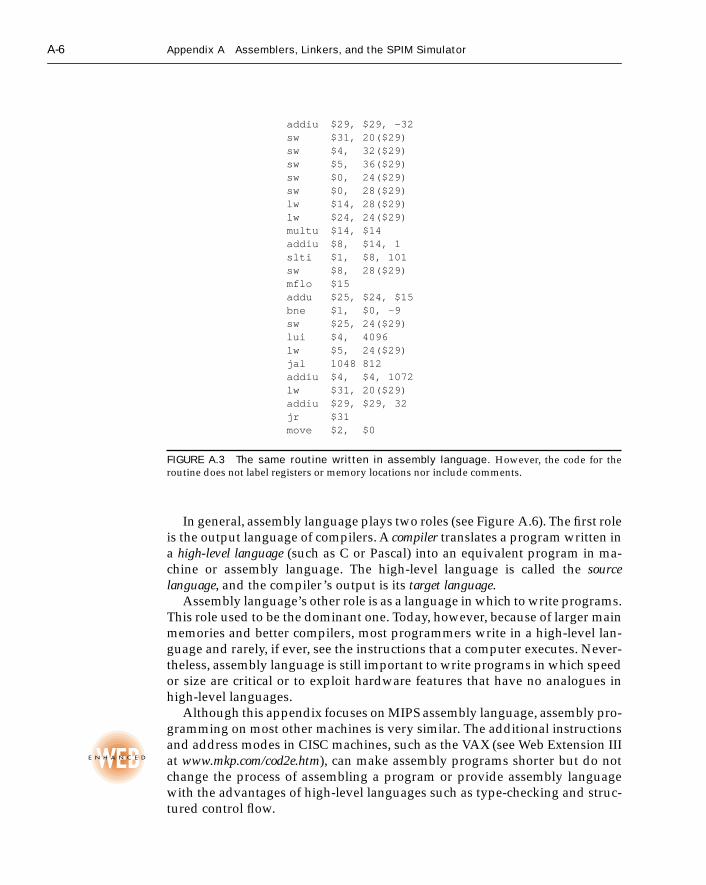
To see the advantage of assembly language, consider the following se-quence of figures, all of which contain a short subroutine that computes andprints the sum of the squares of integers from 0 to 100. Figure A.2 shows themachine language that a MIPS computer executes. With considerable effort,you could use the opcode and instruction format tables in Chapters 3 and 4 totranslate the instructions into a symbolic program similar to Figure A.3. Thisform of the routine is much easier to read because operations and operands arewritten with symbols, rather than with bit patterns. However, this assembly
FIGURE A.1 The process that produces an executable file. An assembler translates a file ofassembly language into an object file, which is linked with other files and libraries into an executablefile.
Objectfile
Sourcefile Assembler
LinkerAssembler
AssemblerProgramlibrary
Objectfile
Objectfile
Sourcefile
Sourcefile
Executablefile

A.1 Introduction
A-5
language is still difficult to follow because memory locations are named bytheir address, rather than by a symbolic label.
Figure A.4 shows assembly language that labels memory addresses withmnemonic names. Most programmers prefer to read and write this form.Names that begin with a period, for example .data and .globl, are assemblerdirectives that tell the assembler how to translate a program but do not producemachine instructions. Names followed by a colon, such as str or main, are la-bels that name the next memory location. This program is as readable as mostassembly language programs (except for a glaring lack of comments), but it isstill difficult to follow because many simple operations are required to accom-plish simple tasks and because assembly language’s lack of control flow con-structs provides few hints about the program’s operation.
By contrast, the C routine in Figure A.5 is both shorter and clearer sincevariables have mnemonic names and the loop is explicit rather than construct-ed with branches. (If you are unfamiliar with C, you may wish to look at WebExtension II at www.mkp.com/cod2e.htm.) In fact, the C routine is the only onethat we wrote. The other forms of the program were produced by a C compilerand assembler.
001001111011110111111111111000001010111110111111000000000001010010101111101001000000000000100000101011111010010100000000001001001010111110100000000000000001100010101111101000000000000000011100100011111010111000000000000111001000111110111000000000000001100000000001110011100000000000011001001001011100100000000000000000010010100100000001000000000110010110101111101010000000000000011100000000000000000001111000000100100000001100001111110010000010000100010100001000001111111111110111101011111011100100000000000110000011110000000100000100000000000010001111101001010000000000011000000011000001000000000000111011000010010010000100000001000011000010001111101111110000000000010100001001111011110100000000001000000000001111100000000000000000100000000000000000000001000000100001
FIGURE A.2 MIPS machine language code for a routine to compute and print the sum ofthe squares of integers between 0 and 100.
A-6
Appendix A Assemblers, Linkers, and the SPIM Simulator
In general, assembly language plays two roles (see Figure A.6). The first roleis the output language of compilers. A compiler translates a program written ina high-level language (such as C or Pascal) into an equivalent program in ma-chine or assembly language. The high-level language is called the sourcelanguage, and the compiler’s output is its target language.
Assembly language’s other role is as a language in which to write programs.This role used to be the dominant one. Today, however, because of larger mainmemories and better compilers, most programmers write in a high-level lan-guage and rarely, if ever, see the instructions that a computer executes. Never-theless, assembly language is still important to write programs in which speedor size are critical or to exploit hardware features that have no analogues inhigh-level languages.
Although this appendix focuses on MIPS assembly language, assembly pro-gramming on most other machines is very similar. The additional instructionsand address modes in CISC machines, such as the VAX (see Web Extension IIIat www.mkp.com/cod2e.htm), can make assembly programs shorter but do notchange the process of assembling a program or provide assembly languagewith the advantages of high-level languages such as type-checking and struc-tured control flow.
addiu $29, $29, -32sw $31, 20($29)sw $4, 32($29)sw $5, 36($29)sw $0, 24($29)sw $0, 28($29)lw $14, 28($29)lw $24, 24($29)multu $14, $14addiu $8, $14, 1slti $1, $8, 101sw $8, 28($29)mflo $15addu $25, $24, $15bne $1, $0, -9sw $25, 24($29)lui $4, 4096lw $5, 24($29)jal 1048 812addiu $4, $4, 1072lw $31, 20($29)addiu $29, $29, 32jr $31move $2, $0
FIGURE A.3 The same routine written in assembly language. However, the code for theroutine does not label registers or memory locations nor include comments.

A.1 Introduction
A-7
When to Use Assembly LanguageThe primary reason to program in assembly language, as opposed to an avail-able high-level language, is that the speed or size of a program is criticallyimportant. For example, consider a computer that controls a piece of machin-ery, such as a car’s brakes. A computer that is incorporated in another device,such as a car, is called an embedded computer. This type of computer needs torespond rapidly and predictably to events in the outside world. Because a
.text
.align 2
.globl mainmain:
subu $sp, $sp, 32sw $ra, 20($sp)sd $a0, 32($sp)sw $0, 24($sp)sw $0, 28($sp)
loop:lw $t6, 28($sp)mul $t7, $t6, $t6lw $t8, 24($sp)addu $t9, $t8, $t7sw $t9, 24($sp)addu $t0, $t6, 1sw $t0, 28($sp)ble $t0, 100, loopla $a0, strlw $a1, 24($sp)jal printfmove $v0, $0lw $ra, 20($sp)addu $sp, $sp, 32j $ra
.data
.align 0str:
.asciiz "The sum from 0 .. 100 is %d\n"
FIGURE A.4 The same routine written in assembly language with labels, but no com-ments. The commands that start with periods are assembler directives (see pages A-51–A-53)..text indicates that succeeding lines contain instructions. .data indicates that they containdata. .align n indicates that the items on the succeeding lines should be aligned on a 2n byteboundary. Hence, .align 2 means the next item should be on a word boundary. .globl maindeclares that main is a global symbol that should be visible to code stored in other files. Finally,.asciiz stores a null-terminated string in memory.

A-8
Appendix A Assemblers, Linkers, and the SPIM Simulator
compiler introduces uncertainty about the time cost of operations, program-mers may find it difficult to ensure that a high-level language programresponds within a definite time interval—say, 1 millisecond after a sensordetects that a tire is skidding. An assembly language programmer, on theother hand, has tight control over which instructions execute. In addition, inembedded applications, reducing a program’s size, so that it fits in fewermemory chips, reduces the cost of the embedded computer.
A hybrid approach, in which most of a program is written in a high-levellanguage and time-critical sections are written in assembly language, builds onthe strengths of both languages. Programs typically spend most of their timeexecuting a small fraction of the program’s source code. This observation isjust the principle of locality that underlies caches (see section 7.2 in Chapter 7).
Program profiling measures where a program spends its time and can findthe time-critical parts of a program. In many cases, this portion of the programcan be made faster with better data structures or algorithms. Sometimes, how-ever, significant performance improvements only come from recoding a criti-cal portion of a program in assembly language.
#include <stdio.h>
intmain (int argc, char *argv[]){ int i; int sum = 0;
for (i = 0; i <= 100; i = i + 1) sum = sum + i * i; printf ("The sum from 0 .. 100 is %d\n", sum);}
FIGURE A.5 The routine written in the C programming language.
FIGURE A.6 Assembly language either is written by a programmer or is the output of a com-piler.
LinkerCompilerProgram Assembler Computer
High-level language program
Assembly language program
A.1 Introduction
A-9
This improvement is not necessarily an indication that the high-levellanguage’s compiler has failed. Compilers typically are better than program-mers at producing uniformly high-quality machine code across an entire pro-gram. Programmers, however, understand a program’s algorithms andbehavior at a deeper level than a compiler and can expend considerable effortand ingenuity improving small sections of the program. In particular, pro-grammers often consider several procedures simultaneously while writingtheir code. Compilers typically compile each procedure in isolation and mustfollow strict conventions governing the use of registers at procedure bound-aries. By retaining commonly used values in registers, even across procedureboundaries, programmers can make a program run faster.
Another major advantage of assembly language is the ability to exploit spe-cialized instructions, for example, string copy or pattern-matching instruc-tions. Compilers, in most cases, cannot determine that a program loop can bereplaced by a single instruction. However, the programmer who wrote theloop can replace it easily with a single instruction.
In the future, a programmer’s advantage over a compiler is likely to becomeincreasingly difficult to maintain as compilation techniques improve andmachines’ pipelines increase in complexity (Chapter 6).
The final reason to use assembly language is that no high-level language isavailable on a particular computer. Many older or specialized computers donot have a compiler, so a programmer’s only alternative is assembly language.
Drawbacks of Assembly LanguageAssembly language has many disadvantages that strongly argue against itswidespread use. Perhaps its major disadvantage is that programs written inassembly language are inherently machine-specific and must be totallyrewritten to run on another computer architecture. The rapid evolution ofcomputers discussed in Chapter 1 means that architectures become obsolete.An assembly language program remains tightly bound to its original archi-tecture, even after the computer is eclipsed by new, faster, and more cost-effective machines.
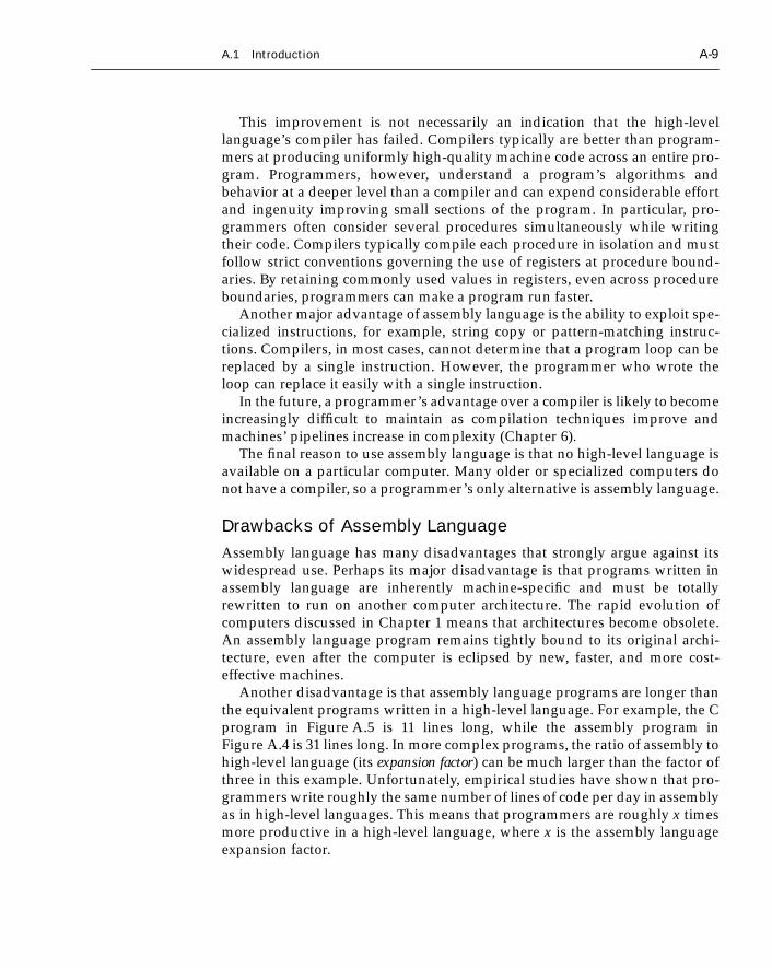
Another disadvantage is that assembly language programs are longer thanthe equivalent programs written in a high-level language. For example, the Cprogram in Figure A.5 is 11 lines long, while the assembly program inFigure A.4 is 31 lines long. In more complex programs, the ratio of assembly tohigh-level language (its expansion factor) can be much larger than the factor ofthree in this example. Unfortunately, empirical studies have shown that pro-grammers write roughly the same number of lines of code per day in assemblyas in high-level languages. This means that programmers are roughly x timesmore productive in a high-level language, where x is the assembly languageexpansion factor.

A-10
Appendix A Assemblers, Linkers, and the SPIM Simulator
To compound the problem, longer programs are more difficult to read andunderstand and they contain more bugs. Assembly language exacerbates theproblem because of its complete lack of structure. Common programming id-ioms, such as if-then statements and loops, must be built from branches andjumps. The resulting programs are hard to read because the reader must recon-struct every higher-level construct from its pieces and each instance of a state-ment may be slightly different. For example, look at Figure A.4 and answerthese questions: What type of loop is used? What are its lower and upperbounds?
Elaboration: Compilers can produce machine language directly instead of relying onan assembler. These compilers typically execute much faster than those that invoke anassembler as part of compilation. However, a compiler that generates machine lan-guage must per form many tasks that an assembler normally handles, such as resolvingaddresses and encoding instructions as binary numbers. The trade-off is between com-pilation speed and compiler simplicity.
Elaboration: Despite these considerations, some embedded applications are writtenin a high-level language. Many of these applications are large and complex programsthat must be extremely reliable. Assembly language programs are longer and more diffi-cult to write and read than high-level language programs. This greatly increases the costof writing an assembly language program and makes it extremely difficult to verify thecorrectness of this type of program. In fact, these considerations led the Department ofDefense, which pays for many complex embedded systems, to develop Ada, a new high-level language for writing embedded systems.
An assembler translates a file of assembly language statements into a file ofbinary machine instructions and binary data. The translation process has twomajor parts. The first step is to find memory locations with labels so the rela-tionship between symbolic names and addresses is known when instructionsare translated. The second step is to translate each assembly statement bycombining the numeric equivalents of opcodes, register specifiers, and labelsinto a legal instruction. As shown in Figure A.1, the assembler produces anoutput file, called an object file, which contains the machine instructions, data,and bookkeeping information.
A.2 Assemblers A.2
A.2 Assemblers
A-11
An object file typically cannot be executed because it references proceduresor data in other files. A label is external (also called global) if the labeled objectcan be referenced from files other than the one in which it is defined. A label islocal if the object can be used only within the file in which it is defined. In mostassemblers, labels are local by default and must be explicitly declared global.Subroutines and global variables require external labels since they are refer-enced from many files in a program. Local labels hide names that should notbe visible to other modules—for example, static functions in C, which can onlybe called by other functions in the same file. In addition, compiler-generatednames—for example, a name for the instruction at the beginning of a loop—are local so the compiler need not produce unique names in every file.
Since the assembler processes each file in a program individually and in iso-lation, it only knows the addresses of local labels. The assembler depends onanother tool, the linker, to combine a collection of object files and libraries intoan executable file by resolving external labels. The assembler assists the linkerby providing lists of labels and unresolved references.
However, even local labels present an interesting challenge to an assembler.Unlike names in most high-level languages, assembly labels may be used be-fore they are defined. In the example, in Figure A.4, the label str is used by thela instruction before it is defined. The possibility of a forward reference, like thisone, forces an assembler to translate a program in two steps: first find all labelsand then produce instructions. In the example, when the assembler sees the lainstruction, it does not know where the word labeled str is located or evenwhether str labels an instruction or datum.
Local and Global Labels
Consider the program in Figure A.4 on page A-7. The subroutine has anexternal (global) label main. It also contains two local labels—loop andstr—that are only visible with this assembly language file. Finally, theroutine also contains an unresolved reference to an external label printf,which is the library routine that prints values. Which labels in Figure A.4could be referenced from another file?
Only global labels are visible outside of a file, so the only label that couldbe referenced from another file is main.
Example
Answer

A-12 Appendix A Assemblers, Linkers, and the SPIM Simulator
An assembler’s first pass reads each line of an assembly file and breaks itinto its component pieces. These pieces, which are called lexemes, are individ-ual words, numbers, and punctuation characters. For example, the line
ble $t0, 100, loop
contains 6 lexemes: the opcode ble, the register specifier $t0, a comma, thenumber 100, a comma, and the symbol loop.
If a line begins with a label, the assembler records in its symbol table the nameof the label and the address of the memory word that the instruction occupies.The assembler then calculates how many words of memory the instruction onthe current line will occupy. By keeping track of the instructions’ sizes, the as-sembler can determine where the next instruction goes. To compute the size ofa variable-length instruction, like those on the VAX, an assembler has to exam-ine it in detail. Fixed-length instructions, like those on MIPS, on the other hand,require only a cursory examination. The assembler performs a similar calcula-tion to compute the space required for data statements. When the assemblerreaches the end of an assembly file, the symbol table records the location ofeach label defined in the file.
The assembler uses the information in the symbol table during a secondpass over the file, which actually produces machine code. The assembler againexamines each line in the file. If the line contains an instruction, the assemblercombines the binary representations of its opcode and operands (register spec-ifiers or memory address) into a legal instruction. The process is similar to theone used in section 3.4 in Chapter 3. Instructions and data words that referencean external symbol defined in another file cannot be completely assembled(they are unresolved) since the symbol’s address is not in the symbol table. Anassembler does not complain about unresolved references since the corre-sponding label is likely to be defined in another file.
Assembly language is a programming language. Itsprincipal difference from high-level languages suchas BASIC, Java, and C is that assembly language pro-vides only a few, simple types of data and controlflow. Assembly language programs do not specify thetype of value held in a variable. Instead, a program-
mer must apply the appropriate operations (e.g., integer or floating-point addition) to a value. In addition, in assembly language, pro-grams must implement all control flow with go tos. Both factors makeassembly language programming for any machine—MIPS or 80x86—more difficult and error-prone than writing in a high-level language.
The Big
Picture

A.2 Assemblers A-13
Elaboration: If an assembler’s speed is important, this two-step process can bedone in one pass over the assembly file with a technique known as backpatching. In itspass over the file, the assembler builds a (possibly incomplete) binary representationof every instruction. If the instruction references a label that has not yet been defined,the assembler records the label and instruction in a table. When a label is defined, theassembler consults this table to find all instructions that contain a forward reference tothe label. The assembler goes back and corrects their binary representation to incorpo-rate the address of the label. Backpatching speeds assembly because the assembleronly reads its input once. However, it requires an assembler to hold the entire binaryrepresentation of a program in memory so instructions can be backpatched. Thisrequirement can limit the size of programs that can be assembled.
Object File FormatAssemblers produce object files. An object file on Unix contains six distinctsections (see Figure A.7):
■ The object file header describes the size and position of the other pieces ofthe file.
■ The text segment contains the machine language code for routines in thesource file. These routines may be unexecutable because of unresolvedreferences.
■ The data segment contains a binary representation of the data in thesource file. The data also may be incomplete because of unresolved ref-erences to labels in other files.
■ The relocation information identifies instructions and data words that de-pend on absolute addresses. These references must change if portions ofthe program are moved in memory.
■ The symbol table associates addresses with external labels in the sourcefile and lists unresolved references.
■ The debugging information contains a concise description of the way inwhich the program was compiled, so a debugger can find which in-struction addresses correspond to lines in a source file and print thedata structures in readable form.
FIGURE A.7 Object file. A Unix assembler produces an object file with six distinct sections.
Object fileheader
Textsegment
Datasegment
Relocationinformation
Symboltable
Debugginginformation
A-14 Appendix A Assemblers, Linkers, and the SPIM Simulator
The assembler produces an object file that contains a binary representationof the program and data and additional information to help link pieces of aprogram. This relocation information is necessary because the assembler doesnot know which memory locations a procedure or piece of data will occupy af-ter it is linked with the rest of the program. Procedures and data from a file arestored in a contiguous piece of memory, but the assembler does not knowwhere this memory will be located. The assembler also passes some symbol ta-ble entries to the linker. In particular, the assembler must record which externalsymbols are defined in a file and what unresolved references occur in a file.
Elaboration: For convenience, assemblers assume each file starts at the sameaddress (for example, location 0) with the expectation that the linker will relocate thecode and data when they are assigned locations in memory. The assembler producesrelocation information, which contains an entry describing each instruction or data wordin the file that references an absolute address. On MIPS, only the subroutine call, load,and store instructions reference absolute addresses. Instructions that use PC-relativeaddressing, such as branches, need not be relocated.
Additional FacilitiesAssemblers provide a variety of convenience features that help make assem-bler programs short and easier to write, but do not fundamentally changeassembly language. For example, data layout directives allow a programmer todescribe data in a more concise and natural manner than its binary represen-tation.
In Figure A.4, the directive
.asciiz “The sum from 0 .. 100 is %d\n”
stores characters from the string in memory. Contrast this line with the alter-native of writing each character as its ASCII value (Figure 3.15 in Chapter 3describes the ASCII encoding for characters):
.byte 84, 104, 101, 32, 115, 117, 109, 32
.byte 102, 114, 111, 109, 32, 48, 32, 46
.byte 46, 32, 49, 48, 48, 32, 105, 115
.byte 32, 37, 100, 10, 0
The .asciiz directive is easier to read because it represents characters as let-ters, not binary numbers. An assembler can translate characters to their binaryrepresentation much faster and more accurately than a human. Data layoutdirectives specify data in a human-readable form that the assembler translatesto binary. Other layout directives are described in section A.10 on pages A-51–A-53.

A.2 Assemblers A-15
Macros are a pattern-matching and replacement facility that provide a sim-ple mechanism to name a frequently used sequence of instructions. Instead ofrepeatedly typing the same instructions every time they are used, a program-mer invokes the macro and the assembler replaces the macro call with the cor-responding sequence of instructions. Macros, like subroutines, permit aprogrammer to create and name a new abstraction for a common operation.Unlike subroutines, however, macros do not cause a subroutine call and returnwhen the program runs since a macro call is replaced by the macro’s bodywhen the program is assembled. After this replacement, the resulting assemblyis indistinguishable from the equivalent program written without macros.
String Directive
Define the sequence of bytes produced by this directive:
.asciiz “The quick brown fox jumps over the lazy dog”
.byte 84, 104, 101, 32, 113, 117, 105, 99
.byte 107, 32, 98, 114, 111, 119, 110, 32
.byte 102, 111, 120, 32, 106, 117, 109, 112
.byte 115, 32, 111, 118, 101, 114, 32, 116
.byte 104, 101, 32, 108, 97, 122, 121, 32
.byte 100, 111, 103, 0
Macros
As an example, suppose that a programmer needs to print many numbers.The library routine printf accepts a format string and one or more valuesto print as its arguments. A programmer could print the integer in register$7 with the following instructions:
.dataint_str: .asciiz“%d”
.textla $a0, int_str # Load string address
# into first argmov $a1, $7 # Load value into
# second argjal printf # Call the printf routine
Example
Answer
Example

A-16 Appendix A Assemblers, Linkers, and the SPIM Simulator
The .data directive tells the assembler to store the string in the program’sdata segment, and the .text directive tells the assembler to store the in-structions in its text segment.
However, printing many numbers in this fashion is tedious and pro-duces a verbose program that is difficult to understand. An alternative isto introduce a macro, print_int, to print an integer:
.dataint_str:.asciiz “%d”
.text
.macro print_int($arg)la $a0, int_str # Load string address into
# first argmov $a1, $arg # Load macro’s parameter
# ($arg) into second argjal printf # Call the printf routine.end_macro
print_int($7)
The macro has a formal parameter, $arg, that names the argument to themacro. When the macro is expanded, the argument from a call is substitut-ed for the formal parameter throughout the macro’s body. Then the assem-bler replaces the call with the macro’s newly expanded body. In the firstcall on print_int, the argument is $7, so the macro expands to the code
la $a0, int_strmov $a1, $7jal printf
In a second call on print_int, say, print_int($t0), the argument is$t0, so the macro expands to
la $a0, int_str mov $a1, $t0 jal printf
What does the call print_int($a0) expand to?
la $a0, int_str mov $a1, $a0 jal printf
This example illustrates a drawback of macros. A programmer whouses this macro must be aware that print_int uses register $a0 and socannot correctly print the value in that register.
Answer

A.3 Linkers A-17
Elaboration: Assemblers conditionally assemble pieces of code, which permits aprogrammer to include or exclude groups of instructions when a program is assembled.This feature is particularly useful when several versions of a program differ by a smallamount. Rather than keep these programs in separate files—which greatly complicatesfixing bugs in the common code—programmers typically merge the versions into a sin-gle file. Code particular to one version is conditionally assembled, so it can be excludedwhen other versions of the program are assembled.
If macros and conditional assembly are useful, why do assemblers for Unix systemsrarely, if ever, provide them? One reason is that most programmers on these systemswrite programs in higher-level languages like C. Most of the assembly code is producedby compilers, which find it more convenient to repeat code rather than define macros.Another reason is that other tools on Unix—such as cpp, the C preprocessor, or m4, ageneral macro processor—can provide macros and conditional assembly for assemblylanguage programs.
Separate compilation permits a program to be split into pieces that are stored indifferent files. Each file contains a logically related collection of subroutinesand data structures that form a module in a larger program. A file can be com-piled and assembled independently of other files, so changes to one moduledo not require recompiling the entire program. As we discussed above, sepa-rate compilation necessitates the additional step of linking to combine objectfiles from separate modules and fix their unresolved references.
Some assemblers also implement pseudoinstructions, whichare instructions provided by an assembler but not imple-mented in hardware. Chapter 3 contains many examples ofhow the MIPS assembler synthesizes pseudoinstructionsand addressing modes from the spartan MIPS hardwareinstruction set. For example, section 3.5 in Chapter 3describes how the assembler synthesizes the blt instruction
from two other instructions: slt and bne. By extending the instruction set,the MIPS assembler makes assembly language programming easier withoutcomplicating the hardware. Many pseudoinstructions could also be simulatedwith macros, but the MIPS assembler can generate better code for theseinstructions because it can use a dedicated register ($at) and is able to opti-mize the generated code.
A.3 Linkers A.3
HardwareSoftwareInterface

A-18 Appendix A Assemblers, Linkers, and the SPIM Simulator
The tool that merges these files is the linker (see Figure A.8). It performsthree tasks:
■ Searches the program libraries to find library routines used by the pro-gram
■ Determines the memory locations that code from each module will oc-cupy and relocates its instructions by adjusting absolute references
■ Resolves references among files
A linker’s first task is to ensure that a program contains no undefined labels.The linker matches the external symbols and unresolved references from a pro-gram’s files. An external symbol in one file resolves a reference from anotherfile if both refer to a label with the same name. Unmatched references mean asymbol was used, but not defined anywhere in the program.
Unresolved references at this stage in the linking process do not necessarilymean a programmer made a mistake. The program could have referenced a li-brary routine whose code was not in the object files passed to the linker. Aftermatching symbols in the program, the linker searches the system’s program li-braries to find predefined subroutines and data structures that the program
FIGURE A.8 The linker searches a collection of object files and program libraries to find non-local routines used in a program, combines them into a single executable file, and resolvesreferences between routines in different files.
Object file
Instructions
Relocationrecords
main: jal ??? • • • jal ???
call, subcall, printf
Executable file
main: jal printf • • • jal subprintf: • • •sub: • • •
Object file
sub:
•••
C library
print:
•••
Linker
A.4 Loading A-19
references. The basic libraries contain routines that read and write data, allo-cate and deallocate memory, and perform numeric operations. Other librariescontain routines to access a database or manipulate terminal windows. A pro-gram that references an unresolved symbol that is not in any library is errone-ous and cannot be linked. When the program uses a library routine, the linkerextracts the routine’s code from the library and incorporates it into the pro-gram text segment. This new routine, in turn, may depend on other libraryroutines, so the linker continues to fetch other library routines until no externalreferences are unresolved or a routine cannot be found.
If all external references are resolved, the linker next determines the memo-ry locations that each module will occupy. Since the files were assembled inisolation, the assembler could not know where a module’s instructions or datawill be placed relative to other modules. When the linker places a module inmemory, all absolute references must be relocated to reflect its true location.Since the linker has relocation information that identifies all relocatable refer-ences, it can efficiently find and backpatch these references.
The linker produces an executable file that can run on a computer. Typically,this file has the same format as an object file, except that it contains no unre-solved references or relocation information.
A program that links without an error can be run. Before being run, the pro-gram resides in a file on secondary storage, such as a disk. On Unix systems,the operating system kernel brings a program into memory and starts it run-ning. To start a program, the operating system performs the following steps:
1. Reads the executable file’s header to determine the size of the text anddata segments.
2. Creates a new address space for the program. This address space islarge enough to hold the text and data segments, along with a stack seg-ment (see section A.5).
3. Copies instructions and data from the executable file into the newaddress space.
4. Copies arguments passed to the program onto the stack.
5. Initializes the machine registers. In general, most registers are cleared,but the stack pointer must be assigned the address of the first free stacklocation (see section A.5).
A.4 Loading A.4

A-20 Appendix A Assemblers, Linkers, and the SPIM Simulator
6. Jumps to a start-up routine that copies the program’s arguments fromthe stack to registers and calls the program’s main routine. If the mainroutine returns, the start-up routine terminates the program with theexit system call.
The next few sections elaborate the description of the MIPS architecture pre-sented earlier in the book. Earlier chapters focused primarily on hardwareand its relationship with low-level software. These sections focus primarily onhow assembly language programmers use MIPS hardware. These sectionsdescribe a set of conventions followed on many MIPS systems. For the mostpart, the hardware does not impose these conventions. Instead, they representan agreement among programmers to follow the same set of rules so that soft-ware written by different people can work together and make effective use ofMIPS hardware.
Systems based on MIPS processors typically divide memory into three parts(see Figure A.9). The first part, near the bottom of the address space (startingat address 400000hex), is the text segment, which holds the program’s instruc-tions.
The second part, above the text segment, is the data segment, which is furtherdivided into two parts. Static data (starting at address 10000000hex) contains ob-jects whose size is known to the compiler and whose lifetime—the intervalduring which a program can access them—is the program’s entire execution.For example, in C, global variables are statically allocated since they can be ref-erenced anytime during a program’s execution. The linker both assigns staticobjects to locations in the data segment and resolves references to these objects.
A.5 Memory Usage A.5
FIGURE A.9 Layout of memory.
Dynamic data
Static data
Reserved
Stack segment
Data segment
Text segment
7fffffffhex
10000000hex
400000hex
A.5 Memory Usage A-21
Immediately above static data is dynamic data. This data, as its name implies,is allocated by the program as it executes. In C programs, the malloc libraryroutine finds and returns a new block of memory. Since a compiler cannot pre-dict how much memory a program will allocate, the operating system expandsthe dynamic data area to meet demand. As the upward arrow in the figure in-dicates, malloc expands the dynamic area with the sbrk system call, whichcauses the operating system to add more pages to the program’s virtual ad-dress space (see section 7.3 in Chapter 7) immediately above the dynamic datasegment.
The third part, the program stack segment, resides at the top of the virtual ad-dress space (starting at address 7fffffffhex). Like dynamic data, the maximumsize of a program’s stack is not known in advance. As the program pushes val-ues on the stack, the operating system expands the stack segment down, to-wards the data segment.
This three-part division of memory is not the only possible one. However,it has two important characteristics: the two dynamically expandable seg-ments are as far apart as possible, and they can grow to use a program’s entireaddress space.
Because the data segment begins far above the program ataddress 10000000hex, load and store instructions cannotdirectly reference data objects with their 16-bit offset fields(see section 3.4 in Chapter 3). For example, to load the wordin the data segment at address 10008000hex into register $v0requires two instructions:
lui $s0, 0x1000 # 0x1000 means 1000 base 16 or 4096 base 10lw $v0, 0x8000($s0) # 0x10000000 + 0x8000 = 0x10008000
(The 0x before a number means that it is a hexadecimal value. For example,0x8000 is 8000hex or 32,768ten.)
To avoid repeating the lui instruction at every load and store, MIPS sys-tems typically dedicate a register ($gp) as a global pointer to the static data seg-ment. This register contains address 10008000hex, so load and storeinstructions can use their signed 16-bit offset fields to access the first 64 KB ofthe static data segment. With this global pointer, we can rewrite the exampleas a single instruction:
lw $v0, 0($gp)
Of course, a global pointer register makes addressing locations10000000hex–10010000hex faster than other heap locations. The MIPS compilerusually stores global variables in this area because these variables have fixedlocations and fit better than other global data, such as arrays.
HardwareSoftwareInterface

A-22 Appendix A Assemblers, Linkers, and the SPIM Simulator
Conventions governing the use of registers are necessary when procedures ina program are compiled separately. To compile a particular procedure, a com-piler must know which registers it may use and which registers are reservedfor other procedures. Rules for using registers are called register use or proce-dure call conventions. As the name implies, these rules are, for the most part,conventions followed by software rather than rules enforced by hardware.However, most compilers and programmers try very hard to follow theseconventions because violating them causes insidious bugs.
The calling convention described in this section is the one used by the gcccompiler. The native MIPS compiler uses a more complex convention that isslightly faster.
The MIPS CPU contains 32 general-purpose registers that are numbered 0–31. Register $0 always contains the hardwired value 0.
■ Registers $at (1), $k0 (26), and $k1 (27) are reserved for the assemblerand operating system and should not be used by user programs or com-pilers.
■ Registers $a0–$a3 (4–7) are used to pass the first four arguments to rou-tines (remaining arguments are passed on the stack). Registers $v0 and$v1 (2, 3) are used to return values from functions.
■ Registers $t0–$t9 (8–15, 24, 25) are caller-saved registers that are usedto hold temporary quantities that need not be preserved across calls (seesection 3.6 in Chapter 3).
■ Registers $s0–$s7 (16–23) are callee-saved registers that hold long-lived values that should be preserved across calls.
■ Register $gp (28) is a global pointer that points to the middle of a 64Kblock of memory in the static data segment.
■ Register $sp (29) is the stack pointer, which points to the first free loca-tion on the stack. Register $fp (30) is the frame pointer. The jal instruc-tion writes register $ra (31), the return address from a procedure call.These two registers are explained in the next section.
The two-letter abbreviations and names for these registers—for example$sp for the stack pointer—reflect the registers’ intended uses in the procedurecall convention. In describing this convention, we will use the names insteadof register numbers. The table in Figure A.10 lists the registers and describestheir intended uses.
A.6 Procedure Call Convention A.6

A.6 Procedure Call Convention A-23
Procedure CallsThis section describes the steps that occur when one procedure (the caller)invokes another procedure (the callee). Programmers who write in a high-levellanguage (like C or Pascal) never see the details of how one procedure callsanother because the compiler takes care of this low-level bookkeeping. How-ever, assembly language programmers must explicitly implement every pro-cedure call and return.
Register name Number Usage
$zero 00 constant 0
$at 01 reserved for assembler
$v0 02 expression evaluation and results of a function
$v1 03 expression evaluation and results of a function
$a0 04 argument 1
$a1 05 argument 2
$a2 06 argument 3
$a3 07 argument 4
$t0 08 temporary (not preserved across call)
$t1 09 temporary (not preserved across call)
$t2 10 temporary (not preserved across call)
$t3 11 temporary (not preserved across call)
$t4 12 temporary (not preserved across call)
$t5 13 temporary (not preserved across call)
$t6 14 temporary (not preserved across call)
$t7 15 temporary (not preserved across call)
$s0 16 saved temporary (preserved across call)
$s1 17 saved temporary (preserved across call)
$s2 18 saved temporary (preserved across call)
$s3 19 saved temporary (preserved across call)
$s4 20 saved temporary (preserved across call)
$s5 21 saved temporary (preserved across call)
$s6 22 saved temporary (preserved across call)
$t7 23 saved temporary (preserved across call)
$t8 24 temporary (not preserved across call)
$t9 25 temporary (not preserved across call)
$k0 26 reserved for OS kernel
$k1 27 reserved for OS kernel
$gp 28 pointer to global area
$sp 29 stack pointer
$fp 30 frame pointer
$ra 31 return address (used by function call)
FIGURE A.10 MIPS registers and usage convention.
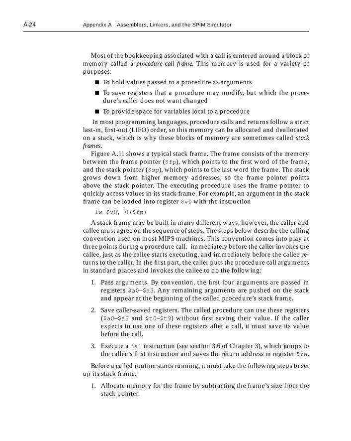
A-24 Appendix A Assemblers, Linkers, and the SPIM Simulator
Most of the bookkeeping associated with a call is centered around a block ofmemory called a procedure call frame. This memory is used for a variety ofpurposes:
■ To hold values passed to a procedure as arguments
■ To save registers that a procedure may modify, but which the proce-dure’s caller does not want changed
■ To provide space for variables local to a procedure
In most programming languages, procedure calls and returns follow a strictlast-in, first-out (LIFO) order, so this memory can be allocated and deallocatedon a stack, which is why these blocks of memory are sometimes called stackframes.
Figure A.11 shows a typical stack frame. The frame consists of the memorybetween the frame pointer ($fp), which points to the first word of the frame,and the stack pointer ($sp), which points to the last word the frame. The stackgrows down from higher memory addresses, so the frame pointer pointsabove the stack pointer. The executing procedure uses the frame pointer toquickly access values in its stack frame. For example, an argument in the stackframe can be loaded into register $v0 with the instruction
lw $v0, 0($fp)
A stack frame may be built in many different ways; however, the caller andcallee must agree on the sequence of steps. The steps below describe the callingconvention used on most MIPS machines. This convention comes into play atthree points during a procedure call: immediately before the caller invokes thecallee, just as the callee starts executing, and immediately before the callee re-turns to the caller. In the first part, the caller puts the procedure call argumentsin standard places and invokes the callee to do the following:
1. Pass arguments. By convention, the first four arguments are passed inregisters $a0–$a3. Any remaining arguments are pushed on the stackand appear at the beginning of the called procedure’s stack frame.
2. Save caller-saved registers. The called procedure can use these registers($a0–$a3 and $t0–$t9) without first saving their value. If the callerexpects to use one of these registers after a call, it must save its valuebefore the call.
3. Execute a jal instruction (see section 3.6 of Chapter 3), which jumps tothe callee’s first instruction and saves the return address in register $ra.
Before a called routine starts running, it must take the following steps to setup its stack frame:
1. Allocate memory for the frame by subtracting the frame’s size from thestack pointer.

A.6 Procedure Call Convention A-25
2. Save callee-saved registers in the frame. A callee must save the valuesin these registers ($s0–$s7, $fp, and $ra) before altering them since thecaller expects to find these registers unchanged after the call. Register$fp is saved by every procedure that allocates a new stack frame. How-ever, register $ra only needs to be saved if the callee itself makes a call.The other callee-saved registers that are used also must be saved.
3. Establish the frame pointer by adding the stack frame’s size minus fourto $sp and storing the sum in register $fp.
FIGURE A.11 Layout of a stack frame. The frame pointer ($fp) points to the first word in thecurrently executing procedure’s stack frame. The stack pointer ($sp) points to the last word offrame. The first four arguments are passed in registers, so the fifth argument is the first onestored on the stack.
The MIPS register use convention provides callee- andcaller-saved registers because both types of registers areadvantageous in different circumstances. Callee-saved reg-isters are better used to hold long-lived values, such as vari-ables from a user’s program. These registers are only savedduring a procedure call if the callee expects to use the regis-ter. On the other hand, caller-saved registers are better used
to hold short-lived quantities that do not persist across a call, such as immedi-ate values in an address calculation. During a call, the callee can also use theseregisters for short-lived temporaries.
Argument 6
Argument 5
Saved registers
Local variables
Higher memory addresses
Lower memory addresses
Stackgrows
$fp
$sp
HardwareSoftwareInterface
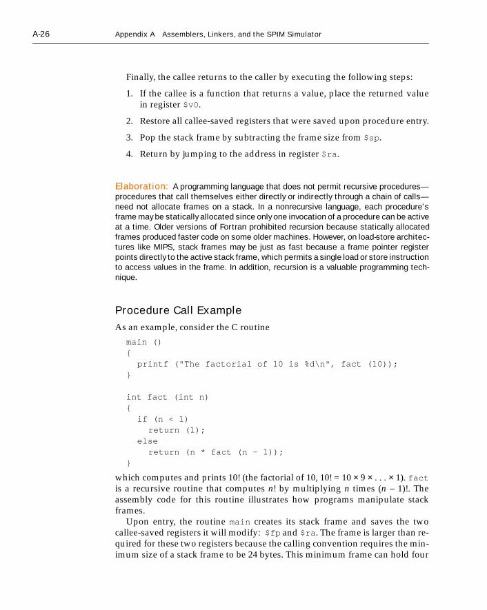
A-26 Appendix A Assemblers, Linkers, and the SPIM Simulator
Finally, the callee returns to the caller by executing the following steps:
1. If the callee is a function that returns a value, place the returned valuein register $v0.
2. Restore all callee-saved registers that were saved upon procedure entry.
3. Pop the stack frame by subtracting the frame size from $sp.
4. Return by jumping to the address in register $ra.
Elaboration: A programming language that does not permit recursive procedures—procedures that call themselves either directly or indirectly through a chain of calls—need not allocate frames on a stack. In a nonrecursive language, each procedure’sframe may be statically allocated since only one invocation of a procedure can be activeat a time. Older versions of Fortran prohibited recursion because statically allocatedframes produced faster code on some older machines. However, on load-store architec-tures like MIPS, stack frames may be just as fast because a frame pointer registerpoints directly to the active stack frame, which permits a single load or store instructionto access values in the frame. In addition, recursion is a valuable programming tech-nique.
Procedure Call ExampleAs an example, consider the C routine
main (){
printf ("The factorial of 10 is %d\n", fact (10));}
int fact (int n){
if (n < 1)return (1);
elsereturn (n * fact (n - 1));
}
which computes and prints 10! (the factorial of 10, 10! = 10 × 9 × . . . × 1). factis a recursive routine that computes n! by multiplying n times (n – 1)!. Theassembly code for this routine illustrates how programs manipulate stackframes.
Upon entry, the routine main creates its stack frame and saves the twocallee-saved registers it will modify: $fp and $ra. The frame is larger than re-quired for these two registers because the calling convention requires the min-imum size of a stack frame to be 24 bytes. This minimum frame can hold four

A.6 Procedure Call Convention A-27
argument registers ($a0–$a3) and the return address $ra, padded to a double-word boundary (24 bytes). Since main also needs to save $fp, its stack framemust be two words larger (remember: the stack pointer is kept doublewordaligned).
.text
.globl mainmain:
subu $sp,$sp,32 # Stack frame is 32 bytes longsw $ra,20($sp) # Save return addresssw $fp,16($sp) # Save old frame pointeraddu $fp,$sp,28 # Set up frame pointer
The routine main then calls the factorial routine and passes it the single argu-ment 10. After fact returns, main calls the library routine printf and passesit both a format string and the result returned from fact:
li $a0,10 # Put argument (10) in $a0jal fact # Call factorial function
la $a0,$LC # Put format string in $a0move $a1,$v0 # Move fact result to $a1jal printf # Call the print function
Finally, after printing the factorial, main returns. But first, it must restore theregisters it saved and pop its stack frame:
lw $ra,20($sp) # Restore return addresslw $fp,16($sp) # Restore frame pointeraddu $sp,$sp,32 # Pop stack framejr $ra # Return to caller
.rdata$LC:
.ascii “The factorial of 10 is %d\n\000”
The factorial routine is similar in structure to main. First, it creates a stackframe and saves the callee-saved registers it will use. In addition to saving$ra and $fp, fact also saves its argument ($a0), which it will use for therecursive call:
.textfact:
subu $sp,$sp,32 # Stack frame is 32 bytes longsw $ra,20($sp) # Save return addresssw $fp,16($sp) # Save frame pointeraddu $fp,$sp,28 # Set up frame pointersw $a0,0($fp) # Save argument (n)

A-28 Appendix A Assemblers, Linkers, and the SPIM Simulator
The heart of the fact routine performs the computation from the C pro-gram. It tests if the argument is greater than 0. If not, the routine returns thevalue 1. If the argument is greater than 0, the routine recursively calls itself tocompute fact(n-1) and multiplies that value times n:
lw $v0,0($fp) # Load nbgtz $v0,$L2 # Branch if n > 0li $v0,1 # Return 1j $L1 # Jump to code to return
$L2:lw $v1,0($fp) # Load nsubu $v0,$v1,1 # Compute n - 1move $a0,$v0 # Move value to $a0jal fact # Call factorial function
lw $v1,0($fp) # Load nmul $v0,$v0,$v1 # Compute fact(n-1) * n
Finally, the factorial routine restores the callee-saved registers and returnsthe value in register $v0:
$L1: # Result is in $v0lw $ra, 20($sp) # Restore $ralw $fp, 16($sp) # Restore $fpaddu $sp, $sp, 32 # Pop stackj $ra # Return to caller
Stack in Recursive Procedure
Figure A.12 shows the stack at the call fact(7). main runs first, so itsframe is deepest on the stack. main calls fact(10), whose stack frame isnext on the stack. Each invocation recursively invokes fact to computethe next-lowest factorial. The stack frames parallel the LIFO order of thesecalls. What does the stack look like when the call to fact(10) returns?
Example

A.6 Procedure Call Convention A-29
Elaboration: The difference between the MIPS compiler and the gcc compiler is thatthe MIPS compiler usually does not use a frame pointer, so this register is available asanother callee-saved register, $s8. This change saves a couple of instructions in theprocedure call and return sequence. However, it complicates code generation becausea procedure must access its stack frame with $sp, whose value can change during aprocedure’s execution if values are pushed on the stack.
Another Procedure Call ExampleAs another example, consider the following routine that computes the takfunction, which is a widely used benchmark created by Ikuo Takeuchi. Thisfunction does not compute anything useful, but is a heavily recursive pro-gram that illustrates the MIPS calling convention.
FIGURE A.12 Stack frames during the call of fact(7).
main
fact (10)
fact (9)
fact (8)
fact (7)
Stack
Stack grows
Old $raOld $fpOld $a0
Old $raOld $fpOld $a0
Old $raOld $fpOld $a0
Old $raOld $fpOld $a0
Old $raOld $fp
main
Stack
Stack growsOld $raOld $fp
Answer

A-30 Appendix A Assemblers, Linkers, and the SPIM Simulator
int tak (int x, int y, int z){
if (y < x)return 1+ tak (tak (x - 1, y, z),
tak (y - 1, z, x),tak (z - 1, x, y));
elsereturn z;
}
int main (){
tak(18, 12, 6);}
The assembly code for this program is below. The tak function first saves itsreturn address in its stack frame and its arguments in callee-saved registers,since the routine may make calls that need to use registers $a0–$a2 and $ra.The function uses callee-saved registers since they hold values that persistover the lifetime of the function, which includes several calls that couldpotentially modify registers.
.text
.globl tak
tak:subu $sp, $sp, 40sw $ra, 32($sp)
sw $s0, 16($sp) # xmove $s0, $a0sw $s1, 20($sp) # ymove $s1, $a1sw $s2, 24($sp) # zmove $s2, $a2sw $s3, 28($sp) # temporary
The routine then begins execution by testing if y < x. If not, it branches to labelL1, which is below.
bge $s1, $s0, L1 # if (y < x)
If y < x, then it executes the body of the routine, which contains four recursivecalls. The first call uses almost the same arguments as its parent:
addu $a0, $s0, -1move $a1, $s1move $a2, $s2jal tak # tak (x - 1, y, z)move $s3, $v0

A.6 Procedure Call Convention A-31
Note that the result from the first recursive call is saved in register $s3, so thatit can be used latter.
The function now prepares arguments for the second recursive call.
addu $a0, $s1, -1move $a1, $s2move $a2, $s0jal tak # tak (y - 1, z, x)
In the instructions below, the result from this recursive call is saved in register$s0. But, first we need to read, for the last time, the saved value of the firstargument from this register.
addu $a0, $s2, -1move $a1, $s0move $a2, $s1move $s0, $v0jal tak # tak (z - 1, x, y)
After the three inner recursive calls, we are ready for the final recursive call.After the call, the function’s result is in $v0 and control jumps to the func-tion’s epilogue.
move $a0, $s3move $a1, $s0move $a2, $v0jal tak # tak (tak(...), tak(...), tak(...))j L2
This code at label L1 is the consequent of the if-then-else statement. It justmoves the value of argument z into the return register and falls into the func-tion epilogue.
L1:move $v0, $s2
The code below is the function epilogue, which restores the saved registersand returns the function’s result to its caller.
L2:lw $ra, 32($sp)lw $s0, 16($sp)lw $s1, 20($sp)lw $s2, 24($sp)lw $s3, 28($sp)addu $sp, $sp, 40j $ra

A-32 Appendix A Assemblers, Linkers, and the SPIM Simulator
The main routine calls the tak function with its initial arguments, then takesthe computed result (7) and prints it using SPIM’s system call for printingintegers.
.globl mainmain:
subu $sp, $sp, 24sw $ra, 16($sp)
li $a0, 18li $a1, 12li $a2, 6jal tak # tak(18, 12, 6)
move $a0, $v0li $v0, 1 # print_int syscallsyscall
lw $ra, 16($sp)addu $sp, $sp, 24j $ra
Section 5.6 of Chapter 5 describes the MIPS exception facility, which respondsboth to exceptions caused by errors during an instruction’s execution and toexternal interrupts caused by I/O devices. This section describes exceptionand interrupt handling in more detail. In MIPS processors, a part of the CPUcalled coprocessor 0 records the information the software needs to handleexceptions and interrupts. The MIPS simulator SPIM does not implement allof coprocessor 0’s registers, since many are not useful in a simulator or arepart of the memory system, which SPIM does not implement. However, SPIMdoes provide the following coprocessor 0 registers:
These four registers are part of coprocessor 0’s register set and are accessed bythe lwc0, mfc0, mtc0, and swc0 instructions. After an exception, register EPC
A.7 Exceptions and Interrupts A.7
Registername
Registernumber Usage
BadVAddr 08 register containing the memory address at which memory reference occurred
Status 12 interrupt mask and enable bits
Cause 13 exception type and pending interrupt bits
EPC 14 register containing address of instruction that caused exception
A.7 Exceptions and Interrupts A-33
contains the address of the instruction that was executing when the exceptionoccurred. If the instruction made a memory access that caused the exception,register BadVAddr contains the referenced memory location’s address. Thetwo other registers contain many fields and are described below.
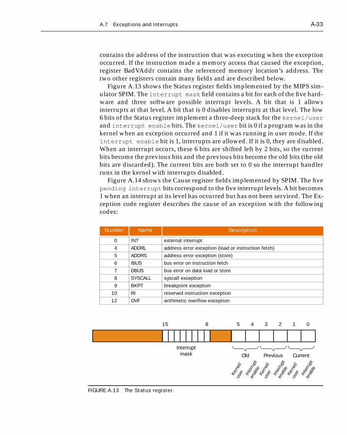
Figure A.13 shows the Status register fields implemented by the MIPS sim-ulator SPIM. The interrupt mask field contains a bit for each of the five hard-ware and three software possible interrupt levels. A bit that is 1 allowsinterrupts at that level. A bit that is 0 disables interrupts at that level. The low6 bits of the Status register implement a three-deep stack for the kernel/userand interrupt enable bits. The kernel/user bit is 0 if a program was in thekernel when an exception occurred and 1 if it was running in user mode. If theinterrupt enable bit is 1, interrupts are allowed. If it is 0, they are disabled.When an interrupt occurs, these 6 bits are shifted left by 2 bits, so the currentbits become the previous bits and the previous bits become the old bits (the oldbits are discarded). The current bits are both set to 0 so the interrupt handlerruns in the kernel with interrupts disabled.
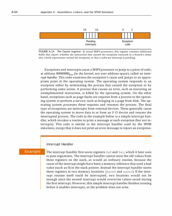
Figure A.14 shows the Cause register fields implemented by SPIM. The fivepending interrupt bits correspond to the five interrupt levels. A bit becomes1 when an interrupt at its level has occurred but has not been serviced. The Ex-ception code register describes the cause of an exception with the followingcodes:
Number Name Description
00 INT external interrupt
04 ADDRL address error exception (load or instruction fetch)
05 ADDRS address error exception (store)
06 IBUS bus error on instruction fetch
07 DBUS bus error on data load or store
08 SYSCALL syscall exception
09 BKPT breakpoint exception
10 RI reserved instruction exception
12 OVF arithmetic overflow exception
FIGURE A.13 The Status register.
15 8 5 4 3 2 1 0
Interruptmask Old Previous Current
Kern
el/
user Inte
rrupt
enab
leKe
rnel
/us
er Kern
el/
userInte
rrupt
enab
le
Inte
rrupt
enab
le
A-34 Appendix A Assemblers, Linkers, and the SPIM Simulator
Exceptions and interrupts cause a MIPS processor to jump to a piece of code,at address 80000080hex (in the kernel, not user address space), called an inter-rupt handler. This code examines the exception’s cause and jumps to an appro-priate point in the operating system. The operating system responds to anexception either by terminating the process that caused the exception or byperforming some action. A process that causes an error, such as executing anunimplemented instruction, is killed by the operating system. On the otherhand, exceptions such as page faults are requests from a process to the operat-ing system to perform a service, such as bringing in a page from disk. The op-erating system processes these requests and resumes the process. The finaltype of exceptions are interrupts from external devices. These generally causethe operating system to move data to or from an I/O device and resume theinterrupted process. The code in the example below is a simple interrupt han-dler, which invokes a routine to print a message at each exception (but not in-terrupts). This code is similar to the interrupt handler used by the SPIMsimulator, except that it does not print an error message to report an exception.
FIGURE A.14 The Cause register. In actual MIPS processors, this register contains additionalfields that report: whether the instruction that caused the exception executed in a branch’s delayslot, which coprocessor caused the exception, or that a software interrupt is pending.
Interrupt Handler
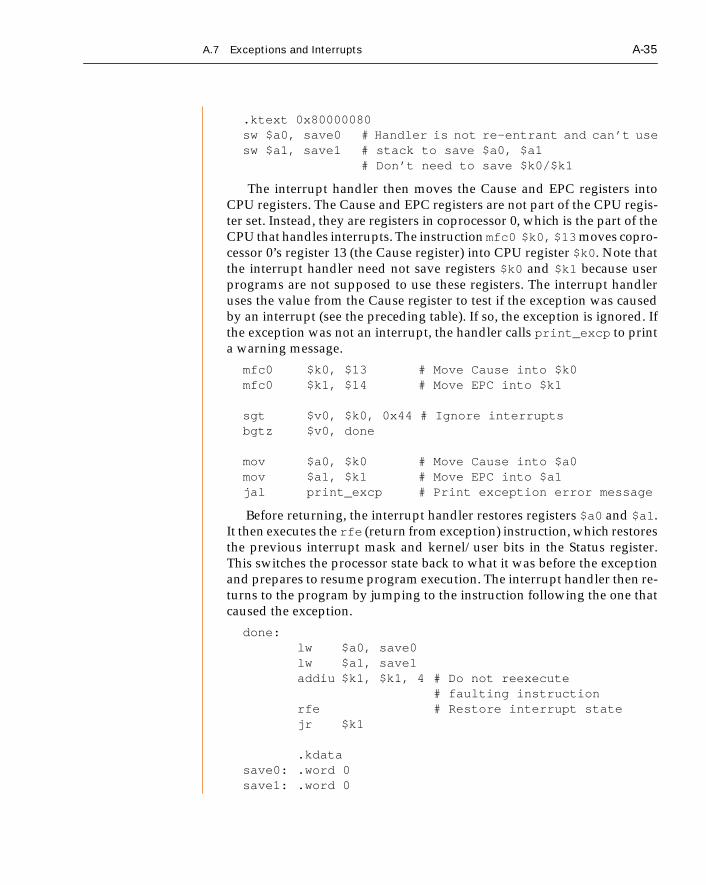
The interrupt handler first saves registers $a0 and $a1, which it later usesto pass arguments. The interrupt handler cannot store the old values fromthese registers on the stack, as would an ordinary routine, because thecause of the interrupt might have been a memory reference that used a badvalue (such as 0) in the stack pointer. Instead the interrupt handler storesthese registers in two memory locations (save0 and save1). If the inter-rupt routine itself could be interrupted, two locations would not beenough since the second interrupt would overwrite values saved duringthe first interrupt. However, this simple interrupt handler finishes runningbefore it enables interrupts, so the problem does not arise.
15 10 5 2
Pendinginterrupts
Exceptioncode
Example
A.7 Exceptions and Interrupts A-35
.ktext 0x80000080sw $a0, save0 # Handler is not re-entrant and can’t usesw $a1, save1 # stack to save $a0, $a1
# Don’t need to save $k0/$k1
The interrupt handler then moves the Cause and EPC registers intoCPU registers. The Cause and EPC registers are not part of the CPU regis-ter set. Instead, they are registers in coprocessor 0, which is the part of theCPU that handles interrupts. The instruction mfc0 $k0, $13 moves copro-cessor 0’s register 13 (the Cause register) into CPU register $k0. Note thatthe interrupt handler need not save registers $k0 and $k1 because userprograms are not supposed to use these registers. The interrupt handleruses the value from the Cause register to test if the exception was causedby an interrupt (see the preceding table). If so, the exception is ignored. Ifthe exception was not an interrupt, the handler calls print_excp to printa warning message.
mfc0 $k0, $13 # Move Cause into $k0mfc0 $k1, $14 # Move EPC into $k1
sgt $v0, $k0, 0x44 # Ignore interruptsbgtz $v0, done
mov $a0, $k0 # Move Cause into $a0mov $a1, $k1 # Move EPC into $a1jal print_excp # Print exception error message
Before returning, the interrupt handler restores registers $a0 and $a1.It then executes the rfe (return from exception) instruction, which restoresthe previous interrupt mask and kernel/user bits in the Status register.This switches the processor state back to what it was before the exceptionand prepares to resume program execution. The interrupt handler then re-turns to the program by jumping to the instruction following the one thatcaused the exception.
done:lw $a0, save0
lw $a1, save1 addiu $k1, $k1, 4 # Do not reexecute
# faulting instruction rfe # Restore interrupt state jr $k1
.kdatasave0: .word 0save1: .word 0

A-36 Appendix A Assemblers, Linkers, and the SPIM Simulator
Elaboration: On real MIPS processors, the return from an interrupt handler is morecomplex. The rfe instruction must execute in the delay slot of the jr instruction (seeelaboration on page 444 of Chapter 6) that returns to the user program so that no inter-rupt-handler instruction executes with the user program’s interrupt mask and ker-nel/user bits. In addition, the interrupt handler cannot always jump to the instructionfollowing EPC. For example, if the instruction that caused the exception was in a branchinstruction’s delay slot (see Chapter 6), the next instruction may not be the followinginstruction in memory.
SPIM simulates one I/O device: a memory-mapped terminal. When a pro-gram is running, SPIM connects its own terminal (or a separate console win-dow in the X-window version xspim) to the processor. A MIPS programrunning on SPIM can read the characters that you type. In addition, if theMIPS program writes characters to the terminal, they appear on SPIM’s termi-nal or console window. One exception to this rule is control-C: this characteris not passed to the program, but instead causes SPIM to stop and return tocommand mode. When the program stops running (for example, because youtyped control-C or because the program hit a breakpoint), the termi-nal is reconnected to spim so you can type SPIM commands. To usememory-mapped I/O (see below), spim or xspim must be started with the-mapped_io flag.
The terminal device consists of two independent units: a receiver and atransmitter. The receiver reads characters from the keyboard. The transmitterwrites characters to the display. The two units are completely independent.This means, for example, that characters typed at the keyboard are not auto-matically echoed on the display. Instead, a program must explicitly echo acharacter by reading it from the receiver and writing it to the transmitter.
A program controls the terminal with four memory-mapped device regis-ters, as shown in Figure A.15. “Memory-mapped’’ means that each registerappears as a special memory location. The Receiver Control register is at locationffff0000hex. Only two of its bits are actually used. Bit 0 is called “ready’’: if it is1, it means that a character has arrived from the keyboard but has not yet beenread from the Receiver Data register. The ready bit is read-only: writes to it areignored. The ready bit changes from 0 to 1 when a character is typed at the key-board, and it changes from 1 to 0 when the character is read from the ReceiverData register.
Bit 1 of the Receiver Control register is the keyboard “interrupt enable.” Thisbit may be both read and written by a program. The interrupt enable is initially0. If it is set to 1 by a program, the terminal requests an interrupt at level 0whenever the ready bit is 1. However, for the interrupt to affect the processor,
A.8 Input and Output A.8

A.8 Input and Output A-37
interrupts must also be enabled in the Status register (see section A.7). All oth-er bits of the Receiver Control register are unused.
The second terminal device register is the Receiver Data register (at addressffff0004hex). The low-order 8 bits of this register contain the last character typedat the keyboard. All other bits contain 0s. This register is read-only and changesonly when a new character is typed at the keyboard. Reading the Receiver Dataregister resets the ready bit in the Receiver Control register to 0.
The third terminal device register is the Transmitter Control register (at ad-dress ffff0008hex). Only the low-order 2 bits of this register are used. They be-have much like the corresponding bits of the Receiver Control register. Bit 0 iscalled “ready’’ and is read-only. If this bit is 1, the transmitter is ready to accepta new character for output. If it is 0, the transmitter is still busy writing the pre-vious character. Bit 1 is “interrupt enable’’ and is readable and writable. If thisbit is set to 1, then the terminal requests an interrupt on level 1 whenever theready bit is 1.
The final device register is the Transmitter Data register (at addressffff000chex). When a value is written into this location, its low-order 8 bits (i.e.,
FIGURE A.15 The terminal is controlled by four device registers, each of which appearsas a memory location at the given address. Only a few bits of these registers are actuallyused. The others always read as 0s and are ignored on writes.
1
Interruptenable
Ready
1Unused
Receiver control(0xffff0000)
8
Received byte
Unused
Receiver data(0xffff0004)
1
Interruptenable
Ready
1Unused
Transmitter control(0xffff0008)
Transmitter data(0xffff000c)
8
Transmitted byte
Unused

A-38 Appendix A Assemblers, Linkers, and the SPIM Simulator
an ASCII character as in Figure 3.15 in Chapter 3) are sent to the console. Whenthe Transmitter Data register is written, the ready bit in the Transmitter Controlregister is reset to 0. This bit stays 0 until enough time has elapsed to transmitthe character to the terminal; then the ready bit becomes 1 again. The Trans-mitter Data register should only be written when the ready bit of the Transmit-ter Control register is 1. If the transmitter is not ready, writes to the TransmitterData register are ignored (the write appears to succeed but the character is notoutput).
Real computers require time to send characters over the serial lines that con-nect terminals to computers. These time lags are simulated by SPIM. For exam-ple, after the transmitter starts to write a character, the transmitter’s ready bitbecomes 0 for a while. SPIM measures time in instructions executed, not in realclock time. This means that the transmitter does not become ready again untilthe processor executes a certain number of instructions. If you stop the ma-chine and look at the ready bit, it will not change. However, if you let the ma-chine run, the bit eventually changes back to 1.
SPIM is a software simulator that runs programs written for MIPSR2000/R3000 processors. SPIM’s name is just MIPS spelled backwards. SPIMcan read and immediately execute assembly language files or (on some sys-tems) MIPS executable files. SPIM is a self-contained system for running MIPSprograms. It contains a debugger and provides a few operating system-likeservices. SPIM is much slower than a real computer (100 or more times).However, its low cost and wide availability cannot be matched by real hard-ware!
An obvious question is, Why use a simulator when many people haveworkstations that contain MIPS chips that are significantly faster than SPIM?One reason is that these workstations are not universally available. Anotherreason is rapid progress toward new and faster computers may render thesemachines obsolete (see Chapter 1). The current trend is to make computersfaster by executing several instructions concurrently. This trend makes archi-tectures more difficult to understand and program. The MIPS architecture maybe the epitome of a simple, clean RISC machine.
In addition, simulators can provide a better environment for programmingthan an actual machine because they can detect more errors and provide morefeatures than an actual computer. For example, SPIM has an X-window inter-face that works better than most debuggers on the actual machines.
Finally, simulators are a useful tool in studying computers and the pro-grams that run on them. Because they are implemented in software, not silicon,simulators can be easily modified to add new instructions, build new systemssuch as multiprocessors, or simply to collect data.
A.9 SPIM A.9

A.9 SPIM A-39
Simulation of a Virtual MachineThe MIPS architecture, like that of many RISC computers, is difficult to pro-gram directly because of delayed branches, delayed loads, and restrictedaddress modes. This difficulty is tolerable since these computers weredesigned to be programmed in high-level languages and present an interfaceappropriate for compilers rather than assembly language programmers. Agood part of the programming complexity results from delayed instructions.A delayed branch requires two cycles to execute (see elaborations on pages 444and 502 of Chapter 6). In the second cycle, the instruction immediately fol-lowing the branch executes. This instruction can perform useful work thatnormally would have been done before the branch. It can also be a nop (nooperation). Similarly, delayed loads require two cycles so the instruction imme-diately following a load cannot use the value loaded from memory (seesection 6.2 of Chapter 6).
MIPS wisely chose to hide this complexity by having its assembler imple-ment a virtual machine. This virtual computer appears to have nondelayedbranches and loads and a richer instruction set than the actual hardware. Theassembler reorganizes (rearranges) instructions to fill the delay slots. The virtualcomputer also provides pseudoinstructions, which appear as real instructions inassembly language programs. The hardware, however, knows nothing aboutpseudoinstructions, so the assembler must translate them into equivalent se-quences of actual, machine instructions. For example, the MIPS hardware onlyprovides instructions to branch when a register is equal to or not equal to 0.Other conditional branches, such as when one register is greater than another,are synthesized by comparing the two registers and branching when the resultof the comparison is true (nonzero).
By default, SPIM simulates the richer virtual machine. However, it can alsosimulate the bare hardware. Below, we describe the virtual machine and onlymention in passing features that do not belong to the actual hardware. In doingso, we follow the convention of MIPS assembly language programmers (andcompilers), who routinely use the extended machine. (For a description of thereal machines, see Gerry Kane and Joe Heinrich, MIPS RISC Architecture, Pren-tice Hall, Englewood Cliff, NJ, 1992.)
Getting Started with SPIMThe rest of this appendix contains a complete and rather detailed descriptionof SPIM. Many details should never concern you; however, the sheer volumeof information can obscure the fact that SPIM is a simple, easy-to-use pro-gram. This section contains a quick tutorial on SPIM that should enable you toload, debug, and run simple MIPS programs.
A-40 Appendix A Assemblers, Linkers, and the SPIM Simulator
SPIM comes in multiple versions. One version, called spim, is a command-line-driven program and requires only an alphanumeric terminal to display it.It operates like most programs of this type: you type a line of text, hit the re-turn key, and spim executes your command.
A fancier version, called xspim, runs in the X-windows environment of theUnix system and therefore requires a bit-mapped display to run it. xspim,however, is a much easier program to learn and use because its commands arealways visible on the screen and because it continually displays the machine’sregisters. Another version, PCspim, is compatible with Windows 3.1, Windows95, and Windows NT. The Unix, Windows, and DOS versions of SPIM areavailable through www.mkp.com/cod2e.htm.
Since many people use and prefer xspim, this section only discusses thatprogram. If you plan to use any version of spim, do not skip this section. Readit first and then look at the "SPIM Command-Line Options" section (starting onpage A-44) to see how to accomplish the same thing with spim commands.Check www.mkp.com/cod2e.htm for more information on using PCspim.
To start xspim, type xspim in response to your system’s prompt (%):
% xspim
On your system, xspim may be kept in an unusual place, and you may needto execute a command first to add that place to your search path. Your instruc-tor should tell you how to do this.
When xspim starts up, it pops up a large window on your screen (seeFigure A.16). The window is divided into five panes:
■ The top pane is called the register display. It shows the values of all reg-isters in the MIPS CPU and FPU. This display is updated wheneveryour program stops running.
■ The pane below contains the control buttons to operate xspim. These but-tons are discussed below, so we can skip the details for now.
■ The next pane, called the text segments, displays instructions both fromyour program and the system code that is loaded automatically whenxspim starts running. Each instruction is displayed on a line that looks like
[0x00400000] 0x8fa40000 lw $4, 0($29) ; 89: lw $a0, 0($sp)
The first number on the line, in square brackets, is the hexadecimalmemory address of the instruction. The second number is the instruc-tion’s numerical encoding, again displayed as a hexadecimal number.The third item is the instruction’s mnemonic description. Everythingfollowing the semicolon is the actual line from your assembly file thatproduced the instruction. The number 89 is the line number in that file.Sometimes nothing is on the line after the semicolon. This means thatthe instruction was produced by SPIM as part of translating a pseudo-instruction.

A.9 SPIM A-41
FIGURE A.16 SPIM’s X-window interface: xspim.
xspim
quit
PCStatus
R0R1R2R3R4R5R6R7
FP0FP2FP4FP6
(r0)(at)(v0)(v1)(a0)(a1)(a2)(a3)
========
====
0000000000000000000000000000000000000000000000000000000000000000
0.0000000.0000000.0000000.000000
==
0000000000000000
EPCHI
==
0000000000000000
CauseLO
==
0000000000000000
BadVaddr = 00000000
R8R9R10R11R12R13R14R15
FP8FP10FP12FP14
(t0)(t1)(t2)(t3)(t4)(t5)(t6)(t7)
========
====
0000000000000000000000000000000000000000000000000000000000000000
0.0000000.0000000.0000000.000000
R16R17R18R19R20R21R22R23
FP16FP18FP20FP22
(s0)(s1)(s2)(s3)(s4)(s5)(s6)(s7)
========
====
0000000000000000000000000000000000000000000000000000000000000000
0.0000000.0000000.0000000.000000
R24R25R26R27R28R29R30R31
FP24FP26FP28FP30
(t8)(s9)(k0)(k1)(gp)(sp)(s8)(ra)
========
====
0000000000000000000000000000000000000000000000000000000000000000
0.0000000.0000000.0000000.000000
load
breakpt
run
help
step
terminal
clear
mode
set value
Text segments
Data segments
[0x00400000][0x00400004][0x00400008][0x0040000c][0x00400010][0x00400014][0x00400018][0x0040001c]
0x8fa400000x27a500040x24a600040x000410800x00c230210x0c0000000x3402000a0x0000000c
lw $4, 0($29)addiu $5, $29, 4addiu $6, $5, 4sll $2, $4, 2addu $6, $6, $2jal 0x00000000 [main]ori $2, $0, 10syscall
lw $a0, 0($sp)addiu $al, $sp, 4addiu $a2, $al, 4sll $v0, $a0, 2addu $a2, $a2, $v0jal mainli $v0 10syscall
;;;;;;;;
89:90:91:92:93:94:95:96:
[0x10000000] ... [0x10010000] 0x00000000[0x10010004][0x10010010][0x10010020][0x10010030][0x10010040][0x10010050][0x10010060][0x10010070]
0x747065630x727275630x000a64650x0000205d0x612064650x642f74730x555b20200x73736572
0x206e6f690x612064650x495b20200x202000000x657264640x206174610x696c616e0x206e6920
0x636f20000x6920646e0x7265746e0x616e555b0x692073730x637465660x64656e670x726f7473
0x726f6e670x747075720x6e67696c0x6e69206e0x00205d680x646461200x00205d65
SPIM Version 5.9 of January 17, 1997Copyright (c) 1990–1997 by James R. Larus ([email protected])All Rights Reserved.See the file README for a full copyright notice.
General registers
Double floating-point registers
Single floating-point registers
Register display
Controlbuttons
Textsegments
Data andstacksegments
SPIMmessages

A-42 Appendix A Assemblers, Linkers, and the SPIM Simulator
■ The next pane, called the data and stack segments, displays the data load-ed into your program’s memory and the data on the program’s stack.
■ The bottom pane is the SPIM messages that xspim uses to write mes-sages. This is where error messages appear.
Let’s see how to load and run a program. The first thing to do is to click onthe load button (the second one in the first row of buttons) with the left mousekey. Your click tells xspim to pop up a small prompt window that contains abox and two or three buttons. Move your mouse so the cursor is over the box,and type the name of your file of assembly code. Then click on the buttonlabeled assembly file within that prompt window. If you change your mind,click on the button labeled abort command, and xspim gets rid of the promptwindow. When you click on assembly file, xspim gets rid of the prompt win-dow, then loads your program and redraws the screen to display its instruc-tions and data. Now move the mouse to put the cursor over the scrollbar to theleft of the text segments, and click the left mouse button on the white part ofthis scrollbar. A click scrolls the text pane down so you can find all the instruc-tions in your program.
To run your program, click on the run button in xspim’s control buttonpane. It pops up a prompt window with two boxes and two buttons. Most ofthe time, these boxes contain the correct values to run your program, so youcan ignore them and just click on ok. This button tells xspim to run your pro-gram. Notice that when your program is running, xspim blanks out the regis-ter display pane because the registers are continually changing. You canalways tell whether xspim is running by looking at this pane. If you want tostop your program, make sure the mouse cursor is somewhere over xspim’swindow and type control-C. This causes xspim to pop up a prompt windowwith two buttons. Before doing anything with this prompt window, you canlook at registers and memory to find out what your program was doing. Whenyou understand what happened, you can either continue the program by click-ing on continue or stop your program by clicking on abort command.
If your program reads or writes from the terminal, xspim pops up anotherwindow called the console. All characters that your program writes appear onthe console, and everything that you type as input to your program should betyped in this window.
Suppose your program does not do what you expect. What can you do?SPIM has two features that help debug your program. The first, and perhapsthe most useful, is single-stepping, which allows you to run your program aninstruction at a time. Click on the button labeled step and another promptwindow pops up. This prompt window contains two boxes and three buttons.The first box asks for the number of instructions to step every time you clickthe mouse. Most of the time, the default value of 1 is a good choice. The otherbox asks for arguments to pass to the program when it starts running. Again,

A.9 SPIM A-43
most of the time you can ignore this box because it contains an appropriatevalue. The button labeled step runs your program for the number of instruc-tions in the top box. If that number is 1, xspim executes the next instruction inyour program, updates the display, and returns control to you. The button la-beled continue stops single-stepping and continues running your program.Finally, abort command stops single-stepping and leaves your programstopped.
What do you do if your program runs for a long time before the bug arises?You could single-step until you get to the bug, but that can take a long time,and it is easy to get so bored and inattentive that you step past the problem. Abetter alternative is to use a breakpoint, which tells xspim to stop your programimmediately before it executes a particular instruction. Click on the button inthe second row of buttons marked breakpoints. The xspim program pops upa prompt window with one box and many buttons. Type in this box the ad-dress of the instruction at which you want to stop. Or, if the instruction has aglobal label, you can just type the name of the label. Labeled breakpoints are aparticularly convenient way to stop at the first instruction of a procedure. Toactually set the breakpoint, click on add. You can then run your program.
When SPIM is about to execute the breakpointed instruction, xspim pops upa prompt with the instruction’s address and two buttons. The continue but-ton continues running your program and abort command stops your program.If you want to delete a breakpoint, type in its address and click on delete.Finally, list tells xspim to print (in the bottom pane) a list of all breakpointsthat are set.
Single-stepping and setting breakpoints will probably help you find a bugin your program quickly. How do you fix it? Go back to the editor that youused to create your program and change it. To run the program again, youneed a fresh copy of SPIM, which you get in two ways. Either you can exit fromxspim by clicking on the quit button, or you can clear xspim and reload yourprogram. If you reload your program, you must clear the memory, so remnantsof your previous program do not interfere with your new program. To do this,click on the button labeled clear. Hold the left mouse key down and a two-item menu will pop up. Move the mouse so the cursor is over the item labeledmemory & registers and release the key. This causes xspim to clear its mem-ory and registers and return the processor to the state it was in when xspimfirst started. You can now load and run your new program.
The other buttons in xspim perform functions that are occasionally useful.When you are more comfortable with xspim, you should look at the descrip-tion below to see what they do and how they can save you time and effort.

A-44 Appendix A Assemblers, Linkers, and the SPIM Simulator
SPIM Command-Line OptionsBoth Unix versions of SPIM—spim, the terminal version, and xspim, the Xversion—accept the following command-line options:
-bare Simulate a bare MIPS machine without pseudoinstructionsor the additional addressing modes provided by theassembler. Implies -quiet.
-asm Simulate the virtual MIPS machine provided by theassembler. This is the default.
-pseudo Allow the input assembly code to contain pseudoinstruc-tions. This is the default.
-nopseudo Do not allow pseudoinstructions in the input assemblycode.
-notrap Do not load the standard exception handler and start-upcode. This exception handler handles exceptions. When anexception occurs, SPIM jumps to location 80000080hex,which must contain code to service the exception. In addi-tion, this file contains start-up code that invokes the rou-tine main. Without the start-up routine, SPIM beginsexecution at the instruction labeled __start.
-trap Load the standard exception handler and start-up code.This is the default.
-noquiet Print a message when an exception occurs. This is thedefault.
-quiet Do not print a message at exceptions.
-nomapped_io Disable the memory-mapped I/O facility (see section A.8).This is the default.
-mapped_io Enable the memory-mapped I/O facility (see section A.8).Programs that use SPIM syscalls (see section on "SystemCalls," page A-48) to read from the terminal cannot alsouse memory-mapped I/O.
-file Load and execute the assembly code in the file.
-execute Load and execute the code in the MIPS executable filea.out. This command is only available when SPIM runs ona system containing a MIPS processor.
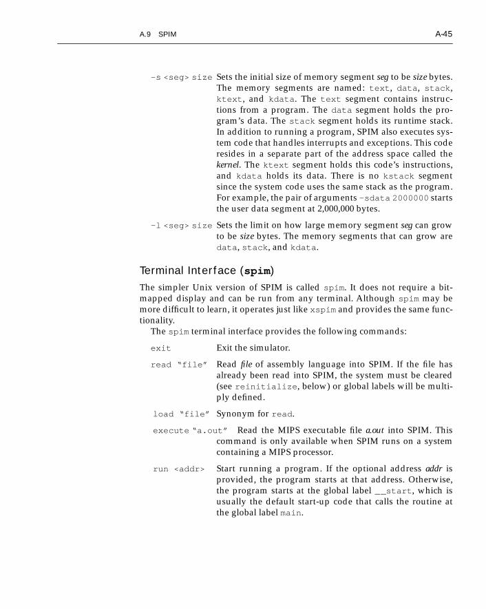
A.9 SPIM A-45
-s <seg> size Sets the initial size of memory segment seg to be size bytes.The memory segments are named: text, data, stack,ktext, and kdata. The text segment contains instruc-tions from a program. The data segment holds the pro-gram’s data. The stack segment holds its runtime stack.In addition to running a program, SPIM also executes sys-tem code that handles interrupts and exceptions. This coderesides in a separate part of the address space called thekernel. The ktext segment holds this code’s instructions,and kdata holds its data. There is no kstack segmentsince the system code uses the same stack as the program.For example, the pair of arguments -sdata 2000000 startsthe user data segment at 2,000,000 bytes.
-l <seg> size Sets the limit on how large memory segment seg can growto be size bytes. The memory segments that can grow aredata, stack, and kdata.
Terminal Interface (spim)The simpler Unix version of SPIM is called spim. It does not require a bit-mapped display and can be run from any terminal. Although spim may bemore difficult to learn, it operates just like xspim and provides the same func-tionality.
The spim terminal interface provides the following commands:
exit Exit the simulator.
read “file” Read file of assembly language into SPIM. If the file hasalready been read into SPIM, the system must be cleared(see reinitialize, below) or global labels will be multi-ply defined.
load “file” Synonym for read.
execute “a.out” Read the MIPS executable file a.out into SPIM. Thiscommand is only available when SPIM runs on a systemcontaining a MIPS processor.
run <addr> Start running a program. If the optional address addr isprovided, the program starts at that address. Otherwise,the program starts at the global label __start, which isusually the default start-up code that calls the routine atthe global label main.

A-46 Appendix A Assemblers, Linkers, and the SPIM Simulator
step <N> Step the program for N (default: 1) instructions. Printinstructions as they execute.
continue Continue program execution without stepping.
print $N Print register N.
print $fN Print floating point register N.
print addr Print the contents of memory at address addr.
print_sym Print the names and addresses of the global labels knownto SPIM. Labels are local by default and become globalonly when declared in a .globl assembler directive (see"Assember Syntax" section on page A-51).
reinitializeClear the memory and registers.
breakpoint addr Set a breakpoint at address addr. addr can be either amemory address or symbolic label.
delete addr Delete all breakpoints at address addr.
list List all breakpoints.
. Rest of line is an assembly instruction that is stored inmemory.
<nl> A newline reexecutes previous command.
? Print a help message.
Most commands can be abbreviated to their unique prefix (e.g., ex, re, l, ru,s, p). More dangerous commands, such as reinitialize, require a longerprefix.
X-Window Interface (xspim)The tutorial, “Getting Started with SPIM” (page A-39), explains the mostcommon xspim commands. However, xspim has other commands that areoccasionally useful. This section provides a complete list of the commands.
The X version of SPIM, xspim, looks different but operates in the same man-ner as spim. The X-window has five panes (see Figure A.16). The top pane dis-plays the registers. These values are continually updated, except while aprogram is running.
The next pane contains buttons that control the simulator:
quit Exit from the simulator.
load Read a source or executable file into SPIM.
A.9 SPIM A-47
run Start the program running.
step Single-step a program.
clear Reinitialize registers or memory.
set value Set the value in a register or memory location.
print Print the value in a register or memory location.
breakpoint Set or delete a breakpoint or list all breakpoints.
help Print a help message.
terminal Raise or hide the console window.
mode Set SPIM operating modes.
The next two panes display the memory. The top one shows instructionsfrom the user and kernel text segments. (These instructions are real—notpseudo—MIPS instructions. SPIM translates assembler pseudoinstructionsinto one to three MIPS instructions. Each source instruction appears as a com-ment on the first instruction into which it is translated.) The first few instruc-tions in the text segment are the default start-up code (__start) that loadsargc and argv into registers and invokes the main routine. The lower of thesetwo panes displays the data and stack segments. Both panes are updated as aprogram executes.
The bottom pane is used to display SPIM messages. It does not display out-put from a program. When a program reads or writes, its I/O appears in a sep-arate window, called the console, which pops up when needed.
Surprising FeaturesAlthough SPIM faithfully simulates the MIPS computer, SPIM is a simulatorand certain things are not identical to an actual computer. The most obviousdifferences are that instruction timing and the memory systems are not identi-cal. SPIM does not simulate caches or memory latency, nor does it accuratelyreflect floating-point operation or multiply and divide instruction delays.
Another surprise (which occurs on the real machine as well) is that apseudoinstruction expands to several machine instructions. When you single-step or examine memory, the instructions that you see are different from thesource program. The correspondence between the two sets of instructions isfairly simple since SPIM does not reorganize instructions to fill delay slots.
Byte OrderProcessors can number bytes within a word so the byte with the lowest num-ber is either the leftmost or rightmost one. The convention used by a machine

A-48 Appendix A Assemblers, Linkers, and the SPIM Simulator
is called its byte order. MIPS processors can operate with either big-endian orlittle-endian byte order. For example, in a big-endian machine, the directive.byte 0, 1, 2, 3 would result in a memory word containing
while in a little-endian machine, the word would contain
SPIM operates with both byte orders. SPIM’s byte order is the same as thebyte order of the underlying machine that runs the simulator. For example, ona DECstation 3100 or Intel 80x86, SPIM is little-endian, while on a Macintoshor Sun SPARC, SPIM is big-endian.
System CallsSPIM provides a small set of operating-system-like services through the sys-tem call (syscall) instruction. To request a service, a program loads the sys-tem call code (see Figure A.17) into register $v0 and arguments into registers$a0–$a3 (or $f12 for floating-point values). System calls that return valuesput their results in register $v0 (or $f0 for floating-point results). For exam-ple, the following code prints “the answer = 5’’:
.datastr:
.asciiz "the answer = "
.textli $v0, 4 # system call code for print_strla $a0, str # address of string to print syscall # print the string
li $v0, 1 # system call code for print_intli $a0, 5 # integer to print syscall # print it
The print_int system call is passed an integer and prints it on the console.print_float prints a single floating-point number; print_double prints adouble precision number; and print_string is passed a pointer to a null-ter-minated string, which it writes to the console.
Byte #
0 1 2 3
Byte #
3 2 1 0
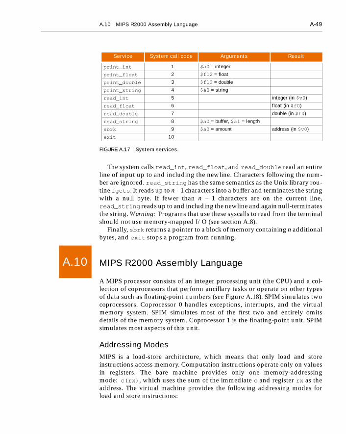
A.10 MIPS R2000 Assembly Language A-49
The system calls read_int, read_float, and read_double read an entireline of input up to and including the newline. Characters following the num-ber are ignored. read_string has the same semantics as the Unix library rou-tine fgets. It reads up to n – 1 characters into a buffer and terminates the stringwith a null byte. If fewer than n – 1 characters are on the current line,read_string reads up to and including the newline and again null-terminatesthe string. Warning: Programs that use these syscalls to read from the terminalshould not use memory-mapped I/O (see section A.8).
Finally, sbrk returns a pointer to a block of memory containing n additionalbytes, and exit stops a program from running.
A MIPS processor consists of an integer processing unit (the CPU) and a col-lection of coprocessors that perform ancillary tasks or operate on other typesof data such as floating-point numbers (see Figure A.18). SPIM simulates twocoprocessors. Coprocessor 0 handles exceptions, interrupts, and the virtualmemory system. SPIM simulates most of the first two and entirely omitsdetails of the memory system. Coprocessor 1 is the floating-point unit. SPIMsimulates most aspects of this unit.
Addressing ModesMIPS is a load-store architecture, which means that only load and storeinstructions access memory. Computation instructions operate only on valuesin registers. The bare machine provides only one memory-addressingmode: c(rx), which uses the sum of the immediate c and register rx as theaddress. The virtual machine provides the following addressing modes forload and store instructions:
Service System call code Arguments Result
print_int 01 $a0 = integer
print_float 02 $f12 = float
print_double 03 $f12 = double
print_string 04 $a0 = string
read_int 05 integer (in $v0)
read_float 06 float (in $f0) read_double 07 double (in $f0) read_string 08 $a0 = buffer, $a1 = length
sbrk 09 $a0 = amount address (in $v0)
exit 10
FIGURE A.17 System services.
A.10 MIPS R2000 Assembly Language A.10

A-50 Appendix A Assemblers, Linkers, and the SPIM Simulator
Most load and store instructions operate only on aligned data. A quantity isaligned if its memory address is a multiple of its size in bytes. Therefore, a half-word object must be stored at even addresses and a full word object must bestored at addresses that are a multiple of four. However, MIPS provides someinstructions to manipulate unaligned data (lwl, lwr, swl, and swr).
FIGURE A.18 MIPS R2000 CPU and FPU.
Format Address computation
(register) contents of register
imm immediate
imm (register) immediate + contents of register
label address of label
label ± imm address of label + or – immediate
label ± imm (register) address of label + or – (immediate + contents of register)
CPU
Registers
$0
$31
Arithmeticunit
Multiplydivide
Lo Hi
Coprocessor 1 (FPU)
Registers
$0
$31
Arithmeticunit
Registers
BadVAddr
Coprocessor 0 (traps and memory)
Status
Cause
EPC
Memory
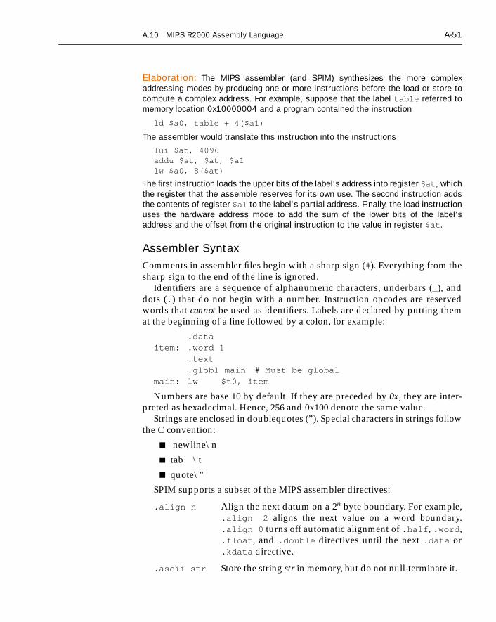
A.10 MIPS R2000 Assembly Language A-51
Elaboration: The MIPS assembler (and SPIM) synthesizes the more complexaddressing modes by producing one or more instructions before the load or store tocompute a complex address. For example, suppose that the label table referred tomemory location 0x10000004 and a program contained the instruction
ld $a0, table + 4($a1)
The assembler would translate this instruction into the instructions
lui $at, 4096addu $at, $at, $a1lw $a0, 8($at)
The first instruction loads the upper bits of the label’s address into register $at, whichthe register that the assemble reserves for its own use. The second instruction addsthe contents of register $a1 to the label’s partial address. Finally, the load instructionuses the hardware address mode to add the sum of the lower bits of the label’saddress and the offset from the original instruction to the value in register $at.
Assembler SyntaxComments in assembler files begin with a sharp sign (#). Everything from thesharp sign to the end of the line is ignored.
Identifiers are a sequence of alphanumeric characters, underbars (_), anddots (.) that do not begin with a number. Instruction opcodes are reservedwords that cannot be used as identifiers. Labels are declared by putting themat the beginning of a line followed by a colon, for example:
.dataitem: .word 1
.text
.globl main # Must be globalmain: lw $t0, item
Numbers are base 10 by default. If they are preceded by 0x, they are inter-preted as hexadecimal. Hence, 256 and 0x100 denote the same value.
Strings are enclosed in doublequotes (”). Special characters in strings followthe C convention:
■ newline\n
■ tab \t
■ quote\"
SPIM supports a subset of the MIPS assembler directives:
.align n Align the next datum on a 2n byte boundary. For example,.align 2 aligns the next value on a word boundary..align 0 turns off automatic alignment of .half, .word,.float, and .double directives until the next .data or.kdata directive.
.ascii str Store the string str in memory, but do not null-terminate it.
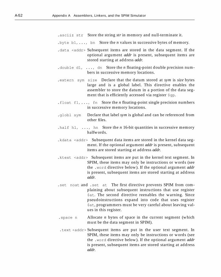
A-52 Appendix A Assemblers, Linkers, and the SPIM Simulator
.asciiz str Store the string str in memory and null-terminate it.
.byte b1,..., bn Store the n values in successive bytes of memory.
.data <addr> Subsequent items are stored in the data segment. If theoptional argument addr is present, subsequent items arestored starting at address addr.
.double d1, ..., dn Store the n floating-point double precision num-bers in successive memory locations.
.extern sym size Declare that the datum stored at sym is size byteslarge and is a global label. This directive enables theassembler to store the datum in a portion of the data seg-ment that is efficiently accessed via register $gp.
.float f1,..., fn Store the n floating-point single precision numbersin successive memory locations.
.globl sym Declare that label sym is global and can be referenced fromother files.
.half h1, ..., hn Store the n 16-bit quantities in successive memoryhalfwords.
.kdata <addr> Subsequent data items are stored in the kernel data seg-ment. If the optional argument addr is present, subsequentitems are stored starting at address addr.
.ktext <addr> Subsequent items are put in the kernel text segment. InSPIM, these items may only be instructions or words (seethe .word directive below). If the optional argument addris present, subsequent items are stored starting at addressaddr.
.set noat and .set at The first directive prevents SPIM from com-plaining about subsequent instructions that use register$at. The second directive reenables the warning. Sincepseudoinstructions expand into code that uses register$at, programmers must be very careful about leaving val-ues in this register.
.space n Allocate n bytes of space in the current segment (whichmust be the data segment in SPIM).
.text <addr> Subsequent items are put in the user text segment. InSPIM, these items may only be instructions or words (seethe .word directive below). If the optional argument addris present, subsequent items are stored starting at addressaddr.

A.10 MIPS R2000 Assembly Language A-53
.word w1,..., wn Store the n 32-bit quantities in successive memorywords.
SPIM does not distinguish various parts of the data segment (.data, .rdata,and .sdata).
Encoding MIPS InstructionsFigure A.19 explains how a MIPS instruction is encoded in a binary number.Each column contains instruction encodings for a field (a contiguous group ofbits) from an instruction. The numbers at the left margin are values for a field.For example, the j opcode has a value of 2 in the opcode field. The text at thetop of a column names a field and specifies which bits it occupies in aninstruction. For example, the op field is contained in bits 26–31 of an instruc-tion. This field encodes most instructions. However, some groups of instruc-tions use additional fields to distinguish related instructions. For example, thedifferent floating-point instructions are specified by bits 0–5. The arrows fromthe first column show which opcodes use these additional fields.
Instruction FormatThe rest of this appendix describes both the instructions implemented byactual MIPS hardware and the pseudoinstructions provided by the MIPSassembler. The two types of instructions are easily distinguished. Actualinstructions depict the fields in their binary representation. For example, in
Addition (with overflow)
the add instruction consists of six fields. Each field’s size in bits is the smallnumber below the field. This instruction begins with 6 bits of 0s. Registerspecifiers begin with an r, so the next field is a 5-bit register specifier called rs.This is the same register that is the second argument in the symbolic assemblyat the left of this line. Another common field is imm16, which is a 16-bit imme-diate number.
Pseudoinstructions follow roughly the same conventions, but omit instruc-tion encoding information. For example:
Multiply (without overflow)
In pseudoinstructions, rdest and rsrc are registers and src2 is either a reg-ister or an immediate value. In general, the assembler and SPIM translate amore general form of an instruction (e.g., add $v1, $a0, 0x55) to a special-ized form (e.g., addi $v1, $a0, 0x55).
add rd, rs, rt 0 rs rt rd 0 0x206 5 5 5 5 6
mul rdest, rsrc1, src2 pseudoinstruction

Faoetooz
IGURE A.19 MIPS opcode map. The values of each field are shown to its left. The first column shows the values in base 10nd the second shows base 16 for the op field (bits 31 to 26) in the third column. This op field completely specifies the MIPSperation except for 6 op values: 0, 1, 16, 17, 18, and 19. These operations are determined by other fields, identified by point-rs. The last field (funct) uses “f” to mean “s” if rs = 16 and op = 17 or “d” if rs = 17 and op = 17. The second field (rs) uses “z” mean “0”, “1”, “2”, or “3” if op = 16, 17, 18, or 19, respectively. If rs = 16, the operation is specified elsewhere: if z = 0, the
perations are specified in the fourth field (bits 4 to 0); if z = 1, then the operations are in the last field with f = s. If rs = 17 and = 1, then the operations are in the last field with f = d. (page A-54)
100123456789
101112131415161718192021222324252627282930313233343536373839404142434445464748495051525354555657585960616263
100123456789
101112131415161718192021222324252627282930313233343536373839404142434445464748495051525354555657585960616263
100123456789
101112131415161718192021222324252627282930313233343536373839404142434445464748495051525354555657585960616263
0123456789
10111213141516171819202122232425262728293031
0123456789
10111213141516171819202122232425262728293031
0123456789
10111213141516171819202122232425262728293031
16000102030405060708090a0b0c0d0e0 f101112131415161718191a1b1c1d1e1 f202122232425262728292a2b2c2d2e2 f303132333435363738393a3b3c3d3e3 f
op(31:26)
jjalbeqbneblezbgtzaddiaddiusltisltiuandiorixoriluiz = 0z = 1z = 2z = 3
lblhlwllwlbulhulwr
sbshswlsw
swr
lwc0lwc1lwc2lwc3
swc0swc1swc2swc3
rs(25:21)mfcz
cfcz
mtcz
ctcz
copzcopz
(16:16)bcztbczt
tlbrtlbwi
tlbwrtlbp
rte
rt (20:16)
bltzbgez
bltzalbgezal
cvt.s.fcvt.d.f
cvt.w.f
c.f.fc.un.fc.eq.fc.ueq.fc.olt.fc.ult.fc.ole.fc.ule.fc.st.fc.ngle.fc.seq.fc.ngl.fc.lt.fc.nge.fc.le.fc.ngt.f
funct(5:0)add.fsub.fmul.fdiv.f
abs.fmov.fneg.f
funct(5:0)sll
srlsra
srlvsravjrjalr
syscallbreak
mfhimthimflomtlo
multmultudivdivu
addaddusubsubuandorxornor
sltsltu
if z = l,f = d
if z = l,f = s
if z = 0
01
funct(4:0)
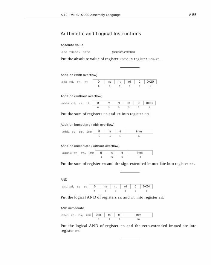
A.10 MIPS R2000 Assembly Language A-55
Arithmetic and Logical Instructions
Absolute value
Put the absolute value of register rsrc in register rdest.
Addition (with overflow)
Addition (without overflow)
Put the sum of registers rs and rt into register rd.
Addition immediate (with overflow)
Addition immediate (without overflow)
Put the sum of register rs and the sign-extended immediate into register rt.
AND
Put the logical AND of registers rs and rt into register rd.
AND immediate
Put the logical AND of register rs and the zero-extended immediate intoregister rt.
abs rdest, rsrc pseudoinstruction
add rd, rs, rt 0 rs rt rd 0 0x206 5 5 5 5 6
addu rd, rs, rt 0 rs rt rd 0 0x216 5 5 5 5 6
addi rt, rs, imm 8 rs rt imm6 5 5 16
addiu rt, rs, imm 9 rs rt imm6 5 5 16
and rd, rs, rt 0 rs rt rd 0 0x246 5 5 5 5 6
andi rt, rs, imm 0xc rs r t imm6 5 5 16

A-56 Appendix A Assemblers, Linkers, and the SPIM Simulator
Divide (with overflow)
Divide (without overflow)
Divide register rs by register rt. Leave the quotient in register lo and the re-mainder in register hi. Note that if an operand is negative, the remainder is un-specified by the MIPS architecture and depends on the convention of themachine on which SPIM is run.
Divide (with overflow)
Divide (without overflow)
Put the quotient of register rsrc1 and src2 into register rdest.
Multiply
Unsigned multiply
Multiply registers rs and rt. Leave the low-order word of the product in reg-ister lo and the high-order word in register hi.
Multiply (without overflow)
Multiply (with overflow)
div rs, rt 0 rs rt 0 0x1a6 5 5 10 6
divu rs, rt 0 rs rt 0 0x1b6 5 5 10 6
div rdest, rsrc1, src2 pseudoinstruction
divu rdest, rsrc1, src2 pseudoinstruction
mult rs, rt 0 rs r 0 0x186 5 5 10 6
multu rs, rt 0 rs r 0 0x196 5 5 10 6
mul rdest, rsrc1, src2 pseudoinstruction
mulo rdest, rsrc1, src2 pseudoinstruction
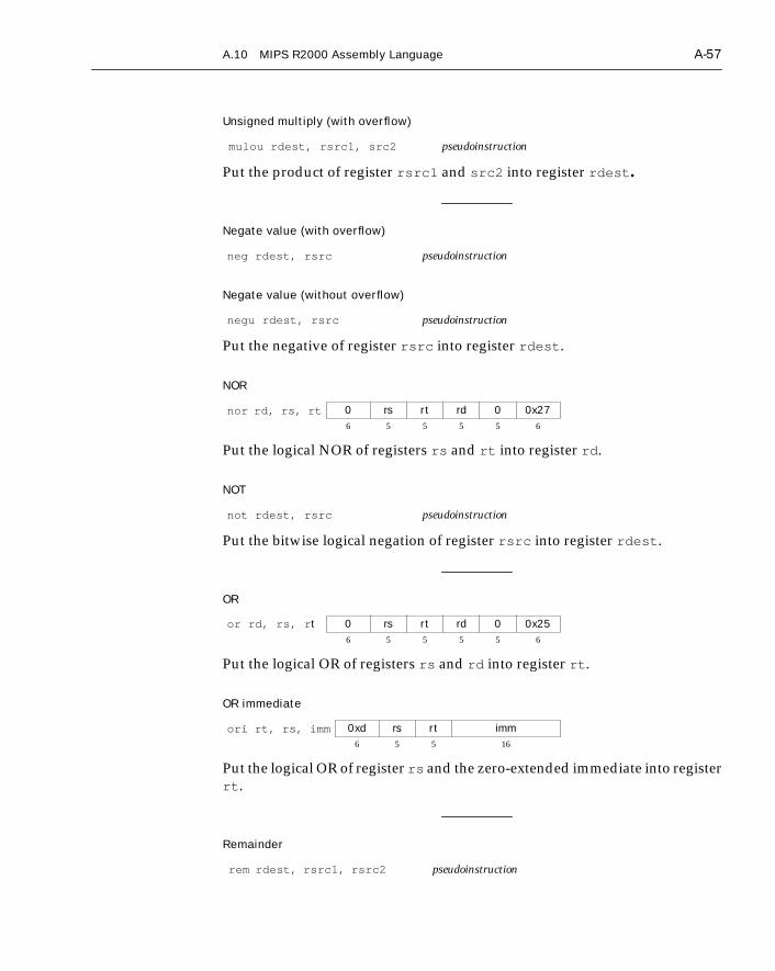
A.10 MIPS R2000 Assembly Language A-57
Unsigned multiply (with overflow)
Put the product of register rsrc1 and src2 into register rdest.
Negate value (with overflow)
Negate value (without overflow)
Put the negative of register rsrc into register rdest.
NOR
Put the logical NOR of registers rs and rt into register rd.
NOT
Put the bitwise logical negation of register rsrc into register rdest.
OR
Put the logical OR of registers rs and rd into register rt.
OR immediate
Put the logical OR of register rs and the zero-extended immediate into registerrt.
Remainder
mulou rdest, rsrc1, src2 pseudoinstruction
neg rdest, rsrc pseudoinstruction
negu rdest, rsrc pseudoinstruction
nor rd, rs, rt 0 rs rt rd 0 0x276 5 5 5 5 6
not rdest, rsrc pseudoinstruction
or rd, rs, rt 0 rs r t rd 0 0x256 5 5 5 5 6
ori rt, rs, imm 0xd rs r t imm6 5 5 16
rem rdest, rsrc1, rsrc2 pseudoinstruction

A-58 Appendix A Assemblers, Linkers, and the SPIM Simulator
Unsigned remainder
Put the remainder of register rsrc1 divided by register rsrc2 into registerrdest. Note that if an operand is negative, the remainder is unspecified by theMIPS architecture and depends on the convention of the machine on whichSPIM is run.
Shift left logical
Shift left logical variable
Shift right arithmetic
Shift right arithmetic variable
Shift right logical
Shift right logical variable
Shift register rt left (right) by the distance indicated by immediate sa or theregister rs and put the result in register rd.
Rotate left
remu rdest, rsrc1, rsrc2 pseudoinstruction
sll rd, rt, shamt 0 rs rt rd shamt 06 5 5 5 5 6
sllv rd, rt, rs 0 rs rt rd 0 46 5 5 5 5 6
sra rd, rt, shamt 0 Rs Rt Rd shamt 36 5 5 5 5 6
srav rd, rt, rs 0 rs rt rd 0 76 5 5 5 5 6
srl rd, rt, shamt 0 rs rt rd shamt 26 5 5 5 5 6
srlv rd, rt, rs 0 rs rt rd 0 66 5 5 5 5 6
rol rdest, rsrc1, rsrc2 pseudoinstruction
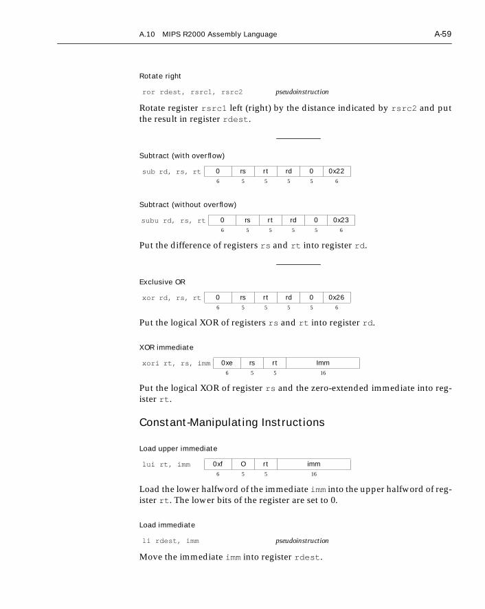
A.10 MIPS R2000 Assembly Language A-59
Rotate right
Rotate register rsrc1 left (right) by the distance indicated by rsrc2 and putthe result in register rdest.
Subtract (with overflow)
Subtract (without overflow)
Put the difference of registers rs and rt into register rd.
Exclusive OR
Put the logical XOR of registers rs and rt into register rd.
XOR immediate
Put the logical XOR of register rs and the zero-extended immediate into reg-ister rt.
Constant-Manipulating Instructions
Load upper immediate
Load the lower halfword of the immediate imm into the upper halfword of reg-ister rt. The lower bits of the register are set to 0.
Load immediate
Move the immediate imm into register rdest.
ror rdest, rsrc1, rsrc2 pseudoinstruction
sub rd, rs, rt 0 rs rt rd 0 0x226 5 5 5 5 6
subu rd, rs, rt 0 rs rt rd 0 0x236 5 5 5 5 6
xor rd, rs, rt 0 rs rt rd 0 0x266 5 5 5 5 6
xori rt, rs, imm 0xe rs r t Imm6 5 5 16
lui rt, imm 0xf O rt imm6 5 5 16
li rdest, imm pseudoinstruction

A-60 Appendix A Assemblers, Linkers, and the SPIM Simulator
Comparison Instructions
Set less than
Set less than unsigned
Set register rd to 1 if register rs is less than rt, and to 0 otherwise.
Set less than immediate
Set less than unsigned immediate
Set register rd to 1 if register rs is less than the sign-extended immediate, andto 0 otherwise.
Set equal
Set register rdest to 1 if register rsrc1 equals rsrc2, and to 0 otherwise.
Set greater than equal
Set greater than equal unsigned
Set register rdest to 1 if register rsrc1 is greater than or equal to rsrc2, andto 0 otherwise.
slt rd, rs, rt 0 rs rt rd 0 0x2a6 5 5 5 5 6
sltu rd, rs, rt 0 rs rt rd 0 0x2b6 5 5 5 5 6
slti rd, rs, imm 0xa rs rd imm6 5 5 16
sltiu rd, rs, imm 0xb rs rd imm6 5 5 16
seq rdest, rsrc1, rsrc2 pseudoinstruction
sge rdest, rsrc1, rsrc2 pseudoinstruction
sgeu rdest, rsrc1, rsrc2 pseudoinstruction
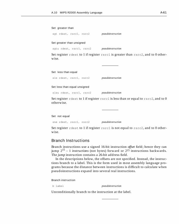
A.10 MIPS R2000 Assembly Language A-61
Set greater than
Set greater than unsigned
Set register rdest to 1 if register rsrc1 is greater than rsrc2, and to 0 other-wise.
Set less than equal
Set less than equal unsigned
Set register rdest to 1 if register rsrc1 is less than or equal to rsrc2, and to 0otherwise.
Set not equal
Set register rdest to 1 if register rsrc1 is not equal to rsrc2, and to 0 other-wise.
Branch InstructionsBranch instructions use a signed 16-bit instruction offset field; hence they canjump 215 – 1 instructions (not bytes) forward or 215 instructions backwards.The jump instruction contains a 26-bit address field.
In the descriptions below, the offsets are not specified. Instead, the instruc-tions branch to a label. This is the form used in most assembly language pro-grams because the distance between instructions is difficult to calculate whenpseudoinstructions expand into several real instructions.
Branch instruction
Unconditionally branch to the instruction at the label.
sgt rdest, rsrc1, rsrc2 pseudoinstruction
sgtu rdest, rsrc1, rsrc2 pseudoinstruction
sle rdest, rsrc1, rsrc2 pseudoinstruction
sleu rdest, rsrc1, rsrc2 pseudoinstruction
sne rdest, rsrc1, rsrc2 pseudoinstruction
b label pseudoinstruction

A-62 Appendix A Assemblers, Linkers, and the SPIM Simulator
Branch coprocessor z true
Branch coprocessor z false
Conditionally branch the number of instructions specified by the offset if z’scondition flag is true (false). z is 0, 1, 2, or 3. The floating-point unit is z = 1.
Branch on equal
Conditionally branch the number of instructions specified by the offset ifregister rs equals rt.
Branch on greater than equal zero
Conditionally branch the number of instructions specified by the offset ifregister rs is greater than or equal to 0.
Branch on greater than equal zero and link
Conditionally branch the number of instructions specified by the offset ifregister rs is greater than or equal to 0. Save the address of the next instructionin register 31.
Branch on greater than zero
Conditionally branch the number of instructions specified by the offset ifregister rs is greater than 0.
bczt label 0x1z 8 1 Offset6 5 5 16
bczf label 0x1z 8 0 Offset6 5 5 16
beq Rs, Rt, label 4 Rs Rt Offset6 5 5 16
bgez rs, label 1 Rs 1 Offset6 5 5 16
bgezal rs,label 1 rs 0x11 Offset6 5 5 16
bgtz rs, label 7 rs 0 Offset6 5 5 16
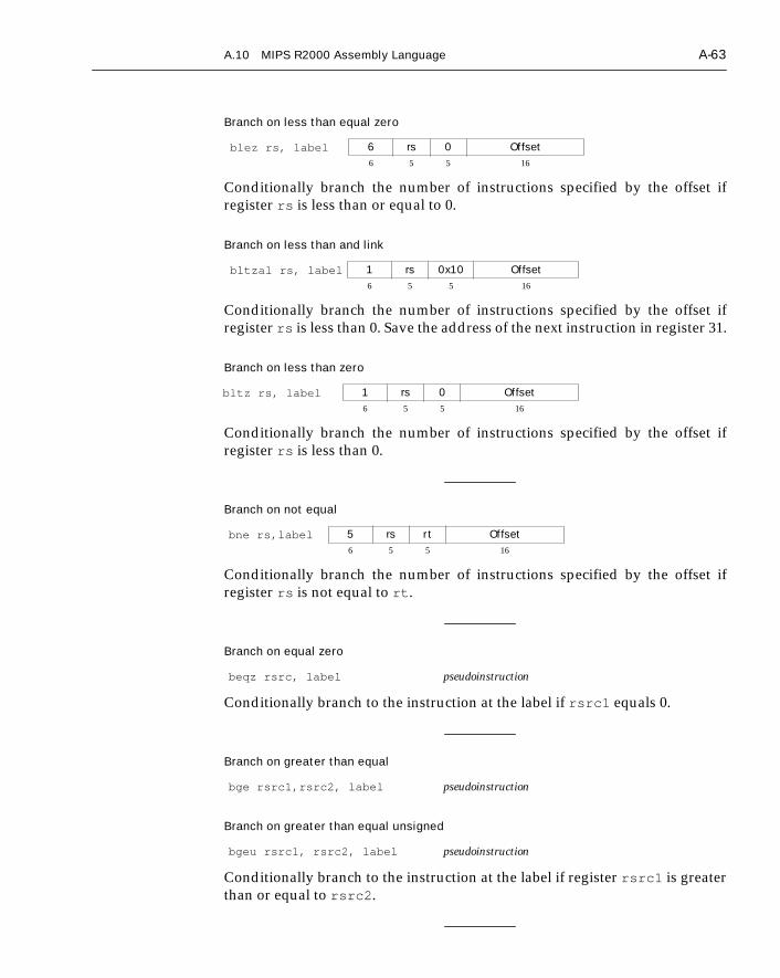
A.10 MIPS R2000 Assembly Language A-63
Branch on less than equal zero
Conditionally branch the number of instructions specified by the offset ifregister rs is less than or equal to 0.
Branch on less than and link
Conditionally branch the number of instructions specified by the offset ifregister rs is less than 0. Save the address of the next instruction in register 31.
Branch on less than zero
Conditionally branch the number of instructions specified by the offset ifregister rs is less than 0.
Branch on not equal
Conditionally branch the number of instructions specified by the offset ifregister rs is not equal to rt.
Branch on equal zero
Conditionally branch to the instruction at the label if rsrc1 equals 0.
Branch on greater than equal
Branch on greater than equal unsigned
Conditionally branch to the instruction at the label if register rsrc1 is greaterthan or equal to rsrc2.
blez rs, label 6 rs 0 Offset6 5 5 16
bltzal rs, label 1 rs 0x10 Offset6 5 5 16
bltz rs, label 1 rs 0 Offset6 5 5 16
bne rs,label 5 rs rt Offset6 5 5 16
beqz rsrc, label pseudoinstruction
bge rsrc1,rsrc2, label pseudoinstruction
bgeu rsrc1, rsrc2, label pseudoinstruction
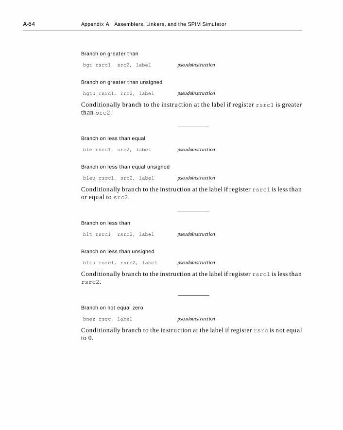
A-64 Appendix A Assemblers, Linkers, and the SPIM Simulator
Branch on greater than
Branch on greater than unsigned
Conditionally branch to the instruction at the label if register rsrc1 is greaterthan src2.
Branch on less than equal
Branch on less than equal unsigned
Conditionally branch to the instruction at the label if register rsrc1 is less thanor equal to src2.
Branch on less than
Branch on less than unsigned
Conditionally branch to the instruction at the label if register rsrc1 is less thanrsrc2.
Branch on not equal zero
Conditionally branch to the instruction at the label if register rsrc is not equalto 0.
bgt rsrc1, src2, label pseudoinstruction
bgtu rsrc1, rrc2, label pseudoinstruction
ble rsrc1, src2, label pseudoinstruction
bleu rsrc1, src2, label pseudoinstruction
blt rsrc1, rsrc2, label pseudoinstruction
bltu rsrc1, rsrc2, label pseudoinstruction
bnez rsrc, label pseudoinstruction
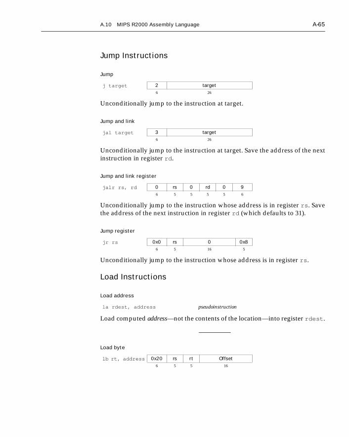
A.10 MIPS R2000 Assembly Language A-65
Jump Instructions
Jump
Unconditionally jump to the instruction at target.
Jump and link
Unconditionally jump to the instruction at target. Save the address of the nextinstruction in register rd.
Jump and link register
Unconditionally jump to the instruction whose address is in register rs. Savethe address of the next instruction in register rd (which defaults to 31).
Jump register
Unconditionally jump to the instruction whose address is in register rs.
Load Instructions
Load address
Load computed address—not the contents of the location—into register rdest.
Load byte
j target 2 target6 26
jal target 3 target6 26
jalr rs, rd 0 rs 0 rd 0 96 5 5 5 5 6
jr rs 0x0 rs 0 0x86 5 16 5
la rdest, address pseudoinstruction
lb rt, address 0x20 rs rt Offset6 5 5 16

A-66 Appendix A Assemblers, Linkers, and the SPIM Simulator
Load unsigned byte
Load the byte at address into register rt. The byte is sign-extended by lb, butnot by lbu.
Load halfword
Load unsigned halfword
Load the 16-bit quantity (halfword) at address into register tt. The halfword issign-extended by lh, but not by lhu.
Load word
Load the 32-bit quantity (word) at address into register rt.
Load word coprocessor
Load the word at address into register rt of coprocessor z (0–3). The floating-point unit is z = 1.
Load word left
Load word right
Load the left (right) bytes from the word at the possibly unaligned address intoregister rt.
lbu rt, address 0x24 rs rt Offset6 5 5 16
lh rt, address 0x21 rs rt Offset6 5 5 16
lhu rt, address 0x25 rs rt Offset6 5 5 16
lw rt, address 0x23 rs rt Offset6 5 5 16
lwcz rt, address 0x3z rs r t Offset6 5 5 16
lwl rt, address 0x22 rs rt Offset6 5 5 16
lwr Rt, address 0x23 Rs Rt Offset6 5 5 16

A.10 MIPS R2000 Assembly Language A-67
Load doubleword
Load the 64-bit quantity at address into registers rdest and rdest + 1.
Unaligned load halfword
Unaligned load halfword unsigned
Load the 16-bit quantity (halfword) at the possibly unaligned address intoregister rdest. The halfword is sign-extended by ulh, but not ulhu.
Unaligned load word
Load the 32-bit quantity (word) at the possibly unaligned address into registerrdest.
Store Instructions
Store byte
Store the low byte from register rt at address.
Store halfword
Store the low halfword from register rt at address.
Store word
Store the word from register rt at address.
ld rdest, address pseudoinstruction
ulh rdest, address pseudoinstruction
ulhu rdest, address pseudoinstruction
ulw rdest, address pseudoinstruction
sb rt, address 0x28 rs rt Offset6 5 5 16
sh rt, address 0x29 rs rt Offset6 5 5 16
sw rt, address 0x2b rs r t Offset6 5 5 16

A-68 Appendix A Assemblers, Linkers, and the SPIM Simulator
Store word coprocessor
Store the word from register rt of coprocessor z at address. The floating pointunit is z = 1.
Store word left
Store word right
Store the left (right) bytes from register rt at the possibly unaligned address.
Store doubleword
Store the 64-bit quantity in registers rsrc and rsrc + 1 at address.
Unaligned store halfword
Store the low halfword from register rsrc at the possibly unaligned address.
Unaligned store word
Store the word from register rsrc at the possibly unaligned address.
Data Movement Instructions
Move
Move register rsrc to rdest.
Move from hi
swcz rt, address 0x3(1-z) rs r t Offset6 5 5 16
swl rt, address 0x2a rs r t Offset6 5 5 16
swr rt, address 0x2e rs r t Offset 6 5 5 16
sd rsrc, address pseudoinstruction
ush rsrc, address pseudoinstruction
usw rsrc, address pseudoinstruction
move rdest, rsrc pseudoinstruction
mfhi rd 0 0 rd 0 0x106 10 5 5 6
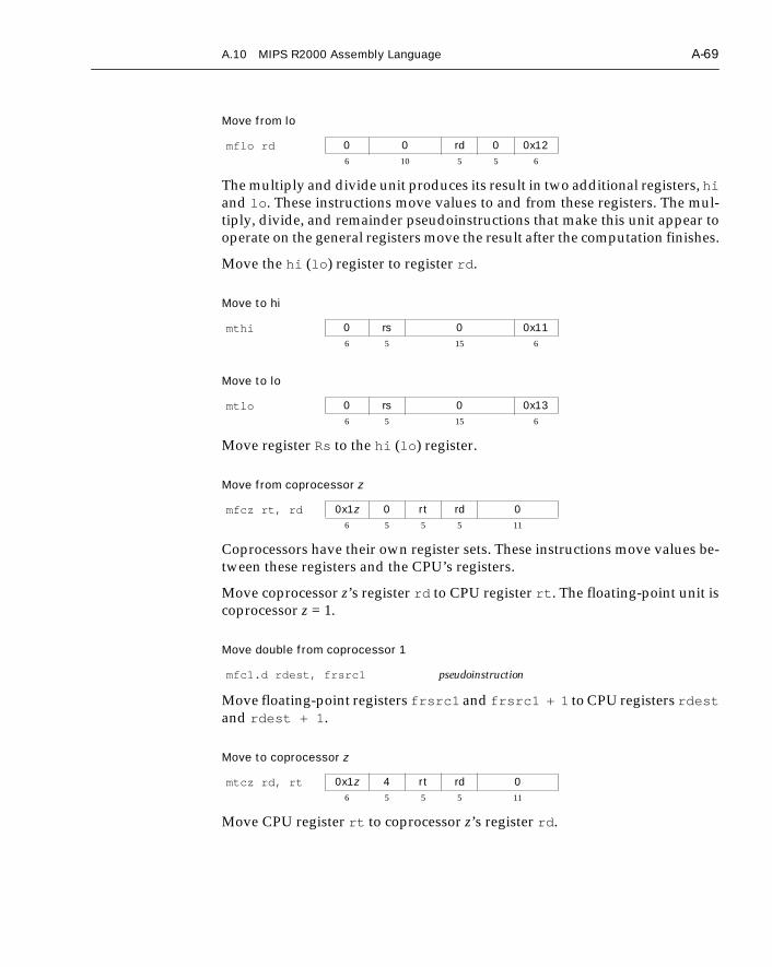
A.10 MIPS R2000 Assembly Language A-69
Move from lo
The multiply and divide unit produces its result in two additional registers, hiand lo. These instructions move values to and from these registers. The mul-tiply, divide, and remainder pseudoinstructions that make this unit appear tooperate on the general registers move the result after the computation finishes.
Move the hi (lo) register to register rd.
Move to hi
Move to lo
Move register Rs to the hi (lo) register.
Move from coprocessor z
Coprocessors have their own register sets. These instructions move values be-tween these registers and the CPU’s registers.
Move coprocessor z’s register rd to CPU register rt. The floating-point unit iscoprocessor z = 1.
Move double from coprocessor 1
Move floating-point registers frsrc1 and frsrc1 + 1 to CPU registers rdestand rdest + 1.
Move to coprocessor z
Move CPU register rt to coprocessor z’s register rd.
mflo rd 0 0 rd 0 0x126 10 5 5 6
mthi 0 rs 0 0x116 5 15 6
mtlo 0 rs 0 0x136 5 15 6
mfcz rt, rd 0x1z 0 rt rd 06 5 5 5 11
mfc1.d rdest, frsrc1 pseudoinstruction
mtcz rd, rt 0x1z 4 rt rd 06 5 5 5 11
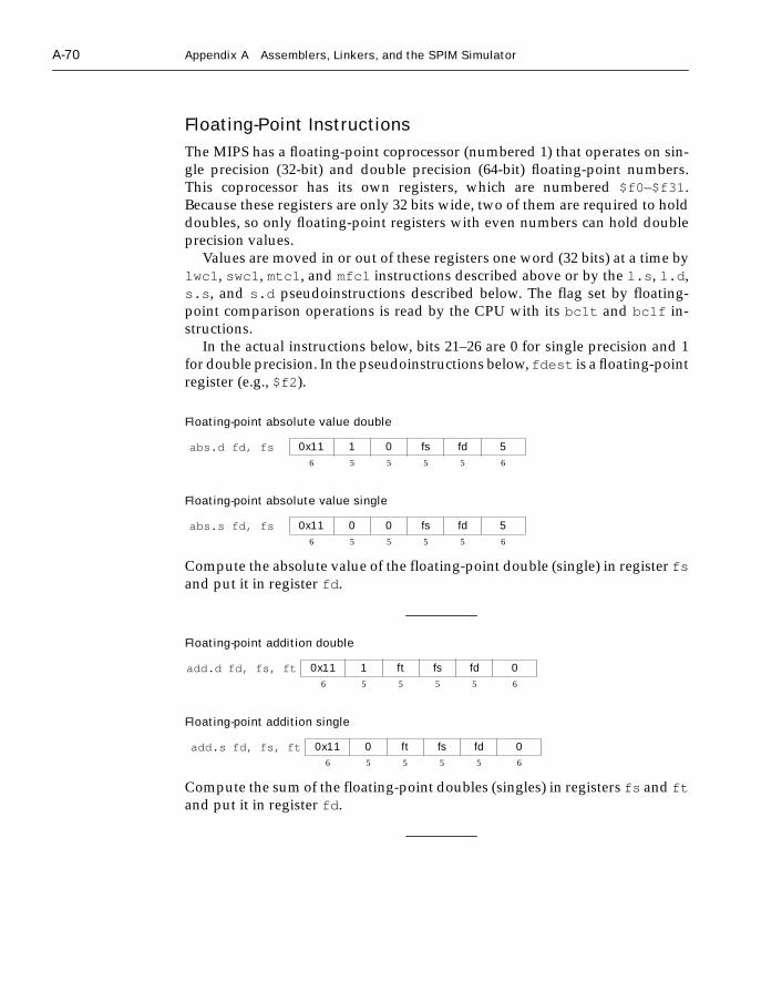
A-70 Appendix A Assemblers, Linkers, and the SPIM Simulator
Floating-Point InstructionsThe MIPS has a floating-point coprocessor (numbered 1) that operates on sin-gle precision (32-bit) and double precision (64-bit) floating-point numbers.This coprocessor has its own registers, which are numbered $f0–$f31.Because these registers are only 32 bits wide, two of them are required to holddoubles, so only floating-point registers with even numbers can hold doubleprecision values.
Values are moved in or out of these registers one word (32 bits) at a time bylwc1, swc1, mtc1, and mfc1 instructions described above or by the l.s, l.d,s.s, and s.d pseudoinstructions described below. The flag set by floating-point comparison operations is read by the CPU with its bc1t and bc1f in-structions.
In the actual instructions below, bits 21–26 are 0 for single precision and 1for double precision. In the pseudoinstructions below, fdest is a floating-pointregister (e.g., $f2).
Floating-point absolute value double
Floating-point absolute value single
Compute the absolute value of the floating-point double (single) in register fsand put it in register fd.
Floating-point addition double
Floating-point addition single
Compute the sum of the floating-point doubles (singles) in registers fs and ftand put it in register fd.
abs.d fd, fs 0x11 1 0 fs fd 56 5 5 5 5 6
abs.s fd, fs 0x11 0 0 fs fd 56 5 5 5 5 6
add.d fd, fs, ft 0x11 1 ft fs fd 06 5 5 5 5 6
add.s fd, fs, ft 0x11 0 ft fs fd 06 5 5 5 5 6

A.10 MIPS R2000 Assembly Language A-71
Compare equal double
Compare equal single
Compare the floating-point double in register fs against the one in ft and setthe floating-point condition flag true if they are equal. Use the bc1t or bc1finstructions to test the value of this flag.
Compare less than equal double
Compare less than equal single
Compare the floating-point double in register fs against the one in ft and setthe floating-point condition flag true if the first is less than or equal to the sec-ond. Use the bc1t or bc1f instructions to test the value of this flag.
Compare less than double
Compare less than single
Compare the floating-point double in register fs against the one in ft and setthe condition flag true if the first is less than the second. Use the bc1t or bc1finstructions to test the value of this flag.
Convert single to double
c.eq.d fs, ft 0x11 1 ft fs fd FC 26 5 5 5 5 2 4
c.eq.s fs, ft 0x11 0 ft fs fd FC 26 5 5 5 5 2 4
c.le.d fs, ft 0x11 1 ft fs 0 FC 26 5 5 5 5 2 4
c.le.s fs, ft 0x11 0 ft fs 0 FC 26 5 5 5 5 2 4
c.lt.d fs, ft 0x11 1 ft fs 0 FC 0xc6 5 5 5 5 2 4
c.lt.s fs, ft 0x11 0 ft fs 0 FC 0xc6 5 5 5 5 2 4
cvt.d.s fd, fs 0x11 1 0 fs fd 0x216 5 5 5 5 6

A-72 Appendix A Assemblers, Linkers, and the SPIM Simulator
Convert integer to double
Convert the single precision floating-point number or integer in register fs toa double precision number and put it in register fd.
Convert double to single
Convert integer to single
Convert the double precision floating-point number or integer in register fs toa single precision number and put it in register fd.
Convert double to integer
Convert single to integer
Convert the double or single precision floating-point number in register fs toan integer and put it in register fd.
Floating-point divide double
Floating-point divide single
Compute the quotient of the floating-point doubles (singles) in registers fsand ft and put it in register fd.
cvt.d.w fd, fs 0x11 0 0 fs fd 0x216 5 5 5 5 6
cvt.s.d fd, fs 0x11 1 0 Fs Fd 0x206 5 5 5 5 6
cvt.s.w fd, fs 0x11 0 0 fs fd 0x206 5 5 5 5 6
cvt.w.d fd, fs 0x11 1 0 fs fd 0x246 5 5 5 5 6
cvt.w.s fd, fs 0x11 0 0 fs fd 0x246 5 5 5 5 6
div.d fd, fs, ft 0x11 1 ft fs fd 36 5 5 5 5 6
div.s fd, fs, ft 0x11 0 ft fs fd 36 5 5 5 5 6

A.10 MIPS R2000 Assembly Language A-73
Load floating-point double
Load floating-point single
Load the floating-point double (single) at address into register fdest.
Move floating-point double
Move floating-point single
Move the floating-point double (single) from register fs to register fd.
Floating-point multiply double
Floating-point multiply single
Compute the product of the floating-point doubles (singles) in registers fs andft and put it in register fd.
Negate double
Negate single
Negate the floating-point double (single) in register fs and put it in register fd.
l.d fdest, address pseudoinstruction
l.s fdest, address pseudoinstruction
mov.d fd, fs 0x11 1 0 fs fd 66 5 5 5 5 6
mov.s fd, fs 0x11 0 0 fs fd 66 5 5 5 5 6
mul.d fd, fs, ft 0x11 1 ft fs fd 26 5 5 5 5 6
mul.s fd, fs, ft 0x11 0 ft fs fd 26 5 5 5 5 6
neg.d fd, fs 0x11 1 ft fs fd 76 5 5 5 5 6
neg.s fd, fs 0x11 0 ft fs fd 76 5 5 5 5 6

A-74 Appendix A Assemblers, Linkers, and the SPIM Simulator
Store floating-point double
Store floating-point single
Store the floating-point double (single) in register dest at address.
Floating-point subtract double
Floating-point subtract single
Compute the difference of the floating-point doubles (singles) in registers fsand ft and put it in register fd.
Exception and Interrupt Instructions
Return from exception
Restore the Status register.
System call
Register $v0 contains the number of the system call (see Figure A.17) providedby SPIM.
s.d fdest, address pseudoinstruction
s.s fdest, address pseudoinstruction
sub.d fd, fs, ft 0x11 1 ft fs fd 16 5 5 5 5 6
sub.s fd, fs, ft 0x11 0 ft fs fd 16 5 5 5 5 6
rfe 0x10 1 0 0x206 1 19 6
syscall 0 0 0xc6 20 6

A.11 Concluding Remarks A-75
Break
Cause exception code. Exception 1 is reserved for the debugger.
No operation
Do nothing.
Programming in assembly language requires a programmer to trade off help-ful features of high-level languages—such as data structures, type checking,and control constructs—for complete control over the instructions that a com-puter executes. External constraints on some applications, such as responsetime or program size, require a programmer to pay close attention to everyinstruction. However, the cost of this level of attention is assembly languageprograms that are longer, more time-consuming to write, and more difficult tomaintain than high-level language programs.
Moreover, three trends are reducing the need to write programs in assemblylanguage. The first trend is toward the improvement of compilers. Moderncompilers produce code that is typically comparable to the best handwrittencode and is sometimes better. The second trend is the introduction of new pro-cessors that are not only faster, but in the case of processors that execute mul-tiple instructions simultaneously, also more difficult to program by hand. Inaddition, the rapid evolution of the modern computer favors high-level lan-guage programs that are not tied to a single architecture. Finally, we witness atrend toward increasingly complex applications—characterized by complexgraphic interfaces and many more features than their predecessors. Large ap-plications are written by teams of programmers and require the modularityand semantic checking features provided by high-level languages.
To Probe Further
Kane, G., and J. Heinrich [1992]. MIPS RISC Architecture, Prentice Hall, Englewood Cliffs, NJ.
The last word on the MIPS instruction set and assembly language programming on these machines.
Aho, A., R. Sethi, and J. Ullman [1985]. Compilers: Principles, Techniques, and Tools, Addison-Wesley, Reading, MA.
Slightly dated and lacking in coverage of modern architectures, but still the standard reference on compilers.
break 0 code 0xd6 20 6
nop 0 0 0 0 0 06 5 5 5 5 6
A.11 Concluding Remarks A.11
A-76 Appendix A Assemblers, Linkers, and the SPIM Simulator
A number of key terms have been introduced in this appendix. Check theGlossary for definitions of terms you are uncertain of.
A.1 [5] <§A.5> Section A.5 described how memory is partitioned on mostMIPS systems. Propose another way of dividing memory that meets the samegoals.
A.2 [20] <§A.6> Rewrite the code for fact to use fewer instructions.
A.3 [5] <§A.7> Is it ever safe for a user program to use registers $k0 or $k1?
A.4 [25] <§A.7> Section A.7 contains code for a very simple exception han-dler. One serious problem with this handler is that it disables interrupts for along time. This means that interrupts from a fast I/O device may be lost. Writea better exception handler that is interruptable and enables interrupts as quick-ly as possible.
A.5 [15] <§A.7> The simple exception handler always jumps back to the in-struction following the exception. This works fine unless the instruction thatcauses the exception is in the delay slot of a branch. In that case, the next in-struction is the target of the branch. Write a better handler that uses the EPCregister to determine which instruction should be executed after the exception.
A.6 [5] <§A.9> Using SPIM, write and test an adding machine program thatrepeatedly reads in integers and adds them into a running sum. The programshould stop when it gets an input that is 0, printing out the sum at that point.Use the SPIM system calls described on pages A-48 and A-49.
A.12 Key Terms A.12
A.13 Exercises A.13
absolute addressassembler directivebackpatchingcallee-saved registercaller-saved registerdata segmentexternal or global labelformal parameterforward reference
interrupt handlerlocal labelmachine languagemacrosprocedure call or stack framerecursive proceduresregister-use or procedure-call
conventionrelocation information
separate compilationsource languagestack segmentstatic datasymbol tabletext segmentunresolved referencevirtual machine

A.13 Exercises A-77
A.7 [5] <§A.9> Using SPIM, write and test a program that reads in three inte-gers and prints out the sum of the largest two of the three. Use the SPIM systemcalls described on pages A-48 and A-49. You can break ties arbitrarily.
A.8 [5] <§A.9> Using SPIM, write and test a program that reads in a positiveinteger using the SPIM system calls. If the integer is not positive, the programshould terminate with the message “Invalid Entry”; otherwise the programshould print out the names of the digits of the integers, delimited by exactlyone space. For example, if the user entered “728,” the output would be “SevenTwo Eight.”
A.9 [25] <§A.9> Write and test a MIPS assembly language program to com-pute and print the first 100 prime numbers. A number n is prime if no numbersexcept 1 and n divide it evenly. You should implement two routines:
■ test_prime (n) Return 1 if n is prime and 0 if n is not prime.
■ main () Iterate over the integers, testing if each is prime. Print thefirst 100 numbers that are prime.
Test your programs by running them on SPIM.
A.10 A.10 [10] <§§A.6, A.9> Using SPIM, write and test a recursive programfor solving the classic mathematical recreation, the Towers of Hanoi puzzle.(This will require the use of stack frames to support recursion.) The puzzleconsists of three pegs (1, 2, and 3) and n disks (the number n can vary; typicalvalues might be in the range from 1 to 8). Disk 1 is smaller than disk 2, whichis in turn smaller than disk 3, and so forth, with disk n being the largest. Initial-ly, all the disks are on peg 1, starting with disk n on the bottom, disk n – 1 ontop of that, and so forth, up to disk 1 on the top. The goal is to move all thedisks to peg 2. You may only move one disk at a time, that is, the top disk fromany of the three pegs onto the top of either of the other two pegs. Moreover,there is a constraint: You must not place a larger disk on top of a smaller disk.
The C program on the next page can be used to help write your assembly lan-guage program.
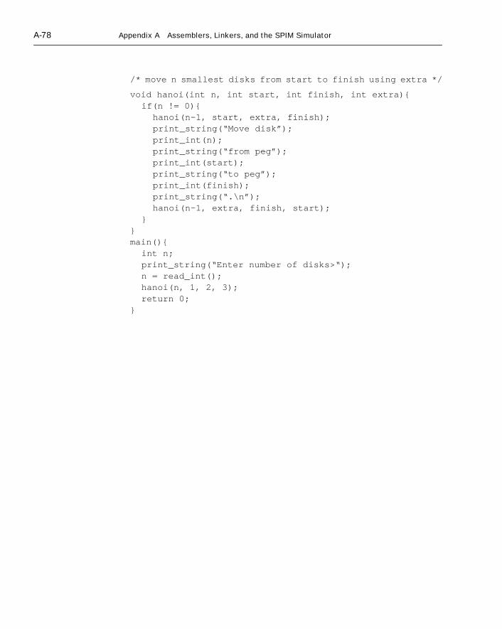
A-78 Appendix A Assemblers, Linkers, and the SPIM Simulator
/* move n smallest disks from start to finish using extra */
void hanoi(int n, int start, int finish, int extra){if(n != 0){
hanoi(n-1, start, extra, finish);print_string(“Move disk”);print_int(n);print_string(“from peg”);print_int(start);print_string(“to peg”);print_int(finish);print_string(“.\n”);hanoi(n-1, extra, finish, start);
}}main(){
int n;print_string(“Enter number of disks>“);n = read_int();hanoi(n, 1, 2, 3);return 0;
}
