appendix b - marked-up affected teciinical- …
TRANSCRIPT

,
.
-
Attachment to.
'
NSD940428
APPENDIX B - MARKED-UP AFFECTED TECIINICAL- SPECIFICATION PAGES
..
.
|9405020374 940426 '
PDR ADOCK 05000298P PDR

COOPER , 2AR STATION "P '[9<.f'/' k -*~q
.w y4 e .TABLE 3.2.F == -- -
-
PRIMARY CONTAINMENT SURVEILIANC ATION %,
All ' Y'Minimum Number Action Required When
'
Instrument ofCoperable Minimum condition-Instrument I.D. No. Range (Instrument ~ Channels Not Satisfied (1)
Reactor Vater Level NBI-LI-85A E-150)< to +604 i=W.~ 2'
A,B,C
NBI-LI-85B -150X to 460K /"6
Reactor Pressure RFC-PI-90A O y 1200 psig 2 A,B,C,
RFC-PI-90B X 1200 psig
Drywell Pressure PC-PR-2A -5 to 70 psig 2 A,B,C [
PC-PR-2B -5 to 70 psig-
-PC-PR-1A 0 X 250 psig 2 F
PC-PR-1B 0 f 250 psig
Drywell Temperature PC-TR-50 50p)( 170*F 2 A,B,C
A,B.C.D.E 50 ")( 350*F
2 A,B,C
44)X 300*F4 Suppression Chamber / Torus PC-TR-21A0 ( 400*F.y ' Air Temperature PC-TR-23, Der 1 6 2
Suppression Chamber / Torus PC-TR-24, Det la to lh X 250*F 1 (2) Note 2
Water Temperature PC-TR-25, Det 2a to 2h 0 )( 250*F ,
Suppression Chamber / Torus .
1- Water Level PC-LI-10 l-4X to +63) A f 2 A,B,C
PC-LR-11 1-4X to +6M)t At'
PC-LI-12 -10k to +104 /m4e 2 A,B,C,E
PC-LI-13 -10M to +1 @ /=6ePC-LR-1A 0 x 3'0GAv. - 2 F
PC-LR-1B 0 g 30'N h t
Suppression Chamber / Torus PC-PR-20 0 g 2'psig- 1 B,C
Pressure g'
Control Rod Position' N.A. Indicating Lights 1 A,B,C,D
h< >
t Neutron Monitoring N.A. S.R.M., I.R.M.', 1 A,B,C,D
v.- LPax - q::; af __
bi & u4A s. m a.2.e| #'M * 0? n'~2 Wh,,=,?$$,?,"$Yhd k "!v& &~$ W h|C " {_ ,. _ . . __ m. Pc-,,,C m ,m , 1= 2m 3, C . y ;.
.,
:y:'~
0 Various.-
pC: ::ntratinn . "C tJ:/CC-!! /C22
. - , . .. , - - .. - - . , . . . - .. -

_
.
|.
STES FOR TABL.E 3.2.F- hMy ckeht.u d -f. u m ( AII WL o11owin5 actions.will be taken if the minimum number of operable instrumentf~1.
channels)asrequiredarenotavailable.pg hg.D 4.0 CAh~
-- --_
A. From and after the da __ thac .one of these - parameters is reduced to oneindication, continued 5perati.on31s permissible during the succeeding thirty
_
-
days unless such(instrumTntaY1'o'n)is sooner made operable.1gcAcv.e. ton EQ.atcAts~
.
B. From and after the date t one of these parameters is not indicated in thecontrol. room, continued {i6peration)is permissible du ing the succeeding sevendays unless such @ enta_ti @ is sooner made perab .
_
C. If the requirements of A and B above cannot be met, an orderly 6hutdow3rshall be initiated within 24 hours.
D. These surveillance instruments are considered to be redundant to each other,9
E. In the event that both channels are inoperable and indication cannot berestored in six (6) hours. an orderlyQhutdown3 shall be initiated and thereactor shall be in Got Shutdog in six'(6) hours and in a'@oTd Shutdow]ncondition in the following eighteen (18) hours.
,
F. From and after the date that one of these parameters 'is reduced to oneindication, .either restore the inoperabla component (s) to (operable) statuswithin 30 days of the event, or prepare and submit a Special . Report to.theCommission outlining the action taken, the cause of the inoperability - and -the plans and schedule for restoring the system to 6 parable?) status. In the
event that both channels are inoperable and indication cannot be restored infourteen (14) days, an orderly shall be initiated.
2. Each channel contains eight detectors. .A channel is considered inoperable if two
adjacent detectors are unmonitored by the. channel in question.. E Act *8. foWE.O M C A h
A. From and after the . date ' that one channel becomes inoperable., continuedc+ operatioib is permissible during the succeeding seven days unless sooner made
B. From and after the date that the second channel becomes inoperable, an l
orderly Q shall be initiated within 48 hours unless sooner . madeM_ ~
2A % ve3. During periods when both . channe s are 1 operable, grab samples may.be taken to 4
I"- : 1verify primary containment oxygen concentration.- _- |
1
Ma s' A kb We b b Webu Redt0A .bAP S 7b,a. cW
|
1
~6b ;;iu|=
. .- - - = , ,

-
COOPER NUCLEAR STATIONTABLE 3.2.H *
POST-ACCIDENT MONITORING INSTRUMENTATION REQUIREMENTS * All df'-Miniinun Number of Action Required When
Instrument Qerable_Instrumen" Camponent(0nerabt tty~
Instrument ID Number Rance O'hannel s) Is Not Assured
Elevated Release Point (ERP) RMP-RM-3B 1.00E-2 to 1 (Note 1) A'Monitor (High Range Noble l.00E+5 pc/cc
Cas) (Xe-133 *
Equivalent)
Turbine Building Ventilation RMV-RM-20B 1.00E-2 to 1 (Note 1) AExhaust Monitor 1.00Et5 pc/cc(Iligh Range Noble Gac) (Xe-133
Equivalent)
Radwaste/ Augmented Radwaste RMV-RM-30B 1.00E-2 to 1 (Note 1) AExhaust Monitor 1.00E+5 pc/cc.
-0 (liigh Range Noble Gas) (Xe-133 I.
T Equivalent)
Primary Containment Gross RMA-RM-40A 1.0-1.0E+7 R/Hr. 2 (Note 1) ARadiation Monitor RMA-RM-40B 0-1.0EF R Hr.
1-L Lee o,wi[4Primary Containment "ydroge:' PC-AN-il /0 I OI'to 30% o - t o 7. - 2 (Notes 1 cr' 2) B {
~
>2 2
Concentration Analyzer PC- AN-H /0 1I 0% to 30% o t o y, <
2 2
23 A^d hMptA Crygts .
Other Post-Accident Monitoring Instrumentation is located in Table 3.2.F-Drywell' Pressure, PC-PR-1A and IB, Suppression Chamber / Torus Water Level PC-LR-1A and IB $
$; wi e
w;
i
%-
!! ka #
-. -. - - _ -_

;, .
.
4 y
- NOTES FOR TABLE 3,2.H
G ridd ar_deO ~d. 4.r % (f l ( M4fAction:
A. With the number of W components less than - required by the minimumcomponent (operabl3 requirements, initiate the proplanned alternate method of-monitoring D e appropriate parameter (s) within 72 hours,'and:
1) Either restore the inoperable component (s) to status within7 days of the event, or
2) Prepare and submit a Special Report to the. Commission within 14 days .following - the event outlining the action taken, the cause of the'
paperability and the plans and schedule for restoring the system tostatus.
B. The following actions will be taken if the minimum number of j,
Qnstrument channels)as required are not(operablj; j>
__
-1~
1) With the number of6perabld channels one less than the minimum' number of''<|.to (b6peITbTbjCoperabTD channels shown, restore the inoperable channel p >>
in at least g utdown within the next..[/]status within 30 days or be12 hours.
'
channelto(c2) With no dperablDchannels available, restore at least oneO perab q status within 7 days or be in at least % o 3 within the: M~
,:next I2 hours. .; >
Notes: [-1. These instruments _are_ required to beM at all times except when the-
reactor is in (c.gld shutdo g or in the REFUEL mode during a Q eling outagg.
ct ndb; "e --Q2. With two channels (operab@, the normal condition !c '!!th :'' : =1 :: !- %7Vs _
3, ou,g g :o b w L,4 b,gt- . ,3 p % J g e , c4%,,E ~ Arr A,ph .swrIn my L, W 6 verIC yetwy eenk,w.d oyy . >
y'
conceU%) .
vok A % P+ " ;
|--)
1
')
|
-67b- 0/22/02
_- -_ .

. _ _ . _- - - - - - - - - - - - - - - - - - - - - - - -
COOPER EAR STATION
PRIMARY CONTAINMENT URVEI * ICE ENTAT Add * * * ' " * ^ ^
OS b N- -TEST AND CALIBRATION FREQUENCIES
InstrumentInstrument I.D. No. Calibration Frecuency Instrument Check
Reactor Water Level NBI-LI-85A Once/6 Months- Each Shift
NBI-LI-85B Once/6 Months Each Shift
Reactor Pressure RFC-PI-90A Once/6 Months Each Shift
RFC-PI-90B Once/6 Months Each Shift
Drywell Pressure PC-PR-2A Once/6 Months Each Shift
PC-PR-2B Once/6 Months Each Shift,
l' PC-PR-1A Once/6 Months Each Shift
PC-PR-1B Once/5 Months Each Shift
Drywell Temperature PC-TR-5_03 Once/6 Months Each Shift
Q S05 A.B.C.D.E ]- Once/6 Months Each Shift
hAir TemperatureSuppression Chamber / Torus' PC-TR-21A Once/6 Months Each Shift
PC-TR-23, Det 1&2 Once/6 Months Each Shift
Suppression Chamber / Torus PC-TR-24, Det la to lh once/6 Months Each Shift
Water Temperature PC-TR-25,.Det 2a to 2h once/6 Months Each Shift
Suppression Chamber / Torus PC-LI-10 Once/6 Months Each Shift
Water Level PC-LR-ll Once/6 Months Each Shift
PC-LI-12 Once/6 Months Each Shift
PC-LI-13 Once/6 Months Each Shift
PC-LR-1A Once/6 Months Each ShiftPC-LR-1B Once/6 Months Each Shift
Suppression Chamber / Torus PC-PR-20 /"###' ' * * * Once/6 Months Each Shift
Pressure Y' I*E/* Y-E*//[lt l. wilt
Control Rod Position N.A. All 4 eleelA . N.A. Each Shift
Neutron Monitoring (APRM) N.A. Once/ Week Each Shift-o, -
|R - -~ -
_ _ _~- _
;; Priraary Containment Oxygen PC-AN/e3-H /02 AI Once/3 Months Once/ Day G2Concentration PC-ANfe9-H /0 -B-R once/3 Months once/ Day }2 2
- - ~ _-
: : * ong. Pe: - , c..b .,R ,n_ y,s,_,g ,,sg ,,ri,, o a rA 9 2. 9 - Pa~,y*~''~ L $ c % <~. W a~.1,.... -
-
_ - .
'"~- - - - -_ 4
.

.
'
.
COOPER NUCLEAR STATION*
TABLE 4.2.11CAllBRATION FREQUENCY FOR POST-ACCIDENT MONITORING INSTRUMENTATION *
Instrument Function Calibration UInstrument ID Number Test Frecuency Frecuency %
Elevated Release Point (ERP)Monitor (liigh Range Noble RMP-RM-3B Once/ Month once/ Cycle
*
Cas)
Turbine Building Ventilation RMV-RM-20B Once/ Month once/ CycleExhaust Monitor(liigh Range Noble Cas)
Radwaste/ Augmented Radwaste RMV-RM-30B once/ Month once/ CycleExhaust Monitor(Iligh Range Noble Gas)
h Primary Containment Gross RMA-RM-40A Once/ Month once/ Cycle d
T Radiation Monitors ** RMA-RM-40B onu /menefA Ou / c e /2 Mr
Primary Containment I!yA ugs. PC-AN-II/0 1 Once/ Month once/ Quarte p2 2OConcentration @ alyzer w V PC-AN-ll /0 II (" / Om /SuAe2 2
O'3 M
Other Post-Accident Monitoring Instrumentation calibration requirements are in Table 4.2.F-Drywell Pressure.PC-PR-1A and IB, Suppression Chamber / Torus Water Level PC-LR-1A and IB.
V I e k. '^ f
.m m,- mm .. m _ m**
~
_
"''CilAN!iEl CIA'LIBRATION 'shall consist of an electronic calibfation of the channel, not including thedetector, for range decades above 10 R/hr and a one point calibration check of the detector below
g 10 R/hr with an installed or portable gamma source.'O'
3Y
.
., - . . - .. - . - . . . . . . . - _
'< ,
' wggb
43I2.~ BASES (Cont'd):'
~ ~ ~ " "" ',
. . - - - . . . . - . , . . ~ - -- - . - . - -- - . ~ ~ .
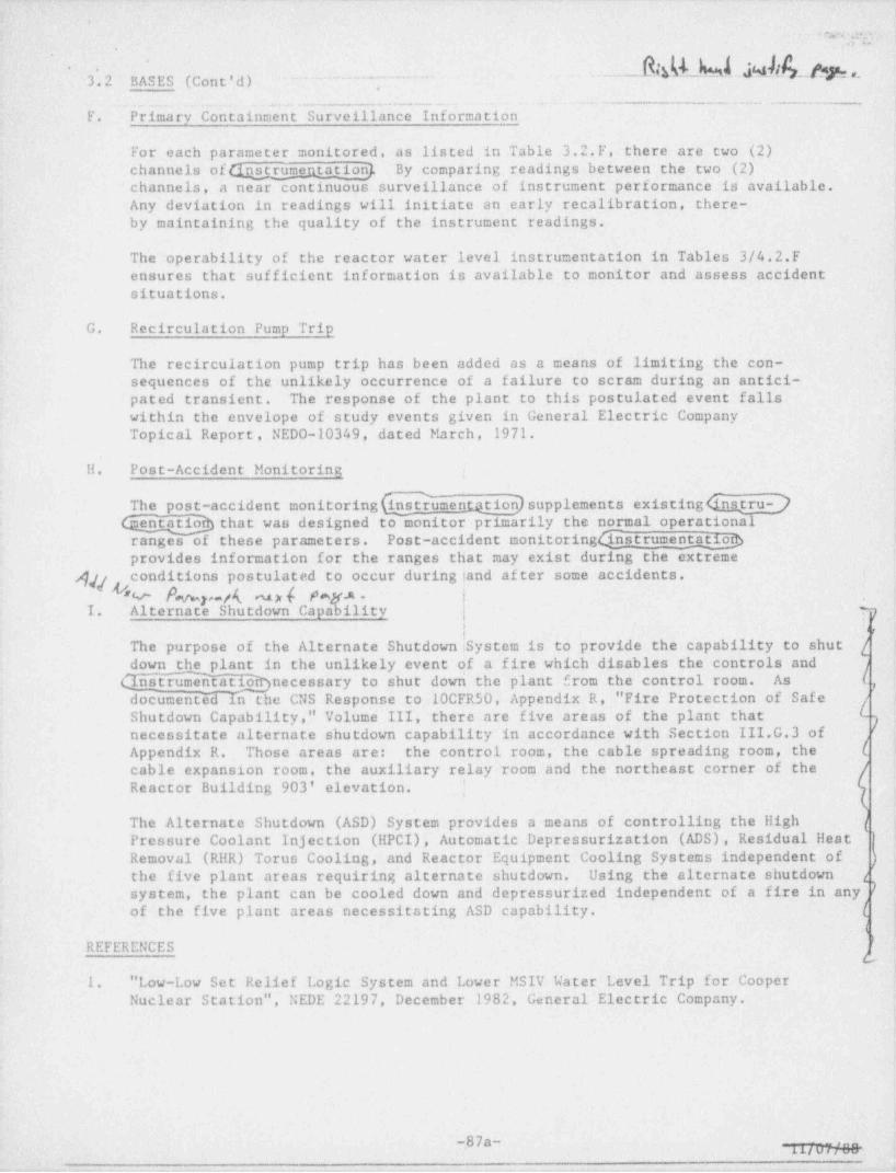
F. Primary-Containment Surveillance Information..
For each parameter monitored, as listed in Table 3.2.F. there are two (2)channels of Qnstrumentation} By comparing; readings between the two (2)channels, a near continuous surveillance of . instrument performance is available.. ;
Any deviation in readings will initiate an early recalibration, . there- i
by. maintaining the quality of the instrument readings.
'The operability of the reactor water level instrumentation in Tables 3/4.2.Fensures that' sufficient information is available to monitor'and assess accident- :jsituations.
G. -Recirculation Pump Tripj
The recirculation pump trip has been.added as a means of limiting the con-sequences of-the unlikely occurrence of a failure to scram during an-antici-- ,
pated transient. The response of.the plant to this postulated event' falls-within the envelope of study events given in General Electric CompanyTopical Report..NEDO-10349, dated. March, 1971. ;
H. Post-Accident Monitoring i
The post-accident monitoring h umentation] supplements existing dnatru- )that was designed to monitor primarily the normal operational. t
ranges of these parameters. Post-accident monitoringCins_trumentatiog ,
~
'provides information for the ranges that may exist dur1ng the extremeconditions postulated'to occur during jand af ter some accidents.g U" Y
*
k y g m [ P s y.n .*
,
1. Alternate' Shutdown Capability pj v
The purpose of the Alternate Shutdown System is to provide the. capability'to. shut i
down the plant in the unlikely event of a fire which disables the' controis and jC1nstrumentatioirynecessary'to shut down the plant from the' control room.- As .. ( g,documentiid in the CNS Response co .10CFR50, Appendix R,f " Fire Protection' of. Safe , r .
Shutdown Capability," Volume III, there are five- areas of the plant that- _ p'necessitate altcrnate shutdown capability in accordance with Section III.G.3 ofAppendix R. Those areas'are: the control room, the cable' spreading room, the' :[ ;
cable expansion room, the auxiliary relay room and the northeast corner of the-Reactor. Building 903' elevation.. |
The Alternate Shutdown (ASD) System provides a means of controlling'the High ]Pressure Coolant Injection (HPCI), Automatic Depressurization' (ADS), Residual Heat - |',+
Removal (RHR) Torus Cooling, and _ Reactor Equipment Cooling Systems ' independent of ? ),the five plant areas requiring alternate shutdown. ..Using'the alternate shutdown" z
; +
system, the plant can be cooled down and depressurized' independent ofJa fire in'any. L|~
,of the five plant areas necessitating ASD capability. h ;
l i
REFERENCES 'C'Ib~;
1. " Low-Low Set Relief Logic System and Lower MSIV Water Level Trip for CooperNuclear Station", NEDE 22197, December 1982, General Electric Company. >
c!
t
*
.87a-- - _. , ,

. . . , -- . . .. .. - .. .
.
.
r
New Paragraph for BASES, 3.2.H-_
The' Primary Containment ' Hydrogen / Oxygen Concentration--'Analyzers are utilized to monitor primary containment hydrogen
and oxygen concentrations during both normal plant operations.and post-accident. By . allowing the utilization of this.-
'
INSTRUMENTATION 'o n an intermittent -basis during normaloperations, the applicable surveillance requirements .for'
checking hydrogen and oxygen 'are satisfied while ensuring theavailability of the INSTRUMENTATION for continuous monitoring . [[.,.
post-accident. Intermittent sampling 'of hydrogen i
Ij concentrations during normal plant operations is permitted by! NUREG-0737, Item II.F.1.6. ,
t_
_ mt
b
,
.
,
4
I
|
d.1
|
|
- 1
, s

-----
e
RIM h4d hl /.GAi ~ f(,,,,
, - .
LIMITING CONDITIONS FOR OPERATION. SURVEILLANCE REQUIREMENTS
4.7 A.4 (cont'd.) - p--3.7.A.4 (cont'd.)
.c. The total leakage between the dry- -
"U "E cyc h each vacuum"" "C" *--
breaker valve shall-be visually'in-well and suppression chamber shall j
be less than the equivalent leakage 4 SPected to insure proper maintenance# nd. operation of the position indication
through a l di, eter orffice.switch. The differential pressure set-cpoint shall be verified. .
d. Priortoleactorstartup)aftereachd. Ifspecifications3.7.A.4.a.b,>rcgrefueling, a leak test of the drywell.
cannot be met, the situation siallt Suppression chamber structure
be corrected within 24 hours or the shall be conducted to demonstratereactor will be placed in a e 1d
that the requirement of 3.7.A.4.cCyghqtdowri conditio37within the sub- is met.seqiient 24 hours.
M ()C. 5. Oxygen Concentration
5. . Oxygen concentration
a. The p " r m e h r oxygen con-'
- a. After completion of the startup test centration shall be measured andE)K.Tc A program and demonstration of plant
Ar~~N recorded at least twice weekly.V fD EL- electrical output, the p ._, s m.
.
.FW@ ntmosphere shall be reduced gg gg-
-*- - - - '=*to less than_4% oxygen with nitrogen -
dh)Wfb . N'"##"ring 6eactor power opera on
with .:::: : -'--[- -.: above sspyr.ustw Cksome k .'-' == ^ 1 ^-100 psig, except as specificd in
3.7.A.5.b. Ap cy,
b. The quantity of' liquid nitrogen inb. Within the 24-hour period subsequentthe liquid' nitrogen storage tank shall
to placing the reactor in the Run ode. be determined twico per week when thefollowing aghutdowi), the cc.tc;r ;.c.-tl v lume requirements of 3.7.A.S.c areatmosphere oxygen Eoncentration shall
f g ($ be reduced to less than 4% by volume in effect.
and maintained in this condition.
L De-inerting ym,mence 24 hours-_
prior to aTahutdown)
| c. When the i.tn.,-..; atmosphere oxygen
| concentration is required to be lessthan 4%, the minimum quantity of. liquidnitrogen in the liquid nitrogen storagetank shall be 500 gallons.
d. If +h+--specifications - J 3.7. A.5.a.
c cannot be met, an orderly shutdown gshall be initiated and the reactor
shall be in a6Bd shutdown condition)within.24 hours.
Me'm_ _ ,,, , ,
x . --_m s.,.m.s.m . ..
are a plicabic dur m- - ' hv r.;
! dontinuous ietween the dates of. . :, ' ^ 2 n / . ;w a , u u .. .
.) s . _ _ /27/22'
- - _ - _ - . . . .164 ~. -- - - --- .
o_ _ _ _ _ _ _ _ _ _ _ _ _ _ _ _ _ _ _ _ _ _ _ _ _ _ _ _ _ . _ _ _ _ _ _ _ -- _l

_-- - - __
c3 or ca de h ..
e _
M b3.7.A & 4.7.A BASES (ce it' d)
bhprimarycontainment is normally slightly pressurized during periods of actor
hPOWE( operatiod Nitrogen used for inerting could leak out of the containment but air~
could not leak in to increase oxygen concentration. 1.. da : ntri=:nt i; fill:d
W .ng:- :: S: wi :? _ . u m . .n i . . -d;d -r- rm M--
'" - - - - least twice _ a weekJ-tMoxygen concentration v111 tmy o% gen eow.ledh mi.14,ug luirm.Med,
.
-- -
determined 2: MN := :. p,M@ gua ,ee M . ,, "Th 3. 2. H -__ /
The 500 gallon conservative lim t on tne nicrogen stora5e cans assures tnac- acequatetime is available to get the tank refilled assuming normal plant operation. Theestimated maximum makeup rate is 1500 SCFD which would require about 160 gallons fora 10 day makeup requirement. The normal leak rate should be about 200 SCFD.
3.7.A.6 & 4.7.A.6 LOW-LOW SET RELIEF FUNCTION
The low-low set relief logic is an automatic safety relief valve (SRV) control systemdesigned to mitigate the postulated thrust load concern of subsequent actuations of
during certain transients (such as inadvertent MSIV closure) and small andn
in ermediate break loss of-coolant accident (LOCA) events. The setpoints used inSection 3.7.A.6.b are based upon a minimum blowdown range to provide adequate timebetween valve actuations to allow the SRV discharge line high water leg to clear,
__::= ; 1.- ,coupled with consideration of instrument inaccuracy and the C.wab e isolation setpoint.
The as-found setpoint for NBI-PS-51A, the pressure switch controlling the opening ofRV-71D, must be 6 1040 psig. The as-found closing setpoint for NBI-PS-51B must beat least 90 psig less than 51A, and must be 2 850 psig. The as-found setpoint for
NBI-PS-51C, pressure switch controlling the opening of RV-71F must be s 1050 psig.The as-found closing setpoint for NBI-PS-51D must be at least 90 psig below Sic, andmust be 2 850 psig. This ensures that the analytical upper limit for the openingsetpoint (1050 psig), the analytical lower limit on the closing setpoint (850 psig)and the analytical limit on the blowdown range (2 90 psig) for the Low Low Set Relief 'Function are not exceeded. Although the specified instrument setpoint tolerance 'isi 20 psig, an instrument drift of i 25 psig was used in the analysis to ensure
set oints. .The opening-adequate margin in determining the valve opening and closinnetpoint is set such that, if both the lowest set non-LLS and the hi est'sec '
the LLS R- willof the two LLS @ drif t 25 psig in the worst case direct ons,still control suose Likewise, the closing setpoint is set toensure the LLS @ quent @ actuations. closing setpoint remains above the MSIV low pressure trip. The90 psig blowdown provides adequate energy Aase from the vessel to ensure time for-r
the water leg to clear between subsequent (S/RV)actuations.3.7.B & 3.7.C STANDBY GAS TREATMENT SYSTEM AND SECONDARY CONTAINMENTfpowC_QAu cy, y
v The secondary containment is desi ned to minimize any/fround level release of
k[ building provides Caicondary containmentadioactive ciate rials which migncve it from _a sergus accident. The reactor
uring(reactor'bveratTonlwhen the drywell is,sealed and in service. The reactor building provides(primary containmentlvhen the
_ reactor _ ir/Thutvdown]and the drywell is open, as during refueling.~ Because the-]sellO#U secondary 'containmeTnt is an integral part of the complete containment s ys tem ,-
Qg_nniury conta2nmentJis required at all times thacGirimary containment]is requiredas durin5 and during movement of Ioads which could potentially 7
irradiated /[hfSlinG'.46 s well
uel in the secondary containment. Gecondary containment?may 'e._u opu c s damageroken for short periods of time to allow access to the reactor _ building roof to
[performnecessaryinspectionsandmaintenance. / 7M E G E 7P1 4ficAf,--
s 3Rggemio| The Standby cas Treatment System consists of two, distinct subsystems, each
W6E containing one exhaust fan and associated filter train, which is designed 'to filterand-exhaust the reactor building atmosphere to the stack during secondary containmentisolation conditions. Both Standby Gas Treatment System fans are designed to |automatically start upon containment isolation nd to maintain the reactor- buildingpressure to the design 4gative pressure so t t all leakage should be in leakage.Should one subsystem f 1 to start, the redun nt subsystem is designed to start |putnmntically. Each o the two fans has 100 pe ent capacity.
Se*f N [alg ral)-180-
~ 3/11/02-l
- - - -,J

, ,, s >n . a -. .. ;-..p.. e .* < u ,,u, ,.- a ,,,:n..>.., ..a. , >> aw , .s
.
.'.g .-
I , g- "' #9 ??@ gips . step ew ra p ) >5g e 4m
., - _ __ , ,,.
. ..'
~ ' '
t* * p u we e.' ,.,
.
%''i Iy..
''f C;i ;' ':if ti f .ti
(f pf, N WO fhN #h{pan e, \ so 4, k M -
: ,
.
$
s
.3-
.
t
r
.-
gM
'/ / / V. A'
,
.
,
1
|,
' -
j.
4
i':
~ !
,
- i
'
.-7 : .. Iwavu/m e'2' (. 'rylOite '. . - - . _ . . 1
--. 1P
' '_, - . - v,c , , , ,%. .

,
'j (''| .* '
Attachment to*
'
NSD940428
APPENDIX C - REVISED AFFECTED TEC11NICAL SPECIFICATION PAGES
|
|
|
j
i
_ __ _ _ _ _ . _ _ _ _ _ _ _ . _

. + v .
_
-
COOPER NUCLEAR STATION -
TABLE 3.2.F .
PRIMARY CONTAINMENT SURVEILIANCE INSTRUMENTATION *J_
Minimum Number Action Required 'of OPERABLE When Minimum
Instrument INSTRUMENT ConditionInstrument I.D. No. Rante CHANNELS Not Satisfied (1) ,
Reactor Water Level- NBI-LI-85A -150 to +60 inches 2 A,B,C1:01-LI-85B -150 to +60 inches ,
Reactor Pressure RFC-PI-90A 0 to 1200 psig 2 A,B,CRFC-Pi-90B 0 to 1200 psig
,
Drywell Pressure PC-PR-2A -5 to 70 psig 2 A,B,CPC-PR-2B -5 to 70 psigPC-PR-1A 0 to 250 psig 2 FPC-PR-1B 0 to 250 psig
2
Drywell Temperature PC-TR-503 50 to 170*F 2 A,B,CPC-TI-505 A,B,C,D,E 50 to 350*F
* Suppression Chamber / Torus PC-TR-21A 0 to 300*F 2 A,B,C.--
T Air Temperature PC-TR-23, Det 1&2 0 to 400*F
Suppression Chamber / Torus PC-TR-24, Det la to lh 0 to 250*F 1 (2) Note 2Water Temperature . PC-TR-25, Det 2a to 2h 0-to 250*F,
Suppression Chamber / TorusWater Level PC-LI-10 -4 to +6 feet 2 A,B,C
PC-LR-ll .-4 to +6 feeta PC-LI-12 -10 to +10 inches 2 A,B,C,E
PC-LI-13 -10 to +10 inchesy PC-LR-1A 0 to 30 feet. .2 F
PC-IR- 1B 0 to 30 feet
f Suppression Chamber / Torus' PC-PR-20 0.to 2 psig 1 B,CPressure
Control-Rod Position- N.A. Indicating Lights 1 A,B,C,D
!i' Neutron Monitoring. N.A. S.R.M., I.R.M., .1 A,B,C,D~
LPRM0 to 100% power
iNotes: * Other' Primary Containment Surveillance Instrumentation is located in Table 3.2,H-Primary Containment_
Hydrogen /0xygen-Analyzer<
w < tn - Y ~ v w w + | w. - e a :n. w . m - - - - - - - . ----------A----.--- I--

. . -.. -- . . .m. _ _ . . . = _ __ -. _ _ _ ..___4 _
,
.2
,'
,
NOTES FOR TABLE 3,2.F
minimumnumberofOPERABLEINSTRUMENT[1. The following - actions will be taken if theCHANNELS as required are not available. . _ .
A. From and after the ~date that one of these parameters is reduced *
to - one . |indication, continued REACTOR POWER OPERATION is permissible during the,
succeeding thirty days unless such INSTRUMENTATION is sooner made OPERABLE. . | -- ,
B. From and after the date that one of these parameters is not indicated in thecontrol room, continued REACTOR ' POWER OPERATION is permissible during - the .' !succeeding seven days unless such INSTRUMENTATION is. sooner made OPERABLE. |-
C. If the requirements of A and B above cannot be me t ,- an orderly f SHUTDOWN |'shall be initiated within 24 hours.
D. These surveillance' instruments are considered to be redundant to each other.
E. In the event that both channels are inoperable and indication cannot = berestored in six (6) hours, an orderly SLUTDOWN ~ shall' be initiated .' and the j.reactor shall~be in HOT SHUTDOWN in six (6) hours and in a COLD SHUTDOWN; [
'
condition in the following eighteen (18) hours. 7
F. From and after the date that one of these parameters is reduced. to one..
|indication, either - restore the inoperable component (s) to OPERABLE statuswithin 30 days of the event, or prepare and submit a Special Report ; to ' the --
Commission outlining the action taken, the cause of - the .noper bility and,
the plans and schedule for restoring the system to OPERABLE'_ status. ' In the |- >
event that both channels are inoperable and indication cannot be-restored infourteen (14) days, an orderly SHUTDOWN shall be' initiated.- |-
2. Each channel contains eight detectors. A channel-is considered' inoperable if two:adj acent detectors. are unmonitored by the channel in question.
A. From- and after the date that one channel becomes inoperable, . continued --
REACTOR POWER OPERATION is permissible during the succeeding seven idays -|,
unless sooner made OPERABLE.
B. From and after the date that the second channel becomes inoperable, an- ;
orderly SHUTDOWN shall be initiated within ' 48 hours unless : sooner made-|-OPERABLE. g'
<
l
'
7;'
'
.,
,
I
,
-66- -
,i
I..,: . _ _ : .- r; u; <- ~ : - -%+-

.. , . _ ,
k
- -
-
..
t i-1 COOPER NUCLEAR STATION^
9'c
*TABLE 3.2.H ]POST-ACCIDENT MONITORING INSTRUMENTATION REQUIREMENTS * -
,
Minimum Number of Action Required When- ._Instrument OPERABLE INSTRUMENT Component OPERABILITY- |.
Instrument -ID Number Rance CHANNELS Is Not Assured |'
Elevated Release Point-(ERP). RMP-RM-3B 1.00E-2 to 1 (Note 1) -AMonitor (High Range Noble 1.00E+5 pc/cc
Gas)- (Xe-133Equivalent)
Turbine Building Ventilation RMV-RM-20B 1.00E-2 to 1 (Note 1) .AExhaust Monitor 1.00E+5 g/cc
..
(High Range No.319 Cas). (Xe-133 A
. Equivalent)
Radwaste/ Augmented Radwaste RMV-BM-30B 1.00E-2 to 1 (Note 1) AExhaust Monitor 1.00E+5 pc/cc..
$ (High Range NobleLGas) (Xe-133? Equivalent)
Primary Containment Gross RMA-RM-40A 1.0-1,0E+7 R/Hr. 2 (Note 1) ARadiation Monitor RMA-RM-40B 1.0-1.0E+7 R/Hr.
-Hydronen 'Oxycen
J. ' Primary Containment < - PC- AN -H /0 1 0% to 30% 0 to 10% 2 (Notes 1, 2, and 3) B2 2
-) . Hydrogen /0xygenConcentration Analy=er PC- AN-H /0 II - 0% to 30% 0 to 30%'
2 2
Notes: ~*. Other Post-Accident Monitoring Instrumentation is located in Table 3.2.F- -| -'Drywell-Pressure, PC-PR-1A and lB, Suppression Chamber / Torus Water Level PC-LR-1A and.13
;:-
!
L_
t _-__w. . _ - _ _ -

- _ . _ _ - - _ . _ . _.. .. _ _
|.
q,.
,
'
, .
; NOTES FOR' TABLE ~3.2.H -
'j' Action:
A. With the number of OPERABLE compdt$ent a less - than required by the . minimum |-component OPERABLE cequirements, initiate the preplanned' alternate method. of. | l-
monitoring the appropriate parameter (s) within 72 hours, and: '
1) Either restore the inoperable component (s) to OPERABLE status within1j. >
7 days of the event, or
,
2) Prepare and submit a Special Report to the Commission within 14'. daysfollowing the event outlining the action taken, the cause .' of theinoperability and the plans and schedule for restoring. the system toOPERABLE status. .|.
'
'!-,
B. The following actions will be taken' if the minimum number of OPERABLEINSTRUMENT CHANNELS as required are not OPERABLE: !
1) With the number of OPERABLE channels one less than the minimum number !-of OPERABLE channels shown, restore the inoperable channel to OPERABLE I
'
Istatus within 30 days or be in at least HOTSHUTDOWNwithinthenext~[12 hours.
'
3
2) With no OPERABLE channels available, restore at least one channel to- |~
,
OPERABLE status within 7 days or be in at least ' HOT SHUTDOWN within - |-the next 12 hours.
'|Notes:
1. These instruments are required to be OPERABIE ~ at all times except when.the 'l1reactor is in COLD SHUTDOWN or in the REFUEL mode during a~ REFUELING OUTAGE, :|
2. With two channels OPERABLE, the normal condition may include ' samplingintermittently.
3. During periods when both oxygen analyzer ' channels are_ inoperable,. grab-[samples may be taken to verify primary containment oxygen concentration. :
q
;
+ 2
W
'I4
,
-67b-I
'
m m .:q n . a - - J( , . p .,;.,....,_

_.,
_
.
COOPER NUCLEAR STATION -
TABLE 4.2.F -
PRIMARY CONTAINMENT SURVEILLANCE INSTRUMENTATION *'=f . ".
TEST AND CALIBRATION FREQUENCIES.
Instrume-Instrument I.D. No. Calibration Frequency Instrument Check
Reactor Water Level NBI-LI-85A .Once/6 Months Each Shift '
NBI-LI-85B Once/6 Months Eacit Shift
Reactor Pressure RFC-PI-90A Once/6 Months Each ShiftRFC-PI-90B Once/6 Months Each Shift
Drywell Pressure PC-PR-2A Once/6 Months Each ShiftPC-PR-2B Once/6 Months Each ShiftPC-PR-1A Once/6 Months Each ShiftPC-PR-1B Once/6 Months Each Shift
,
Drywell Temperature PC-TR-503 Once/6 Months Each Shift.PC-TI-505 A,B,C,D,E Once/6 Months Each Shift |'
$
- 'h Suppression Chamber / Torus PC-TR-21A Once/6 Months Each ShiftAir Temperature PC-TR-23, Det 1 & 2 Once/6 Months Each Shift*
,
'
' Suppression Chamber / Torus PC-TR-24, Det la to lh once/6 Months Each Shift,
Vater Temperature PC-TR-25, Det 2a to 2h Once/6 Months Each Shift
Suppression Chamber / Torus 'PC-LI-10 Once/6 Months Each Shift4
i Water Level PC-LR-ll Once/6 Months Each Shift :
L PC-LI-12 Once/6 Months Each Shift '
PC-LI-13 Once/6 Months Each ShiftPC-LR-1A Once/6 Months Each Shift
g
L PC-LR-1B Once/6 Months Each Shift
!!] Suppression Chamber / Torus PC-PR-20 Once/6 Months Each Shift
|i Pressure
b .
J Control Rod Position N.A. N.A. Each Shift!: Neutron Monitoring (APRM) N.A. Once/ Week Each Shift-
[ l-@L ' Notes: *- Other Primary Containment Surveill'nce' Instrumentation calibration-requirements'are in.a
= Table 4.2.H A Primary.. Containment Hydrogen / Oxygen Concentration-Analyzer.
F!
L.- _ - - - ----- -. . . . . - . - . . . . -.. - . - . -

_
..
. _
COOPER NUCLEAR STATION'
TABLE 4.2,H-*
CALIBRATION FREQUENCY FOR POST-ACCIDENT MONITORING INSTRUMENTATION *.
Instrument Function CalibrationInstrument ID Number Test Frecuency Frecuency
Elevated Release Point (ERP)Mcnitor (High Range Noble RMP-RM-3B once/ Month once/ CycleGas)
Turbine Building Ventilation RMV-RM-20B Once/ Month once/ CycleExhaust Monitor-
:! .(High Range' Noble Cas)
Radwaste/ Augmented Radwaste RMV-RM-30B Once/ Month once/ CycleExhaust Monitor-
{ (High Range Noble Gas)
Primary Containment Cross RMA-RM-40A Once/ Month Once/ Cycle
. 4 Radiation Monitors ** RMA-RM-40B Once/ Month once/ Cycle
Y4
Primary Containment PC-AN-H /0 I Once/ Month once/ Quarter- 2 2Hydrogen / Oxygen PC-AN-H /0 II Once/ Month once/ Quarter2 2
. Concentration Analyzer ***
75.'
'
Notes: * Other Post-Accident' Monitoring Instrumentation calibration. requirements are in Table 4.2.F-DrywellPressure. PC-PR-1A and 1B, Suppression Chamber / Torus Water Level PC-LR-1A and IB.
** C11ANNEL CALIBRATION shall consist of an electronic . calibration of the . channel, not including thedetector, for range. decades above 10 R/hr and a one point calibration check of the detector below.'10 R/hr.with an installed.or portable gamma. source.
*** Instrument check required once/ day.for the oxygen portion of the inservice analyzer.y-s;-
.
, , , , . - . -. e... . .4- , , . ., - . . . . < . . . . - - . .
. ,.- - ~ . . . ... . --- ~ . . ..
.
'.
..^'
. . . .
t
3.2 PASES (Cont'd)
F. Primary Containment Surveillance Information
For each parameter monitored, as listed'in Table 3.2.F. there are two (2) channelsof INSTRUMENTATION. By comparing readings oetween: the two - (2) 4hannels , a near 'l -continuous surveillance of instrument performance is available.. Any deviation inreadings will initiate an early recalibration, thereby maintaining the quality'ofLthe instrument readings.
The operability of the reactor water level INSTRUMENTATION in Tables 3/4. 2.F ' l 'ensures that sufficient information is available ' to monitor and assess = accident .
situations.
G. Recirculation Pumn Trin
^
The recirculation pump trip has been added as a means of limiting the consequences.of the unlikely occurrence of a failure to scram during an anticipated' transient.The response of the plant to this postulated event falls within the envelope.ofstudy events given in General Electric Company Topical Report, 'NEDO-10349, datedMarch, 1971. -
H. Post-Accident Monitoriny,
The post-accident monitoring INSTRUMENTATION supplements existing INSTRUMENTATION- |'that was designed to monitor primarily the normal operational ranges of . theseparameters. Post-accident monitoring INSTRUMENTATION provides information for the . | i;
ranges that may exist during the extreme conditions postulated to occur during.and- ,
after some accidents. - r
.
The Primary containment Hydrogen /0xygen Concentration Analyzers are utilized tomonitor primary containment hydrogen and oxygen concentrations during both normalplant operations and post accident. By allowing the utilization .of thisINSTRUMENTATION on an intermittent basis during normal operations, the-applicable- '
survaillance requirements for checking hydrogen and oxygen are satisfied , while ;ensuring the availability of. the INSTRUMENTATION for continuous monitoringpost-accident. Intermittent sampling of hydrogen concentrations. during . n'ormal:
,
:'pl.mt operations is permitted by NUREG-0737 Item II .F.1.6.
1 $lternate Shutdown Canability .
The pu pose of the Alternate Shutdown System is to provide .the capability to ' shutdown the plant in.the unlikely event of a' fire which disables the. controls) andINSTRUMENTATION - necessary to shut. down the plant from the e control ' room. As |documented in the CNS Response to 10CFR50, Appendix R ," Fire Protection of SafeShutdown Capability,"' Volume III, there are five areas - of. the plant that ,
necessitate alternate shutdown capability in accordance with ' Section III.G.3 ofAppendix R. Those areas -are: .the control room, the cable spreading room, . thecable expansion room, the auxiliary relay room and 'the - northeast corner of the- it
Reactor Building'903' elevation.
of controlling the HighThe Alternate Shutdown (ASD) System - provides a means *
Pressure Coolant Injection (HPCI), Automatic Depressurization (ADS) . Residual Heat :Removal (RHR) Torus Cooling, and Reactor Equipment Cooling Systems independent ofthe five plant . areas requiring alternate shutdown. Using the alternate shutdownsystem, the plant can be cooled down and depressurized independent 'of a fire ;inany of the five plant areas necessitating ASD capability. ;
REFERENCES ,
.- l
1. " Low-~ Low Set Relief Logic System and Lower MSIV Water Level Trip for - Cooper 'jNuclear Station", NEDE 22197,. December 1982, General Electric Company. l
1
-87a- 1<
J'J L --, .AA. J-,%

.
9
*.
LTMTTTMC rnNDTTinNS FnR OPFRATinN CUPVFTT.TANrF PFnnTPFMENTS
3,7.A 4 (cont'd.) 4.7 A.4 (cont'd.)
c. The total leakage between the c. Once each OPERATINC- CYCLE, each |drywell and suppression chamber vacuum breaker valve shall beshall be less than the equivalent visually inspected to insure
| 1eakage through a 1 inch diameter proper maintenance and operationorifice. of the position indication switch.'
The differential pressure setpointshall be verified.
d. If specifications 3.7.A.4.a, b, or d. Prior to REACTOR STARTUP after.|c cannot be met, the situation each refueling, a leak test.of theshall be corrected within 24 hours drywell to suppression chamberor the reactor will be placed in a structure shall be conducted to
| COLD SHUTDOWN CONDITION within the demonstrate that the requirementsubsequent 24 hours. of 3.7.A.4.c is met.
S. Oxymn Concentration 5. Oxyren Concentration
a. After completion of the startup a. The drywell and pressuretest program and demonstration of suppression chamber. oxygenplant electrical output, the concentration shall- be measureddrywell and pressure suppression and recorded at least twice
|weekly.chamber atmosphere shall be
reduced to less than 4% oxygen ,with nitrogen gas during REACTORPOWER OPERATION with REACTORVESSEL PRESSURE above 100 psig,except as specified in 3.7.A.S.b.
b. Within the 24-hour period b. The quantity of liquid nitrogen insubsequent to placing the reactor the liquid nitrogen storage tank
a shall be determined twice per weekin the RUN mode followingSHUTDOWN, the drywell and pressure when the volume requirements ofsuppression chamber atmosphere 3.7.A.5.c are in effect.oxygen concentration shall bereduced to less than 4% by volumeand maintained in this condition.De-inerting may commence 24 hours
| prior to a SHUTDOWN.c. When the drywell and pressure
suppression chamber atmosphereoxygen. concentration is requiredto be less than 4%, the minimumquantity of liquid nitrogen in theliquid nitrogen storage tank shallbe 500 gallons,
d, _f specifications 3.7.A.S.a, b, orc cannot be met, an orderlySHUTDOWN shall be initiated andthe reactor shall be in a COLDSHUTDOWN CONDITION within24 hours.
-164-
> - . . - . __x. a_

. - _--
.
1, ..;
'
,
,
3.7.A & 4.7.A BASES (cont'd) ,
-The primary containment is normally slightly pressurized during periods of REACTORPOWER OPERATION. Nitrogen used for inerting could leak out of the containment but ,
air could not leak in to -increase oxygen concentration. Primary containmentoxygen concentration will'be determined at least twice a week. Specifications foroxygen concentration monitoring instrumentation are located -in Table 3.2.11.
*
The 500 gallon conservative limit on the nitrogen storage tank assures thatadequate time is available to get the tank refilled assuming normalE plantoperation. The estimated maximum makeup rate' is 1500 SCFD which would requireabout 160 gallons for a 10 day makeup requirement. 'The normal leak rate should beabout 200 SCFD
3.7.A.6 & 4.7 A.6 LOW-LOW SET RELIEF FUNCTION
The low-low set relief logic is an automatic safety relief valve . (SRV) control.system designed to mitigate the postulated thrust load concern of L subsequent
The-|-actuations of SRVs during certain transients (such as inadvertent MSIV clorure)'
.
and small and intermediate break loss-of-coolant accident (LOCA) events.setpoints used in Section 3.7. A.6.b are based upon a minimum blowdown range toprovide adequate time between valve actuations to allow the SRV discharge line ihigh water leg to clear, coupled with consideration of instrument inaccuracy and -
,
the MSIV isolation setpoint. ||The as-found setpoint for NBI-PS-51A, the pressure switch controlling the openingof RV-71D, must be s 1040 psig. The as-found closing setpoint for NBI-PS-51B mustbe at least 90 psig less than 51A, and must be 2 850 psig. The as-found setpointfor NBI-PS-51C, pressure switch controlling the opening of .RV-71F must. be5 1050 psig. The as-found closing setpoint for NBI-PS 51D must be at: least
'
90 psig below Slc, and must be 2 850 psig. This ensures that the analytical upper-'
limit for the opening setpoint (1050 psig), the analytical . lower limit on theclosing setpoint (850 psig) and the analytical limit on the~ blowdown range _ (290 psig) for the Low-Low Set Relief Function are not exceeded. Although - thespecified instrument setpoint tolerance is i 20 psig, an instrument drift of.i.25 psig was used in the analysis to ensure adequate margin in determining thevalve opening and closing setpoints. The- opening setpoint is set such that, if '
*
both the lowest set non-LLS SRV and the highest set of . the two LLS SRVs drift.25 psig in the worst case directions, the LLS SRVs will still control subsequentSRV actuations. Likewise, the closing setpoint is set to ensure the LLS: SRVclosing setpoint remains above the MSIV low pressure trip. The 90 psig blowdownprovides-adequate energy release from the vessel to ensure time for the water' legto clear between subsequent SRV actuations. |
.
e
.
u!
|
i
-180-1
_ , ~ 9. . - f . . . . . -4. . _

,
*.
.
3.7.B 6 3.7.C STANDBY CAS TREATMENT SYSTEM AND SECONDARY CONTAINME3T
The secondary containment is designed to minimize any ground level release ofradioactive materials which might result from a serious accident. The reactorbuilding provides SECONDARY CONTAINMENT INTEGRITY during REACTOR POWER OPERATION 1
when the drywell is-sealed and in service. The reactor building provides PRIMARY ICONTAINMENT INTEGRITY when the reactor is SHUTDOWN and _ the drywell is open, as - !
during a REFUELING OUTAGE. Because the secondary containment is an integral partof the complete containment system, SECONDARY CONTAINMENT INTEGRITY is required atall times that PRIMARY CONTAINMENT INTEGRITY is required as well as duringrefueling, and during movement of loads which could potentially damage irradiated-fuel in the secondary containment. SECONDARY CONTAINMENT INTEGRITY may be broken | ,
'for short periods of time to allow access to the reactor building roof to performnecessary inspections and maintenance.
,
The Standby Gas Treatment System consists of two, distinct subsystems, eachcontaining one exhaust fan and associated filter train, which is designed to-filter and exhaust the reactor building atmosphere to the stack during secondarycontainment isolation conditions. Both Standby Gas Treatment System fans aredesigned to automatically start upon a Group 6 containment isolation signal and to |maintain the reactor building pressure to the design negative pressure so that all.leakage should be in-leakage. Should one subsystem fail to start, the redundantsubsystem is designed to start automatically. Each of the two fans has
'100 percent capacity.
,
!1
4
ii
s
?
1
i
..
i.
-181- |
, .
- n-- _ _. _ , - - -, i