appendix b part 5 special provisions for ...eng2.lacity.org/techdocs/sewer-ma/appx-b.pdfappendix b...
TRANSCRIPT

APPENDIX B
PART 5
SPECIAL PROVISIONS FOR SEWER REHABILITATION
SECTION 500 - PIPELINE SYSTEM REHABILITATION
SECTION 500-1 - PIPELINE REHABILITATION
500 -1.1 Requirements -1.1.1 General -1.1.2 Submittals -1.1.3 Preliminary Inspection -1.1.4 Television Inspection -1.1.5 Miscellaneous -1.1.6 Rejection -1.1.7 Measurement and Payment
500 -1.2 Pipeline Point Repair -1.2.1 General -1.2.2 Materials -1.2.3 Excavation -1.2.4 Sewer Bypassing and Dewatering -1.2.5 Notification of Work -1.2.6 Installation and Field Inspection
500 -1.3 High Density Polyethylene Liner Pipe (fused joint) -1.3.1 General -1.3.2 Material Composition -1.3.3 Liner Pipe Acceptance -1.3.4 Marking -1.3.5 Chemical Resistance and Physical Testing -1.3.6 Installation and Field Inspection -1.3.7 Grouting Annular Space -1.3.8 Service Connections
500 -1.4 Cured-in-Place Liner Pipe-1.4.1 General-1.4.2 Material Composition and Testing
-1.4.3 Tube Acceptance -1.4.4 Chemical Resistance -1.4.5 Resin-Impregnated Tube Installation Procedure -1.4.6 Installation -1.4.7 Curing -1.4.8 Service Connections

500 -1.5 PVC Sewer Lining System -1.5.1 General -1.5.2 Material Composition -1.5.3 Material and Equipment Acceptance -1.5.4 Marking -1.5.5 Chemical Resistance -1.5.6 Installation and Field Inspection -1.5.7 Grouting Annular Space -1.5.8 Service Connections
500 -1.6 Thermal Reduction Liner Process -1.6.1 General -1.6.2 Material Composition -1.6.3 Liner Pipe Acceptance -1.6.4 Marking -1.6.5 Chemical Resistance and Physical Testing -1.6.6 Installation and Field Inspection -1.6.7 Service Connections
500 -1.7 Deformed HDPE Sewer Rehabilitation System -1.7.1 General -1.7.2 Material Composition -1.7.3 Material and Equipment Acceptance -1.7.4 Marking -1.7.5 Chemical Resistance and Physical Testing -1.7.6 Installation and Field Inspection -1.7.7 End Seals -1.7.8 Service Connections
500 -1.8 Reinforced Plastic Mortar Liner Pipe -1.8.1 General -1.8.2 Material Composition -1.8.3 Liner Pipe Acceptance -1.8.4 Marking -1.8.5 Chemical Resistance and Physical Testing -1.8.6 Installation and Field Inspection -1.8.7 Grouting Annulus -1.8.8 Service Connections
500 -1.9 External Inplace Wrap (PVC) -1.9.1 General -1.9.2 Installer Qualifications -1.9.3 Preparation of Existing Pipe -1.9.4 Field Joining of Liner -1.9.5 Protection and Repair of Liner -1.9.6 Field Testing -1.9.7 Steel Reinforcement -1.9.8 Concreting Operations -1.9.9 Chemical Resistance and Physical Testing

500 -1.10 Folded PVC Sewer Rehabilitation System -1.10.1 General -1.10.2 Material Composition -1.10.3 Material and Equipment Acceptance -1.10.4 Marking -1.10.5 Chemical Resistance -1.10.6 Installation & Field Inspection -1.10.7 End Seals -1.10.8 Service Connections
SECTION 500-2 - MANHOLE AND STRUCTURE REHABILITATION
500 -2.1 Requirements -2.1.1 General -2.1.2 Manhole Steps -2.1.3 Safety -2.1.4 Removal and Disposal -2.1.5 Measurement and Safety
500 -2.2 Maintenance Hole Performing System -2.2.1 General -2.2.2 Concrete -2.2.3 Integral Locking PVC Liner -2.2.4 Chemical Resistance and Physical Testing -2.2.5 Installation and Field Inspection -2.2.6 Service Connections
500 -2.3 PVC Manhole and Wet Well Lining Systems -2.3.1 General -2.3.2 Materials -2.3.3 Chemical Resistance -2.3.4 Installation and Field Inspection -2.3.5 Service Connections
SPECIAL PROVISIONS FOR SEWER REHABILITATION
SECTION 500 - PIPELINE SYSTEM REHABILITATION
SECTION 500-1 - PIPELINE REHABILITATION
500-1.1 Requirements
500-1.1.1 General. This section covers the various pipeline system rehabilitation materials
and methods.
The type(s) of rehabilitation materials and methods for a given project shall be
designated on the Plans. The Agency may require testing of the materials and
methods for compliance with these requirements prior to delivery to the job site
and/or prior to acceptance depending upon the alternate selected. Materials shall
be not more than six months old from date of manufacture at the time of
installation. The intent of this Section is to provide various methods of pipeline
rehabilitation as an alternate to replacement.
The specifications herein do not address the structural capacity of the rehabilitation
systems described nor their structural requirements. All structural requirements as
they pertain to each specific installation shall be approved by the Engineer in
conformance with Subsection 2-5.3.
500-1.1.2 Submittals. All submittals required by these specifications but not limited to
grouting annulus pertinent to some rehabilitation methods shall meet the
requirements of the plans and Special Provisions.

500-1.1.3 Preliminary Inspection. The Contractor shall prior to the televising or
rehabilitation of the pipeline, clean the entire line and remove all obstructions.
500-1.1.4 Television Inspection. Closed Circuit Television Inspection (CCTV) shall be
required as both a pre and a post installation method to determine if the liner has
been installed as required and that all laterals have been reconnected properly.
Documentation consisting of a color video tape and written report detailing the
condition of the main line and lateral openings shall be submitted to the Engineer
for approval. If rejected, the Contractor shall be responsible for making all
necessary repairs until the requirements are met.
500-1.1.5 Miscellaneous. The Contractor shall be responsible for locating all service
connections and cleanouts. The Contractor shall provide notification of
work activities to all local users and provide interim sewer service as
necessary. Clean up and dust control shall meet the requirements of
Subsection 7-8.
Whenever service reconnection is needed, the invert of the service
connection shall match the bottom of the reinstated service opening. The
service opening shall be reinstated to 100% ± 5% of the original service
connection opening and the new edge shall be smooth and free of loose
material.
500-1.1.6 Rejection. If the Contractor uses any material other than an approved material or
an approved method, the Contractor shall, at its sole expense, remove the entire
rehabilitated pipe and replace it with a new pipe as directed by the Engineer. All
damaged rehabilitation materials shall be rejected and removed.
500-1.1.7 Measurement and Payment. Pipeline cleaning and inspection, including CCTV
inspection, shall be paid for

at the contract unit price in the bid for pipeline cleaning and all inspection including
CCTV. The unit price paid shall be considered full compensation for furnishing all
labor, material, tools, equipment, apparatus, and incidentals for doing all the work
required.
Pipeline point repair and rehabilitation shall be measured along the longitudinal
axis between the ends of the pipeline as shown on the plans and shall not include
the inside dimensions of structures.
The price per lineal foot or lump sum for point repair and rehabilitation shall be
considered full compensation for furnishing and installing all fittings, connections,
seals and special work shown on the plans, including all labor, materials and
equipment required; the removal of interfering portions of existing sewers, storm
drains and other improvements; the closing or removing of abandoned conduits
and structures; the excavation of the trench and/or access pits, if required; the
control of ground and surface waters; the preparation of subgrade; placing and
joining of pipe; backfilling the trench and/or access pit; temporary and/or
permanent resurfacing; and all other work necessary for point repair and
rehabilitation, complete in place.
Notes to Specifier (NTS) - referenced to pertinent Section paragraphs:
500-1.1 The reference to testing followed up by the inspectors to ensure that pre-fabricated
product are manufactured in accordance to the referenced Standards and these
Standards. The products and materials that are developed on site should be tested
in accordance to and meet the various strengths specified in these Standards.
500-1.2 Pipeline Point Repair

500-1.2.1 General. This section specifies point repair of existing sewers prior to
rehabilitation. The Contractor shall be responsible for repairing the sewer where
point repairs are identified on the plans or the special provisions. If this is not
shown, it will constitute extra work when approved by the Engineer.
The work shall include verifying the location of the spot repair through CCTV or
man-entry inspection of the sewer, locating all interfering utilities, furnishing all
labor and materials necessary for, but not limited to excavation, dewatering, pipe
repair or replacement, backfill, surface restoration, temporary flow bypassing,
sewer dewatering and traffic control.
500-1.2.2 Materials. The pipe and repair materials shall be the same as the existing line
unless otherwise indicated and shall comply with Section 207 for type and class
required.
500-1.2.3 Excavation. All trenching and excavation shall conform to Section 306.
500-1.2.4 Sewer Bypassing and Dewatering. When required by the Contract Documents or
the process, the Contractor shall bypass sewer flow around the work and dewater
the work area, all in conformance with Subsections 7-8.4 and 306-3.3.
500-1.2.5 Notification of Work. The Contractor shall notify the Engineer not less that 48
hours in advance of the planned time to begin point repair work at a particular
location.
500-1.2.6 Installation and Field Inspection. The installation of the replacement pipe and/or
repair work shall conform to requirements of Section 306. All point repairs shall
be

inspected and measured by the Engineer prior to any backfilling and compaction.
NTS - referenced to pertinent Section paragraphs:
500-1.2.2 The repair pipe should be of the same type removed for ease of connection, unless
prevailing reasons dictate otherwise.
500-1.2.3 The length of excavation is normally 5 to 10 feet beyond the pipe to be replaced.
This facilitates an easier closure.
500-1.2.4 Sewer Bypassing. The current "state of the art" on bypassing permit diverting
flows up to 100 million gallons per day, without any spillage.
Specific Operations. The Contractor should be encouraged to accomplish any
television or grouting work during the low flow periods of the day. This may still
require plugging the pipeline to the level of preventing upstream surcharging. The
sliplining utilizing jointed liner pipes normally will not cause upstream surcharging.
When the flows in the pipeline exceed one half the pipe diameter, the sliplining
operation becomes very difficult. The work is usually halted at that point,
therefore, upstream surcharging is generally not a problem. The use of solid wall
HDPE will usually require some bypassing unless the work is conducted during
low flow conditions.
Standby Equipment. The "Rain for Rent" bypass Contractor normally has one or
two standby gas operated pumps available for emergency use.
500-1.3 High Density Polyethylene Liner Pipe. (Solid Wall)
500-1.3.1 General. High Density Polyethylene Solid Wall liner pipe

for use in sanitary sewers, storm drains and house connection sewers, shall comply
with ASTM D-3350 or ASTM F-714. Unless otherwise indicated, liner for pipe
shall conform to SDR 32.5. Fittings shall comply with ASTM D-2683 or D-3261.
Fittings fabricated by mitered butt fusions are also permitted. The standard
dimensional ratios (SDR) shall conform to the following table:
Standard Allowable Feet *(Groundwater above invert)
Standard Dimensional Ratio(SDR)
Maximum for ungroutedinstallation
32.54.5
269.0
21 16.019 23.017
3015.5
44.0
* Safety factor not included
500-1.3.2 Material Composition. Pipe and fittings shall be made from HDPE resinscomplying with ASTM D-1248, Type III, Class C, Category 5, Grade P34, andASTM D-3350, and shall also meet the requirements of Subsection 207-19.2.
500-1.3.3 Liner Pipe Acceptance. Liner pipe acceptance shall conform to Subsection207-19.3.
500-1.3.4 Marking. Liner pipe marking shall conform to Subsection
207-19.4.

500-1.3.5 Chemical Resistance and Physical Testing. HDPE pipe furnished under this
Subsection shall conform to Subsection 207-19.5.
500-1.3.6 Installation and Field Inspection. The HDPE Liner Pipe shall be in accordance to
ASTM F-585, regarding inspection and cleaning the existing pipeline, preparation
of entry points as needed, and the storage, handling, joining and lining of
polyethylene pipe. A proofing pig shall be pulled through the existing pipeline,
prior to liner insertion to verify adequate clearances.
500-1.3.7 Grouting Annular Space. The entire annular space between the outside of the liner
and the inside of the existing pipe shall be grouted. Grouting of the annular space
shall be done in such a manner as to prevent damage or collapse of the liner.
Grout shall be pumped into the annular space at the manholes, service connections
and wherever the liner is exposed. Grout shall be a portland cement and/or fly ash-
Behntonite Gel mixture with any other filler passing a No. 140 Mesh. Disparants
can be added to lower the viscosity for increased pumpability. The grout shall
have a heat of hydration of 140oF maximum and a minimum compressive strength
of 300 psi in 28 days. The grout shall also have a maximum of 2 percent free
water and a U.S. Corps of Engineer's flow cone test of 15 to 80 seconds. The
grout mix and placement procedure shall be submitted to the Engineer for approval
at least 72 hours prior to use.
When the annular space is less than 1 inch, grouting is not required and the liner
pipe shall have an SDR of 26, minimum. The liner pipe shall be sealed in both
directions at the manholes to a depth of 12 inches minimum. Service connections
shall be sealed to a depth of 12 inches minimum each way and encased in concrete.

500-1.3.8 Service Connections. The Contractor shall be responsible for locating all service
laterals and cleanouts. Service connections shall not be made until the liner pipe
has stabilized, which is normally accomplished after a 24-hour waiting period.
Service laterals shall be connected to the liner pipe by use of a heat fused saddle or
mechanical saddle as approved by the Engineer.
NTS - referenced to pertinent Section paragraphs:
500-1.3.1 General. The following table lists commercially available liner sizes and DR
values, per ASTM F-714. The specifier should verify that the liner will provide
sufficient flow capacity and withstand hydrostatic loads shown in "Maximum
Allowable Feet" table given in Subsection 3.1, utilizing a Safety Factor of 2. The
liner wall thickness is determined by dividing the liner outside diameter by the DR
value.
Wall Thickness at various DRExistingSewerinsidevalues
diameterinches
Availableliner
outsidediameter
inches32.5 26.0 21.0 17.0 15.5 11.0
4 3.500 0.108 .135 .167 .206 .226 0.3186 4.500 .138 .175 .214 .265 .290 .409
6 5.563 .171 .214 .265 .327 .359 .5068 6.625 .204 .255 .315 .390 .427 .6028 7.125 .220 .274 .340 .420 na na
10 8.625 .265 .332 .411 .507 .556 .784
12 10.750 .331 .413 .512 .632 .694 .97715 12.750 .392 .490 .607 .750 .823 1.15915 13.386 .412 .515 .638 .788 na na
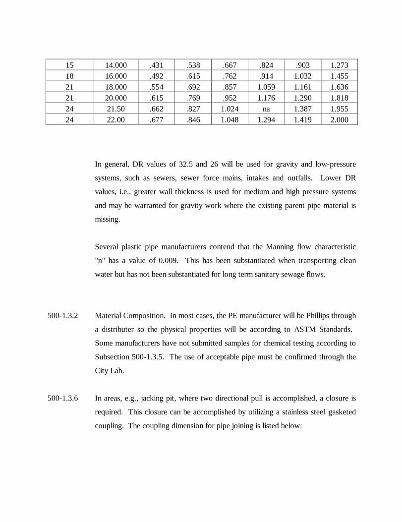
15 14.000 .431 .538 .667 .824 .903 1.27318 16.000 .492 .615 .762 .914 1.032 1.45521 18.000 .554 .692 .857 1.059 1.161 1.63621 20.000 .615 .769 .952 1.176 1.290 1.81824 21.50 .662 .827 1.024 na 1.387 1.95524 22.00 .677 .846 1.048 1.294 1.419 2.000
In general, DR values of 32.5 and 26 will be used for gravity and low-pressure
systems, such as sewers, sewer force mains, intakes and outfalls. Lower DR
values, i.e., greater wall thickness is used for medium and high pressure systems
and may be warranted for gravity work where the existing parent pipe material is
missing.
Several plastic pipe manufacturers contend that the Manning flow characteristic
"n" has a value of 0.009. This has been substantiated when transporting clean
water but has not been substantiated for long term sanitary sewage flows.
500-1.3.2 Material Composition. In most cases, the PE manufacturer will be Phillips through
a distributer so the physical properties will be according to ASTM Standards.
Some manufacturers have not submitted samples for chemical testing according to
Subsection 500-1.3.5. The use of acceptable pipe must be confirmed through the
City Lab.
500-1.3.6 In areas, e.g., jacking pit, where two directional pull is accomplished, a closure is
required. This closure can be accomplished by utilizing a stainless steel gasketed
coupling. The coupling dimension for pipe joining is listed below:

Outside diameter of the liner pipe(inches)*
Minimum length of coupling(inches)
10 5.56315 7.12515 8.62520 10.75020 13.38630 16.000
* National Association of Sewer Service Companies (NASSCO) Recommendation.
The Contractor having cleaned, inspected, and proofed the sewer has ample
opportunity to request spot repairs and correct any conditions which may prohibit
liner insertion. Nevertheless, the Contractor may still be unable to successfully pull
the liner through the existing sewer without experiencing maximum pulling forces.
In most cases, this will be due to Contractor negligence, such as leaving rocks or
debris in the pipeline which binds the liner, or assuming certain defects, such as
sags or offset joints will not present a problem. Other cases may warrant payment
by the City for additional access pits and/or point repair where the sewer has these
defects.
500-1.3.7 Annular grouting has been a subject of considerable debate. Most of the pipe
suppliers contend that grouting the annulus is unnecessary. They normally
recommend that

only immediate upstream and downstream of manholes or structures be grouted
for preventing infiltration.
The practice of grouting the annulus when one-inch or more space is available isrecommended for the following reasons:
1. Provides structural rehabilitation2. Prevents liner from deflecting3. Prevents liner from collapsing4. Prevents long term infiltration5. Prevents liner from moving
6. Locks in service connections7. Eliminates concrete blocking of service connections8. Better than sealing at manholes
9. Extends life from uncertain to 50 years or more10. Provides protection to liner when cleaning11. Resists temperature changes
It is impractical to grout the annulus when less than one-inch space is available. Normal practice is to design the slipliner with the next available thicker walled DR.
500-1.4 Cured-In-Place Liner Pipe (CIPLP)
500-1.4.1 General - The placement of an approved epoxy resin-impregnated flexible tubeshall be installed into an existing conduit by utilizing a hydrostatic head. Whenspecified, this system may be used in sanitary sewers, storm drains and houseconnection sewers. The initial stiffness factor shall conform to the following table.
Nominal Diameterinches
(I.D. of Orig. Pipe) aboveinvert
Stiffness FactorEI (in3 - lbf/in2)
Maximum Allowable Feet*Groundwater
6 328 238

8 328 9610 328 4812 328 2712 1109 9615 1109 4818 1109 2718 2628 6721 2628 4121 5160 9224 2628 2724 5160 54
* Safety factor not included
Note No. 1 Stiffness Factor shall be determined in accordance with ASTM D-2412.
Note No. 2 Safety factor not included.
Note No. 3 Maximum allowable groundwater loads for partially deteriorated pipes.Where groundwater is higher, see Plans or Specifications.
Note No. 4 For ID's larger that 24-inch, see Plans or Specifications.
Note No. 5 The Stiffness Factors listed in the table are initial values for gravity flowcondition. For Pressure Applications, the Stiffness Factors are usually larger.
500-1.4.2 Material Composition and Testing. The tube shall consist of one or more layers offlexible needled felt or an equivalent woven and/or non-woven material capable ofcarrying resin, withstanding installation pressures and curing temperatures, and compatible with the resin system used. The resin used shall be compatible with the

inversion process, and be able to cure in the presence or absence of water. Theinitiation temperature for cure shall be as recommended by the resin manufacturerand approved by the Engineer. The cured-in-place-liner-pipe shall have as aminimum the following initial and long term structural properties for use as a linerand not as a structurally designed pipe for direct burial:
PROPERTY TESTMETHOD
INITIAL LONG TERM
FlexuralStrength
ASTM D790 5,000 psi ------
FlexuralModulus
ASTM D790and ASTM
D2990
300,000 psi 150,000
TensileStrength
ASTM D638 4,000 psi ------
TensileModulus
ASTM D638 250,000 psi 125,000
Note: Initial values are defined in ASTM D-638 and D-790. Long Term Value is definedas 50 years and is determined by ASTM D-2990 Test Method.
The Engineer may, at any time prior to installation, direct the Contractor to obtaincured samples and test them in accordance with the listed ASTM standards fordetermining and meeting properties.
500-1.4.3 Tube Acceptance. At the time of resin impregnation each lot shall be inspected fordefects. The resin shall not contain fillers, except those required for viscositycontrol, fire retardant, or extension of the pot life. Thixotropic agents which willnot interfere with visual inspection may be added for viscosity control. Also, theopaqueness of the plastic coating shall not interfere with visual inspection. Resinsmay contain pigments, dyes, or colors which do not interfere with visual inspectionof the cured-in-place-liner-pipe or its required properties. Additives may beincorporated that enhance the physical and chemical resistant features.

For testing purposes, a lot shall consist of all the tube for a given rehabilitation run.
500-1.4.4 Chemical Resistance. The cured-in-place-liner-pipe epoxy resin system furnishedshall meet the corrosion-weight change requirements of Subsection 210-2.3.3. Proof of meeting these requirements shall be provided to the Engineer for hisapproval, at least 15 days prior to commencement of work.
500-1.4.5 Resin-Impregnated Tube Installation Procedure. Prior to tube placement theContractor shall, in accordance with Subsection 2-5.3, submit shop drawings ofconstruction details. The shop drawings shall include the location and method ofplacement and by-passing location with sufficient detail to assure that the work canbe accomplished without sewage spill.
The OD of the tube being inverted shall be sized correctly allowing for stretch tofill the existing pipe completely. The existing pipe shall be cleaned of anyobstructions or debris prior to tube inversion and shall be approved by theEngineer. The existing pipeline shall be monitored by use of a closed circuittelevision camera. The Contractor shall protect the manholes to withstand forcesgenerated by equipment, water or air pressures used while inverting the tube.
500-1.4.6 Installation. The epoxy resin saturated tube shall be inserted through an existingmanhole or other approved access by means of the installation process and theapplication of a hydrostatic head sufficient to fully extend it to the next designatedmanhole or termination point. The placement procedure shall be required toproduce dimples at the service connections.
500-1.4.7 Curing. After placement is completed a suitable heat source and distributionequipment shall be required to distribute or recirculate hot water throughout thepipe.

Temperature shall be maintained during the curing period as recommended by theresin manufacturer, and approved by the Engineer. After the tube is cured, a cool-down period shall be used prior to opening the downstream stopper, connecting ofservices and returning normal flow back into the system.
500-1.4.8 Service Connections. After the curing is complete and the pipe system is placedinto service, existing service connections shall be re-established. This may bedone without excavation by means of a remote control cutting device operatingwithin small diameter pipe or directly for man entry pipe. A CCTV camera shallbe attached to the cutting device for precise location of service connections andinspection of the finished cured-in-place-liner-pipe.
NTS - reference to pertinent Section paragraphs:
500-1.4.1 General. The unit cost of cured-in-place-pipe (CIPP or Insituform) can be highand at times compares to pipe replacement costs. On projects that are small, orpresent difficult site conditions, unit application costs may approach $20 to $30per inch diameter per linear foot. On large projects where inversion lining is bid asan alternate to replacement, the unit cost is typically in the range of $6 to $9 perinch diameter per linear foot.
Inversion lining has been performed on pipes ranging from 4-inches to 108-inchesin diameter. The design DR is typically 50 maximum and it can be designed toproduce a pipe stiffness over 46 psi, when measured to ASTM D-2412.
The four and six inch sizes are normally for service laterals. The technology israpidly improving, but six inch size mainlines havings service connections aredifficult to connect without excavation.

500-1.4.2 Material Composition and Testing. The liner design is provided in Appendix A. The liner performance, i.e. strengths and corrosion resistance are intimately relatedto the resin employed. Several factors affecting the liner design are as follows:
1. A specific epoxy resin has been tested and meets the corrosion resistancerequirements of Subsection 210-2.3.3.
2. The required buckling strength of the liner will depend on the condition andconfiguration of the existing pipe, external hydrostatic head, soil types,cover depth and traffic loadings. Reference should be made to the variousformulae and sample calculations provided in Appendix A.
3. The existence of groundwater and/or temperature of the soil will affectcure time.
4. The epoxy type resin may bond somewhat to the existing pipe. This canenhance its overall strength in that the various formulae used assumenegligible bonding. It is common practice to use epoxy resin for pressurepipe and service lateral rehabilitation.
500-1.4.6 Inversion. The entire process can be performed without excavation and thereforeis applicable where open-cut construction is undesirable. The liner is fabricated tocorrect pipe perimeter allowing for stretch. The liner is precut to the desiredlength and one end is sealed permitting total inversion. In most cases, the resinadded in the Contractors shop is under controlled conditions. The liner is thenpacked in ice and transported to the construction site in a temperature controlledtruck.
500-1.4.7 Curing. Despite the claims from the resin suppliers, INA and the installationContractors, the ultimate permanence of the inversion liner can only be gagedovertime. The

process is less than 20 years old and projection for a 50-year life or greater are
unproven. Therefore, to establish that the minimum initial strength requirements
are being met, testing of the finished liner is recommended.
500-1.5 PVC Sewer Lining System
500-1.5.1 General. Polyvinyl Chloride extrusions with annulus grouting shall be installed
for use in sanitary sewers, storm drains and house connection sewers. This
applies to the rehabilitation of small diameter pipe and man-entry pipe in terms of
materials and installations.
500-1.5.2 Material Composition. Materials shall conform to Subsection 207-17.2.
500-1.5.3 Material and Equipment Acceptance. At the time of manufacture each lot of
plastic strips shall be inspected by the manufacturer for defects, and the physical
properties certified in accordance to the ASTM Standards listed in this Subsection,
or as indicated in the Specifications. The minimum thickness of the plastic strips
and panels shall be as follows:
Nominal Diameterinches
Minimum ThicknessFormer Strip
inches
MinimumJoiner strip
inches
Profile HeightI.D. of Orig. Pipe
inches
8 to 12 0.025 0.025 0.192

15 TO 18 0.030 0.031 0.24224 to 36 0.045 0.058 0.48030 to 72* 0.060 ____ 0.488
* Material dimensional information for the man-entry placement.
The initial stiffness factor shall conform to the following table:
Nominal Diameterinches
(I.D. of Orig. Pipe)above invert
Stiffness FactorEI (in3 - lbf/in2)
Maximum Allowable Feet*Groundwater
8 120 22810 120 11710 240 23312 240 13615 240 7315 600 18418 600 9024 600 3424 1600 9430 1600 5036 1600 27
For ID's larger than 36 inches, see Plans or Specifications

1. Stiffness factors shall be determined in accordance with ASTM D-2412.
2. Safety factor not included. Grout support factor is included.
At the time of delivery, the strips shall be homogeneous throughout, uniform incolor, free of cracks, holes, foreign materials, blisters, or deleterious faults. Fortesting purposes, a production lot shall consist of all strips produced during anywork shift and must be identified as opposed to previous or ensuing production. The Contractor shall furnish and maintain, in good condition, all necessaryequipment as required for the proper execution and inspection of the work.
500-1.5.4 Marking. Each PVC continuous strip on each reel shall be distinctively marked onits inside surface end with a coded number which identifies the manufacturer, stripthickness, minimum profile height, size, material, machine, date and shift on whichthe material was extruded. These markings shall also appear on the PVC strips ata maximum distance between markings of five (5) feet, and shall be visible frominside the completed liner.
500-1.5.5 Chemical Resistance. The PVC and cured sealant/adhesive material furnishedunder this Subsection shall conform to the corrosion weight change requirementsof Subsection 210-2.3.3 chemical solutions at listed concentrations. Proof ofmeeting these requirements shall be provided to the Engineer for his approval atleast 15 days prior to commencement of work.
500-1.5.6 Installation and Field Inspection. The existing pipeline shall be cleaned of anyobstructions and televised. The condition shall be approved by the Engineer priorto insertion of the liner. The plastic strips or panels shall be handled with care toensure that the plastic is

not kinked, gouged or otherwise damaged.The former and joiner strips shall be engaged and an approved sealant/adhesiveshall be injected onto the engaged locks. The Contractor shall ensure that thejoiner strip is continuously engaged.
For man-entry pipe, the PVC panels shall be cut and trimmed to fit as near aspractical to the internal perimeter of the existing conduit. A bead of approvedsealant/adhesive shall be applied to the female locking edge of the former strip. End joins shall be made with the plasticized end sections, which shall overlap thejoint by not less than 4 inches. End joins shall be staggered and shall remain belowthe normal flowline of the sewer.
500-1.5.7 Grouting Annular Space. For small diameter pipe, the annular space between theoutside of the liner and the inside the existing pipe shall be grouted. Grouting ofthe annular space shall be done in such a manner as to prevent damage or collapseof the liner. Grout shall be pumped into the annular space at manholes, serviceconnections and wherever the liner is exposed.
Grout shall conform to Subsection 500-1.3.7.
For man-entry pipe, the grout shall be injected behind the liner by tubes placed ontop of the liner or holes drilled through the liner. Any holes in the plastic shall becovered with a patch of similar material as approved by the Engineer.
500-1.5.8 Service Connections. Service laterals connections shall be re-established with theliner in accordance with manufacturers recommendations as approved by theEngineer.
NTS - referenced to pertinent Section paragraphs:
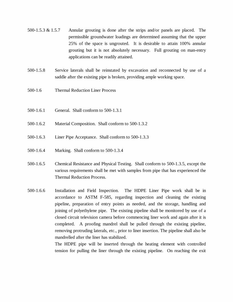
500-1.5.3 & 1.5.7 Annular grouting is done after the strips and/or panels are placed. Thepermissible groundwater loadings are determined assuming that the upper25% of the space is ungrouted. It is desirable to attain 100% annulargrouting but it is not absolutely necessary. Full grouting on man-entryapplications can be readily attained.
500-1.5.8 Service laterals shall be reinstated by excavation and reconnected by use of asaddle after the existing pipe is broken, providing ample working space.
500-1.6 Thermal Reduction Liner Process
500-1.6.1 General. Shall conform to 500-1.3.1
500-1.6.2 Material Composition. Shall conform to 500-1.3.2
500-1.6.3 Liner Pipe Acceptance. Shall conform to 500-1.3.3
500-1.6.4 Marking. Shall conform to 500-1.3.4
500-1.6.5 Chemical Resistance and Physical Testing. Shall conform to 500-1.3.5, except thevarious requirements shall be met with samples from pipe that has experienced theThermal Reduction Process.
500-1.6.6 Installation and Field Inspection. The HDPE Liner Pipe work shall be inaccordance to ASTM F-585, regarding inspection and cleaning the existingpipeline, preparation of entry points as needed, and the storage, handling andjoining of polyethylene pipe. The existing pipeline shall be monitored by use of aclosed circuit television camera before commencing liner work and again after it iscompleted. A proofing mandrel shall be pulled through the existing pipeline,removing protruding laterals, etc., prior to liner insertion. The pipeline shall also bemandrelled after the liner has stabilized.The HDPE pipe will be inserted through the heating element with controlledtension for pulling the liner through the existing pipeline. On reaching the exit

point, the pipe should be pulled beyond this point as advised by the coordinator atthe entrance point. The allowance shall be made on length predicated on thethermal and tension levels developed during the pull. The stretching will berecovered over a period of time depending upon temperature levels above theambient condition. When stabilization is complete, the HDPE pipe should beanchored into the existing pipeline, producing negligible annular space.
500-1.6.7 Service Connections. After stabilization is complete, and the pipe is placed intoservice, the existing service connection shall be reconnected. This may be donewithout excavation by means of a remote control cutting device operating withinthe pipeline. A television camera and a precise locating device shall be attached tothe cutting device for the location of service connections and inspection of thefinished HDPE pipe as approved by the Engineer.
NTS - referenced to pertinent Section paragraphs:
500-1.6.1 The Thermal Reduction Process (Swagelining) has been used successfully,however, very limited for sanitary sewer rehabilitation. If it ceases to be viable, itwill probably be withdrawn from the 1994 Greenbook.
500-1.6.6 Total bypass must be maintained throughout the work. Service laterals within thearea of work must be maintained until reconnected to the newly installed HDPEpipeline.
500-1.7 Deformed HDPE Sewer Rehabilitation System
500-1.7.1 General. Folded High Density Polyethylene (HDPE) extrusions introduced intosanitary sewers and storm drains in order to rehabilitate the existing pipelinesystem without excavation. This method applies to the rehabilitation of 4" thru16" diameter pipe in terms of

materials and installation. The HDPE pipe shall comply with ASTM D-3350 orASTM F-714. Unless otherwise indicated, liner for pipe shall conform to SDR32.5, minimum.
500-1.7.2 Material Composition. Pipe shall be made from HDPE resins complying withASTM D-1248. Type III, Class C, Category 5, Grade P 34, and ASTM D-3350,and shall also meet the requirements of Subsection 207-19.2, except that titaniumdioxide pigment may be substituted for the 2 percent carbon black.
The Contractor shall provide certified test results for approval by the Engineer,from the manufacturer, that the material conforms with the applicablerequirements, including crystallization temperatures.
500-1.7.3 Material and Equipment Acceptance. Material and equipment acceptance shallconform to Subsection 207-19.3.
500-1.7.4 Marking. Marking shall conform to Subsection 207-19.4.
500-1.7.5 Chemical Resistance and Physical Testing. HDPE pipe specimens shall complywith Subsection 207-19.5 except the requirements shall be met with samples frompipe that has experienced the deformation and reforming process.
500-1.7.6 Installation and Field Inspection. HDPE pipe shall be installed as follows:
A. The existing pipeline shall be cleaned of any obstruction, televised, and thecondition approved by the Engineer prior to the insertion of the deformedpipe.
B. A cable shall be strung through the existing pipe to be rehabilitated andattached to the deformed pipe through an existing manhole or access point. The pipe is then pulled through the existing conduit by this cable. Careshall be taken not to damage the deformed pipe during installation.

Appropriate sleeves and rollers shall be used to protect the pipe.
C. When the deformed pipe is in place, the pipe shall be cut and the processingmanifolds (pipe end closing assembly used for heat and pressure controlwithin liner) shall be inserted and secured at both pipe ends. Thetemperature and pressure measuring instruments shall be attached to thedeformed pipe at both ends.
D. Through the use of steam and air pressure, the deformed pipe shall beprogressively reformed to conform to the existing pipe wall. The deformedpipe shall be pressurized up to 14.5 psig, maximum, while the terminationpoint valves are kept open to provide heat flow. The pressure shall beincreased in increments up to a maximum of 26 psig.
E. The Contractor shall cool the reformed pipe to the approved manufacturerrecommendations. When the temperature reduces to 100oF, the Contractorwill then slowly raise the pressure to approximately 33 psig, while applyingair or water for continued cooling. The equipment shall be disconnectedafter ambient temperature is attained.
F. Temperatures and pressures shall be monitored and recorded throughoutthe installation process to ensure that each phase of the process is achievedat the manufacturer's recommended approved temperature and pressurelevels.
500-1.7.7 End Seals. The beginning and end of the new HDPE pipe shall be sealed to therehabilitated pipeline. If sealing material is required, it shall be compatible with theHDPE pipe and shall provide a water tight seal.
500-1.7.8 Service Connections. Existing service connections shall be reinstated through theuse of a remote control unit or excavation.

NTS - reference to pertinent Section paragraphs:
500-1.7.1 Existing pipes having large holes and/or pieces missing may prove to seriouslyinhibit the use of this alternate.
500-1.7.3 It is imperative that the equipment is functioning properly in that the entireoperation is sensitive to temperature and pressure control.
500-1.7.6 The deformed pipe shall be covered with protective wrap or be contained within amobile installation unit. Safety measures shall be implemented at the site, includinginformation dispatch to citizens about the area work. The installation unit shallcontain a properly operating instrumentation control console, steam and pressuregenerating equipment and other auxiliary equipment for process control.
500-1.8 Reinforced Plastic Mortar Liner Pipe
500-1.8.1 General - Fiberglass Reinforced Plastic Mortar (RPM) Liner pipe for use in liningsanitary sewers shall comply with ASTM D-3262. Unless otherwise indicated, theminimum pipe stiffness shall be 18 psi as measured by testing in accordance withASTM D-2412.
Pipe Stiffness (psi) Maximum Hydrostatic Head (ft.)* forUngrouted Installation
18 1036 2146 2772 43
(any pipe stiffness) (0.6 P.S.)

* Groundwater surface to bottom of liner pipe
Note: Safety factor and grout support factor not included.
500-1.8.2 Material Composition - Pipes, joints and fittings shall be made from thermosettingresin, glass fiber reinforcements and silica sand in combinations meeting allrequirements of this Section. Designation per ASTM D-3262 shall be type 1 or 3,liner 2, grade 3 or 5 and pipe stiffness B, C, D, or as indicated in the SpecialProvisions. Rubber gaskets shall conform to the requirements of ASTM F-477.
500-1.8.3 Liner Pipe Acceptance - At the time of delivery the liner pipe shall be free ofcracks, holes, delaminations, foreign inclusions, blisters or other defects thatwould, due to their nature, degree or extent, have a deleterious effect on the pipeperformance. Repairs to the liner pipe, if needed, shall be approved by theEngineer.
For testing purposes, a production lot shall consist of all liner pipe having the samelot marking number but shall not exceed a total of 100 pipes per ASTM D-3262. Pipe length, wall thickness, joint dimensions, pipe stiffness and deflectioncharacteristics shall be verified for each lot per ASTM D-3262 requirements.
500-1.8.4 Marking - Each pipe section shall be marked both inside and outside, at both endsand every five (5) feet on the outside, as follows:
* Manufacturer* Manufacturing Number (Identifies factory location, date, shift and sequence)* Nominal Diameter* Nominal Pipe Stiffness

* ASTM D-3262 and Designation* Lot Number
500-1.8.5 Chemical Resistance and Physical Testing - Liner pipes and gaskets shall conformto the requirements of Subsection 210-2.3.3.
500-1.8.6 Installation and Field Inspection - The existing sewer shall be maintained inoperation during the relining process. Obstructions such as roots, large joint off-sets, rocks or other debris, etc. that would prevent passage or damage to the linerpipe sections shall be removed or repaired prior to installing the liner pipe(s). Liner pipes shall be inserted one section at a time through an access pit constructedabove the existing sewer. The top of the existing sewer exposed in the pit shouldbe removed down to springline level (halfway). Liner pipes shall be inserted spigotend first with the bell end trailing. The pushing force shall be applied to the pipewall end inside of the bell. Maximum jacking load shall not exceed the following:
Safe compressive load (Tons)Nom. Dia. (in)P.S. 18 P.S. 36
18 -- 1720 -- 1924 23 3130 36 5236 52 6642 71 9548 93 13054 123 17160 155 21266 175 24072 209 29278 252 35184 307 422

90 357 48596 411 560
Note: Factor of Safety of 4 is included for longitudinal compressive load.
500-1.8.7 Grouting Annulus - The entire annular space between the outside of the liner andthe inside of the existing pipe shall be grouted. The grout mix and placementprocedure shall be submitted to the engineer for approval, in accordance toSubsection 2-5.3. Grouting of the annular space shall be done in such a manner asto prevent damage or collapse of the liner. Maximum safe grouting pressure (psi)is equal to the pipe stiffness divided by 3.
When grouting is not required, refer to the maximum hydrostatic head for theungrouted installation (Section 500-1.8.1) to determine the appropriate pipestiffness. The liner shall be sealed in both directions at the manholes to a depth of12 inches minimum.
500-1.8.8 Service Connections - Service laterals shall be connected to the liner pipe by useof a mechanical saddle approved by the engineer.
NTS - referenced to pertinent Section paragraphs:
500-1.8.6 Jacking or pipe push pits are constructed approximately 25 feet long by OD plus 2feet wide to accommodate the 20 foot long pipe joints. In the event the existingpipeline alignment is curvilinear, short pipe joints must be utilized. It is necessaryto determine the geometry in advance of the work. Also, the Contractor shouldproof the existing pipeline in advance of the sliplining work.
500-1.8.7 Annulus grouting technology is still in its developing stages. The 1993 GreenbookSupplement should have the latest state of the art.

500-1.8.8 Service connections rarely used on large diameter pipe are occasionally needed. Itis currently recommended that the Inserta-Tee connections are the most proven.
500-1.9 External Inplace Wrap (PVC)
500-1.9.1 General. Where accessible, existing sewer pipes experiencing crown corrosionmay be rehabilitated utilizing a wrap of PVC liner with integral mechanical lockingextensions followed by a cap of reinforcing steel and concrete. The installation ofall plastic liner shall be done in accordance with Plans and Specifications.
Plastic Liner Sheet, weld strip, adhesive products, and cleaners shall be inaccordance with Section 210-2. Prior to plastic liner installation, the existing lineshall be uncovered and pipe exposed below the low flow line as specified. Linershall be applied and secured to the existing pipe, inspected and approved by theengineer prior to placement of reinforcing steel and concrete.
500-1.9.2 Installer Qualifications. Applicators and welders shall be qualified in accordancewith 311-1.2.
500-1.9.3 Preparation of existing pipe for installation of plastic liner. The concrete surfaceshall be etched by sandblasting to develop a slightly granular surface. Whenpermitted by the Engineer, the concrete surface may be acid etched in lieu ofsandblasting.
After sandblasting, the concrete surface shall be thoroughly cleaned of dust. Surfaces etched with acid shall be thoroughly washed with clean water andcompletely dried before applying primer.
500-1.9.3.1 Coverage. The circumferential coverage shall be

the upper 270o unless otherwiseshown on the Plans or indicated in the Special Provisions.
After the liner is installed, the offset of each longitudinal terminal edge of sheetshall not be greater than 12 inches.
500-1.9.3.2 Positioning Liner. Liner installed on the existing pipe shall be positionedwith the locking extensions outward and aligned with or perpendicular tothe longitudinal axis of the pipe.
Liner shall be centered with respect to the field top centerline of the pipe. Linershall be set to fit over the existing pipe joints with the field welded seams locatedon the flat barrel portion of the pipes. Liner shall be closely fitted to the existingpipe. Sheets shall be cut to fit curved and warped surfaces using the minimumnumber of separate pieces.
Prior to installation, the contractor shall indicate to the Engineer the proposedlayout of liner sheets, including the location and type of all field welds.
The Engineer may require shop drawings, per Subsection 2-5.3, or the use ofpatterns or the marking of sheet layouts directly on the existing pipe wherecomplicated or warped surfaces are involved.
At transverse joints between sheets of liner used along the pipeline, the spacebetween ends or edges of locking extensions, measured longitudinally shall notexceed 4 inches.
500-1.9.3.3 Securing Liner in Place. Liner shall be held snugly in place against theexisting pipe by use of adhesive materials, in accordance with linermanufacturer's written recommendations as approved by the Engineer.
Liner shall be bonded to the existing pipe a minimum of six (6) inches along bothlongitudinal bottom terminal
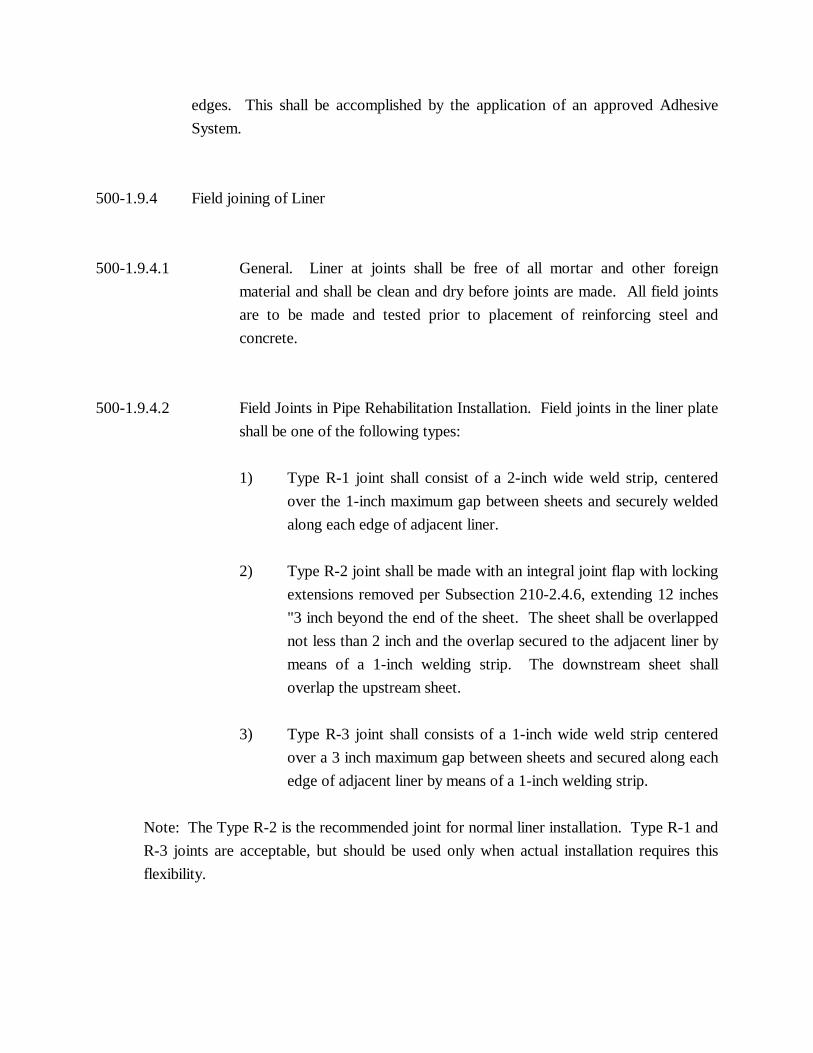
edges. This shall be accomplished by the application of an approved AdhesiveSystem.
500-1.9.4 Field joining of Liner
500-1.9.4.1 General. Liner at joints shall be free of all mortar and other foreignmaterial and shall be clean and dry before joints are made. All field jointsare to be made and tested prior to placement of reinforcing steel andconcrete.
500-1.9.4.2 Field Joints in Pipe Rehabilitation Installation. Field joints in the liner plateshall be one of the following types:
1) Type R-1 joint shall consist of a 2-inch wide weld strip, centeredover the 1-inch maximum gap between sheets and securely weldedalong each edge of adjacent liner.
2) Type R-2 joint shall be made with an integral joint flap with lockingextensions removed per Subsection 210-2.4.6, extending 12 inches"3 inch beyond the end of the sheet. The sheet shall be overlappednot less than 2 inch and the overlap secured to the adjacent liner bymeans of a 1-inch welding strip. The downstream sheet shalloverlap the upstream sheet.
3) Type R-3 joint shall consists of a 1-inch wide weld strip centeredover a 3 inch maximum gap between sheets and secured along eachedge of adjacent liner by means of a 1-inch welding strip.
Note: The Type R-2 is the recommended joint for normal liner installation. Type R-1 andR-3 joints are acceptable, but should be used only when actual installation requires thisflexibility.

500-1.9.4.3 Installation of welding strips shall be in accordance with 311-1.5.4.
500-1.9.5 Protection and repair of liner shall be in accordance with 311-1.9.
500-1.9.6 Field testing shall be in accordance with 311-1.10 and 210-2.3.6.
500-1.9.7 Steel Reinforcement
500-1.9.7.1 General. Before placing reinforcement steel, the Contractor shall submit areinforcing steel placing plan in accordance with the provisions of ShopDrawings, per Subsection 2-5.3.
Reinforcing bars shall be placed in accordance with the size and spacing shown onthe Plans. They shall be held in position by the use of concrete or plastic chairswhen chaired against the plastic liner. Metal chairs shall not be allowed forchairing against the plastic liner.
Caution shall be taken when installing reinforcing steel to ensure againstpuncturing or damaging the liner. If damage occurs to the liner, the liner shall berepaired and retested.
500-1.9.8 Concreting Operations
500-1.9.8.1 Concrete Placement. Concrete placed against liner shall be carefullyconveyed, deposited and consolidated so as to avoid damage to the linerand to produce dense concrete securely anchoring the locking extensionsinto the concrete. Internal vibrators shall be used to consolidate concretewith particular attention along the lower terminal edge of the liner.

500-1.9.8.2 Forms. Often the trench walls themselves serve as the outer form for thenew concrete encasement. When outer forms are required, they shall be ofsuitable material and a type, size, shape, quality and strength to ensureconstruction as designed.
NTS - referenced to pertinent Section paragraphs:
500-1.9.1 The External Inplace PVC Wrap will probably not be used often, however,occasionally a Point Repair or short distance repair should prove to be viable. When pipelines experience surcharging, this method should normally not beconsidered.
500-1.9.3 The excavation of the existing pipeline and careful cleaning around the pipeline ismandatory in advance of the wrapping.
500-1.10 Folded PVC Sewer Rehabilitation System
500-1.10.1 General. Folded Polyvinyl Chloride extrusion material shall be introducedinto sanitary sewers and storm drains in order to rehabilitate the existingpipeline system without excavation. This method applies to therehabilitation of 4" thru 12" diameter pipe in terms of materials andinstallation. The dimension ratio shall be DR 35 in relation to the nominalpipe diameter.
500-1.10.2 Material Composition. The folded pipe shall be made from PVC resinshaving a cell classification of 12334-B or 12454-B, as defined in ASTM D-1784. The pipe shall also be in conformance to Subsection 207-17.2.2,except for the dimensional requirements.
500-1.10.3 Material and Equipment Acceptance. At the time of manufacture, theextruded material shall be
inspected for defects and physical properties in accordance to the ASTMD-1784, or as indicated in the Special Provisions.
At the time of delivery, the material shall be homogeneous, free of defects, cracks,holes, blisters, foreign materials or other deleterious faults. The material shall alsoconform to the requirements listed in Subsection 207-17.4.2.
The Contractor shall furnish and maintain, in good condition, all equipmentnecessary for proper execution and inspection of the work.
500-1.10.4 Marking. Marking shall conform to the requirements of Subsection 207-17.2.1.
500-1.10.5 Chemical Resistance and Physical Testing. The PVC material shall betested in accordance with Subsections 207-17.5 and 210-2.3.3. Thevarious requirements shall be met with samples taken from pipe that hasexperienced the folding and rerounding process.
500-1.10.6 Installation & Field Inspection:
A. The existing pipeline shall be cleaned of any obstacles, televised,and the condition shall be approved by the Engineer prior to theinsertion of the folded pipe.
B. A heat containment tube shall be placed inside the host pipe for theretention of heat necessary to soften the folded pipe.
C. A cable shall be strung through the existing pipe to be rehabilitatedand attached to the folded pipe through an existing manhole or

access point. The heated flexible pipe is then pulled through theexisting conduit by this cable. Care shall be taken not to damagethe folded pipe during installation.
D. After it is fully extended within the existing pipe, the folded pipeshall be cut off at the starting point.
E. Through the use of steam and air pressure the folded pipe isprogressively unfolded and rounded to conform to the existing pipewall providing a tight-fitting pipe within a pipe.
F. The Contractor shall cool the rounded pipe to a temperature asapproved per manufacturer recommendation before relieving thepressure required to hold the rounded pipe against the existing pipewall.
G. Temperatures and pressures shall be monitored throughout theinstallation process to ensure that each phase of the process isachieved at the desired temperature and pressure levels.
H. Repairs to the finished folded pipe, if needed, shall be approved bythe Engineer.
500-1.10.7 End Seals. When required by the Engineer, the beginning and end of thenew PVC pipe shall be sealed to the host pipeline structure in order toprevent water movement between the two systems. The material shall becompatible with the PVC pipe and shall provide a water tight seal. Sealantsystems and materials shall conform to the requirements of Subsection 210-2.3.3.
500-1.10.8 Service Connections. Existing service connections shall be reinstatedthrough the use of a remote control unit or excavation.

NTS - referenced to pertinent Section paragraphs:
500-1.10.1 Existing pipes that have pieces missing may prove to seriously inhibit theuse of this alternate. The heat containment tube should provide somesupport for the PVC pipe liner.
500-1.10.3 It is imperative that the equipment is functioning properly in that the entireoperation is sensitive to temperature.
500-1.10.6 The deformed pipe shall be covered with protective wrap or be containedwithin a mobile installation unit. Safety measures shall be implemented atthe site, including information dispatch to citizens about the area work. The installation unit shall contain a properly operating instrumentationcontrol console, steam and pressure generating equipment and otherauxiliary equipment for process control.
SECTION 500-2 - MANHOLE AND STRUCTURE REHABILITATION
500-2.1 Requirements
500-2.1.1 General. This section covers the various manhole and structure rehabilitationmaterials and methods. The type(s) of rehabilitation materials and methods for agiven project shall be designated on the Plans. The Engineer shall require testingof the materials and methods for compliance with these requirements prior todelivery to the job site and/or prior to acceptance depending upon the alternateselected.
500-2.1.2 Manhole Steps. Manhole steps shall be installed or removed as indicated on thePlans or Special Provisions.

500-2.1.3 Safety. Contractor shall comply with all Federal, State, Local and CAL OSHAsafety regulations. Contractor's personnel shall be certified for confined spaceentry.
500-2.1.4 Removal and Disposal. Contractor shall be responsible for removal and disposalof all debris removed during the cleaning and rehabilitation process. Contractorshall comply with all Federal, State and Local regulations regarding disposal ofdebris.
500-2.1.5 Measurement and Payment. Manhole and structure rehabilitation shall bemeasured along the longitudinal axis between the ends of the manhole or structureas shown on the plans to the nearest 0.1 foot.
Payment for structures, including but not limited to manholes, junction structuresand lampholes shall be made at the contract unit bid price for each structure andshall be full payment for point repair and rehabilitation for each structure completein place including all labor, material, tools, equipment, apparatus and incidentalsnecessary for excavation, backfilling, reconstructing inverts, furnishing andinstalling castings, restoration of the street or ground surface, and all otherrequired work.
500-2.2 Manhole Performing System
500-2.2.1 General. This Subsection describes the installation of the Integral Locking PVCLiner by temporarily erecting a form inside an existing manhole and filling theannular space between the erected form and the existing manhole wall withconcrete or other approved materials that will result in a new PVC lined monolithicmanhole within the old one. This work is for sanitary sewer manholes. The samepreforming system can be utilized for storm drain manholes, except when indicatedon the plans or special provisions, the PVC liner may not be required.

500-2.2.2 Concrete. Concrete, unless otherwise specified by the Engineer, shall be Class560-C-3250 per Subsection 201-1.1.2.
500-2.2.3 Integral Locking PVC Liner. The liner shall comply with the applicablerequirements in Sections 210-2 and 311.1, unless shown otherwise on thedrawings or specifications.
500-2.2.4 Chemical Resistance and Physical Testing. The Intregal Locking PVC Liner shallmeet the requirements of Subsection 210-2.3.3.
500-2.2.5 Installation and Field Inspection. The manhole walls and base shall be free of loosedebris by brushing or low pressure washing. Steps or obstructions that prohibitproper erection of the interior formwork shall be removed to a depth of 1 inchminimum inside the structure. The formwork shall be installed in a manner thatsubstantially fits the existing walls of the manhole and creates an equal andapproximate three (3) inch annular space. Concrete or other materials, asindicated on the plans or special provision, shall be used to fill the annular space. The installation of the Integral Locking PVC Liner shall comply with Section 311-1.
500-2.2.6 Service Connections. Existing lines to the manholes shall be extended through thenewly formed manhole wall. The exposed concrete surfaces within the manholeshall be protected as indicated on the plans or special provisions.
NTS - reference to pertinent Section paragraphs:
500-2.2.2 Concrete. Normal slump test should be run on each concrete pour for assuringproper quality.

500-2.2.5 Installation and Field Inspection. It is important to remove all deterioratedconcrete, down to concrete that is intact, and structurally sound, in order tofacilitate a good bond for the new concrete pour. Care should be taken at the baseof the steel forms for proper seating and protection of all inlet/outlet piping.
500-2.2.6 Service Connections. The service laterals entering the manhole should becomplete, providing total protection to the bare concrete.
500-2.3 PVC Manhole and Wet Well Lining Systems
500-2.3.1 General. This Subsection describes the installation of the PVC Liner by placingthe liner strips so that an annular space is created between the PVC Liner and theexisting manhole/wet well. This annular space is then filled with cementitiousgrout or other approved materials that will result in a monolithic manhole/wet wellwithin the existing manhole/wet well.
500-2.3.2 Materials
500-2.3.2.1 PVC Liner. The PVC Liner shall comply with the applicable requirementsin Sections 500-1.5 (PVC Sewer Lining System).
500-2.3.2.2 Grout. Cementitious grout or other approved materials shall conform toSubsection 500-1.1 and as indicated on the plans or special provisions.
500-2.3.2.3 Sealant/Adhesive. Sealant/adhesive shall be as indicated on the plans orspecial provisions.
500-2.3.3 Chemical Resistance. The PVC material and sealant/adhesive furnished under thisSubsection shall
conform to Subsection 210-2.3.3.
500-2.3.4 Installation and Field Inspection. Surface preparation shall consist of throughcleaning to remove all loose material and surface contaminants.
Any protrusions on the wall surface which interfere with the installation of the linershall be removed. The Contractor, when required, shall provide for the flow ofsewage around the manhole/wet well designated for lining. Installation shall beaccomplished by either manually spirally winding the PVC Strip or manuallyplacing the PVC Panels and by engaging the complimentary locks (male/female) atthe edges of the strips/panels in a manner which creates the annular space, asspecified and approved by the Engineer.
A bead of sealant/adhesive, approved by the Engineer, shall be applied to thefemale locking edge of the strip/panel prior to engaging the locking edges. Cementitious grout or other approved materials, as specified by the Engineer andas indicated on the plans or special provisions, shall be used to fill the annularspace. The grout mix and placement procedure shall be submitted to the Engineerfor approval in accordance with Subsection 2-5.3. Grouting of the annular spaceshall be done in such a manner as to prevent damage or collapse of the liner. Anyholes in the plastic shall be covered with a patch of similar material as approved bythe Engineer. The installation of the PVC Liner shall comply with the applicablerequirements of Subsection 500-1.5.
500-2.3.5 Service Connections. Service connections shall be reestablished with the liner inaccordance with manufacturers written recommendations as approved by theEngineer.
NTS - referenced to pertinent Section paragraphs:
500-2.3.2.2 Concrete. Normal slump test should be run on each concrete pour for assuringproper quality.

500-2.3.4 It is important to remove all deteriorated concrete, down to concrete that is intact,and structurally sound, in order to facilitate a good bond for the new grout pour. Care should be taken at the base of the PVC liner for proper seating and protectionof all inlet/outlet piping.
500-2.3.5 Service Connections. The service laterals entering the manhole should becomplete, providing total protection to the bare concrete.