appendix b perations phase treatment measureso
TRANSCRIPT

_____________________________________________________________________________________________________________________________________________________________________
1
Appendix B
Operations Phase Treatment Measures
This appendix provides information on treatment options available for use during the operational phase of a project. They may be either structural or non-structural measures.
The distinction between operations-phase and construction phase treatment measures is not always clear, because there may be times when measures used during construction, may also be employed during the operations phase of an infrastructure project. An example is where a sediment settling basin (C4) is later adapted as a permanent measure - for example as a detention basin ahead of a constructed wetland. Where there is an option to utilise or adapt ”temporary” measures for long-term pollution control benefits, this has been referred to in appropriate parts of the text.
Additional information on the design of treatment measures can be obtained from the Technical Manual for Urban Design in Greater Adelaide at the link below: http://www.sa.gov.au/subject/Housing,+property+and+land/Building+and+development/South+Australia's+land+supply+and+planning+system/Water-sensitive+urban+design
B Superseded/repealed from 1 November 2021 – refer to
https://www.dit.sa.gov.au/standards/environment

APPENDIX B – Protecting Waterways Manual
________________________________________________________________________________________________________________________________________________________________________
2
B1 Permeable Paving Pollutant removal Cost Optimal
catchment area
Dissolved Fine Sediment
Assoc.
Fine Coarse Gross Capital On-going
Low Mod. Mod. High Low Mod.-High
Mod. Up to 2 ha
Neg. < 10%; Low 10 to 40%; Mod. 40 to 60%; High 60 to 80%; V. high 80 to 100%
General Description Permeable paving permits runoff to infiltrate the pavement surface to the underlying soil, thereby reducing direct runoff. It is suitable for areas with light traffic loads and low sediment loadings, such as carparks, parking bays and bike paths or lanes.
There are two broad forms of permeable pavement: one type comprises an asphaltic layer of gap-graded coarse aggregate, cemented by bitumen, followed by a filter course which is layered over a stone reservoir. The other form uses a modular-type paving, with the spaces between the paving permitting infiltration. Removal of particulates is achieved by filtration or absorption to soil particles. Specific, up-to-date information should be sought from the Stormwater Industry Association secretary (see reference at the end of this section), who will be able to provide up-to-date contact details for manufacturers and products.
Advantages Retains pollutants close to their source (i.e. a source-control practice).
Reduces runoff and may reduce local flood peaks.
Can be more aesthetic than conventional drainage system or conventional paved car-park design.
Limitations Only suited to areas with light traffic loading.
Not extensively tested within Australia at this time.
Potential to clog the surface if inappropriately used – pretreatment to reduce sediment may be essential in some cases.
Accompanying Measures Essential Because permeable pavements are particularly prone to clogging failure when the
sediment load is moderate or high, appropriate pre-treatment (sediment removal) devices may also be necessary prior to runoff entering the permeable paving area.
Non-essential Porous pavement is often underlain by a constructed deep gravel bed, which acts as
a temporary storage until the water percolates into the surrounding soil.

APPENDIX B – Protecting Waterways Manual
________________________________________________________________________________________________________________________________________________________________________
3
Permeable pavement may be constructed over a gravel bed, containing a perforated pipe, to collect the percolate for discharge to another site (e.g. stormwater pipes, swales or waterway). In this situation, an impermeable plastic liner should also enclose the bed.
Planning and Design Permeable paving is suitable for areas with light traffic loads and low sediment
loadings, such as car parks or parking bays, bike paths or lanes. They should not be used in areas of anticipated high sediment loading (resulting from either runoff or wind erosion), as this causes surface clogging failure. Currently there is insufficient information regarding their suitability for areas with heavy traffic loads.
The subsoil must be able to support saturated load conditions.
It is important that the soil have a moderate infiltration rate. Low infiltration rates result in an unacceptably long infiltration time whereas, high infiltration rates may cause groundwater contamination.
Inadequate maintenance has been a cause of failure in some cases. Pavement surface maintenance can entail removal of collected pollutants by high suction vacuum cleaners or high-pressure hoses.
Designers should be familiar with the manufacturer's recommendations, and consult with them as necessary.
Construction Clogging failure has been reported in the literature. It is vital to ensure that sediment
resulting from site development activities does not enter the permeable paving area. Pavement surface protection (e.g. using silt fences (C2) or other measures) and paving inspection and maintenance, should be undertaken, as necessary, during the construction phase.
Where design entails infiltration to the surrounding soil, it is important that construction activities do not adversely affect the subsoil infiltration rate (e.g. avoidance of wall or bed ”smearing” or compaction).
Installers should be familiar with the permeable pavement manufacturer's recommendations.
Maintenance Inspection is paramount to successful operation of this measure. Routine inspection
should be undertaken and any holes, cracks or excessively blocked areas noted for appropriate remedial action.
Inadequate maintenance has been a cause of failure in some designs. Pavement surface maintenance entails removal of collected pollutants by high suction vacuum cleaners or high-pressure hoses.

APPENDIX B – Protecting Waterways Manual
________________________________________________________________________________________________________________________________________________________________________
4
References and Further Information • For up-to-date information on permeable paving manufacturers, products and
installation details, contact : The Secretary, Stormwater Industry Association - South Australia.
• Urban Water Resources Centre, University of South Australia (1999) Workshop Notes on Source Control: Stormwater Management Design Procedures. Ed. J. R. Argue.
Figure B1 - 1 Permeable Paving
(Source: CSIRO 1999)
Permeable Paving

APPENDIX B – Protecting Waterways Manual
________________________________________________________________________________________________________________________________________________________________________
5
B2 INFILTRATION TRENCHES Pollutant removal Cost Optimal
catchment area
Dissolved Fine Sediment
Assoc.
Fine Coarse Gross Capital On-going
Low Mod. Mod. High Low Low Mod. Up to 2 ha
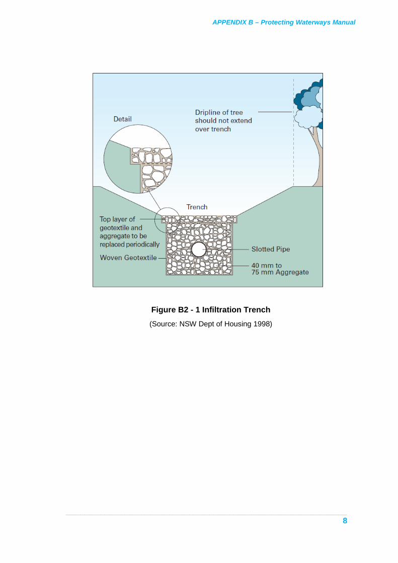
Neg. < 10%; Low 10 to 40%; Mod. 40 to 60%; High 60 to 80%; V. High 80 to 100% General Description An onsite infiltration trench is a shallow, excavated trench, lined with geotextile fabric and back-filled with clean, coarse quarry rubble, into which clean runoff is directed. During inflow the voids in the gravel act as a storage reservoir. This water subsequently infiltrates the soil, the time taken depending on trench design, size and hydraulic conductivity of the surrounding soil. Onsite infiltration systems assist in reducing off-site runoff and may be suited to reducing roof and/or paved area runoff from buildings and car parks; and (if suitably pre-treated with a gross pollutant trap) from the road system.
Advantages Retains pollutants close to their source (ie. source-control practice).
Reduces runoff.
Very effective in reducing the average annual volume of runoff that would otherwise contribute to the street drainage.
Increases soil moisture for local vegetation uptake; may increase groundwater recharge.
May be incorporated into an aesthetically pleasing design.
Limitations Soil characteristics - particularly the influence of increasing soil moisture on soil structure and soil swelling potential, are important factors affecting design and suitability of retention trenches to local site conditions. Trenches sited in soils of comparatively low hydraulic conductivity will require an overflow connector to the drainage network.
Other forms of retention device (e.g. perforated concrete sumps) may be better suited than trenches in some situations (e.g. where there is a limited space to install a device); however, in general, trenches are more cost-effective and easier to construct.
Accompanying Measures Essential Infiltration capability may be reduced by fine sediment deposits. Appropriate pre-
treatment devices for sediment removal may be required. The type of the sediment-control measure(s) necessary will depend on the source of runoff, the anticipated sediment load and its character.

APPENDIX B – Protecting Waterways Manual
________________________________________________________________________________________________________________________________________________________________________
6
A grass filter strip, located upstream of the infiltration zone, or other sediment traps may be required if considerable sediment load is anticipated.
Non-essential Observation pipes may be installed in trenches to permit ongoing examination of
trench performance.
Perforated distribution pipes laid along the base of the trench may permit more even distribution of flow into the trench. This is particularly useful for large trenches that have a single flow entry point and a relatively large contributing catchment.
Trenches may be connected to recharge bores (dependent on design and local site soil/aquifer conditions). This technique is generally best suited to larger systems.
Planning and Design Catchment area, nature of runoff (quality and quantity), soil hydraulic conductivity
and soil characteristics influence the size, design and siting of infiltration trenches.
Soil infiltration rate will affect the design and suitability of this technology. Low infiltration rates will result in unacceptably long infiltration time, conversely high soil infiltration rates may result in groundwater contamination unless appropriate pretreatment is provided.
The influence of increased soil moisture on soil swell potential can be important when considering siting onsite devices in the vicinity of buildings and other structures.
Onsite infiltration trenches may require pretreatment of runoff prior to infusion through the trench.
Inadequate maintenance of pretreatment devices may result in failure of the trench (by bed clogging) or increased soil-groundwater contamination risk.
Retention trenches may be unsuited to areas with a very high groundwater table or highly permeable soils due to the potential to contaminate groundwater. However, they may be used in such situations, provided that inflow runoff is relatively clean.
Observation tubes may be installed in the trench to enable future monitoring of trench water level and quality.
Construction It is vital to ensure that sediment resulting from construction activities does not enter
the trench, and that the design is strictly adhered to. It is also important that gravel fill used in trench construction be clean, well washed, and essentially free of any fines which may otherwise hinder trench performance.
Appropriate inspection and maintenance, entailing removal of collected pollutants above the trench and from any pre-treatment devices, should be scheduled during the construction phase.

APPENDIX B – Protecting Waterways Manual
________________________________________________________________________________________________________________________________________________________________________
7
Installers should be familiar with guidelines for this technology in regard to what is needed to achieve proper functioning of the design, and consult with design engineers as necessary.
It is vital to ensure that "smearing" of side walls and the base of the trench does not occur during trenching. This is particularly important in low permeability clay soils, as wall smearing may severely reduce the capability of the trench to infiltrate captured runoff. The site engineer should inspect the condition of trench walls and bed to ensure that surfaces have not been smeared, immediately prior to laying the geotextile envelope.
Maintenance Inspection is paramount to successful operation of these devices. Water levels in the
trench should be periodically monitored and recorded at observation bore(s), if these have been installed.
All pretreatment devices should be routinely inspected and maintained..
Signs of surface ponding of water in the vicinity of the trench, or other irregularities, should be reported to the design engineer.
References and Further Information • Urban Water Resources Centre, University of South Australia (1999) Workshop
Notes on Source Control: Stormwater Management Design Procedures. Ed. J. R. Argue Chapter 3: Infiltration and Percolation of Storm Runoff - Theory and Examples; Chapter 5: Storages for Runoff Quantity Control (Category 1 Systems); Chapter 7: Storages for Pollution Containment Facilities (Category 2 Systems)..
• NSW Department of Housing (1998) Managing Urban Stormwater: Soils and Construction. ISBN 0731310969. Section 9.
• Maryland Department of the Environment (2000) Maryland Stormwater Design Manual, Volumes I and II. Appendix C13: Method for Designing Infiltration Structures.
APPENDIX B – Protecting Waterways Manual
________________________________________________________________________________________________________________________________________________________________________
8
Figure B2 - 1 Infiltration Trench (Source: NSW Dept of Housing 1998)

APPENDIX B – Protecting Waterways Manual
_____________________________________________________________________________________________________________________________________________________________________
9
B3 KERBLINE TURF STRIPS Pollutant removal Cost Optimal
catchment area
Dissolved Fine Sediment
Assoc.
Fine Coarse Gross Capital On-going
Low Low-Mod. Mod. Mod. Low Low Mod. _
Neg. < 10%; Low 10 to 40%; Mod. 40 to 60%; High 60 to 80%; V. High 80 to 100% General Description Kerbline turf strips consist of a strip of turf at least 400 mm wide, laid behind concrete kerbing (for the full length of the kerbing). Their purpose is to trap and prevent sediment reaching the road surface/stormwater system.
Advantages Aids in preventing water and sediment, originating from verges and median strips,
from entering the street drainage system.
May be preferred to dolomite or similar material, which may scour and contribute to, rather than reduce, stormwater pollution.
Stabilises and protects the median strip/verge from surcharge should drainage in the kerb overflow.
Aesthetically pleasing.
Limitations Kerbline turf strips need to be placed at kerb height, so that the depth of turf acts as a barrier to any water and sediment travelling towards the road from bare areas (such as bare earth and footpaths).
Accompanying Measures Essential The area adjacent to the turf strip should be appropriately stabilised as soon as
possible after laying down the turf strip.
The kerbline strip should be protected from erosion due to surface runoff, or high sediment loadings from adjacent areas, via appropriate means.
Planning and Design Regard should be given to on-going maintainance of the strip and any adjacent developed grass areas. A suitable, easily maintained, drought resistant grass should be used. Kerbline strips should not be used in areas where it may be difficult to maintain.
Construction Install turf strip at kerb height. The depth of turf above the kerb will thereby act as a
barrier to the flow of water and sediment, and will help to filter sediment.

APPENDIX B – Protecting Waterways Manual
_____________________________________________________________________________________________________________________________________________________________________
10
The area behind the turf strip should be protected by paving or vegetation.
The turf strip and other revegetating areas should be temporarily fenced against access, until properly developed.
It is important to ensure that high sediment loads and runoff are directed away from the kerbline strip, at least until the strip has stabilised (i.e. the area behind the strip has revegetated).
Water and maintain the strip until established.
Maintenance Unless there is substantial grass coverage, turf strips will be ineffective in trapping
and filtering verge/footpath runoff. Irrigate and otherwise maintain the strip as required to ensure it remains dense and provides good coverage.
Check the strip for signs of wear. Repair worn or dead sections.
References and Further Information • NSW Department of Housing (1998) Managing Urban Stormwater: Soils and
Construction. ISBN 0731310969. Section 6.

APPENDIX B – Protecting Waterways Manual
_____________________________________________________________________________________________________________________________________________________________________
11
Figure B3 - 1 Kerbline Turf Strip
(Source: NSW Dept. of Housing 1998)
B4 FILTER STRIPS
Pollutant removal Cost Optimal catchment
area Dissolved Fine
Sediment Assoc.
Fine Coarse Gross Capital On-going
Low Low-Mod. Low-Mod.
High Low-Mod.
Low Low <2 ha
Neg. < 10%; Low 10 to 40%; Mod. 40 to 60%; High 60 to 80%; V. high 80 to 100% Description Filter strips are broad, grassed or vegetated areas designed to receive overland (sheet) flow. Runoff is treated primarily by filtration and sedimentation as the runoff is retarded through the grass. Some degree of infiltration may also occur, depending on soil type, texture, the angle of the slope, and whether there are storage depressions within the strip. Overland runoff from filter strips usually enters adjacent channels or watercourses. Filter strips may be sited directly downslope of drainage points on arterial roads, or may follow other treatment measures designed to reduce sediment loads from upstream areas.

APPENDIX B – Protecting Waterways Manual
_____________________________________________________________________________________________________________________________________________________________________
12
Advantages Effective in trapping sediment and some sediment-related pollutants, including heavy
metals, phosphorus and hydrocarbons. Trapped material may be permanently removed, by slow accumulation and transformation into the soil base.
Slows runoff velocity thus reducing peak flows.
Aesthetically pleasing.
Inclusion of other pollution-control features within parts of the filter strip, such as shallow depressions or bunds, can enhance runoff capture and infiltration.
Limitations In order for the filter strip to be effective, the grass or vegetation needs to be dense and well maintained and the strip at least 15 metres wide. A major factor in deterioration of filter strips is erosion and channelisation, which can result from failure to maintain vegetation. Filter strips are intended to receive sheet flow (for example, from adjacent road strips), not concentrated flows. Any concentrated flow entry point will need special provision to ensure erosion of the filter strip will not result. Flow spreading may be used to achieve sheet flow. The ability of these devices to trap and remove sediment and related pollutants reduces when transverse slopes exceed 5% due to increased flow velocities.
Accompanying Measures Essential Where necessary, appropriate pollutant trapping and erosion protection technologies
should be employed where concentrated flows enter the filter strip, for example use of outlet protection, (B16), for drains entering the filter strip, or, in low flow situations, the use of flow “level spreaders”.
An appropriate downslope receiving system (e.g. swale, watercourse or waterbody, road surface, etc.).
Non-essential Potential exists to incorporate shallow depressions within the filter strip, to improve
water retention and infiltration. However, it is important that the down slope side is shallow and well vegetated, in order to prevent erosion occurring when depressions overtop.
Use an appropriate grass species or wetland vegetation which can provide a dense coverage.
Planning and Design
To be effective, filter strips need to be at least 15 m wide.
A major factor in deterioration of filter strips is erosion and channelisation. Filter strip slopes should not exceed 5% and preferably should be less than this, to minimise this risk and promote sediment trapping.

APPENDIX B – Protecting Waterways Manual
_____________________________________________________________________________________________________________________________________________________________________
13
Filter strips are intended to receive sheet flows, not concentrated flows. Concentrated flow entry points should receive particular consideration to ensure that erosion does not result. Concentrated loads may be spread across the width of a filter strip via check banks, rip-rap mattresses, or other means appropriate for the site, which are laid normal to the slope.
Filter strip treatment results primarily from physical filtration. Consequently, its performance depends on the degree of vegetation cover. It is important to use appropriate, easily maintained, drought resistant grasses which can provide a high degree of coverage.
Construction Ensure filter strips are constructed to specification, with particular regard given to
slope, angle and the avoidance of depressions or drainage paths that may concentrate flow.
Ensure that revegetation proceeds rapidly, and is not impaired by other construction activities. However, where possible, time the construction of filter strips to coincide with low rainfall periods or seasons. Silt fences (C2) can be used to provide protection to the strip and/or watercourse during revegetation.
Maintenance Well-functioning filter strips will require comparatively little maintenance. The most
important maintenance consideration involves preserving a dense grass cover. This will require routine inspection, watering, weeding, reseeding, and fertilising as necessary. Inspect to ensure water ”channelisation” is not occurring.
Inspect the filter strip for damage particularly at locations of concentrated inflow and take remedial action where necessary.
References and Further Information • Environment Protection Authority - SA (1997) Code of Practice for Local, State and
Federal Government. Section 5.
• NSW Environment Protection Authority (1997) Managing Urban Stormwater - Treatment Techniques, EPA 97/97. ISBN 0 7310 3886 6 X
• NSW Department of Housing (1998) Managing Urban Stormwater: Soils and Construction. ISBN 0731310969. Section 6.3.5.
• CSIRO (1999) Urban Stormwater: Best Practice Environmental Management Guidelines. Prepared by the Stormwater Committee. Pub. CSIRO Publishing. ISBN 0 643 06453 2 (Chapter 7).

APPENDIX B – Protecting Waterways Manual
_____________________________________________________________________________________________________________________________________________________________________
14
Figure B4 – 1 Filter Strip (Source: CSIRO 1999)

APPENDIX B – Protecting Waterways Manual
_____________________________________________________________________________________________________________________________________________________________________
15
B5 VEGETATED SWALES Pollutant removal Cost Optimal
catchment area
Dissolved Fine Sediment
Assoc.
Fine Coarse Gross Capital On-going
Low Low-Mod. Low-Mod.
Mod.-High
Low Low Low <2 ha
Neg. < 10%; Low 10 to 40%; Mod. 40 to 60%; High 60 to 80%; V. high 80 to 100% Description Swales are vegetated or grass-lined channels that receive and transport concentrated flow. They may be used in place of conventional kerb–and–gutter and underground pipe systems where space permits, or installed in road medians, verges, carparks or depot areas. Although the primary purpose of vegetated swales is to convey runoff, they may also serve as a pretreatment technology prior to other treatment measures. Pollutant removal is achieved primarily by filtration through grass cover, with some degree of sedimentation and infiltration as runoff is retarded. However, this is only effective during low flow events. High flows, induced by larger storms, will produce flow well above the grass level and consequently little pollutant filtering or attenuation will result during such occasions.
It is important to ensure that swales are properly designed to prevent bank and bed erosion. The channel bed should be gentle (less than 4%) or where the natural slope is steeper (up to 6%) the channel bed should be stepped or riffled to achieve this result. Swales should not be located in highly erodible soils or left un-vegetated.
Advantages Potential to trap, and possibly remove, sediment and sediment-associated pollution,
such as heavy metals and hydrocarbons.
Reduced runoff velocity and peak flows, compared to a conventional pipe or concrete-lined stormwater conveyance system.
Aesthetics: swales do not necessarily need to be straight!
Swales can be modified to improve runoff storage and pollutant sedimentation by the inclusion of small barriers “check dams” across the direction of flow, and/or by installing infiltration trenches beneath the swale.
Swales can be modified to take higher flows by combining with conventional pipe systems.
Limitations Swales should only be used where water velocity is low and channel bed slopes are gentle. Swale deterioration can result from a failure to maintain vegetation, or failure to adequately protect the swale bed and bank from scouring.

APPENDIX B – Protecting Waterways Manual
_____________________________________________________________________________________________________________________________________________________________________
16
ACCOMPANYING MEASURES Essential Appropriate erosion protection measures, where necessary. For example, scour
protection (B16) at locations of concentrated inflow points or the outside bends of the swale check dams (small, low-level dams built across a drainage swale or waterway) to reduce grade or Stepping down (riffling) (B17) of the channel bed , can be introduced to limit channel slope and flow velocity.
Non-essential Potential exists to incorporate check dams, open dry or wet basin areas, infiltration
trenches or conventional pipe drainage, etc. into swale design.
Planning and Design Care must be taken in designing swales to ensure that erosion is unlikely to result.
The swale bed slope should be limited to 4% or less. Slopes up to 6% can be accommodated if small check dams are located in the swale to reduce flow velocity. The velocity during the design flow event should be calculated to determine whether it is less than the scouring velocity. If not, the design should be appropriately amended. A bypass for high flows or stormwater drain inlets may be considered to prevent large, concentrated flows eroding the swale.
Subsurface infiltration trenches (e.g. gravel-filled trenches), to promote infiltration from the base of the swale may be incorporated into the design, to improve retention/infiltration, particularly if bed slopes are less than 2%.
Appropriate scour or other erosion protection measures should be considered for concentrated inflow points and where flow velocities might be relatively high (e.g. outside of bends for non-linear swales).
Swales should be a trapezoidal shape with minimum and maximum bed widths of 0.6 m and 2.5 m and a minimum swale length of 30 metres.
Side slopes should not exceed 3:1. (Some references suggest 2:1, with possible provision of permanent stabilisation). If the swale is to be mowed slopes should enable easy access for mowing or maintenance.
Maximum flow depths during the design storm should be equal to one-third of the grass height in infrequently mowed grass, or half height of regularly mowed grass, to a maximum of 75 mm. Greater flows are appropriate for swales designed to convey floodwaters.
Swales do not necessarily need to be straight and should be blended with surrounding land forms to ensure they are aesthetically pleasing. They may also incorporate other aesthetic features, such as shallow ponds.
Swales should be established with turf or erosion control matting and direct seeding (B17) or other appropriate forms of stabilisation.
APPENDIX B – Protecting Waterways Manual
_____________________________________________________________________________________________________________________________________________________________________
17
Construction Ensure swales are constructed to specification.
Ensure that re-vegetation proceeds rapidly and that swales are not operational (receiving runoff) until completely vegetated and all scour protection and other measures installed. Care should be taken to ensure that the channel bed is not compacted by machinery during construction, as this will result in reduced vegetation growth and/or infiltration.
Maintenance Well-functioning swales require relatively little maintenance. The single-most
important maintenance consideration is to preserve a dense grass or vegetative cover over the swale. This requires routine inspection, watering, weeding, and reseeding as necessary.
Swales should be inspected for erosion and remedial action undertaken where necessary.
References and Further Information • NSW Environment Protection Authority (1997) Managing Urban Stormwater -
Treatment Techniques., EPA 97/97. ISBN 0 7310 3886 6 X
• NSW Department of Housing (1998) Managing Urban Stormwater: Soils and Construction. ISBN 0731310969. Section 9.
• CSIRO (1999) Urban Stormwater: Best Practice Environmental Management Guidelines. Prepared by the Stormwater Committee. Pub. CSIRO Publishing. ISBN 0 643 06453 2 (Chapter 7).
• Maryland Department of the Environment (2000) Maryland Stormwater Design Manual, Volumes I and II. Section 3.5.1
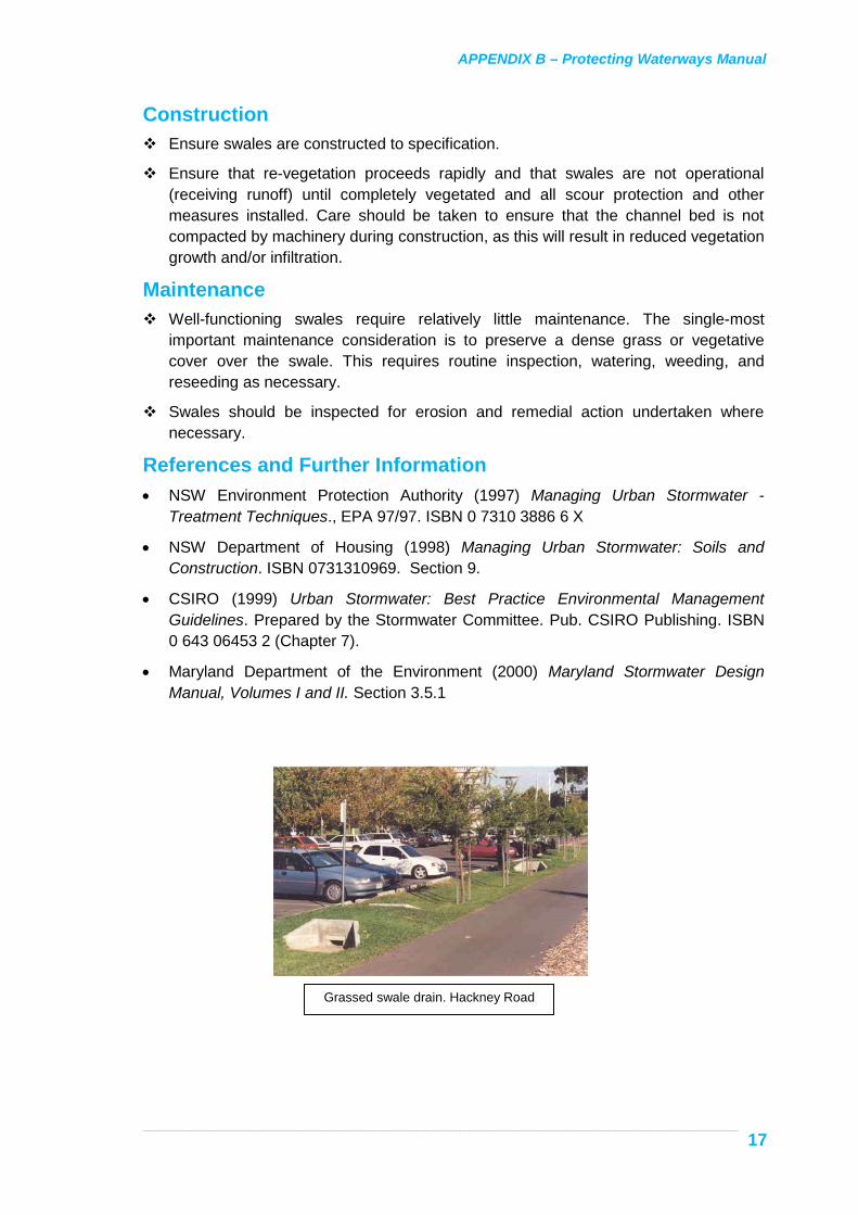
Grassed swale drain. Hackney Road

APPENDIX B – Protecting Waterways Manual
_____________________________________________________________________________________________________________________________________________________________________
18
Figure B5 – 1 Grass Swale (Source: CSIRO 1999)
Swale Drain Swale Drain Cover
Heavily vegetated swale. Kinfaun Estate, Victoria. Photo courtesy of Associate Professor Tony H F Wong,
Monash University.

APPENDIX B – Protecting Waterways Manual
_______________________________________________________________________________________________________________________________________________________________________________
19
B6 OIL/GREASE SEPARATORS
Pollutant removal Cost Optimal catchment
area Dissolved Fine
Sediment Assoc.
Fine Coarse Gross Capital On-going
Neg. Low Low Mod. Low-Mod.
Mod. High <0.25 ha
Neg. < 10%; Low 10 to 40%; Mod. 40 to 60%; High 60 to 80%; V. High 80 to 100%
Description Oil/grease separators are usually concrete or brick built chambers, designed to achieve a three-stage quality improvement of inflow as it passes through consecutive chambers. They are most applicable in small catchments, particularly where there may be a higher than usual presence of hydrocarbons, such as parking bays or fuelling areas in depots.
The primary chamber, containing a permanent pool of water, functions as a sedimentation bay and removes gross matter. It drains through a coarse-screened orifice into the next chamber, which is designed to promote removal of hydrocarbons via floatation and entrapment. Trapped hydrocarbons remain on the surface water, until removed or absorbed onto sediment particles. Flow from the chamber is regulated via an inverted pipe. The third chamber collects and disperses flow to the stormwater system. This chamber may utilise a raised orifice outlet, to improve sediment entrapment and regulate outflow.
Advantages Effectiveness in trapping sediment and hydrocarbons.
Suitability for treatment of stormwater from areas expected to have a significant vehicular pollution (particularly hydrocarbon) content, such as car parks and vehicle depots.
Are generally suitable for retrofitting in existing drainage systems.
Subsurface installation and thus minimal visual impact.
Limitations They rely on consistent maintenance to be of value, as the pollutants are only separated, not removed, until they are finally cleaned out of the facility. This must be performed regularly, as turbulent inflow will re-mobilise previously trapped pollutants.
Accompanying Measures None essential

APPENDIX B – Protecting Waterways Manual
_______________________________________________________________________________________________________________________________________________________________________________
20
Planning and Design In order to reduce the size (and cost) of these devices, they should generally be only
be considered for receiving runoff from areas likely to be a cause of oil-contaminated runoff risk, such as fuelling areas on depots or car parks. For such locations, it may be prudent to segregate areas of high-pollution risk from other areas of comparatively clean water (for example, by bunding or prior interception of clean runoff).
Due regard must be given to the need (and expense) to maintain water quality inlets.
These devices perform inadequately during high-flow periods, and should only accept low flows. The design will need to incorporate a high flow system.
Planning/design should allow for ease of access for inspection, maintenance and cleaning.
The inter-chamber screen should not permit forward flow of particles greater than 5 mm diameter.
Construction Ensure the device is constructed and installed to specifications.
Ensure the device receives runoff only from the design catchment area - ie. any bunding, or other necessary "flow segregating" technique, is installed according to design specification.
Maintenance Regular cleaning is essential to ensure the proper functioning of water quality inlets.
Ensure that regular inspection and cleaning are undertaken. The generally recommended cleaning schedule is once per month.
Cleaning of each chamber should be undertaken by vacuum pump tanker. The turbulence of the pump produces slurry, that can be pumped to the tanker.
Regular inspection of the chambers for damaged or broken baffles should be undertaken.
The contents of oil/grease separators may be hazardous, or otherwise harmful. Occupational health, safety and welfare standards should be adhered to during periods of maintenance, inspection or repair and contents should be disposed of to an appropriate waste disposal facility.
References and Further Information • NSW Environment Protection Authority (1997) Managing Urban Stormwater -
Treatment Techniques. EPA 97/97. ISBN 0 7310 3886 6 X

APPENDIX B – Protecting Waterways Manual
_______________________________________________________________________________________________________________________________________________________________________________
21
Figure B6 - 1 Oil & Grit Separator (Source: WA Water & Rivers Commission 1998)
B7 CATCH BASINS AND LITTER BASKETS
Pollutant removal Cost Optimal catchment
area Dissolved Fine
Sediment Assoc.
Fine Coarse Gross Capital On-going
Neg. Neg. Low Low-Mod.
Mod. Low-Mod.
Device dep.
<1 ha
Neg. < 10%; Low 10 to 40%; Mod. 40 to 60%; High 60 to 80%; V. high 80 to 100% Description These devices prevent gross pollution, such as litter and leaves, from entering and polluting waterways and the formalised underground drainage system.
Litter baskets come in varying designs and sizes and are placed inside side entry pits. Larger gross pollutant traps can be in the form of trash racks which are placed across creeks and watercourses (refer to B14).
Trash or litter baskets are removable metal or plastic baskets installed at side entry pits for entrapment of gross pollutants.

APPENDIX B – Protecting Waterways Manual
_______________________________________________________________________________________________________________________________________________________________________________
22
They are appropriate for retrofitting into existing stormwater drainage networks, as they require concentration and collection of water at the device. There are many proprietary or other configurations within this category of devices, including “dry” and ”wet” configurations. Grated entrance screens (to side entry inlets) may also perform a similar function by trapping gross pollutants. They are placed in roadway side entry pits, so as to intercept the flow and collect rubbish as it enters the pit.
Catch basins are modified versions of regular side entry pits. The simplest catch basin is a side entry pit with a lowered base, which is designed to accumulate sediment. Catch basins are similar in application to litter baskets, although the focus is generally on catching more dense, coarse sediment rather than gross pollution and debris. They only have a small capacity for sediment retention, and without appropriate modification, and regular maintenance, the turbulence within the pit during moderate to high flows may re-mobilise much of the pollution.
Advantages Ability to remove gross pollution.
Removes unsightly litter from waterways.
Best suited for higher litter areas such as shopping centres, shopping malls and strips, schools and train stations.
Limitations A major limitation with this range of devices is the need for regular cleaning. Failure to regularly clean these devices may result in poor pollutant trapping efficacy and an increased likelihood of blocking the stormwater drainage system, leading to increased flood risk. Some devices, such as grated inlets, are easily cleaned and consequently some manuals (e.g. CSIRO, 1999) regard these as having a low-moderate maintenance cost. Other devices, such as litter baskets, which are placed inside the side entry pit, are more difficult to remove for cleaning, and are regarded as having moderate-high maintenance costs. Proprietary devices, except grated inlets, will probably have a moderate-high ongoing cost. Some devices are best cleaned by suction pump.
A larger device further down the catchment may be more cost effective, in terms of maintenance costs, than a series of small devices.
Accompanying Measures Essential Appropriate side entry pit configuration. Generally, devices are designed for the pit
geometry, although some gross pollutant devices, including some proprietary devices, are, essentially, redesigned side entry pits.
Planning and Design Consider flood risk, public safety, potential for vandalism, likely efficacy,
maintenance responsibility, and cost during decision making.

APPENDIX B – Protecting Waterways Manual
_______________________________________________________________________________________________________________________________________________________________________________
23
Currently there are no formal guidelines for most devices. The primary consideration is to ensure that such devices will not have a significant impact on the hydraulics of the pit or pipe system when in a fully blocked condition.
Safety, ease and cost of maintenance should be considered at an early stage.
May be best suited for use in targeting specific high-litter areas, such as shopping centres, shopping malls and strips, schools and train stations.
Consult the Stormwater Services Section for details of proprietary devices.
Construction
Devices generally can be fitted within one day. Fence off as appropriate for public safety until installation is completed.
Maintenance These devices need be maintained to avoid increased flood risk. Typical average
cleaning frequency in areas with high loads is every 4-6 weeks.
Report conditions - i.e. which devices are near-empty, which near-full, etc., during inspections. This may aid in modifying the frequency of the inspection and maintenance schedule or permit a season-based maintenance schedule, in the longer term.
Devices should be periodically checked for damage.
Gross litter may be harmful, appropriate occupational health and safety precautions should be adhered to during periods of maintenance, inspection or repair.
References and Further Information • NSW Environment Protection Authority (1997) Managing Urban Stormwater -
Treatment Techniques. EPA 97/97. ISBN 0 7310 3886 6 X
• CSIRO (1999) Urban Stormwater: Best Practice Environmental Management Guidelines. Prepared by the Stormwater Committee. Pub. CSIRO Publishing. ISBN 0 643 06453 2. Chapter 7.

APPENDIX B – Protecting Waterways Manual
_______________________________________________________________________________________________________________________________________________________________________________
24
Figure B7-1 Cross Section of a Catch Basin (Source: NSW EPA 1997)
Figure B7-2 Litter Basket and Pit (Source: CSIRO 1999)

APPENDIX B – Protecting Waterways Manual
_______________________________________________________________________________________________________________________________________________________________________________
25
B8 INFILTRATION BASINS (DRY PONDS)
Pollutant removal Cost Optimal catchment
area Dissolved Fine
Sediment Assoc.
Fine Coarse Gross Capital On-going
Low Mod. Mod. Mod.-High
Neg. Low-Mod.
High <5 ha
Neg. < 10%; Low 10 to 40%; Mod. 40 to 60%; High 60 to 80%; V. high 80 to 100% Description Infiltration basins, or dry ponds, are excavated impoundments which retain water during small storm events. Base soils need relatively high permeability, to allow for the gradual draining of stored water. The basins are designed to overflow during storm events larger than the design storm. Consequently, such basins serve to reduce runoff rates and volumes, as well as increasing groundwater recharge through infiltration. Some surface water quality gains can be achieved as the sediment settles or is filtered by the subsoil, although the major function of such basins is usually runoff detention, and subsequent reduction in peak flows. High evaporation rates in parts of South Australia may contribute to the efficiency of such basins.
Advantages Reduce peak runoff rates and volumes.
Groundwater recharge.
Can be used in urban residential areas (generally for catchments less than 5 ha).
Litter Baskets

APPENDIX B – Protecting Waterways Manual
_______________________________________________________________________________________________________________________________________________________________________________
26
Limitations Failure may occur from clogging of the basin floor, poor design or poor site selection. Pretreatment and appropriate maintenance procedures should be considered to avoid clogging. ”Off-line” designs, which bypass large storms and their sediment loads, may be incorporated into the design. Basins may accumulate heavy metal contamination, from the stormwater, resulting in groundwater contamination where subsoil is too coarse.
Accompanying Measures Essential If the site is likely to have a high sediment load consider methods for reducing
sediment and possibly gross pollutant loadings entering the basin. Such means include a pre-basin gross pollutant trap to remove coarse sediment, and incorporating a high-flow bypass into the design.
Appropriate vehicle access to the basin floor, for cleaning and maintenance.
Planning and Design Adequate land must be available. Avoid locating basins on fill areas or on or near
steep slopes.
Soil hydraulic loading rate and hydraulic conductivity are key design factors.
Regard should be given to the potential risk of groundwater contamination, particularly where subsoil is highly permeable and/or the seasonal groundwater table rises to close to the bottom of the basin. Subsoil should have a moderate permeability and a deep groundwater table is preferred.
It should be noted that high failure rates (due to clogging) have been experienced in the NE United States. Australian soils generally have a higher percentage of fine particulate consequently, they might be even more susceptible to clogging than overseas experience suggests. If sediment loads are likely to be high pretreatment (e.g. a gross pollution trap) a high flow bypass, and other appropriate measures should be considered, to prevent large deposits of sediment from entering and clogging the basin.
Basins should be designed to allow an even spread of inflow, to limit the risk of clogging parts of the basin. Basin floors should be flat.
It may be possible to install a subsoil drainage system beneath the basin floor, to aid infiltration.
Energy dissipaters should be provided to limit inflow velocity, to maximise settling and minimise resuspension of sediment.
The basin floor and sides should be grassed to reduce erosion and a risk of fine sediment clogging the basin floor.
Easy vehicle access to the basin floor must be provided, for maintenance purposes.
Incorporate a bypass or spillway overflow, for runoff events larger than the design event.

APPENDIX B – Protecting Waterways Manual
_______________________________________________________________________________________________________________________________________________________________________________
27
Consider safety, including the use of appropriate side slopes and inlet/outlet structures. Side slopes should generally be shallow (flatter than 4:1 to 6:1) and warning signs should be posted if ponding depth is significant.
Construction Compaction of the basin floor by heavy equipment must be prevented during
construction. Consequently, only relatively light construction plant should be used, and practices adopted which will minimise soil compaction. The area should be fenced off from heavy equipment.
Some compaction is probably inevitable; therefore, the basin floor should be tilled and leveled.
Infiltration basins should generally not be used as sediment basins during the construction phase. When practical, divert runoff away from the basin site. If the basin is to be used for sediment retention during construction, the floor of the sediment basin should be temporarily raised above that of the proposed final basin floor level. Sediment that accumulates during construction and the additional soil layer may be removed prior to basin operation, leaving a relatively undisturbed (unclogged) basin floor.
Clogging risk is minimised if the basin is not operated until after the site has completely stabilised.
Maintenance Maintenance is a vital factor in ensuring adequate functioning of the basin.
Maintenance should be regular and include periodic removal of deposited sediment, grass mowing and grass maintenance.
The duration of standing water in the basin, or sections of the basin should be compared with the design infiltration period. Presence of water for periods exceeding the design period may indicate clogging problems.
Basin problems such as poor infiltration rates should be remedied in order to prevent severe clogging failure.
Methods for minimising clogging include dredging and tilling to enhance infiltration.
References and Further Information • CSIRO (1999) Urban Stormwater: Best Practice Environmental Management
Guidelines. Prepared by the Stormwater Committee. Pub. CSIRO Publishing. ISBN 0 643 06453 2 Chapter 7
• NSW Department of Housing (1998) Managing Urban Stormwater: Soils and Construction. ISBN 0731310969. Section 9.
• Maryland Department of the Environment (2000) Maryland Stormwater Design Manual, Volumes I and II. Section 3.3 and following.

APPENDIX B – Protecting Waterways Manual
_______________________________________________________________________________________________________________________________________________________________________________
28
Figure B8 – 1a Infiltration Basin (Source: WA Water & Rivers Commission 1998 & NSW EPA 1997)
Figure B8 – 1b Infiltration Basin (Source: WA Water & Rivers Commission 1998 & NSW EPA 1997)
Infiltration Basin. Regent Gardens

APPENDIX B – Protecting Waterways Manual
_____________________________________________________________________________________________________________________________________________________________________
29
B9 SAND FILTERS Pollutant removal Cost Optimal
catchment area
Dissolved Fine Sediment
Assoc.
Fine Coarse Gross Capital On-going
Low Mod. Mod. Mod.-High
Low Mod.-High
Mod.-High
<25 ha
Neg. < 10%; Low 10 to 40%; Mod. 40 to 60%; High 60 to 80%; V. high 80 to 100% Description Sand filters usually comprise a concrete tank (sometimes an open area) containing a bed of sand - or occasionally other medium such as peat, limestone or soil, through which runoff is passed. The filtered water is collected by an under-drain. In order to reduce bed clogging and ensure even sediment distribution pre-treatment to remove coarse sediment is required. Sand filters should be capable of removing some fine sediment and associated pollutants. They have limited ability to remove dissolved pollutants. There are two forms of sand filters: small sand filters (generally serving less than 2 ha) located underground, and larger filters, serving stabilised, largely impervious catchments of up to 25 ha. Larger filters are surface systems which may incorporate topsoil and grass cover to treat flows from floodways or pipe drainage systems.
Advantages They can be retrofitted into existing drainage systems, including underground
installations.
Retain coarse, and some fine, sediments.
Appropriate for areas where constructed wetlands are not feasible.
Limitations Pretreatment and regular cleaning of the filters is necessary to minimise bed clogging. The filters have a relatively large head loss, and relatively low infiltration rate. Because of the potential to clog, they are not suitable for treating runoff from disturbed catchments or other catchments where high sediment export is anticipated.
Accompanying Measures Essential Due to the high potential for bed surface clogging, pretreatment will be necessary.
This entails retention of gross floating material and construction of a gross sediment trap upstream of the filter.
Appropriate access to the filter will be required for cleaning and maintenance. The form of access will depend on filter size, design and maintenance practices.

APPENDIX B – Protecting Waterways Manual
_____________________________________________________________________________________________________________________________________________________________________
30
Planning and Design The performance of filters depends on the characteristics of inflow sediment (such
as particle size and distribution) and on catchment conditions. Clay soils may require a larger filter area. Pretreatment is necessary to remove coarse sediment and gross pollution. The approach sometimes suggested for large sand filters, is an extended detention basin that achieves 60-75% retention of suspended solids for the design storm.
A flow spreader such as a saw-tooth weir should be incorporated into the filter system design to evenly distribute flow across the filter bed.
The filter should be underlain with geotextile fabric over a coarse gravel/underdrain system.
The surface area of the filter can be derived from the formula:
A = V.d K.t.(h+d) where A = surface area of filter (m2) V = volume to be infiltrated (m3) K = hydraulic conductivity (m/h) T = drainage time (h) h = average head above filter [half the storage depth] (m) d = depth of filter (m).
A hydraulic conductivity of 0.033 m/h, a minimum filter media depth of 0.4 m and a filtration time of one third of the mean inter-event period is needed, to permit the filter to dry to maintain aerobic conditions between most rainfall events. The filtration period should be based on rainfall patterns at the proposed site. The Adelaide mean inter-event rainfall is approximately 44 hours (July and August value).
CDM (1993) adopt a sand size of 0.5-1.0 mm; the City of Austin (1998) adopt 0.25-0.5 mm; and ARC (1992) recommends that 10% should pass a 63 µm sieve, and 90% should pass a 500 µm sieve. (See the above-mentioned references cited in CSIRO, 1999).
Large flows in excess of the design storm should bypass the basin by means of a high-flow bypass.
Performance monitoring of sand filters is limited, although results to date suggest comparatively high removal rates for most pollutants. Generally the removal rates are comparable to those of constructed wetlands.
Sand filters should be located in areas accessible for inspection and maintenance.
Construction All components should be installed in accordance with the design.
Filter sand obtained from the supplier should be examined to ensure it meets the design requirements, before being placed.

APPENDIX B – Protecting Waterways Manual
_____________________________________________________________________________________________________________________________________________________________________
31
Care must be taken with the installation (and operation) of sand filters. It is important that filters not be operated until all pretreatment systems are in place.
Maintenance Maintenance is a vital factor in ensuring adequate functioning of the sand filter.
Maintenance should be regular and include removal of deposited sediment and, where applicable (e.g. some large systems) grass mowing and maintenance.
Conditions of the filter should be regularly monitored including how long the filter takes to drain and whether the flow distribution is uniform. The drainage time should be compared with the design drainage period. Presence of water for periods longer than the design drainage period will indicate clogging problems that should be reported to the designers.
Problems should be quickly remedied, in order to prevent severe clogging failure and possible stagnation of water in or above the filter.
References and Further Information • CSIRO (1999) Urban Stormwater: Best Practice Environmental Management
Guidelines. Prepared by the Stormwater Committee. Pub. CSIRO Publishing. ISBN 0 643 06453 2 Chapter 7
• Maryland Department of the Environment (2000) Maryland Stormwater Design Manual, Volumes I and II. Section 3.4 and following.
Figure B9 – 1 Sand Filter
(Source: CSIRO 1999)

APPENDIX B – Protecting Waterways Manual
_____________________________________________________________________________________________________________________________________________________________________
32
B10 BIORETENTION & REED BED SYSTEMS Pollutant removal Cost Optimal
catchment area
Dissolved Fine Sediment
Assoc.
Fine Coarse Gross Capital On-going
Low Low-Mod.. Mod. Mod.-High
Low Mod.-High
Mod. <2 ha
Neg. < 10%; Low 10 to 40%; Mod. 40 to 60%; High 60 to 80%; V. high 80 to 100% Description Bioretention systems are similar to constructed wetlands (B15) in that they can be used to filter stormwater and retain pollutants using a combination of biological and chemical processes. However they are able to provide a higher level of fine particulate and associated contaminant removal than wetlands. Bioretention systems usually involve the use of a grass swale as a pre-treatment facility for the bioretention zone for the removal of coarse to medium sized particulates. The runoff is then infiltrated through a filtration medium, such as an infiltration bed, for the retention of fine particulates and associated contaminants. Bioretention systems are not designed to retain runoff for an extended period of time, instead the filtered runoff is collected at the base of the filtration medium, usually in a perforated pipe, and discharged to the receiving waters.
Reed beds are gravel-filled trenches or beds, planted with wetland plants, through which stormwater runoff is routed. They are also similar to constructed wetlands (B15) in regard to the principal treatment mechanisms - sedimentation, bio-filtration, adsorption, and biological uptake and transformation. There are no guidelines for these systems, and very few studies have been made to determine water quality treatment efficiencies. It is difficult to compare performance between systems, due to differences in designs, climatic conditions, hydrology and plant species and composition. The “Parfitt Square” stormwater management demonstration project in Adelaide incorporates a reed bed system to treat runoff from a small, mixed land-use catchment. Road runoff simulation tests at this site have shown that design is well suited to managing first flush pollutant loads. Water quality improvements are subject to design variables, including bed geometry (to minimise short circuiting), reed bed/catchment area ratio, depth of plant sub-structure, and plant species.
Advantages With care, they may be retrofitted into some existing urban areas.
Retain coarse and fine sediments; suitable for removing “first-flush” pollutant loads
Offers improved amenity to the community
Limitations Pretreatment is necessary to minimise the risk of clogging the reed bed, which may lead to overland flow.

APPENDIX B – Protecting Waterways Manual
_____________________________________________________________________________________________________________________________________________________________________
33
Short-circuiting of flow through the gravel bed should also be avoided through appropriate design, such as a high length : width ratio, or use of baffles within the bed. During extended dry periods, reeds may require watering. Occasional plant maintenance may be required.
Accompanying Measures Essential Due to susceptibility of clogging near the inlet, pretreatment will be necessary. This
entails retention of any gross floating material and construction of a gross sediment trap upstream of the reed bed.
Other Reed beds can be incorporated with other treatment measures, such as filter strips
(B4) for pre-treatment, infiltration trenches (B2) and swales (B5), for receiving treated reed bed flow.
Planning and Design There are no guidelines for designing reed beds. Designers should consult
references on large, constructed wetlands (B15) for information relating to appropriate wetland species. Reed beds should include pretreatment, as discussed above, with a flow-spreader at the inlet, in the form of a saw-tooth weir or comparable method. They should employ a media of relatively coarse gravel, washed free of fines prior to placement, to minimise the risk of clogging. In pervious soils they must be underlain by an impervious liner to prevent excessive seepage. They should be designed on the basis of flow through porous media - overland (above gravel-surface) flow should be avoided in order to improve sedimentation/filtration, and prevent conditions for mosquito breeding.
It is usually appropriate to choose a range of plant species. Species which provide good bed coverage and a relatively deep root structure (e.g. 0.3 to 0.7 metres) are preferred. Aesthetics may also be considered in design of the reed bed and plant species selection.
Plants used in the reed bed may require occasional maintenance; access will be required for watering and, if necessary, occasional removal of accumulating plant litter.
Seek advice from appropriate experts when choosing reed species, and for information regarding plant spacing, planting methods and season, plant maintenance, etc. It may be necessary to install a watering system to maintain the plants during extended dry periods.
Construction Components should be installed in accordance with the design.
The gravel media must be free of fines prior to placement, otherwise, these may wash out of the bed and contribute to runoff pollution.

APPENDIX B – Protecting Waterways Manual
_____________________________________________________________________________________________________________________________________________________________________
34
Care should be taken to ensure that the plants are not damaged during or following planting.
Maintenance Appropriate maintenance is necessary to ensure plant vigour. This may involve
watering during dry periods, and occasional removal of accumulating organic litter from the bed surface.
It is preferable to avoid fertilising, as some of the nutrients may be flushed from the system during subsequent storm events. Generally, wetland plant species will survive in nutrient-low environments.
Seek expert advice should there be problems with the reed bed plants at any time.
The water level in the reed bed should be regularly checked to ensure it is sufficient for plant survival.
References and Further Information • This is an emerging technology for which there is little design information available. A
stormwater treatment system incorporating a reed-bed system has been installed at Parfitt Square, a small inner-suburban catchment, City of Charles Sturt. For more information about the Parfitt Square reed bed project, contact the City of Charles Sturt or [email protected].
• Wong, T., Breen, P & Lloyd, S. (2000) Water Sensitive Road Design – Design Options for Improving Stormwater Quality of Road Runoff. Technical Report 00/1. Cooperative Research Centre for Catchment Hydrology.
• Maryland Department of the Environment (2000) Maryland Stormwater Design Manual, Volumes I and II. Sections 3.1 and 3.2 which incorporate reed bed components.

APPENDIX B – Protecting Waterways Manual
_____________________________________________________________________________________________________________________________________________________________________
35
Figure B10 – 1 Bioretention System
(Source: Wong, Breen & Lloyd, 2000)
Figure B10 – 2 Reedbed
(Source: D.Pezzaniti, University of SA)

APPENDIX B – Protecting Waterways Manual
_____________________________________________________________________________________________________________________________________________________________________
36
B11 IN-LINE GROSS POLLUTANT TRAPS
Pollutant removal Cost Optimal catchment
area Dissolved Fine
Sediment Assoc.
Fine Coarse Gross Capital On-going
Neg. Low Low-Mod.
Mod.-High
High Mod.-High
Mod. Device Dependent
Neg. < 10%; Low 10 to 40%; Mod. 40 to 60%; High 60 to 80%; V. high 80 to 100%
Reed beds. Parfitt Square, Adelaide. Source: D. Pezzaniti.
2000 2002
Bioretention device. Melbourne. Photo courtesy of Associate Professor Tony H
F Wong, Monash University.

APPENDIX B – Protecting Waterways Manual
_____________________________________________________________________________________________________________________________________________________________________
37
Description In-line pollution control devices are designed to be inserted in stormwater pipe systems to remove sediments, oils and gross pollutants. A range of proprietary devices are available. Although most of the devices are gross pollution traps (GPTs), some are capable of also removing some fine sediments and oils. The degree to which the pollutants are removed varies across the range of devices - information which is frequently covered by “commercial in confidence” restrictions. However, some literature relating to capture efficiencies is publicly available. Generally, there are three sub-categories relating to the design capabilities of in-line devices:
Capture of gross pollutants and medium-coarse sediments.
Capture of gross pollutants, and oils.
Capture of gross pollutants, oils and fine-to-medium size sediment.
These devices may be either dry or wet systems (wet systems retain a permanent pool of water). Some are prefabricated devices intended to be fitted into existing stormwater drainage lines, whereas others are cast in place.
All of these devices can be employed as in-line or end-of-line systems.
Advantages Removal of gross pollutants, including litter and organic matter.
Reasonable removal of coarse sediment.
Limitations These systems require quite frequent maintenance (cleaning). At present it is unlikely that there exists any proprietary pollution control device that is capable of consistently removing all of the fine particulates or associated (absorbed) pollutants.
Accompanying Measures Non-essential Proprietary systems are generally designed as “stand-alone” in-pipe or end-of-line
systems.
Planning and Design The primary consideration is to ensure that even when fully blocked these devices
do not have a detrimental impact on the hydraulics of the stormwater system, resulting in flooding in the vicinity, or upstream, of the device.
Ease and cost of maintenance should be considered at an early stage.
Consider flood risk, public safety, likelihood of vandalism, likely performance of the device, maintenance responsibilities, and other appropriate factors, during decision making and device selection. Manufacturers should provide sufficient information about their designs. Contact the Stormwater Services Section for manufacturers’ contact information.

APPENDIX B – Protecting Waterways Manual
_____________________________________________________________________________________________________________________________________________________________________
38
Construction All components should be installed in accordance with design.
Devices should be fitted in as short a time as practical. Fence off the area, for public safety, until installation is completed.
Maintenance Frequent maintenance will usually be required to clean out gross solids and debris,
clean baskets, filters, or other components. The frequency will depend on local conditions.
Devices should be periodically checked for damage.
Gross litter may be harmful. Appropriate occupational health and safety precautions should be used during periods of maintenance, inspection or repair and wastes should be disposed of to a licensed waste facility.
References and Further Information • For up-to-date information on manufacturers, and products details, contact the
Stormwater Services Section or the Australian Stormwater Industry Association web site: www.stormwater.asn.au.
Figure B11 – 1 In-line Gross Pollutant Trap
Source: CDS Pty Ltd.

APPENDIX B – Protecting Waterways Manual
_____________________________________________________________________________________________________________________________________________________________________
39
Figure B11 – 2 End-of-Line Solid Pollutant Filter Source: Ecosol Pty Ltd
B12 DRY EXTENDED DETENTION BASINS
Pollutant removal Cost Optimal catchment
area Dissolved Fine
Sediment Assoc.
Fine Coarse Gross Capital On-going
Low Low-Mod. Low-Mod.
Mod.-High
Low Low-Mod.
Mod.-High
3-6 ha
Neg. < 10%; Low 10 to 40%; Mod. 40 to 60%; High 60 to 80%; V. high 80 to 100% Description Extended detention basins are generally shallow basins, designed to store runoff for a period of 1-2 days before fully draining. Pollutant removal is chiefly by sedimentation, with removal efficiency dependent on the residence time, the proportion of annual runoff detained in the basin, and sediment load and settling velocity. The design residence time is usually defined for a design storm event.
APPENDIX B – Protecting Waterways Manual
_____________________________________________________________________________________________________________________________________________________________________
40
Advantages Attenuation of peak flows (for relatively small-moderate runoff events), offering
downstream hydrological benefits.
Some sediment retention.
May be suitable where constructed wetland systems (B15) are inappropriate (e.g. too high evaporation or seepage rates to sustain a constructed wetland).
Drained basins may be suitable for other uses, such as parks or sports fields.
Generally appropriate for catchments of 3-6 ha.
Limitations Because extended detention basins are designed to drain, there is a risk that settled sediment might re-suspend and be re-entrained during subsequent runoff events. Extended detention basins generally result in poorer retention of pollutants including fine sediment and dissolved nutrients, than constructed wetlands. Detention basin outlet structures can be prone to clogging unless pre-treatment to remove gross litter is provided. There is also potential for erosion of the side banks and floor, and potential public safety concerns due to the intermittent nature of filling. Mosquitoes may be a problem if basins are frequently wet.
Accompanying Measures Essential Basins should incorporate a sediment settling pond, designed to trap some coarse
sediment and gross pollutants, as a pre-treatment measure upstream of the basin. These may be a formal concrete tank, an earth pond, or other design.
Appropriate inlet design (e.g. to achieve flow spreading, or otherwise reduce inflow velocity) to minimise risk of sediment re-suspension within the basin is required.
Outlet design is critical to the performance of dry basins. There are a variety of outlet alternatives. A weir outlet may reduce the risk of blockage, although difficulties may be encountered in achieving slow release rates at low heads where V-notch weirs are used. One alternative is to use a proportional discharge weir. Another preferred alternative is to use a perforated riser pipe, with gravel placed around the riser to filter the inflow. These and other methods are discussed in greater detail in CSIRO, 1999.
An energy dissipater should be considered at the downstream end of the outlet pipe from the basin.
Other Basins can be provided with a two-stage outlet, facilitating storage up to the design
water quality event and a flood mitigation storm (e.g. a 100 year ARI event).
Basins may be designed with a small, semi-permanent or permanent wet pool, to improve sediment retention.

APPENDIX B – Protecting Waterways Manual
_____________________________________________________________________________________________________________________________________________________________________
41
A simple outlet screening device may be incorporated into the design to enhance entrapment of buoyant solids and floating hydrocarbons.
Planning and Design Basins should be designed to maximise retention time for as broad a range of storm
sizes as possible, whilst providing a safe environment.
Outlet control is a very important design aspect. Common operational problems are: too large an outlet, resulting in only partial filling and consequently reduced settling time and blockage of the outlet by debris, extending basin detention time and resulting in a boggy basin floor.
An energy dissipater may be considered at the outlet, to reduce downstream erosion risk.
The flow attenuation features of extended basins may be used to advantage during relatively large events (e.g. 100 year ARI), by using a two-stage outlet.
Safety requirements (side slopes, fencing and pest control) must be considered.
There may be potential to transform some existing dry basins into wet detention systems, without large capital expenditure. This may provide additional water quality improvement as well as flood detention and wildlife habitat.
Key performance factors include appropriate detention time for sedimentation, shallow depth (for promoting sedimentation), uniform flow through the basin (to reduce short-circuiting flow), low flow velocity (to reduce re-suspension of sediment), outlet design to minimise blockage and free-draining basin floor (i.e. moderate infiltration) to reduce nuisance ponding of water.
Generally, a design storm detention period in the order of 40 hours is required for achieving moderate settling of fine sediments. However the required detention period will depend on numerous factors, including settling time. CSIRO, 1999 includes guidance for extended detention basin configuration, while estimates of settling velocities for various size particulates under ideal settling conditions are included in Table C4-1 (see C4). Appropriate basin geometry to optimise performance, including: length to width of 3:1 to 5:1 to achieve uniform flow; locating the inlet as far as practical from the outlet; use of berming to lengthen the flow path; energy dissipaters or a pre-treatment settling basin installed at the inlet to reduce flow velocity and a shallow basin depth (usually 1-2 metres is sufficient).
Basins may be located off-line, to allow flows greater than the design storm event to bypass the basin. Alternatively, flood storage can be incorporated into the basin design.
Grassing of the basin floor, and/or incorporating a small pool at the outlet, will help retain sediment. Grass should be suitable for frequent inundation. Provision of subsurface drainage may also be considered.
Grass basins should have maximum side slopes of 5:1 to 8:1 (H:V) to permit mowing. For ungrassed basins, steeper side slopes may be accommodated by use of retaining walls or shrubs, provided safety fences are erected.

APPENDIX B – Protecting Waterways Manual
_____________________________________________________________________________________________________________________________________________________________________
42
The basin floor should slope towards the outlet, at a slope of 1% to 2%, in order to drain freely and to minimise mosquito breeding.
Vehicle access must be provided for maintenance (cleaning and mowing).
The groundwater table should be at sufficient depth to prevent boggy conditions in the basin.
Construction The basin should not receive any inflow until construction of the basin and all
ancillary structures is complete, and grassed areas (if applicable) fully established.
Care should be taken to ensure that the basin is well graded, to permit full draining of the floor to outlet structures. Inlet and outlet structures and any downstream erosion control structures, should be constructed in strict accordance with design.
Maintenance The basin performance should be monitored, including ponding of water and any
other indication of clogging of the outlet, sediment accumulation, cracking or subsidence of the embankment, integrity of spillway and downstream erosion.
Maintenance activities include removal of debris and gross pollutants following significant storm events, restoring erosion problems, unclogging outlet structures, removal of accumulated sediment and grass mowing.
References and Further Information • CSIRO (1999) Urban Stormwater: Best Practice Environmental Management
Guidelines. (Chapter 7 Design guide: Appendix E). Prepared by the Stormwater Committee. Pub. CSIRO Publishing. ISBN 0 643 06453 2

APPENDIX B – Protecting Waterways Manual
_____________________________________________________________________________________________________________________________________________________________________
43
Dry detention basin – Devils Elbow (Adelaide/Crafers project)
Dry Detention Basin. Blanchetown Bridge
Infiltration Basin. Regent Gardens

APPENDIX B – Protecting Waterways Manual
_____________________________________________________________________________________________________________________________________________________________________
44
Figure B12 - 1 Dry Detention Basin
(Source: NSW Dept. of Housing 1998)

APPENDIX B – Protecting Waterways Manual
_____________________________________________________________________________________________________________________________________________________________________
45
B13 WET DETENTION BASINS Pollutant removal Cost Optimal
catchment area
Dissolved Fine Sediment
Assoc.
Fine Coarse Gross Capital On-going
Low Mod. Mod. Mod.-High
Low Mod. Mod.-High
3-6 ha
Neg. < 10%; Low 10 to 40%; Mod. 40 to 60%; High 60 to 80%; V. high 80 to 100% Description Wet detention basins are shallow basins with a permanent standing water body, which are designed to store runoff for a relatively short period and are appropriate for catchments of 3-6 ha. They are similar to dry detention basins (B12), in that the primary pollutant mechanism is chiefly by sedimentation. Sediment removal efficiency is dependent on the residence time, the proportion of annual runoff detained in the basin, sediment load, and settling velocity. They differ from constructed wetlands (B15), which are usually larger systems allowing a greater retention period and incorporating substantial areas of wetland plants to promote biological filtration and treatment in addition to sedimentation.
Advantages Attenuation of peak flows (for small-medium size runoff events), offering downstream
hydrological benefits.
Enhanced sediment retention compared with "an equivalent" dry detention basin.
May be suitable in some circumstances where constructed wetland systems are inappropriate (e.g. too high evaporation or seepage to sustain a large wetland area).
Aesthetically pleasing and can have recreational and wildlife habitat value.
Limitations Wet detention basins are less prone to scouring and have improved pollutant retention compared with "an equivalent" dry basin design (B12). However, they are less effective at removing pollutants than constructed wetlands (B15). In order to maintain a permanently wet pool, the soil must be relatively impermeable or a liner may be used. The design residence time is usually defined for a design storm event. Residence time for events smaller than the design event are generally shorter, and may result in reduced sediment settling and pollutant retention. Outlet structures can be prone to clogging unless pre-treatment to remove gross pollutants is provided. There is also some potential for erosion of the side banks (above the permanent water level), and potential safety concern due to the presence of standing water. Mosquitoes may be a problem, although this can be minimised through appropriate design and management.

APPENDIX B – Protecting Waterways Manual
_____________________________________________________________________________________________________________________________________________________________________
46
Accompanying Measures Essential Basins should incorporate a pretreatment device to trap some coarse sediment and
gross pollutants upstream of the basin, such as a formal concrete tank, an earth pond, or other design.
Appropriate inlet design (e.g. to achieve flow spreading, or otherwise reduce inflow velocity) to minimise risk of sediment re-suspension within the basin.
Outlet design is critical to performance.
An energy dissipater should be considered at the downstream end of the outlet pipe from the basin.
Other Basins may be provided with a two-stage outlet, facilitating storage up to the design
water quality event and a flood mitigation storm (e.g. a 100 year ARI event).
Simple outlet control screening measures can be incorporated into the design, to enhance entrapment of buoyant matter and floating hydrocarbons.
Planning and Design Wet detention basins should aim to maximise retention time for as broad a range of
storm sizes as possible, while providing a safe environment.
Basins may be located off-line, allowing flows greater than the design storm event to bypass the basin. Alternatively, flood storage can be incorporated into the basin design.
Use an appropriate basin geometry, to optimise performance, i.e.: length to width of 3:1 to 5:1 to achieve uniform flow; location of the inlet as far as practical from the outlet; use of berming to lengthen the flow path; use of energy dissipaters or a pre-treatment settling basin at the inlet to reduce flow velocity; and a shallow basin depth (usually 1-2 metres).
Outlet control is an important design aspect. Several common operational problems are: too large an outlet, resulting in partial filling and consequently reduced residence times; blockage of the outlet by debris, extending basin detention time and resulting in a boggy basin floor.
Key performance factors are: appropriate detention time for sedimentation, shallow depth (for promoting sedimentation), uniform flow through the basin (to reduce short-circuiting flow), low flow velocity (to reduce re-suspension of sediment), outlet design to minimise blockage by gross matter, a free-draining basin floor (i.e. moderate infiltration) within design dry areas, and safety considerations.
Generally, a design storm detention period in the order of 40 hours is required for achieving moderate settling of fine sediments. However the required detention period will depend on numerous factors, including settling time.
The dry floor areas should be grassed; incorporating the wet area at the outlet to aid in retaining sediment. Grass for dry areas, and wetland plants for wet areas, should be capable of withstanding frequent inundation.

APPENDIX B – Protecting Waterways Manual
_____________________________________________________________________________________________________________________________________________________________________
47
Provision of subsurface drainage may also be considered for some areas.
Flow attenuation features of extended basins may be used to advantage during relatively large events (e.g. 100 year ARI), by using a two-stage outlet.
Safety requirements (side slopes, fencing and pest control) must be considered.
Grassed basin areas should have maximum side slopes of 5:1 to 8:1 (H:V) to permit safe mowing. For un-grassed basins, steeper side slopes may be appropriate, using retaining walls or shrubs, if safety fences are erected.
The basin floor should slope towards the outlet, at a slope of exceeding 1% to 2%, in order to drain freely.
Vehicle access must be provided for maintenance (cleaning, mowing and maintenance of wetland plants).
The groundwater table should be of sufficient depth to prevent boggy conditions occurring within the basin.
An energy dissipater should be considered for the outlet, to prevent downstream erosion.
Construction The basin should not receive inflow until construction of the basin, and all ancillary
structures is completed and grassed and pond areas have fully established.
Care should be taken to ensure that the basin floor is well graded, to permit drainage towards ponds and outlet structures. Inlet and outlet structures, and any downstream erosion control structures, must be constructed in strict accordance with design
Maintenance Monitor basin performance, looking for unanticipated ponding in the design dry
areas; regular ponding of water above design pond depth within wet areas; signs of downstream erosion and any other indication of clogging at the outlet, sediment accumulation; cracking or subsidence of the embankment; and the integrity of spillways (if applicable).
Maintenance activities include removal of debris and gross pollutants following significant storm events; restoration of eroding areas; unclogging of outlets; occasional removal of accumulating sediment; grass mowing and maintenance of wet area vegetation.
References and Further Information • CSIRO (1999) Urban Stormwater: Best Practice Environmental Management
Guidelines. Prepared by the Stormwater Committee. Pub. CSIRO Publishing. ISBN 0 643 06453 2 (Design guide: Appendix E).
• Maryland Department of the Environment (2000) Maryland Stormwater Design Manual, Volumes I and II. Section 3.1.

APPENDIX B – Protecting Waterways Manual
_____________________________________________________________________________________________________________________________________________________________________
48
Wet detention basin. Urrbrae
Wet detention basin. Chain of Ponds

APPENDIX B – Protecting Waterways Manual
_____________________________________________________________________________________________________________________________________________________________________
49
Figure B13 - 1 Wet Detention Basin
(Source: NSW Dept. of Housing 1998)
Figure B14 – 2 Outlet Option Configuration

APPENDIX B – Protecting Waterways Manual
_____________________________________________________________________________________________________________________________________________________________________
50
B14 TRASH RACKS AND BOOMS Pollutant removal Cost Optimal
catchment area
Dissolved Fine Sediment
Assoc.
Fine Coarse Gross Capital On-going
Neg. Neg. Neg. Neg.-Low
Mod. Low Low-Mod.
-
Neg. < 10%; Low 10 to 40%; Mod. 40 to 60%; High 60 to 80%; V. high 80 to 100%
Description Trash or litter racks comprise a series of bars or mesh placed across a channel or pipe to trap litter and debris. Litter booms are floating booms with mesh skirts placed in channels or creeks to collect floating litter and debris. Each of these devices will trap gross pollution and floating debris. They can be appropriate for retrofitting into existing stormwater drainage networks. Trash racks may also be useful as the first stage of a more thorough stormwater treatment system.
There are many variations within this category of BMPs. The simplest types of litter racks comprise a series of bars placed across a channel. Gross litter is intercepted in the flow and retained on the bars. Although floating booms perform a similar function, they are only effective in collecting floating debris.
These devices are often used as a pretreatment measure upstream of infiltration basins (B8), dry or wet extended detention basins (B12, B13), and constructed wetlands (B15). Nets installed on stormwater outlets to watercourses also perform similarly to trash racks to trap gross solids. There are also a range of proprietary in-line pollution control devices that are capable of physically trapping gross pollutants (B11).
Advantages Retention of gross pollutants improves the aesthetics of downstream waterways.
Booms will help retain floating oil.
Can be in-line or end-of-line devices.
Suited to installation in established drainage systems.
Limitations These devices need regular maintenance (failure to do so may increase flood risk
upstream).
They are unable to capture sediment and sediment-associated pollutant loads.
Not suitable for tidal channels as tidal movements can re-suspend the material.

APPENDIX B – Protecting Waterways Manual
_____________________________________________________________________________________________________________________________________________________________________
51
Accompanying Measures Non-essential May be employed as part of a stormwater pollution control system, which may also
include a full range of the listed treatment measures.
Planning and Design Appropriate design and site selection must be employed. Trash racks and booms
are visually unattractive, may be exposed to vandalism, and can cause nuisance odour problems.
May increase flood risk.
Previously trapped material caught by trash racks can become re-entrained in the flow if overtopping occurs. This is reported as a common problem.
Manual cleaning is costly and potentially hazardous. Ease of cleaning and simple access for maintenance should be considered during design.
Construction Considerations Install in accordance with design.
Maintenance Considerations Frequent maintenance is needed to clean out gross solids and debris.
Devices should be periodically checked for signs of damage.
Trash racks should be cleaned at a frequency that prevents overtopping of the bars, thus reducing re-entrainment of pollutants previously trapped on the screen.
References and Further Information • CSIRO (1999) Urban Stormwater: Best Practice Environmental Management
Guidelines. Prepared by the Stormwater Committee. Pub. CSIRO Publishing. ISBN 0 643 06453 2 (Appendix E).

APPENDIX B – Protecting Waterways Manual
_____________________________________________________________________________________________________________________________________________________________________
52
Figure B14 – 1 Floating Litter Boom (Source: NSW EPA 1997)
Trash Rack
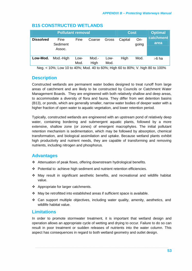
APPENDIX B – Protecting Waterways Manual
_____________________________________________________________________________________________________________________________________________________________________
53
B15 CONSTRUCTED WETLANDS Pollutant removal Cost Optimal
catchment area
Dissolved Fine Sediment
Assoc.
Fine Coarse Gross Capital On-going
Low-Mod. Mod.-High Low-Mod.
Mod.-High
Low-Mod.
High Mod. >6 ha
Neg. < 10%; Low 10 to 40%; Mod. 40 to 60%; High 60 to 80%; V. high 80 to 100% Description Constructed wetlands are permanent water bodies designed to treat runoff from large areas of catchment and are likely to be constructed by Councils or Catchment Water Management Boards. They are engineered with both relatively shallow and deep areas, to accommodate a diversity of flora and fauna. They differ from wet detention basins (B13), or ponds, which are generally smaller, narrow water bodies of deeper water with a higher fraction of open water to aquatic vegetation, and lower retention period. Typically, constructed wetlands are engineered with an upstream pond of relatively deep water, containing bordering and submergent aquatic plants, followed by a more extensive, shallow zone (or zones) of emergent macrophytes. The initial pollutant retention mechanism is sedimentation, which may be followed by absorption, chemical transformation, and biological assimilation and uptake. Because wetland plants exhibit high productivity and nutrient needs, they are capable of transforming and removing nutrients, including nitrogen and phosphorus. Advantages Attenuation of peak flows, offering downstream hydrological benefits.
Potential to achieve high sediment and nutrient retention efficiencies.
May result in significant aesthetic benefits, and recreational and wildlife habitat value.
Appropriate for larger catchments.
May be retrofitted into established areas if sufficient space is available.
Can support multiple objectives, including water quality, amenity, aesthetics, and wildlife habitat value.
Limitations In order to promote stormwater treatment, it is important that wetland design and operation allows an appropriate cycle of wetting and drying to occur. Failure to do so can result in poor treatment or sudden releases of nutrients into the water column. This aspect has consequences in regard to both wetland geometry and outlet design.

APPENDIX B – Protecting Waterways Manual
_____________________________________________________________________________________________________________________________________________________________________
54
The basin floor must have a relatively low hydraulic conductivity to prevent excessive infiltration and drying. The design residence time must be comparatively long. Consequently these systems require more land than other measures, such as wet detention basins. Mosquitoes may be a problem but can be minimised through appropriate design and operational activities.
Accompanying Measures Essential Appropriate inlet design (e.g. to achieve flow spreading, or otherwise reduce inflow
velocity) to minimise risk of sediment re-suspension within the basin.
Outlet design is critical to performance. Recent work suggests that weir and culvert outlets (both commonly used in constructed wetlands) have significant disadvantages compared with riser outlets (CRC for Catchment Hydrology, 1998).
An energy dissipater should be considered at the downstream end of the outlet pipe from the wetland.
Non-essential Wetlands may be provided with a two-stage outlet, facilitating storage up to the
design water quality event and a flood mitigation storm (e.g. a 100 year ARI event). Alternatively a high-flow bypass may be considered.
Planning and Design In order to meet the design objective of providing an efficient wetland pollutant management system, the following areas need to be addressed:
• location
• sizing
• maintenance
• multiple use
• morphology
• pre-treatment measures
• organic matter loading
• groundwater considerations
• outlet structures
• macrophyte planting
• safety
• mosquito control.
Location - is an important design consideration. Factors to be considered include adjacent land-uses, land availability and cost, desired aesthetics, habitat values, and water quality objectives. In hydrologic terms, wetlands must be protected from flood flows that can scour vegetation - this may entail the inclusion of a high-flow bypass.

APPENDIX B – Protecting Waterways Manual
_____________________________________________________________________________________________________________________________________________________________________
55
It is desirable, where practical, that wetlands located near creek systems be located off-line, with low flows directed to the wetland via a by-pass from the creek. In-line drainage can lead to a preferred drainage flow being along the (drowned) creek bed, resulting in reduced detention time and poorer treatment.
Where topographic constraints preclude provision of high-flow bypass, the wetland must be designed so that flow velocities during infrequent events (e.g. 100 year ARI) do not exceed 2 m/sec in order to minimise scouring vegetation. Under these flow conditions, it is likely that biofilms attached to wetland plants will be removed, although the plants themselves will help to minimise scouring, permitting recovery.
In areas where annual rainfall is low there may not be sufficient flow to maintain a permanent water body. In such circumstances, ephemeral wetlands may be more appropriate.
Pretreatment pond - pretreatment storage should be provided. An upstream sediment and litter trap is also recommended to avoid the difficulty and expense in removing accumulated sediment from the pre-treatment pond, and impact on aquatic life in the pond from excessive gross pollutants and sediment.
Design of the pretreatment pond should aim to maximise the effective hydraulic residence time through use of a uniform pond cross section, providing a long flow path (pond length : width of 3:1 to 10:1), and incorporating baffles, islands, rock walls or vegetation to reduce flow velocity and promote even flow distribution. Some form of energy dissipation is desirable at the inlet. Wind-induced erosion should be considered. A pond depth of 1.5 to 2 metres will reduce maintenance needs. For public safety, side slopes should be 8:1 or less (H:V) in unfenced areas and the gradient should be consistent above and below the water surface. Even grading of the banks will also minimise mosquito problems.
• Temporary flood storage - if necessary (e.g. if a high flow bypass is not feasible for the location), the pretreatment pond may incorporate temporary flood storage (e.g. up to 100 year ARI), the volume of which may be determined by a suitable rainfall-runoff model to meet the flood mitigation criteria.
• Temporary pond storage - (i.e. storage above permanent water in the pretreatment pond, but less than temporary flood-storage level) - can be incorporated into pretreatment to improve coarse particle retention during storm inflows, and to attenuate flows to the downstream wetland.
• The general function of a pretreatment pond is to trap sand-silt size particulates upstream of wetland areas. Ideally the size of permanent wet areas in the pretreatment zone will depend on particulate qualities, including settling velocity and mineralogy.
Wetland zone - wetlands should accommodate both shallow temporary and deeper permanent water storage zones:
• Temporary storage should be included to provide a variable wetting-drying cycle, which is important for wetland performance as it encourages a dense and diverse macrophyte growth and increases the area for enhanced filtration, sedimentation and biologic transformation.

APPENDIX B – Protecting Waterways Manual
_____________________________________________________________________________________________________________________________________________________________________
56
• The permanent deeper storage area is designed to encourage biofilm growth on macrophytes and additional sedimentation.
• Wetland sizing is influenced by factors such as the nature of the inflow, e.g. hydrology, chemistry and sediment particulate spectrum, and the geometry and planting scheme of the wetland. Principle considerations are the size of permanent and temporary storage of pretreatment pond and wetland areas. Discussion is provided in CRC for Catchment Hydrology, 1998. A ”rule of thumb” has been that wetlands require 1% to 2% of catchment area. Simple preliminary graphical sizing techniques to estimate the combined surface area (i.e. pond and wetland) to achieve particular pollutant removal rates have been developed. Graphs for TSS, TN and TP reduction are presented in Figure B15-1. For normal flows an area distribution of 30%:70% wetland (pond:wetland) is generally suitable, with increased wetland area appropriate if the inflow is high in dissolved or colloidal matter, or increased pond area if the inflow is coarser material.
• Drying substantially improves oxygen supply to sediments and results in relatively rapid organic decomposition, which is suitable for shallow marsh organic material regions to avoid accumulating organic material interfering with wetland hydraulic performance. A wet-dry cycle promotes development of a low-organic content, mineral sediment. On the other hand deep, oxygen-poor marsh zones promote slow organic decomposition which benefit pollutant treatment in that they act as long-term sinks of biodegradable material. However the cycle period will affect storage and availability of nutrients. For example phosphorus release is greatest from organic sediments after a medium duration inundation (e.g. 4 to 6 weeks), and least for mineral sediments under repeated short-duration inundation (less than 1 week). It is important to design and operate accordingly, allowing vegetation zones to fill and drain in response to the intermittent stormwater inflow.
• Where site constraints preclude provision of a high-flow bypass, the wetland must be designed so that flow velocities during infrequent events (e.g. 100 year ARI) do not exceed 2 m/sec to minimise scouring vegetation.
Wetland Morphology - Limit flow velocity to less than 0.2 m/sec and establish macrophyte zones perpendicular to the flow path. Vegetation depth zones generally should not exceed 0.6 m (generally comprising shallow marsh 0 to 0.2 m, marsh 0.2 to 0.4 m, deep marsh 0.4 to 0.6 m), with open water areas between these zones of 1.2 to 1.5 m depth to promote UV disinfection, and act as sediment sinks.
• Promote a wet-dry cycle across the wetland.
• Provide topsoil as a macrophyte substrate.
• Side slopes should be no steeper than 8:1 for safety.
• Grade bank evenly to minimise mosquito problems.
Wetland Outlet Structures - It is important to recognise that proper water depth variation, including wetting and drying, are necessary to regulate and maintain wetland vegetation and promote beneficial rather than detrimental, effects on the nutrient cycle. The ability to alter water depths is also important during vegetation planting and establishment and for maintenance operations (eg. weeding).

APPENDIX B – Protecting Waterways Manual
_____________________________________________________________________________________________________________________________________________________________________
57
The type and size of the outlet structure has a major impact on water level fluctuation. Preferred outlet structures are perforated riser outlets or siphon-type outlets, which should promote diverse vegetation and improved pollutant removal. Weirs and culverts are not suitable outlets as they achieve inappropriate water level fluctuation. The lowest holes in a perforated riser outlet should be located to create a permanent pool equal to 10 to 15% of the total storage volume. The outlet should incorporate manual control of water level and inundation duration to facilitate establishment of vegetation and management.
Macrophyte Planting- in the pond area is usually limited to pond edges and inlet area, if inflow velocity is sufficiently low. Macrophyte planting in the wetland system is extensive, and typically should extend across about 75% of the wetland area. This is graded into depth bands perpendicular to the flow. Generally the bands should not exceed 0.6 m (generally comprising shallow marsh 0 to 0.2 m, marsh 0.2 to 0.4 m, deep marsh 0.4 to 0.6 m), with the remaining 25% unplanted area being the open water 1.2 to 1.5 metres deep.
• Work scheduling must allow for potential long lead times for obtaining planting material. For information on planting design and site preparation, see construction considerations, below.

APPENDIX B – Protecting Waterways Manual
_____________________________________________________________________________________________________________________________________________________________________
58
Figure B15 - 1 Estimate of Key Pollutants Removal by a Constructed Wetland (adapted from CSIRO, 1999)
60
65
70
75
80
85
90
0% 1% 2% 3% 4% 5%
Wetland System Area (as % of catchment)
Susp
ende
d So
lids
Rete
ntio
n (%
)
010
2030
4050
6070
80
0% 1% 2% 3% 4% 5%
Wetland System Area (as % of catchment)
Tota
l Pho
spho
rus
Rete
ntio
n (%
)
010
2030
4050
6070
80
0% 1% 2% 3% 4% 5%
Wetland System Area (as % of catchment)
Tota
l Nitr
ogen
Ret
entio
n (%
)
Annual runoff 200 mmAnnual runoff 400 mmAnnual runoff 600 mm
Key :

APPENDIX B – Protecting Waterways Manual
_____________________________________________________________________________________________________________________________________________________________________
59
Construction Ensure that the levels of all components, in particular the outlet structure, are in
accordance with the design plan.
It is important that the system does not receive runoff until vegetation planting has taken place.
Preparation of a well prepared substratum which encourages plant growth and controls weed propagation is essential. Propagation of reeds will require approximately 0.2 m of topsoil. Soil should not be compacted, for example, by heavy machinery.
The outlet structure should be operated manually for such time as necessary to complete establishment of plantings.
Weed infestation, particularly along pre-existing drainage lines, can be a significant problem in establishing wetland plants. Weed control should be undertaken by physical or mechanical removal, or by herbicide use. If the latter practice is adopted, Glyphosate is a recommended herbicide, due to its ability to rapidly absorb to soil particles and fast decomposition. To maximise spraying effectiveness the site should be as dry as possible.
Plant sources include seeds, rhizomes, transplants, nursery material and soil cores from existing wetland areas. Seeding is only recommended for large sites. Generally, nursery propagated material is the preferred method for establishing vegetation. For additional information on advantages and disadvantages of each method, see CSIRO, 1999.
The advice of the Landscape Unit should be obtained for preparation of a revegetation plan and a suitable landscape contractor.
Maintenance Normal maintenance includes regular removal of sediment and litter from the pre-
treatment measure, removal of litter following storm events, and weed control. The frequency of sediment removal from the wetland zone may be expected to be 10 to 30 years where an adequate pretreatment zone has been provided. Drawing down the wetland water level will facilitate wetland maintenance. This may be achieved through an appropriate outlet structure design.
Plant harvesting to maintain the wetland's long-term nutrient retention capacity is unnecessary.
Inspections should be undertaken regularly, and performed as part of the maintenance program. Monitoring should include standardised reporting of the health and diversity of plants, detection and reporting of specific problem areas, including scouring, sediment, litter and oil accumulation, weed infestation, mosquito or other pest-associated problems and algae blooms. Because of potential for physical damage and the potential importation of weeds following large storms, inspection should take place after each major storm event.
Constructed wetlands are usually sized to meet specific outflow water quality targets, or a percentage pollutant(s) target removal.

APPENDIX B – Protecting Waterways Manual
_____________________________________________________________________________________________________________________________________________________________________
60
Appropriate data should be collected to determine whether or not the wetland is meeting any pre-set water quality objectives. In designing a monitoring regime for a particular site, it should be noted that a variety of factors can mask the actual efficacy of the wetland, including background wetland pollutant concentrations (e.g. turbulence re-suspending sediment, which has little relation to the inflow concentration).
References and Further Information • CSIRO (1999) Urban Stormwater: Best Practice Environmental Management
Guidelines. Prepared by the Stormwater Committee. Pub. CSIRO Publishing. ISBN 0 643 06453 2 (Appendix E).
• CRC for Catchment Hydrology (1998) Managing Urban Stormwater Using Constructed Wetlands- Industry Report. Cooperative Research Centre for Catchment Hydrology, Report 98/7.
• Urban Water Resources Centre, University of South Australia (1999) Workshop Notes on Source Control: Stormwater Management Design Procedures. Ed. J. R. Argue. (Chapter 10).
• Maryland Department of the Environment (2000) Maryland Stormwater Design Manual, Volumes I and II. Section 3.2.

APPENDIX B – Protecting Waterways Manual
_____________________________________________________________________________________________________________________________________________________________________
61
Figure B15 – 2 Typical In-stream Wetland Configuration (Source: NSW Dept. of Housing 1998)

APPENDIX B – Protecting Waterways Manual
________________________________________________________________________________________________________________________________________________________________________________
62
B16 OUTLET PROTECTION (Energy Dissipaters) Pollutant removal Cost Optimal
catchment area
Dissolved Fine Sediment
Assoc.
Fine Coarse Gross Capital On-going
Neg. Neg. * * Neg. Mod. Low NA
Neg. < 10%; Low 10 to 40%; Mod. 40 to 60%; High 60 to 80%; V. high 80 to 100% Description Energy dissipaters are used to reduce flow velocities and energy, thus minimising the risk of erosion near pipe outlets and reducing downstream sediment loads. This is particularly important in areas with highly erodible soils. Energy dissipaters absorb erosive energy by either obstructing the flow path, dissipating energy through creating a hydraulic jump into a stilling pool, or dispersing energy by spreading the water flow over a large area. There is a range of different designs suitable for a variety of situations.
Fan Apron Energy Dissipater These are widened flat, permanent structures constructed from rock (riprap, grouted riprap or gabions) located at pipe or culvert outlets. They spread the water in a fanning action over the rough, armored surface reducing the velocity and promoting sheet flow as the water exits into streams or onto vegetated areas.
Stilling pools These are basins which fill with water during runoff events which use the pooled water to dissipate the energy of the flowing water from the outlet structure. They can be formed as a basin with a bottom lower than the outlet channel or by constructing a weir across the outlet channel The basin is usually wider than the waterway and tapers to fit the existing channel at the basin exit point. Basins must always be lined with a non-erosive lining such as rock, earth or riprap underlain with a filter fabric or graded aggregate filter.
Drop Inlet box This is an enclosed structure, constructed or prefabricated from reinforced concrete, bricks, plastic or other sound structural material, which will receive the discharge from a pipe or culvert, dissipate the energy and safely release the runoff at a lower elevation. This structure is useful where there is a severe cross-slope from one side of the road to the other or a need to reduce drain slopes.
Level spreaders can be constructed out of any level, non-erodible material and generally used with lower flows.
Advantages Reduction in flow energy and velocity, leading to reduced scouring.
Generally easily installed.

APPENDIX B – Protecting Waterways Manual
________________________________________________________________________________________________________________________________________________________________________________
63
Accompanying Measures Essential Waterway protection will be required at appropriate downstream locations if the
stream bed or banks comprise easily erodible material and flow velocities cannot be adequately reduced to prevent scouring.
Planning and Design Energy dissipaters and outlet protection are high energy structures which must be
properly designed and installed. Many different designs have been used. Refer to appropriate reference material.
Construction Prepare the subgrade for riprap or gabions to the grade specifications. Compact any
subgrade fill to a similar density as the surrounding undisturbed material and protect the geofabric from damage by preparing a smooth, even foundation before traffic or machinery is allowed on the site.
Ensure the riprap or concrete used for energy dissipaters or outlet protection conforms to the grading limits specified on the works plan.
Place pervious geofabric between the subgrade and riprap to act as a soil and water filter. Ensure the geofabric has not sustained serious damage and repair any minor damage to the geotextile before spreading any aggregate.
Ensure that all joints overlap more than 300 mm.
Ensure that energy dissipaters such as riprap are continuous and can carry flow safely all the way to a stable outlet.
Maintenance Generally, well-designed and installed structures will not require maintenance.
Inspections should be undertaken following large storm events to ascertain whether damage has occurred.
References and Further information • NSW Department of Housing (1998) Managing Urban Stormwater: Soils and
Construction. ISBN 0731310969. Section 5.2.7.
• NSW Environment Protection Authority (1996) Managing Urban Stormwater - Construction Activities. Draft Report EPA 96/79. ISBN 0 7310 3809 6, pp 78-80. (Note: Outlet protection is described as a construction activity in the document. In the current Manual, they are listed as an operations-phase measure due to their permanency and performance capability for the longer term.

APPENDIX B – Protecting Waterways Manual
________________________________________________________________________________________________________________________________________________________________________________
64
Gabion energy dissipater at an outlet. Southern Expressway
Concrete energy dissipater. Southern Expressway

APPENDIX B – Protecting Waterways Manual
________________________________________________________________________________________________________________________________________________________________________________
65
Figure 16 – 1 Energy Dissipater (Source: NSW Dept. of Housing 1998)

APPENDIX B – Protecting Waterways Manual
_____________________________________________________________________________________________________________________________________________________________________
66
B17 WATERWAY AND BANK PROTECTION Pollutant removal Cost Optimal
catchment area
Dissolved Fine Sediment
Assoc.
Fine Coarse Gross Capital On-going
Neg. Neg. * * Neg. Mod. Low _
Neg. < 10%; Low 10 to 40%; Mod. 40 to 60%; High 60 to 80%; V. high 80 to 100% Description Waterway protection can reduce erosion and thus downstream sediment loads.
Channel Bed Stabilisation Measures Prior to the implementation of bank protection measures in watercourses (including drainage swales), it is important that the channel bed be stable. Appropriate measures to achieve this include:
Rock chutes: engineered structures designed to allow the bed to drop steeply over a short section without causing erosion. They can be used to stabilise existing erosion heads or to raise eroded bed levels upstream by trapping sediment behind the chute. They may be useful where significant drops in bed level exist, and where the bed is badly eroded.
Rock Riffles: Placement of selected rock across a prepared section of the creek. The height of a riffle is kept low so that they drown out at higher flows and do not cause local turbulence and scour. They are used to limit bed lowering or fix small erosion heads in watercourses or gullies.
Riffles - North American P300 matting: or similar is suitable to construct riffles for small dry or seasonally dry watercourses (gullies and possibly stormwater swales leading to creeks). The matting is used to construct an erosion resistant vegetated “cascade”, by wrapping soil in matting to form a series of 100 mm high drop weirs and 100 mm deep pools. The pools slow water and, by encouraging water retention, encourage gully revegetation.
Vegetative Stabilisation Measures Waterway protection of banks can also be achieved by providing vegetation protection. Vegetated waterways comprise shallow natural or constructed channels stabilised by suitable vegetation, to convey runoff safely downslope at a moderate, non-erosive velocity. Vegetated waterways can be constructed as an alternative to impermeable-lined systems, provided that an adequate root zone exists to maintain a healthy grass/vegetation cover, and the soils are not subject to lengthy inundation, waterlogging or trickle flow. They are suited to lower slopes and lower flow velocities.
In order to limit the degree of erosion occurring from banks (e.g. during any work requiring tree/woody plant removal or bank reworking), or from steep slopes, a staged

APPENDIX B – Protecting Waterways Manual
_____________________________________________________________________________________________________________________________________________________________________
67
plan of redevelopment is needed. This may entail banks or slopes being re-seeded with a temporary, protective grass species. Suitable species include annual ryecorn as it provides rapid soil cover whilst allowing other species (native grasses or reeds, as appropriate for the location) to grow in between and provide longer term cover, and Victorian perennial rye/dwarf tall fescue (50/50 mix) - possibly used with ryecorn to provide stabilisation prior to establishment of native species. Hydro-mulching (C10) is a method of soil stabilisation most effective for covering large, relatively difficult areas (e.g. steep banks), usually with grasses, although tree and shrub seeds may also be used. Use of temporary protective matting, such as "Enviromat", "Eco-mat", "Terra-mat" or "Jutemaster", which break down after one to two years (by which time protective vegetation should have established), may be considered for more vulnerable locations, such as steep slopes, outside of creek bends and at the toe of creek banks.
Armoured Stabilisation Measures Armoured waterways are natural or constructed water chutes, stabilised by means of natural or fabric armour such as permeable riprap or concrete, which are resistant to removal by very high water flow velocities. Armoured waterways should be used when there is insufficient room, or other unsuitable conditions to allow use of vegetative stabilisation. Where disposal of concentrated runoff at high velocities is necessary, it may be appropriate to use concrete or grouted riprap lined waterways.
Accompanying Measures Essential Energy dissipaters (B16) where necessary, to reduce velocity and flow energy.
Planning and Design Hydraulic procedures for estimating flow velocities, scour risk etc. should be in
accordance with methods provided in Australian Rainfall and Runoff, 1987.
It is important that waterway bed stabilisation occur before bank stabilisation measures are undertaken.
Vegetative waterways should, in general, be preferred to armoured waterways. Armoured waterways may be applicable where there is insufficient room, shallow soil or other unsuitable environmental conditions preventing the use of vegetated stabilisation.
Where possible the drainage line should be constructed in as natural a manner as possible to reinstate or maintain fauna habitats, and enhance the amenity of the area. Consideration should be given to native fish and fauna movement within the waterway (see Section 2.6 of this report).
Riprap or cemented gravel linings can withstand high velocities and may be suitable for use in critical sections of creeks (e.g. bends).
Construction Undertake construction activities in accordance with the works plan.

APPENDIX B – Protecting Waterways Manual
_____________________________________________________________________________________________________________________________________________________________________
68
Maintenance Maintenance of armoured structures should not be required. Armoured waterways
should be examined following periods of excessive rainfall to ensure they have not caused scouring of adjoining soil and are not blocked with debris.
Bed and vegetated areas should be inspected for signs of scour and sedimentation following high rainfall events.
References and Further Information • NSW Environment Protection Authority (1996) Managing Urban Stormwater -
Construction Activities. EPA 96/79. ISBN 0 7310 3809 6, pp. 66-69.
• NSW Department of Housing (1998) Managing Urban Stormwater: Soils and Construction. ISBN 0731310969. Section 5 and Appendix C.
Vegetative stabilisation measures – matting and grasses Panatalinga Road/Railway Terrace, Reynella
Nov 1995
Jan 1996
Feb 1996

APPENDIX B – Protecting Waterways Manual
_____________________________________________________________________________________________________________________________________________________________________
69
Armoured stabilisation measures – rock with vegetation. Adelaide/Crafers project
Rock chute
Where possible the drainage line should be constructed in as natural a manner as possible.
Gabion stabilised drainage line.
Rock and gabion stabilisation.

APPENDIX B – Protecting Waterways Manual
_________________________________________________________________________________________________________________________________________________________________________________
70
B18 STREET SWEEPING
Pollutant removal Cost Optimal catchment
area Dissolved Fine
Sediment Assoc.
Fine Coarse Gross Capital On-going
Neg. Neg. Neg. Low-Mod.
Mod. Mod. High _
Neg. < 10%; Low 10 to 40%; Mod. 40 to 60%; High 60 to 80%; V. high 80 to 100% *Note: The removals indicated above refer to current street sweeping technology and practices. General Description
Street sweeping collects sediment, debris, organic matter and litter off surfaces. The EPA Stormwater Pollution Prevention Code of Practice suggests the following timing of street sweeping: Residential streets at an interval not exceeding six weeks. Main and arterial roads where ribbon shopping is predominant at an interval not
exceeding three weeks. All other streets at an interval not exceeding eight weeks. Walker and Wong, 1999 discuss the effect of current street sweeping practices in Australia concluding that the effectiveness of street sweeping for pollutant removal is extremely limited. This is due in part to the poor removal of fine deposits by current street sweeping technologies, and because street sweeping is not undertaken often enough to remove build-ups of pollutants before storm events wash them from the road surface. To improve pollutant removal effectiveness, street sweeping requires:
New sweeping technologies that are more able to remove fine sediment. A potential technology is the small-micro surface sweeper recently under development in the USA, which may have greater capacity to pick up particulate matter.
Street sweeping at a frequency at least equal to the mean inter-rainfall event dry period. For Adelaide, this varies between 189 hours in February, to 44 hours in July.
Limiting roadside car parking during sweeping periods, as parked cars reduce the ability to properly sweep the road.

APPENDIX B – Protecting Waterways Manual
_________________________________________________________________________________________________________________________________________________________________________________
71
Advantages Removal of some coarse material, including litter, from road surfaces.
Improvement of road surfaces where skid resistance is affected.
Improves aesthetics.
Limitations Generally street sweeping will have negligible impact on removing fine sediment-
associated pollutants, such as heavy metals.
To be effective, street sweeping needs to be undertaken on a very regular basis.
Efficacy can be limited by kerbside parking.
Accompanying Measures None.
References and Further Information • Transport SA Master Specifications for the Maintenance of Roads. Maintenance
Activities Level 2(A). Section 3.10: Pavement Sweeping.
• Transport SA (1999) Road Maintenance Responsibilities (Section 26, Highways Act). Operational Instruction 20.1. Statewide Operational Coordination Group.
• Walker, T.A. & Wong, T.H.F., (1999) Effectiveness of Street Sweeping for Stormwater Pollution Control. CRC for Catchment Hydrology, Technical Report 99/8. ISBN 1 876006 47 1.
Street sweeping waste in Mt. Gambier