appendix d ion exchange plant design … exchange plant design operation and maintenance manual ......
TRANSCRIPT
Application for MMD Permit Revision and Modification of DP-61 Mt. Taylor Mine, April 2013
APPENDIX D
ION EXCHANGE PLANT DESIGN
Operation and Maintenance Manual
Plans


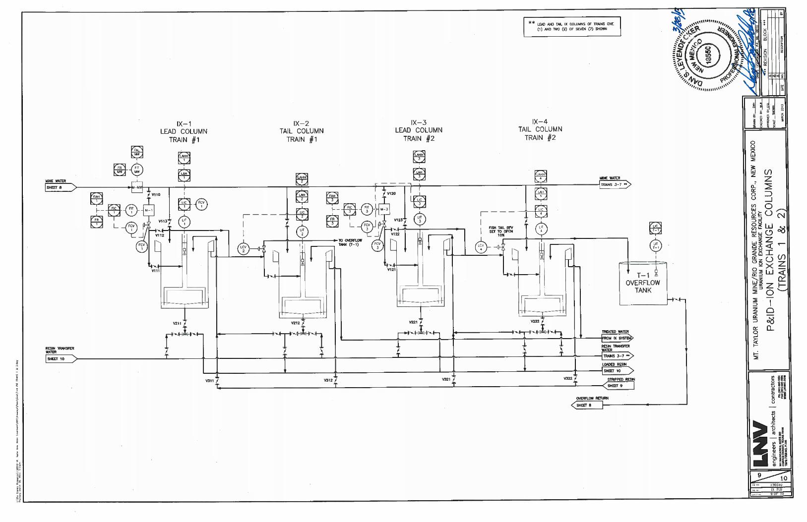


Table of Contents
I. Background Information ..................................................................................................... 1
II. Plant Function ..................................................................................................................... 2
III. Facility Description ............................................................................................................. 2
A. Mine Water Pumping ....................................................................................................... 2
B. Ion Exchange .................................................................................................................... 3
C. Resin Transfer .................................................................................................................. 3
D. Instrumentation................................................................................................................. 3
E. Plant Utility ...................................................................................................................... 4
F. Support Facilities ................................................................................................................. 4
IV. Plant Operation ................................................................................................................... 4
A. Mine Water Pumping ....................................................................................................... 4
B. Ion Exchange .................................................................................................................... 5
C. Resin Transfer .................................................................................................................. 6
D. Instrumentation................................................................................................................. 7
1. Mine Water Sump and Pumps ...................................................................................... 7
2. Lead IX Columns.......................................................................................................... 8
3. Tail IX Columns ........................................................................................................... 9
E. Quality Control of Discharge Fluids .............................................................................. 10
1. Sampling of Discharge Fluids .................................................................................... 10
2. Test Method ................................................................................................................ 10
Appendix A – Resin Spec Sheet

Page 1 of 10
MT. TAYLOR URANIUM IX PLANT OPERATING MANUAL
I. Background Information
Rio Grande Resources (RGR) plans to re-open the Mt. Taylor uranium mine located outside of
Grants, New Mexico. The existing mine has to be dewatered to enable access to the ore. To
dewater the existing mine works and operate the mine in the future, an extensive water
management system must be run in combination with a Mine Water Treatment Unit (MWTU) to
remove uranium (U) from the mine water to enable discharge to an NPDES-permitted outfall
north of the mine.
The water treatment will be operated in two main phases:
Phase 1 - Mine de-watering phase:
- Flow 8,000 -10,000 gallons per minute (gpm)
- U 0.07 parts per million (ppm) trend increasing
- TDS ~ 400 (ppm)
Phase 2 - Mine operation:
- Flow 4,000 -5,000 gpm
- U about 1 ppm (previous mining conditions, late phase)
- TDS 800 ppm
Discharge requirements:
- 30 parts per billion (ppb) U (human health standard in 20.6.2.3103.A(12)NMAC)
RGR considers U removal by ion exchange (IX) using the existing IX plant at the site as the
primary option. IX loaded resin will be transferred to an off-site facility, duly licensed by the
Nuclear Regulatory Commission (NRC) or an Agreement State, to be regenerated. The stripped
resin will then be returned for reuse at the IX Plant.
RGR has put together a uranium removal system utilizing a proven IX process to meet the
drinking water standard discharge requirements. The system will incorporate IX trains each
consisting of two IX columns in series. Each IX column will have a load capacity of 400 cubic
feet (ft3) of IX resin with a maximum loading capacity of 0.09 pounds of U per cubic foot of
resin. Each train has been designed to handle a maximum flow rate of 1,650 gpm and will be
operated at a nominal flow rate of 1,429 gpm. The individual trains will be sampled and assayed
to insure that the discharge water will not exceed the discharge limits for uranium of 30 ppb. The
IX columns are designed to transfer the resin in the lead IX column when it reaches a loading of
about 0.06 pounds of U per cubic foot, to prevent discharge exceeding 30 ppb U. The loaded
resin from the lead IX column will be transferred to one of two loaded resin storage tanks and
then will be off loaded to a resin tanker. The resin tanker will transport the loaded resin to an off-
site facility for regeneration.

Page 2 of 10
Each of the IX columns will be operated in an up flow mode with safeguards to prevent resin
leakage between IX columns or resin spills. Each of the IX columns will have safety devices to
prevent resin spills as follows: 1) resin screens in the overflow of each column, 2) a level control
system that will reduce the input flow rate to the lead IX column; and 3) a bypass on the tail
column to reroute bypass fluid to an overflow storage tank. The fluid sent to the overflow storage
tank will be recycled back to the main supply wet well where it will be fed to the lead IX
column.
II. Plant Function
The Mt. Taylor IX Plant is designed to treat 10,000 gpm of mine water for removal of uranium.
The ion exchange process for recovering uranium from mine water utilizes a quaternary amine
incorporated onto a porous styrene divinylbenzene bead. The amine has the ability to give up
anions in exchange for anions in solution, in this case,' uranium. When loaded with uranium to
0.06 pounds U per cubic foot the resin will be transported to an offsite facility to be regenerated
with a concentrated brine solution in a split elution cycle. The regenerated resin will be returned
to Mt. Taylor to be reused.
The following drawings should be referred to in conjunction with this Operation and
Maintenance Manual (O&MM):
Drawing No. Description
2 Symbols & Legend (Sheet 1 of 2)
3 Symbols & Legend (Sheet 2 of 2)
4 Equipment Layout Plan
5 Foundation Containment Plan
6 Miscellaneous Details
7 Process Flow Diagram
8 P&ID - Mine Water Wet Well
9 P&ID - IX Columns (Trains 1 & 2)
10 P&ID - Resin Storage and Transfer
III. Facility Description
Refer to Drawing Number 4 - Equipment Layout Plan for the location of the various items
described below. The Mt. Taylor IX Plant consists of five mine water pumps, four operating and
a spare, seven IX trains with two IX columns each (14 columns total), two loaded resin storage
columns, one overflow storage tank and two resin transfer water storage tanks. All of the above
equipment except the mine water pumps are enclosed within the building. Also housed inside of
the building are the motor control center (MCC), office, control room and restroom.
A. Mine Water Pumping
Mine Water gravity flows from the treatment lagoons to a wet well located
adjacent to the IX building on the south side. The wet well has dimensions of 30

Page 3 of 10
ft. x 6 ft. x 8 ft. 4 in. deep. The mine water wet well is covered by a platform
which supports the five mine water transfer pumps (MWP-1, 2, 3, 4, and 5). Each
mine water pump has a capacity of 2,500 gpm. For the plants’ capacity of 10,000
gpm, four pumps are operating with one full spare.
B. Ion Exchange
The IX portion of the facility is located within the building and consists of seven
trains of two IX columns each (14 columns total). Each train has a capacity of
1,650 gpm or one-sixth the total plants flow. The IX trains are arranged so that
water will gravity flow from the first (lead) column (IX-1, 3, 5, 7, 9, 11, and 13)
in each train to the second (tail) column (IX-2, 4, 6, 8, 10, 12, and 14). Water
from the tail column in each train will then gravity flow to the plant discharge.
Each column is provided with overflow screens to prevent resin loss. Each
column has a diameter of 12 ft with a 12 ft straight sidewall, and is loaded with
approximately 400 ft3 of resin.
C. Resin Transfer
The resin transfer system consists of two resin transfer water storage tanks (T-
2A/2B), a single process water pump (P-2), and two loaded resin storage tanks (T-
3A/3B). The resin is transferred as a slurry with water and will incorporate the
use of eductors at each vessel. Eductors are a type of device that uses liquid
pressure as a motive force to effectively convey granular solids or slurries over
relatively short distances. The eductors are supplied with process water from a
200 gpm centrifugal pump which is sufficiently sized for transferring resin from
one vessel at a time.
Once the resin has been loaded with uranium in the IX columns, the resin from a
given column will first be transferred to one of two loaded resin storage tanks,
each capable of holding 1,000 ft3 of resin. The purpose of the loaded resin
storage tank is to temporarily hold loaded resin while it awaits transport to the
offsite facility for regeneration. The loaded resin will then be transferred to a resin
tanker that can hold up to 1,500 ft3 of resin. This resin tanker will transport the
loaded resin to the regeneration facility and then return regenerated resin back to
Mt. Taylor to be put back into service.
Facilities are provided for hydraulic transport of the resin between the IX
columns, loaded resin storage tanks, and resin tanker. To reduce water
consumption, water used to transport resin throughout the facility will be recycled
and stored in the resin transfer water storage tanks.
D. Instrumentation
The control system that RGR proposes to install in the IX Plant will be a
computer-based system. It will incorporate an active screen for each process and
will display real time activities of tank levels and process flow rates. This system
will have input from flow transmitters and level transmitters. The IX system will

Page 4 of 10
be monitored by operators and a Programmable Logic Controller (PLC) located in
the control room.
E. Plant Utility
The following utility services are provided at the IX Facility: electricity, potable
water, process water and instrument air. A 13.8 KV line delivers primary power
from the Mt. Taylor Mine to a transformer for conversion to 440/220 volts.
Distribution to plant users is through the MCC. Potable water is delivered to the
IX Facility through an underground line originating at the Barium Chloride
Building. Process water is provided at appropriate locations at a pressure of 60
pounds per square inch (psi). Filtered and dried instrument air is supplied by a
23.5 actual cubic feet per minute (ACFM) compressor at 100 psi for operation of
pneumatic controls.
F. Support Facilities
Forced air heating is provided for the entire IX building. The office, MCC and
restroom are air conditioned.
IV. Plant Operation
A. Mine Water Pumping
Refer to Drawing 8 - P&ID - Mine Water Wet Well
1) The mine water wet well is equipped with an inlet line from the mine
water ponds and a bypass line that can in emergency situations feed excess
water to the radium removal system.
2) Under normal operations Valves V901 and V902 are fully open and the
Isolation Valve V903 is closed.
3) The mine water pumping system is designed so that four of the five mine
water transfer pumps will provide the necessary capacity. The fifth pump
provides backup capacity.
4) Before starting the mine water pumps, the operator should select the
desired wet well level for the level indicator controller (LIC located in the
control room).
5) Two IX trains will be valved open to accept mine water flow and one mine
water pump will be turned on. The operator will adjust fluid flow through
both IX trains prior to placing a second pump and any additional trains in

Page 5 of 10
service. This procedure will be followed until the desired water flow is
obtained.
6) The mine water wet well is provided with level control which will
automatically maintain a constant level within the wet well. This is
accomplished through the use of Variable Frequency Drive (VFD) on each
mine water pump (MWP-1, MWP-2, MWP-3, MWP-4 and MWP-5). The
level controller is set at a predetermined elevation that will adjust the VFD
accordingly to maintain this level set point. The level device will be
installed in the wet well to cover the operating level range. In the event
that the level continues to increase, the operator must manually reduce the
incoming fluid to the mine water wet well. If the level drops below the
low-low setting, the pumps will sequentially turn off to protect the pumps
from insufficient fluid level.
7) To shut off the flow of water to the IX Plant, the following sequence
should be observed:
Open Valve V903
Close Valves V901 & V902
The IX Plant will now be bypassed and all mine water will flow from the
settling ponds to the Barium Chloride Treatment Facility.
8) To initiate flow of mine water to the IX Plant, the following sequence
should be observed:
If Closed, Open Valves V901 & V902
Close Valve V903
The operator should visually observe the water levels in the mine water
wet well at the IX Plant to insure that no obstructions are impeding the
flow of water.
B. Ion Exchange
Refer to Drawing 9 - P&ID - IX Columns (Trains 1 & 2)
The IX Plant will utilize seven identical trains. Each train will have a capacity of
1,650 gpm and will consist of two (2) 12-foot diameter columns in each train. The
operation of one train is described below as an example. The components and
functions will be identical for the remaining trains.
Feed water is delivered by the mine water transfer pumps to the main plant
header. This 24-inch diameter header is located above the IX columns. A mag

Page 6 of 10
meter (M-MW) is located in the header with a flow recorder (FR-MW) and low
flow alarm (FAL-MW) is located in the control room.
Prior to initiating flow to the IX columns, the operator should check the resin
drain Valves V211 and V212, located below the IX column tank, to insure that
they are both closed. Valves V112 and LCV-2 should be closed. Valve V110
should now be opened. The flow control valve (FCV-1) will regulate the flow to
the IX train.
To begin flow to the Lead IX column, open Valve V110, check to make sure
V112 and LCV-2 are closed and set FCV-1 to 25 percent of desired flow rate.
Check the resin depth in the column and make sure flow has been established
throughout train number one. Repeat this on train number 2 and then start
increasing the flow rate through both trains by adjusting the VFD on the mine
water pump and FCV to the desired flow rate.
The IX trains are designed with the capability of bypassing both the lead and tail
IX columns. The FCV or LCV (LCV for tail column and FCV for lead column)
will maintain a constant level in the IX column by opening and closing depending
on observed levels and flow rates. If the LCV or FCV fails and the level
increases past the first set point the operator will be notified by the level alarm
high (LAH). In the event that the LCV still cannot control the flow, the level will
continue to increase to the second set point. At this point, the operators will place
the spare IX train in service which will receive flow diverted from the upset IX
column. If the spare train is not ready to receive flow, the level alarm high high
will sound and the bypass valve will open automatically. This will divert flow
from the upset Tail IX column to the overflow storage tank.
C. Resin Transfer
Refer to Drawing 7 - Process Flow Diagram
Refer to Drawing 9 - P&ID - IX Columns (Trains 1 & 2)
Refer to Drawing 10 - P&ID - Resin Storage and Transfer
When the resin in the lead column of an IX train is loaded to about 0.06
pounds/ft3 with uranium, a resin transfer cycle will begin and proceed in the
following order.
1. The resin will first be transferred from the lead IX column to the loaded-
resin storage tanks.
2. The partially loaded resin from the tail IX column will then be transferred
to the lead IX column.
3. Stripped (regenerated) resin will be transferred from the resin tanker to
refill the tail IX column.
4. Loaded resin will be transferred from a loaded resin storage tank to the
resin tanker.

Page 7 of 10
The loaded resin will be removed from the lead IX column(s) (IX-1, 3, 5, 7, 9, 11,
13) by an eductor, where it is fluidized by the resin transfer water and conveyed
through a 4” steel pipe at 200 gpm to the loaded resin storage columns. The
transfer lines between each IX column have a clear inline sight glass so that the
operator can determine when all of the resin has been removed. The inline sight
glass will also allow the operator to ensure that the resin is in fact moving out of
the IX column. The loaded resin storage columns (T-3A and T-3B) are located in
the northeast quadrant of the building and are 8 ft in diameter by 20 ft high. The
resin transfer water pump (P-2) will provide water from the resin transfer water
storage tanks (T-2A and T-2B) at the necessary flow rate and pressure to fluidize
the resin and transport it through the resin transfer cycle.
The partially loaded resin will then be removed from the tail IX column by an
eductor and hydraulically transported to the lead IX column. This process will
begin immediately after the loaded resin has been removed from the lead IX
column.
The regenerated ion exchange resin will be transferred hydraulically from the
resin tanker to the tail IX column(s) (IX-2, 4, 6, 8, 10, 12, or 14). This process
will begin immediately after the partially loaded resin has been removed from the
tail IX column, and transferred to the lead IX column.
The loaded resin will then be transferred from either T-3A or T-3B to the resin
tanker. The resin transfer volume from the loaded resin storage tanks to the resin
tanker is determined by the level indicator controller. The operator will open the
resin tanker compartment hatch and drop the resin transfer hose into the
designated receiving compartment. Once this is complete, the resin transfer water
pump (P-2) and the resin outlet valve for either of the resin storage tanks will
open. The “resin out” valve will close when the level indicator controller reaches
a predetermined level change equal to 400 ft3. Excess water drained from the
resin tanker during the resin transfer process will be picked up by a sump (SP-1),
and pumped through a filter (F-1, F-2, or F-3) prior to being sent back to resin
transfer water storage tanks (T-2A or T-2B). The reason for filtering and
recycling is to minimize water consumption. The hose connection from the
tanker to the resin eductor will have a “no-spill” check valve and a clear sight
glass. The purpose of the sight glass will be to provide the operator with a view
of the media being transferred, enabling the operator to determine when all of the
resin has been transferred. The no-spill check valve will prevent water and/or
resin from spilling during connection and disconnection.
D. Instrumentation
1. Mine Water Sump and Pumps
Mine Water Transfer Pumps will have local start-stop switches with a stop
only switch located in the control room. In the event of low level in the
mine water sump, the level indicator controller (LIC-MW) will adjust the
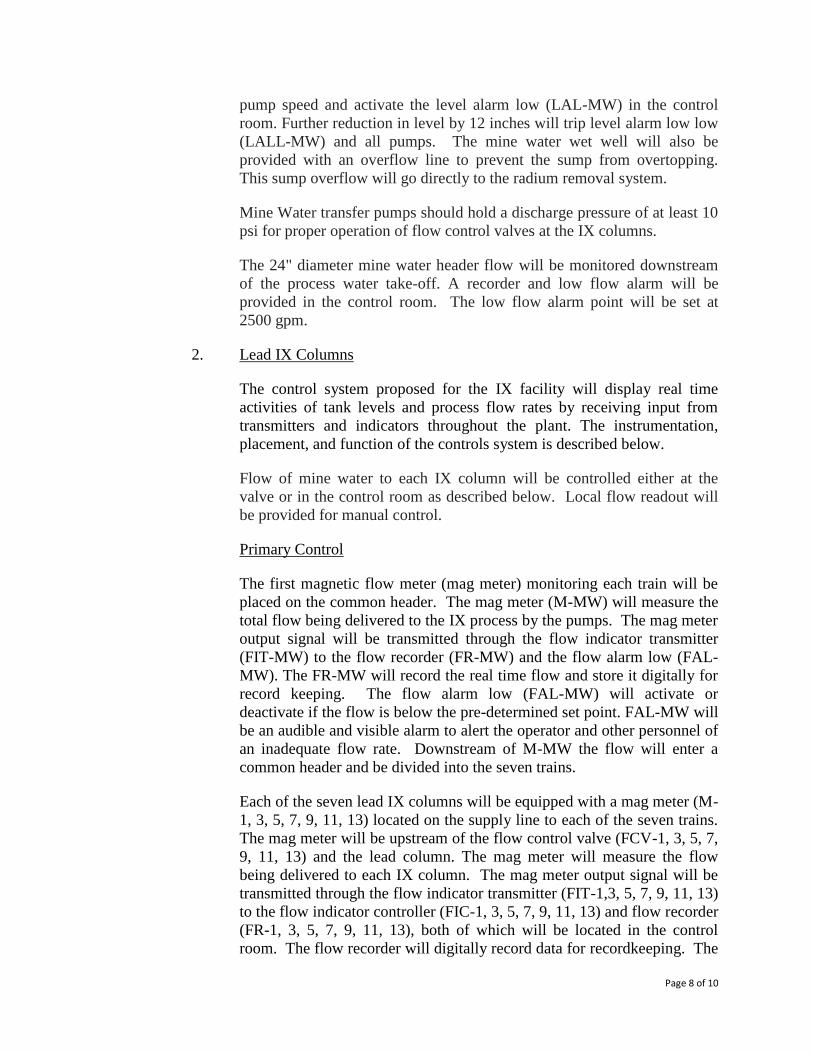
Page 8 of 10
pump speed and activate the level alarm low (LAL-MW) in the control
room. Further reduction in level by 12 inches will trip level alarm low low
(LALL-MW) and all pumps. The mine water wet well will also be
provided with an overflow line to prevent the sump from overtopping.
This sump overflow will go directly to the radium removal system.
Mine Water transfer pumps should hold a discharge pressure of at least 10
psi for proper operation of flow control valves at the IX columns.
The 24" diameter mine water header flow will be monitored downstream
of the process water take-off. A recorder and low flow alarm will be
provided in the control room. The low flow alarm point will be set at
2500 gpm.
2. Lead IX Columns
The control system proposed for the IX facility will display real time
activities of tank levels and process flow rates by receiving input from
transmitters and indicators throughout the plant. The instrumentation,
placement, and function of the controls system is described below.
Flow of mine water to each IX column will be controlled either at the
valve or in the control room as described below. Local flow readout will
be provided for manual control.
Primary Control
The first magnetic flow meter (mag meter) monitoring each train will be
placed on the common header. The mag meter (M-MW) will measure the
total flow being delivered to the IX process by the pumps. The mag meter
output signal will be transmitted through the flow indicator transmitter
(FIT-MW) to the flow recorder (FR-MW) and the flow alarm low (FAL-
MW). The FR-MW will record the real time flow and store it digitally for
record keeping. The flow alarm low (FAL-MW) will activate or
deactivate if the flow is below the pre-determined set point. FAL-MW will
be an audible and visible alarm to alert the operator and other personnel of
an inadequate flow rate. Downstream of M-MW the flow will enter a
common header and be divided into the seven trains.
Each of the seven lead IX columns will be equipped with a mag meter (M-
1, 3, 5, 7, 9, 11, 13) located on the supply line to each of the seven trains.
The mag meter will be upstream of the flow control valve (FCV-1, 3, 5, 7,
9, 11, 13) and the lead column. The mag meter will measure the flow
being delivered to each IX column. The mag meter output signal will be
transmitted through the flow indicator transmitter (FIT-1,3, 5, 7, 9, 11, 13)
to the flow indicator controller (FIC-1, 3, 5, 7, 9, 11, 13) and flow recorder
(FR-1, 3, 5, 7, 9, 11, 13), both of which will be located in the control
room. The flow recorder will digitally record data for recordkeeping. The

Page 9 of 10
flow indicator controller will be programmable so that the operator can set
it to maintain a desired flow rate. The flow indicator controller will send a
signal to a flow control valve which will open and close to maintain the
desired flow rate set on the flow indicator controller. The flow indicator
controller will also activate or deactivate the flow alarm high (FAH-1, 3,
5, 7, 9, 11, 13). The flow alarm high will be an audible and visible alarm
whose set point can be determined and programmed by the operator.
Secondary Control
Each of the seven lead IX columns will be equipped with a sonic level
sensor, located in the column tank, which will send its output signal to a
level indicator transmitter (LIT-1, 3, 5, 7, 9, 11, 13). The level indicator
transmitter will transmit a signal to the level indicator controller (LIC-1, 3,
5, 7, 9, 11, 13). The level indicator controller will be located in the control
room and display the water level in each lead column in real time. The
level indicator controller will also be programmable to maintain a certain
set point level. The purpose of the level indicator controller is to monitor
tank levels and to insure that the levels are not high enough to overtop the
tanks and cause a spill. The level indicator controller will communicate to
the lead column flow control valve (FCV-1, 3, 5, 7, 9, 11, 13), the level
alarm high (LAH-1, 3, 5, 7, 9, 11, 13), and the level alarm high high
(LAHH-1, 3, 5, 7, 9, 11, 13). In the event that the first level set point has
been reached the level indicator controller will activate the level alarm
high to notify the operator. The level indicator controller will also adjust
the flow control valve appropriately to maintain the programmed set point
and prevent a spill. In the event that the level indicator controller is not
able to resolve the abnormally high water level by manipulating the flow
control valve and the second set point is reached, the level indicator
controller will activate the level alarm high high and the operator will be
able to manually divert the entire flow around the high level column to the
tail IX column. The tail IX columns will have the ability to divert excess
flow from the lead IX columns to the overflow storage tank (T-1).
3. Tail IX Columns
Each of the seven tail IX columns will be equipped with a sonic level
sensor, located in the column tank, which will send its output signal to a
level indicator transmitter (LIT-2, 4, 6, 8, 10, 12, 14). The level indicator
transmitter will transmit a signal to the level indicator controller (LIC-2, 4,
6, 8, 10, 12, 14). The level indicator controller will be located in the
control room and display the water level in each tail column in real time.
The level indicator controller will also be programmable to maintain a
certain set point level. The purpose of the level indicator controller is to
monitor tank levels and to insure that the levels are not high enough to
overtop the tanks and cause a spill. The level indicator controller will
communicate to the tail column level control valve (LCV-2, 4, 6, 8, 10,

Page 10 of 10
12, 14), the level alarm high (LAH-2, 4, 6, 8, 10, 12, 14), and the level
alarm high high (LAHH-2, 4, 6, 8, 10, 12, 14). In the event that the first
level set point has been reached the level indicator controller will activate
the level alarm high to notify the operator, the level indicator controller
will also adjust the level control valve appropriately to maintain the
programmed set point and prevent a spill. In the event that the level
indicator controller is not able to resolve the abnormally high water level
by manipulating the level control valve and the second set point is
reached, the level indicator controller will activate the level alarm high
high. When the level alarm high high is activated the level control valve
will be closed 100% and all flow to the tail IX column will be diverted to
the overflow storage tank (T-1).
E. Quality Control of Discharge Fluids
1. Sampling of Discharge Fluids
a. Composite sampling will be performed for all IX Tail columns, total
discharge stream of the IX system and the total discharge stream leaving
the facility.
b. This composite sampling will be on an eight (8) hour schedule and will
incorporate a duplicate sample bottle for third party assay.
c. The operator will grab samples every eight (8) hours from each lead and
tail IX column to determine when resin transfer must occur to keep the
system discharge stream below the 30 ppb standard for uranium.
2. Test Method
a. The test method for uranium will follow the ASTM D5174 Standard.
This test method for trace uranium in water uses Pulsed-Laser
Phosphorimetery analyzed by a KPA (Kinetic Phosphorescence
Analyzer). This analyzer achieves highly specific analysis for uranium
down to 0.01 μg/L with an analytical range of over 500,000 μg/L.
b. The third party assay laboratory will be a NELAC-certified laboratory
that will use a KPA system or other method(s) with detection
capabilities sufficient to reliably detect down to 0.01 μg/L.

APPENDIX A

Product Information
Page 1 of 2 * Trademark of The Dow Chemical Company Form No. 177-01892-1005 DOWEX Ion Exchange Resins
DOWEX 21K 16/20 A High Efficiency, Large Bead, Strong Base Anion Exchange Resin for Mineral Processing Applications
Product Type Matrix Functional group DOWEX* 21K 16/20 Type I strong base anion Styrene-DVB, gel Quaternary amine Guaranteed Sales Specifications Cl- form Total exchange capacity, min. eq/L 1.2 Bead size distribution Thru 20 mesh, max. Thru 25 mesh, max.
% %
10 2
Typical Physical and Chemical Properties Cl- form Water content % 50 - 58 Whole uncracked beads % 90 - 100 Total swelling (Cl- ⇒ OH-) % 20 Particle density g/mL 1.08 Shipping weight g/L
lbs/ft3 690 43
Recommended Operating Conditions
• Maximum operating temperature: OH- form Cl- form
• pH range • Bed depth, min. • Flow rates:
Service/fast rinse Backwash Co-current regeneration/displacement rinse
• Total rinse requirement • Regenerant:
Type Temperature
• Organic loading, max.
60°C (140°F) 1 00°C (212°F) 0 - 14 8 00 mm (2.6 ft) 5 - 50 m/h (2 - 20 gpm/ft2) See figure 1 1 - 10 m/h (0.4 - 4 gpm/ft2) 3 - 6 Bed volumes NaCl/Carbonate Ambient or up to 50°C (122°F) or silica removal f 3g KMnO4/l resin

Typical properties and applications
DOWEX 21K 16/20 type I strong base anion resin has excellent kinetics, excellent regeneration efficiency and outstanding physical stability. This enhanced-porosity gel bead product is made by a special process giving enhanced resistance to organics and fast equilibrium rates. The DOWEX 21K family of resins is specially suited for mineral processing and groundwater remediation applications. DOWEX 21K 16/20 type I strong base resin is suited for fluidized-bed and Resin-in-Pulp applications.
Packaging 5 cubic foot fiber drums
Figure 1. Pressure Drop vs. Flow Rate For DOWEX 21K Resins, Cl, 77 deg. F
Pre
ssu
re D
rop
(psi
/ft
Res
in)
Flow (gpm/ft2)
21K XLT
Page 2 of 2 *Trademark of The Dow Chemical Company Form No. 177-01892-1005
21K 16/3021K 16/20
8
7
6
5
4
3
2
1
00 10 20 30 40 50 60
21K 16/20
21K XLT
21K 16/30
Figure 2. Backwash Expansion vs. Flow Rate For DOWEX 21K Resins, Cl, 77 deg. F
Bac
kwas
h E
xpan
sio
n(%
exp
ansi
on
)
Flow (gpm/ft2)
21K XLT21K 16/3021K 16/20
120
100
80
60
40
20
00 2 4 6 8 10
DOWEX Ion Exchange Resins For more information about DOWEX resins, call the Dow Liquid Separations business: North America: 1-800-447-4369 Latin America: (+55) 11-5188-9222 Europe: (+32) 3-450-2240 Pacific: +60 3 7958 3392 Japan: +813 5460 2100 China: +86 21 2301 9000 http://www.dowex.com
Warning: Oxidizing agents such as nitric acid attack organic ion exchange resins under certain conditions. This could lead to anything from slight resin degradation to a violent exothermic reaction (explosion). Before using strong oxidizing agents, consult sources knowledgeable in handling such materials. Notice: No freedom from any patent owned by Seller or others is to be inferred. Because use conditions and applicable laws may differ from one location to another and may change with time, Customer is responsible for determining whether products and the information in this document are appropriate for Customer’s use and for ensuring that Customer’s workplace and disposal practices are in compliance with applicable laws and other governmental enactments. Seller assumes no obligation or liability for the information in this document. NO WARRANTIES ARE GIVEN; ALL IMPLIED WARRANTIES OF MERCHANTABILITY OR FITNESS FOR A PARTICULAR PURPOSE ARE EXPRESSLY EXCLUDED.