appendix d: solar radiation - university...
TRANSCRIPT

D - 1
APPENDIX D: SOLAR RADIATION
The sun is the source of most energy on the earth and is a primary factor in determining the
thermal environment of a locality. It is important for engineers to have a working knowledge
of the earth's relationship to the sun. They should be able to make estimates of solar radiation
intensity and know how to make simple solar radiation measurements. They should also
understand the thermal effects of solar radiation and know how to control or utilize them.
The earth is nearly spherical with a diameter of about 7,900 miles (12.7 x 10³ km). It makes
one rotation about its axis every 24 hours and completes a revolution about the sun in a period
of approximately 365 1/4 days. The earth revolves around the sun in a nearly circular path,
with the sun located slightly off center of the circle. The earth's mean distance to the sun is
about 9.3 x 10⁷ miles (1.5 x 10⁸ km). Around January 1, the earth is closest to the sun while
on around July 1 it is most remote, about 3.3% farther away. Since the intensity of solar
radiation incident upon the top of the atmosphere varies inversely with the square of the earth-
sun distance, the earth receives about seven per cent more radiation in January than in July.
The earth's axis of rotation is tilted 23.5 degrees with respect to its orbit about the sun. The
earth's tilted position is of profound significance. Together with the earth's daily rotation and
yearly revolution, it accounts for the distribution of solar radiation over the earth's surface, the
changing length of hours of daylight and darkness, and the changing of the seasons.
Figure 1 shows the effect of the earth's tilted axis at various times of the year. Figure 2 shows
the position of the earth relative to the sun's rays at the time of winter solstice. At the winter
solstice (around December 22), the North Pole is inclined 23.5 degrees away from the sun. All
points on the earth's surface north of 66.5 degrees north latitude are in total darkness while all
regions within 23.5 degrees of the South Pole receive continuous sunlight. At the time of the
summer solstice (around June 22), the situation is reversed. At the times of the two equinoxes
(around March 22 and September 22), both poles are equidistant from the sun and all points on
the earth's surface have 12 hours of daylight and 12 hours of darkness.

D - 2
BASIC EARTH-SUN ANGLES
The position of a point P on the earth's surface with respect to the sun's rays is known at any
instant if the latitude, l, and hour angle, h, for the point, and the sun's declination angle,
d, are known. Figure 3 shows these fundamental angles. Point P represents a location on the
northern hemisphere.
Figure 1: The earth's revolution about the sun
Figure 2: Position of the earth in relation to the sun's rays at time of winter solstice

D - 3
Figure 3: Latitude, hour angle, and sun's declination angle
The latitude, l, is the angular distance of the point P north (or south) of the equator. It is the
angle between the line OP and the projection of OP on the equatorial plane. Point O
represents the center of the earth. The calculation of the various solar angles, performed later
in this chapter, can be simplified by the adoption of a consistent sign convention. As part of
this sign convention, north latitudes are positive and south latitudes are negative.
The hour angle, h, is the angle measured in the earth's equatorial plane between the projection
of OP and the projection of a line from the center of the sun to the center of the earth. At solar
noon, the hour angle is zero. The hour angle expresses the time of day with respect to solar
noon. One hour of time is represented by 1524360 =÷ degrees of hour angle. As part of the
convention, the hour angle is negative before solar noon and positive after solar noon.
The sun's declination angle, d, is the angular distance of a sun's rays north (or south) of the
equator. It is the angle between a line extending from the center of the sun to the center of the
earth and the projection of this line upon the earth's equatorial plane. The declination is
positive when the sun's rays are north of the equator and negative when they are south of the
equator. At the time of the winter solstice, the sun's rays are 23.5 degrees south of the earth's
equator (d = -23.5°). At the time of the summer solstice, the sun's rays are 23.5 degrees north
of the earth's equator (d = 23.5°). At the equinoxes, the sun's declination is zero.
The declination angle throughout the year can be well approximated by a sine function:

D - 4
( ⎥⎦⎤
⎢⎣⎡ += nd 284365360sin45.23 ) [degrees] Equation 1
where n is the day of the year. The value of n for any day of the month "D" can be determined
easily with the aid of Table 1.
Table 1: Variation in "n" throughout the year for use in Equation 1
RELATIONSHIP BETWEEN CLOCK TIME AND SOLAR TIME
Solar radiation calculations must be made in terms of solar time. In a discussion of time,
numerous designations may be used. We will consider here only a brief description to allow us
to convert local clock time to solar time for engineering calculations.
Time reckoned from midnight at the Greenwich meridian (zero longitude) is known as
Greenwich Civil Time or Universal Time. Such time is expressed on an hour scale from zero
to 24. Thus, midnight is Oh and noon is 12h. Local Civil Time is reckoned from the precise
longitude of the observer. On any particular meridian, Local Civil Time is more advanced at
the same instant than on any meridian further west and less advanced than on any meridian
further east. The difference amounts to 1/15 hour (4 minutes) of time for each degree
difference in longitude.
At a given locality, clock time generally differs from civil time. Clocks are usually set for the
same reading throughout an entire zone covering about 15 degrees of longitude. The United
States is divided into four time zones. The time kept in each zone is the Local Civil Time of a
selected meridian near the center of the zone. Such time is called Standard Time. The four
standard meridians in the United States are at west longitudes of 75 degrees (Eastern Standard
Time, EST), 90 degrees (Central Standard Time, CST), 105 degrees (Mountain Standard Time,
MST), and 120 degrees (Pacific Standard Time, PST). In many localities, clocks are advanced

D - 5
one hour beyond Standard Time in summer. In the United States, such time is called Daylight
Savings Time.
Time as measured by the apparent diurnal motion of the sun is called Apparent Solar Time,
Local Solar Time, or Solar Time. Whereas a civil day is precisely 24 hours, a solar day is
slightly different due to irregularities of the earth's rotation, obliquity of the earth's orbit and
other factors. The difference between Local Solar Time, LST and Local Civil Time, LCT is
called the Equation of
Time, E.
The factors described above can be included into a single equation, which relates solar time and
clock time:
LST = CT +1
15⎛ ⎝ ⎜ ⎞
⎠ ⎟ Lstd − Lloc( )+ E − DT [hr] Equation 2
Where:
LST = Local Solar Time [hr]
CT = Clock Time [hr]
Lstd = Standard Meridian for the local time zone [degrees west]
Lloc = Longitude of actual location [degrees west]
E = Equation of Time [hr]
DT = Daylight Savings Time correction (DT = 0 if not on Daylight Savings Time,
otherwise DT is equal to the number of hours that the time is advanced for Daylight
Savings Time, usually 1hr)
In using Equation 2, all of the times must first be converted to decimal format from zero to 24,
(e.g., a clock time of 3:45 p.m. is expressed as CT = 15.75 hr).
Values of the Equation of Time, E, are calculated by:
BBBE sin025.0cos126.02sin165.0 −−= [hr] Equation 3a
D - 6
where: B =360 n − 81( )
364 [degrees] Equation 3b
and n is the day of the year.
Once Local Solar Time is established, the solar hour angle, h can be calculated. By recalling
that the hour angle varies at the rate of 15 degrees per hour, that h = 0 at solar noon, and that
the sign convention is h < 0 before solar noon, the equation for the hour angle is determined by:
( 1215 −= LSTh ) [degrees] Equation 4
DERIVED SOLAR ANGLES
Besides the three basic angles (latitude, hour angle, and sun's declination), several other angles
are useful in solar radiation calculations. Such angles include the sun's zenith angle θH,
altitude angle β, and azimuth angle φ. For a particular surface orientation, the sun's incidence
angle θ, and surface-solar azimuth angle γ, may be defined. All of these additional angles may
be expressed in terms of the three basic angles.
To an observer on the earth, the sun appears to move across the sky following the path of a
circular arc from horizon to horizon. Figure 4 schematically shows one apparent solar path and
defines the sun's zenith, altitude, and azimuth angles. Point P represents the position of the
observer, point O is the center of the earth, and IDN is a vector representing the sun's rays. The
zenith angle θH is the angle between the sun's rays and local vertical, i.e. a line perpendicular to
the horizontal plane at P. The altitude angle β is the angle in a vertical plane between the sun's
rays and the projection of the sun's rays on the horizontal plane. It follows that β + θH = π/2 =
90O. The azimuth angle φ is the angle in the horizontal plane measured from south to the
horizontal projection of the sun's rays.

D - 7
Figure 4: Definition of sun's zenith, altitude, and azimuth angles
Thus the following equations can be derived:
cosθ H = cos l cosh cosd + sin l sin d Equation 5a
Since Hθβ −= 90 , [degrees] Equation 5b
sinβ = cosl cosh cosd + sin lsin d Equation 6
The sun's azimuth, φ, is given by the relation:
cosφ =1
cosβcosd sin l cos h − sind cosl( ) Equation 7
The sign convention used for the azimuth angle, φ, is negative east of south and positive west
of south. Notice that this sign convention results in the hour angle, h, and the sun's azimuth
angle, φ, always having the same sign. Since the cosine is an even function, calculating the
right hand side of Equation 7 and taking the inverse cosine will not provide the information
needed for the sign convention. The user must assign the appropriate sign.
Equations 5 - 7 allow calculation of the sun's zenith, altitude and azimuth angles if the
declination, hour angle, and latitude are known. In applying these equations, attention must be
given to correct signs. A summary of the sign convention is:

D - 8
l: north latitudes are positive, south latitudes are negative
d: the declination is positive when the sun's rays are north of the equator, i.e. for the
summer period in the northern hemisphere, March 22 to September 22 approximately,
and negative when the sun's rays are south of the equator.
h: the hour angle is negative before solar noon and positive after solar noon
φ: the sun's azimuth angle is negative east of south and positive west of south
In calculations involving other than horizontal surfaces, it is convenient to express the sun's
position relative to the surface in terms of the incidence angle, θ. The sun's angle of incidence
is the angle between the solar rays and the surface normal. (Notice that for a horizontal
surface, the surface normal is the local vertical and the incidence angle is equal to the zenith
angle, θH.)
In order to evaluate the angle of incidence we need to specify the direction of the surface
normal. This is done in terms of the surface tilt angle, Σ, and the surface azimuth angle, Ψ.
These angles are defined in Figure 5. The surface tilt angle is the angle between the surface
normal and vertical. The surface azimuth angle is the angle between south and the horizontal
projection of the surface normal. The same sign convention is used for the surface azimuth
angle as is used for the solar azimuth angle, i.e. Ψ is negative for a surface that faces east of
south and positive for a surface that faces west of south. The azimuth angle for a horizontal
surface is undefined.
Figure 5: Definitions of surface azimuth, surface tilt, and surface-solar azimuth angles and the
relation of the sun's rays to a tilted surface

D - 9
It is convenient to define one additional angle, the surface-solar azimuth angle, γ. As shown
in Figure 5, the surface-solar azimuth angle is defined as the angle between the horizontal
projection of the solar rays and the horizontal projection of the surface normal. Examination of
Figure 5 reveals that as long as one adheres to the sign conventions for the azimuth angles φ
and Ψ, the surface-solar azimuth angle is given by the simple relation:
γ = φ − Ψ( ) [degrees] Equation 8
In Figure 5, for the tilted surface:
cosθ = cosβ cosγ sin Σ + sinβ cosΣ Equation 9
If the surface is vertical (Σ=90°), then:
cosθ = cosβ cosγ Equation 10
If the surface is horizontal (Σ=0), then:
cosθ = sinβ = cosθ H Equation 11
Thus, as previously described, it is seen that the incidence angle for a horizontal surface is
equal to the zenith angle.
ESTIMATION OF INTENSITY OF SOLAR RADIATION DURING AVERAGE
CLEAR DAYS
In order to predict the solar contributions to building cooling loads it is desirable to estimate
the solar intensity on typical or average clear days. An estimate of the direct normal solar flux
at the earth's surface for an average clear day is:
IDN = Ae−B sinβ Equation 12
where the coefficients A and B are empirically determined from measurements of IDN made on
typical clear days. The coefficients can be interpreted as:
A = Apparent direct normal solar flux at the outer edge of the earth's atmosphere
B = Apparent atmospheric extinction coefficient

D - 10
The numerical values of A and B vary throughout the year because of seasonal changes in the
dust and water vapor content of the atmosphere and because of the changing earth-sun distance.
The ASHRAE Handbook of Fundamentals lists recommended values for the coefficients A and
B for the twenty-first day of each month. These values are presented in Table 2. Also included
in the table are the values of the declination angle and Equation of Time that ASHRAE lists in
conjunction with the clear day coefficients. These values are for the base year 1964. A
comparison of the declination angles listed for 1964 and those predicted by Equation 1 reveals
that they are in good agreement. Similarly, the calculated values for the Equation of Time agree
to within 0.01 hour with those for the 1964 base year. Thus, for the purpose of making HVAC
calculations the approximations of Equations 1 and 3 provide acceptable values for the
declination angle and Equation of Time.
Table 2: Coefficients for average clear day solar radiation calculations for the twenty-first day of each month, base year 1964 The use of Equation 12 with the coefficients presented in Table 2 is commonly referred to as
the ASHRAE Clear Day Solar Flux Model. The model also approximates the average clear
day diffuse solar flux from the sky that strikes a horizontal surface, IdH, by the relation:
IdH = CIDN Equation 13
The recommended values of the dimensionless coefficient C are listed in Table 2.

D - 11
The ASHRAE Clear Day model does not give the maximum values for IDN that can occur
during the month, but rather are representative of conditions on average, cloudless days. For
very clear atmospheres, ASHRAE points out that values of IDN can be 15% higher than those
calculated using Equation 12 and Table 2.
SOLAR RADIATION STRIKING A SURFACE
The solar radiation striking a surface generally consists of three components, direct, diffuse
and reflected. The direct, or beam, solar radiation is that received from the sun without having
been scattered by the atmosphere. The direct solar flux (energy/area-time) striking a surface is
denoted by ID. If the surface is perpendicular to the solar rays, the incident solar flux is equal to
the Direct Normal flux, IDN. From Figure 5 it can be seen that if the solar flux strikes a surface
at an angle of incidence θ, the direct solar flux striking the surface is given by:
ID = IDN cosθ Equation 14
In the case of a horizontal surface, an additional subscript, H, is used. Thus, IDH is the direct
solar flux striking the horizontal. Notice that for a horizontal surface the incidence angle is
equal to the zenith angle, θH, and therefore:
IDH = IDN cosθ H = IDN sinβ Equation 15
The diffuse solar radiation is that received from the sun after its direction has been changed by
scattering by the atmosphere. The diffuse solar flux striking a surface is denoted by Id for the
general case and by IdH for the special case of a horizontal surface. Diffuse radiation is
typically of rather short wavelength, since short-wavelength radiation is scattered more by the
atmosphere. Although diffuse solar radiation on clear days is usually small compared to direct
radiation, it cannot be ignored in engineering calculations. During extremely cloudy days, only
diffuse solar radiation may reach the ground. Because of its non-directional nature, diffuse
solar radiation is more difficult to analyze than direct solar radiation, consequently less is
known about it. A common approximation is that the sky is a uniform radiator of diffuse
radiation. Assuming the sky to be a diffuse source, the ratio of the diffuse solar flux striking
the surface to that striking the horizontal is given by:

D - 12
Id
IdH
= 1+ cos Σ( 2) Equation 16
The reflected solar radiation is that which strikes a surface after the radiation is reflected from
surrounding surfaces. In general, the solar radiation reflected upon a surface depends on the
particular location, orientation and solar reflectance characteristics of the surrounding surfaces.
One commonly occurring situation is where the solar radiation is reflected from the ground.
If the ground is horizontal and if the reflection is diffuse, an approximation for the reflected
solar flux striking a surface, IR, is given by:
IR = ρgIH 1− cos Σ( 2) Equation 17
where:
ρg = solar reflectance of the ground
IH = Total solar flux striking the horizontal ground
The reflectance of the ground varies with the type of ground cover. The reflectance of browned
grass is about 0.2, while that of bare soil is about 0.1. The reflectance of fresh snow cover may
be as high as 0.87, with the value decreasing to less than 0.5 as the snow becomes dirty.
The total solar flux striking a surface at any instant is the sum of the three components:
I = ID + Id + IR Equation 18
Notice that if any two of the solar flux values that appear in the above set of equations are
known, either by prediction or measurement, the rest of the quantities can be evaluated. In
the case of the use of the ASHRAE Clear Day model, the quantities IDN and IdH are predicted
using Equations 12 and 13 respectively, along with the coefficients presented in Table 2.
SOLAR RADIATION MEASUREMENT
Experimental determination of the energy transferred to a surface by solar radiation requires
instruments that will measure the heating effect of direct solar radiation and diffuse solar
radiation. There are two general classes of solar radiation measuring devices. The instrument
D - 13
used to measure direct normal or beam radiation is referred to as a pyrheliometer. The other
instrument, called a pyranometer, is able to measure total radiation within its hemispherical
field of view. A pyranometer can also be used to measure diffuse radiation alone by shading
the sensing element from the sun’s direct rays.
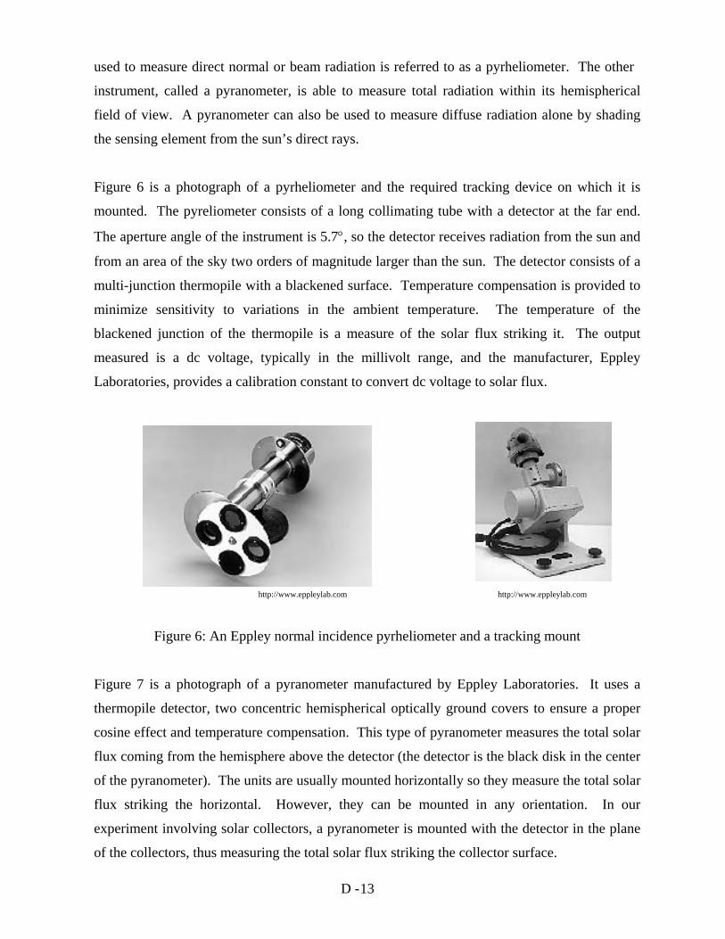
Figure 6 is a photograph of a pyrheliometer and the required tracking device on which it is
mounted. The pyreliometer consists of a long collimating tube with a detector at the far end.
The aperture angle of the instrument is 5.7°, so the detector receives radiation from the sun and
from an area of the sky two orders of magnitude larger than the sun. The detector consists of a
multi-junction thermopile with a blackened surface. Temperature compensation is provided to
minimize sensitivity to variations in the ambient temperature. The temperature of the
blackened junction of the thermopile is a measure of the solar flux striking it. The output
measured is a dc voltage, typically in the millivolt range, and the manufacturer, Eppley
Laboratories, provides a calibration constant to convert dc voltage to solar flux.
http://www.eppleylab.com http://www.eppleylab.com
Figure 6: An Eppley normal incidence pyrheliometer and a tracking mount
Figure 7 is a photograph of a pyranometer manufactured by Eppley Laboratories. It uses a
thermopile detector, two concentric hemispherical optically ground covers to ensure a proper
cosine effect and temperature compensation. This type of pyranometer measures the total solar
flux coming from the hemisphere above the detector (the detector is the black disk in the center
of the pyranometer). The units are usually mounted horizontally so they measure the total solar
flux striking the horizontal. However, they can be mounted in any orientation. In our
experiment involving solar collectors, a pyranometer is mounted with the detector in the plane
of the collectors, thus measuring the total solar flux striking the collector surface.

D - 14
http://www.eppleylab.com
Figure 7: An Eppley Precision pyranometer
A pyranometer can be fitted with a shading ring to block the beam or direct solar radiation. In
this case, the device measures approximately the diffuse plus reflected solar flux from the
hemisphere above the detector. Figure 8 is a photograph of a pyranometer with a shading ring.
The design of the ring allows continuous recording of the diffuse plus reflected flux throughout
the day. The position of the ring is adjusted for the changing declination angle only and can be
done every few days.
http://www.eppleylab.com
Figure 8: Pyranometer with shading ring to eliminate direct solar radiation