appendix f: monitoring and control of the iot...
TRANSCRIPT

Appendix F: Monitoring and Control of the IoT Network F-1
Appendix F: Monitoring and Control of the IoT Network Contents Abstract ......................................................................................................................................................... 3
1 Introduction .......................................................................................................................................... 3
1.1 Appendix Organization.................................................................................................................. 4
2 Central Management Tools................................................................................................................... 4
2.1 Overview ....................................................................................................................................... 4
2.2 Vendor Platforms .......................................................................................................................... 6
2.2.1 Ubiquiti AirControl2 .............................................................................................................. 6
2.2.2 Axis Camera Management Client .......................................................................................... 7
2.2.3 HikVision iVMS-4200 Client ................................................................................................... 7
2.2.4 Panasonic ASM200 Operation Software ............................................................................... 8
2.3 Tools and Service Used in Central Management Prototypes ....................................................... 9
2.3.1 MongoDB .............................................................................................................................. 9
2.3.2 Microsoft Azure IoT Hub ..................................................................................................... 10
2.3.3 Node.js ................................................................................................................................ 10
2.3.4 Electron ............................................................................................................................... 10
3 Local Implementation Specifics .......................................................................................................... 10
3.1 Storage Server ............................................................................................................................. 10
3.2 Device Connection ...................................................................................................................... 11
3.3 Device Management ................................................................................................................... 11
3.3.1 Management Server ........................................................................................................... 11
3.3.2 Device Status Monitoring .................................................................................................... 11
3.3.3 Wi-Fi Radios ........................................................................................................................ 12
3.3.4 IP Cameras .......................................................................................................................... 12
3.3.5 Adapters .............................................................................................................................. 13
3.3.6 UHF RFID ............................................................................................................................. 13
3.3.7 Radars ................................................................................................................................. 13

Appendix F: Monitoring and Control of the IoT Network F-2
3.4 Graphical User Interface ............................................................................................................. 14
4 Cloud Implementation Specifics ......................................................................................................... 15
4.1 Storage Server ............................................................................................................................. 15
4.2 Device Connection ...................................................................................................................... 16
4.3 Device Management ................................................................................................................... 16
4.3.1 Management Server ........................................................................................................... 16
5 Results/Effectiveness/Problems/Limitations/Solutions ........................ Error! Bookmark not defined.
5.1 Management Server/ Azure IoT Hub Troubles .............................. Error! Bookmark not defined.
5.2 Wi-Fi Radios ................................................................................... Error! Bookmark not defined.
5.3 Cameras ......................................................................................... Error! Bookmark not defined.
5.4 Adapters ......................................................................................... Error! Bookmark not defined.
6 Guidelines ........................................................................................................................................... 16
7 Conclusions ......................................................................................................................................... 17
8 References .......................................................................................................................................... 18

Appendix F: Monitoring and Control of the IoT Network F-3
Abstract This appendix details work pertaining to creating a central management control system for an IoT smart
city. Various vendor management platforms for currently deployed devices are presented to show the
functionalities that they exhibit and the lack of full-city device management centralization.
Implementation solutions and specifics are explained, as well as the major issues in development including
a significant lack in management standardization. Conclusions highlight effective management protocol
methods found such as SSH and how a different network structure could change the central management
strategy.
Appendix F: Monitoring and Control of the IoT Network F-4
1 Introduction In an IoT smart city there will be an enormous number of devices that need to be monitored and maintained. Manually monitoring each device individually in a mature smart city would simply be impossible. It would require too much manpower and reaction-time to errors would be much too slow. A stable central management platform is necessary to automate elementary monitoring such as whether a device is connected, if it is transmitting an appropriate amount of data, or whether it’s battery levels are low. For a smart city to work efficiently a robust hierarchical alert and automatic reconfiguration system must be in place. The problem of central management becomes difficult when one considers the number of elements that must be involved in the platform. The platform must be capable of monitoring devices connected to the network through various mediums and protocols, and must be capable of translating information for a device regardless of manufacturer or device type. This problem must be eased by a standardization of IoT protocols in the future. Although many IoT platforms are commercially available, significant effort will still be required to configure and test them with multi-vendor, multi-communication type IoT devices, some of the platforms might focus on certain communication interface type (for example based on cellular network, like CISCO-Jasper or Ericsson IoT Accelerator), or certain data type (for example: streaming high BW video devices or small BW but massive amount of sensors like garbage can, or car parking detector). As a result, a flexible, adaptable and customizable centralized device management structure is one of the most important components in a Smart City setup to prevent service/device provider lock-in. This appendix will discuss existing platforms, development, implementation issues, and recommendations in developing a scalable central management platform for future engineers.
1.1 Appendix Organization This following appendix sections are organized as follows. First, an overview of central management goals and deployed vendor central management tools will be detailed. Next, the tools used in the development of a prototype smart city will be described, followed by implementation specifics for both local and cloud-based applications. Subsequently, guidelines are presented along with conclusions.
2 Central Management Tools 2.1 Overview The deployed physical network structure contains various types of devices, many of them produced by different manufacturers. Some of these devices, such as the Wi-Fi radios and IP cameras, have specially developed central management software. Some vendors provide these software platforms free of charge, while others require a subscription charge or product purchase. Vendor-made central management software from Ubiquiti, Axis, HikVision, and Panasonic were tried throughout the deployment. Each software is only capable of managing devices from its own product line and type, and the features differ greatly from vendor to vendor. Some software focuses more on an overview control to alert users of product failures or warnings, while others focus more on creating one console for viewing many device settings. A prototype platform capable of monitoring all deployed devices from one location was developed after examination of commercial options. The goal was to develop software capable of rebooting devices and check whether they were online on the network. Throughout the design process, the use of standard protocols was emphasized to highlight inter-vendor capabilities. The central management platform prototype has a graphical user interface capable of rebooting and network status monitoring of devices in addition to its API capabilities.

Appendix F: Monitoring and Control of the IoT Network F-5
The platform can be rolled out in two ways, via pure local private connection or connected to the public cloud via Azure IoT Hub and MongoDB Atlas. The exact same control backend runs regardless of implementation, just with a local database replaced with a cloud database. Rather than the platform connecting through Azure IoT Hub, the private solution directly contacts the management server. The cloud-connected prototype platform makes use of two large cloud services: Microsoft Azure IoT Hub, and MongoDB Atlas. Azure IoT Hub is used as a communication bridge between deployed devices and the central platform to enable command and data transfer. MongoDB Atlas is a cloud database storage center which is used to store device related information. More on these two cloud services and uses will be discussed in subsequent sections.
Figure 1: Diagram of cloud-based central management data flow
The abstracted system is composed of four fundamental parts: a device, device gateway, database, user connection, and user interface. These parts can be found highlighted in pink in Figure 1 above. In the local implementation, each of the parts except for the device is integrated within a management server. The server acts as a gateway to the device, has a local database for device information, runs the user interface, and connects the user interface to the device gateway. A command such as reboot dispatches from the user interface, through the user connection to the device gateway. Database is queried for authentication information and the command is sent to the device. The device responds with a success or failure, and the device is highlighted in blue.

Appendix F: Monitoring and Control of the IoT Network F-6
2.2 Vendor Platforms This section will discuss commercial vendor software and features available for use in the Montreal deployment.
2.2.1 Ubiquiti AirControl2 Ubiquiti AirControl2 is a free graphical user interface platform capable of monitoring Ubiquiti’s Wi-Fi radios. It is possible to create automated alerts, configure select devices, and view relevant radio information such as online status, signal strength, throughput [1]. A screenshot of the user interface can be seen in Figure 2.
Figure 2: Ubiquiti AirControl2 graphical user interface
AirControl2 development does not appear to be a priority as it greatly lags their hardware improvements. While AirControl2 can configure M5 series radios in batch directly within the console, it does not support this same feature for the full AC generation or the recently released AC2 generation. Note, a new beta was just released during this writing which provides management support to two AC devices.

Appendix F: Monitoring and Control of the IoT Network F-7
2.2.2 Axis Camera Management Client
Figure 3: Axis Camera Management Client
Axis Camera Management provides basic camera monitoring and management features. Through its graphical user interface software, it is possible to view camera online status, view and set alarms, and create configuration restore points [2]. It does not allow for mass firmware upgrade. Figure 3 presents what the client looks like.
2.2.3 HikVision iVMS-4200 Client The iVMS-4200 software client is the central management tool developed for HikVision cameras. It has features that enable online status monitoring, camera configuration, alarm setup, and event management for programmed events [3]. Mass firmware update is not supported. The device management page can be seen below in Figure 4.

Appendix F: Monitoring and Control of the IoT Network F-8
Figure 4: HikVision iVMS-4200 Client
2.2.4 Panasonic ASM200 Operation Software Panasonic offers a purchasable management tool for its cameras: ASM200 software. This software allows users to adjust camera settings in terms of viewing and recording parameters. Camera feeds can be viewed within the console. It also provides alarm, device, and network error logging [4]. Firmware upgrade is not a supported feature. Figure 5 is a screen capture of the interface.

Appendix F: Monitoring and Control of the IoT Network F-9
Figure 5: Panasonic ASM200 Operation Software
2.3 Tools and Service Used in Central Management Prototypes This section will provide high level information regarding Azure IoT Hub, MongoDB database, and the development tools used to create the software API and graphical user interface. Additionally, this section will strive to present a basic understanding of how each tool relates or is implemented into the management platform.
2.3.1 MongoDB
MongoDB is a document-oriented NoSQL database. The hierarchy structure of a MongoDB database is as follows. A database stores a number of collections. Each collection can be described as a folder which holds documents. Documents in a collection do not need to store the same information fields and are stored as BSON files. For the central control platform, the database contains a collection full of relevant device information such as type and authentication. The database is queried to maintain full up to date device lists.
Figure 6: Diagram showing what the database is used for

Appendix F: Monitoring and Control of the IoT Network F-10
2.3.2 Microsoft Azure IoT Hub Microsoft Azure IoT Hub is a cloud-based solution to connecting devices. It establishes bi-directional communication between its central storage hub and a device. Devices can communicate between each other by sending commands to the IoT Hub central location with the recipient device name. The hub then routes the information on to the proper device destination [5]. Communication is conducted via messaging format, where SSL encrypted payloads are sent between devices. Messaging protocols natively supported are MQTT, AMQP, and HTTP. Devices are connected via connection strings. The central hub and each device has its own unique URL string. Devices attach themselves to the hub by use of their own unique URL connection string to start listening for messages. To send a command to another device, devices use the central hub’s connection string and designate the name of the device to which the information should be sent [5]. Devices connecting to the Azure IoT Hub can be authenticated in two ways: symmetric key or X.509 certificate. X.509 security certificate is much more secure, but requires that the IoT Hub generated X.509 certificate be placed in the physical device. This ensures that only that specific device can connect to its accompanying connection string [5]. Microsoft provides several SDKs to work with including C, Node.js, and Java. The SDKs allow developers to begin integrating the IoT Hub into their solutions quickly [5]. IoT Hub was used as the connection medium to connect the central management platform to devices on the smart city network in the deployed cloud-based central management prototype. The platform sends commands to the central hub with the proper device destination. The message is sent through the IoT Hub, the command executed, and a success or failure status code message returned.
2.3.3 Node.js Node.js is the language that was used to develop the central management backend. It is a language that leverages the syntax of JavaScript with an asynchronous, non-blocking nature for running server applications. Node.js has a large package management service npm, where many open source packages and libraries can be found [6]. These packages were used to maintain productivity and test IoT management feasibility rather than focusing time on writing code to create http connections or send pings.
2.3.4 Electron The graphical interface for the central management platform is designed using the Electron framework. This framework allows the creation of applications using web development technologies. HTML, CSS, and JavaScript libraries and frameworks can be used to generate an application window [7]. To create the central management platform graphical user interface prototype, HTML, CSS, native JavaScript, and JQuery were used.
3 Local Implementation Specifics This section details the central management platform implementation with keeping every element within the private network.
3.1 Storage Server MongoDB was selected for information storage to maximize time efficiency as it was a familiar system and can be deployed locally or in the cloud. For efficient information storage, the organization of the MongoDB database was set up as follows. A cluster called ‘bcrl-central-management’ was created in a management server on the IoT server subnet. Inside this cluster, a collection named ‘devices’ was generated. This collection was designed to store the device information of each device on the network.

Appendix F: Monitoring and Control of the IoT Network F-11
For each device in the ‘devices’ collection, there are seven data fields: ip_address, div_id, type, company, user, pass, url. The field ip_address is used to hold the ip address at which a device can be found. Div_id also stores the ip_address except for with each dot in the ip_string replaced by an underscore for ease in environments such as JavaScript where a dot signifies a special character. Device descriptions such as S2E for serial to Ethernet devices, or ip_camera for cameras are set within the type field. Company, user, and pass denote the manufacturer and the authentication credentials for the device. For optional integration to a cloud integration system, the URL field stores the device’s Azure connection string.
Figure 7: Diagram showing the device information fields and relation to collection and cluster
The ‘devices’ collection can be upgraded to include more descriptive fields, but for prototyping and proof-of-concept, these seven fields were sufficient.
3.2 User Connection User connection is the term used here to describe the ability to connect the central management user interface to deployed devices or to a device gateway. In the local setup, the user interface runs on the management platform. As the server is also a device gateway, it is its own direct user connection.
3.3 Device Management Integration of various parts of the central management are discussed within this section. This section includes management setup, how management services are performed, and reasoning. It provides insight to developing software capable of rebooting devices, as well as encountered issues.
3.3.1 Management Server In the local implementation, the management server is the server which in running the central management platform. It is a computer within the network which has network access to each of the devices.
3.3.2 Device Status Monitoring Monitoring of device online status is accomplished through sending ICMP ping packets from the management server to the IP device. The ping test is scheduled and performed every 20 seconds to maintain an active status log. This test is performed on Wi-Fi radios, IP cameras, and Serial-to-Ethernet adapters. Two log files are kept, one for rebooting devices, and one for offline devices. If a device is not in either of these logs, then it is known it must be online. The logs are formatted into comma-separated-value (csv) files. Each time an online status check (ping test) is performed, if a device does not return a ping response, an entry with the time, date, and IP address will be added to the rebooting or offline log file, depending

Appendix F: Monitoring and Control of the IoT Network F-12
on whether a reboot command was recently sent or not. Each new line specifies a new entry. This allows a user to import the data into an excel spreadsheet to manipulate data or parse based on values separated by commas and new lines.
Figure 8: Screenshot of several entries from csv offline log file
3.3.3 Managing of Stationary Devices This section provides details how deployed devices on the static network could be rebooted.
3.3.3.1 Wi-Fi Radios
The Ubiquiti Wi-Fi radios deployed in the physical network have Telnet and SSH capabilities. Due to SSH’s encrypted communication method, SSH was used to manage radios. The radios’ SSH client can perform reboots, speed tests, return hardware statistics and information. To perform a reboot, the management server waits for a signal from the management platform. When the management server receives a reboot command, it creates an SSH connection to the radio using the ‘ssh2’ npm package. The ssh connection can be fulfilled using username:password authentication taken from the MongoDB database or via the use of RSA keys. The deployed Ubiquiti Wi-Fi radios were easily rebootable and controllable through SSH connection. For further management functionalities with more detailed data, such as data relating to current maximum throughput available, custom calculations based off relevant data must be performed.
3.3.3.2 IP Cameras
All the IP cameras deployed in the small-scale prototype smart city network in downtown Montreal have ONVIF protocol capabilities. ONVIF is a standard which was developed to maintain same management and camera control commands across any camera that is compatible. The use of ONVIF allows development of one method to perform a function, rather than many using vendor-specific APIs.
The reboot ONVIF command is sent to the cameras via an https connection created through the Node.js npm ‘request’ library.
Cameras authenticate the username and password credentials before receiving the command. Most vendors use basic authentication, but Axis uses digest authentication. To make sure the authentication passes, the proper authentication technique must be performed. In the central management prototype platform, the Node.js ‘request’ has an option that enables various authentication schemes to be
Figure 9: ONVIF command to perform reboot from the ONVIF Application Programmers Guide [1]

Appendix F: Monitoring and Control of the IoT Network F-13
attempted. This option makes it possible for one method to perform commands on any device without writing separate code for each authentication scheme. By using the ONVIF standard, development time for implementing camera functions into a central management platform can be greatly reduced. This is a result of not having to worry about any specific manufacturer APIs or function calls. While developing software that ran ONVIF commands on cameras from different vendors, there were sometimes issues relating to the underlying software on the cameras themselves. Cameras from different manufacturers had different parsers. This sometimes resulted in a poorly formatted ONVIF command being properly parsed and executed by one camera, but resulted in an error for another. Thus, before software is rolled into deployment, it is imperative to test that the command can be executed and read by all camera vendors.
3.3.3.3 Adapters
In the physical network, adapters are used to transform signals between communication protocols, such as from Ethernet to Serial. Some devices, such as traffic radars, are not connected via an IP addressing scheme, and are accessed via socket ports on an adapter. This includes traffic radars and RFID readers. Unfortunately, there does not exist a standardized command scheme to manage or control adapter devices. Vendors offer different methods of restarting their devices. USR IOT devices can be restarted via their webserver or UDP broadcast, Perle and Lantronix devices can be restarted via webserver, SSH, or other options. Reboot of adapters was more difficult to implement than for other devices, and functioning integration to the management platform was not successful. There was difficulty in automating reboot of Perle and Lantronix adapters due to SSH response to reboot command with expected keyboard confirmation. Two Node.js SSH libraries were used to try and solve this problem, but they were not successful. Through development of a more robust, specific-case SSH Node.js package, it would be possible to implement, but that is beyond the scope of this feasibility test. Reset of the USR IOT devices was attempted via the UDP broadcast method, but was not successful. Because the management server exists on a different subnet and the gateway between them did not enable UDP broadcasting between different subnets, the signal could not reach the USR IOT devices. Experimentation was also conducted to try and automate through the USR IOT webserver restart, but it appears like an autoclick mechanism would need to be created.
3.3.3.4 UHF RFID
To restart the RFID reader, the reset [0x64] command must be dispatched to the reader. This can be accomplished through the use of the FEIG reader’s C++ SDK. This reset ability was tested and successful with the SDK, but there was not enough time to integrate the functionality into the management platform interface.
3.3.3.5 Radars
The deployed radars do not have a command option to restart. Through discussion from the manufacturer, this firmware capability could be implemented, but would require the manufacturer to develop it.
3.3.4 Mobile Devices This section outlines management methods for restarting devices mounted on mobile vehicles. Methods described here were not implemented to the central control platform due to a lack of time.
Appendix F: Monitoring and Control of the IoT Network F-14
3.3.4.1 LTE Gateway
The Sierra Wireless Airlink GX450 has control and configuration methods through its webserver, telnet,
and SSH. Telnet and SSH management of this device is performed through sending AT commands. To
perform a reboot, the ‘Z’ command is used.
3.3.4.2 Temperature Sensor
The temperature sensor and its adapter function as a single unit and are considered together for
management purposes. To perform a restart of this temperature unit, the AT command ‘*’ must be sent.
As the adapter is connected to a Serial-to-Ethernet adapter device, the ‘*’ AT command is sent to the
appropriate port on the adapter.
3.3.4.3 Level Sensor
The level sensor is more difficult to configure than the other devices due to hardware constraints. For
configuration, the manufacturer mandates a Digi Gateway to be used alongside the Massa M3 level sensor
and use of their software. The lab does not have access to a Digi Gateway, and developed a custom a
porting solution to enable the use of Massa software without the Digi Gateway. Reverse-engineering the
manufacturer software may be a solution may be possible for a central control interface, but this was not
explored. Currently, without running Massa’s software, there is no method of giving the device a reboot
command.
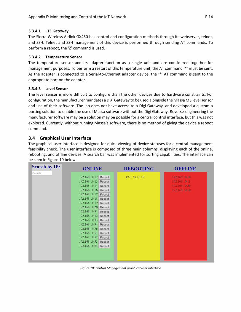
3.4 Graphical User Interface The graphical user interface is designed for quick viewing of device statuses for a central management feasibility check. The user interface is composed of three main columns, displaying each of the online, rebooting, and offline devices. A search bar was implemented for sorting capabilities. The interface can be seen in Figure 10 below.
Figure 10: Central Management graphical user interface

Appendix F: Monitoring and Control of the IoT Network F-15
To sort the devices into proper columns, the system runs the online status check. As results return from the status check, the device name is transferred into the appropriate online, rebooting, or offline column.
4 Cloud Implementation Specifics This section will focus on describing specifically how various tools were used and implemented for the cloud-based implementation. Specific device command implementations, the graphical user interface, and other aspects remain the same as in the local implementation and can be referenced in section 3. Three major changes occur in the transition from the local setup to the cloud-based implementation. The database and user connection functional parts are moved from within the management server to the cloud. This also results in the user interface moving from the management server to any computer with internet access. These changes provide management capability from outside the IoT network and limitless scalability without physical hardware changes. A figure explanation of the cloud setup can be seen in Figure 11, with the five functional parts once again highlighted in pink for comparison to the local setup shown in Figure 1 in Section 2.1. The remaining elements in the management control simply compose the physical network setup. A change in these would be a network structure change.
Figure 11: Data flow for cloud-based management platform
4.1 Storage Server The storage server structure for the cloud implementation is the same as in section 3.1. The MongoDB server was deployed using Azure CosmosDB servers rather than on a local management server for the

Appendix F: Monitoring and Control of the IoT Network F-16
cloud implementation. This simply required creating a CosmosDB database with MongoDB as the database structure and then creating the same ‘devices’ collection and populating it with all device info.
4.2 User Connection Devices are sent commands via Azure IoT Hub. In the prototype development, devices are referenced and named by their IP address inside the hub. This enables a single payload string to be repurposed. The central management platform calls a function for the device’s IP address and sends the same IP address in the payload. This allows the server to know where the command’s IP destination is without cross-referencing a device name to an address. The MQTT protocol is used for messaging to and from the IoT Hub, with symmetric keys being used as the authentication scheme for the management platform prototype.
4.3 Device Management This section presents the backend of the cloud-based setup. As the majority of the device management implementation is the same as in the local version, and to avoid redundancy, please refer to subsections of section 3 for implementation details missing within this cloud-based section.
4.3.1 Management Server Due to the physical network structure design, devices such as radios and cameras are hidden inside a private network and most do not have direct access to the public cloud. This physical design leads to data and communication needing to be routed to a node that has access to the public internet in order to use cloud based tools like Azure. Managing devices through Azure IoT Hub is therefore accomplished through using a server to listen and maintain multiple device connections to the central IoT hub and send the command on to the appropriate device. Command responses are returned to the server and sent back to the central hub and eventually the command triggering device. This server runs a node.js program which maintains the before-mentioned connections and sends commands to the appropriate device. While the central management server functioned properly most of the time, there was a stability issue relating to the Azure IoT Hub Node.js SDK. The Azure IoT Hub Node.js SDK appears to have a bug when using the symmetric key authentication scheme. Occasionally, an error is triggered by the MQTT client software that can cause the entire system to crash. The error appears to be related to renewing the shared access signature between devices. The X.509 certificate authentication protocol does not have this error and to enable maximum security, should be used to authenticate anyway. Information and progress relating to this bug can be read at https://github.com/Azure/azure-iot-sdk-node/issues/19#issuecomment-320677269. Another issue encountered was that occasionally certain device connection string connections are lost and become considered ‘undefined’. This may also be related to symmetric key authentication problems, but has not been verified.
5 Guidelines Table 1: Guideline Protocols for Managing devices
Wi-Fi Radios Cameras Adapters Sierra Wireless
Recommended protocols
SSH ONVIF, HTTPS SSH SSH
Other protocols
SNMPv3 SNMPv3 SNMPv3

Appendix F: Monitoring and Control of the IoT Network F-17
Can be used but not recommended
Telnet Telnet Telnet
This section highlights guideline recommendations of device capabilities for easier management and control of devices. Relatively few protocols are listed due to a lack of other protocol support in our devices as well as few dedicated management protocols. The recommended protocols above maintain high levels of security in addition to a simplified management system. The other protocols listed may not have the same level of security at present. SNMP is designed for network management, but focuses mainly on traffic monitoring and as a result does not seem as effective in developing a central management platform. There may be movements to provide more standardization of device management and control, but the lab is not aware of any at present.
6 Conclusions Although many IoT platforms were developed, most of them can only support a limited number of device manufacturers and models. As a result, a flexible, adaptable and customizable centralized data management structure is one of the most important components in a Smart City setup to prevent service/device provider lock-in. Central monitoring and control was found to be feasible, albeit requiring some custom solutions. Due to an overall lack of standardization across device types, multi-vendor support is not always easy to implement. Customized software was required to enable the same functionality to be integrated into a central platform. SSH was found to be an effective protocol that enabled simple management functions to be performed while maintaining a high level of security. Central management of the system can be performed with use of cloud services or on the local network. Currently, due to the network structure in the current prototype smart city, the main integration difference between cloud and local is the connection to public internet. The two systems could likely become much different in implementation If devices were deployed with their own LTE cards. Further research into standardization is still needed. Standardization could provide much easier network and management scalability.

Appendix F: Monitoring and Control of the IoT Network F-18
7 References
[1] Ubiquiti Networks, "airControl Network Management Application Release Version: 2," 2016.
[Online]. Available: https://dl.ubnt.com/guides/aircontrol/airControl_UG.pdf. [Accessed 10 August
2017].
[2] Axis Communications, "Axis Camera Management," 2016. [Online]. Available:
https://www.axis.com/files/datasheet/ds_camera_management_58318_en_1611.pdf. [Accessed
11 August 2017].
[3] Hangzhou Hikvision Digital Technology Co. Ltd., "iVMS-4200 Client Software User Manual,"
Hikvision, 2017.
[4] Panasonic, "Operating Instructions PC Software Package Model No. WV-ASM200," Panasonic, 2017.
[5] Microsoft, "Azure solutions for Internet of Things (IoT Suite) | Microsoft Docs," 2017. [Online].
Available: https://opbuildstorageprod.blob.core.windows.net/output-pdf-files/en-us/Azure.azure-
documents/live/iot-hub.pdf. [Accessed 11 August 2017].
[6] Node.js, "About Node.js," 2017. [Online]. Available: https://nodejs.org/en/about/. [Accessed 14
August 2017].
[7] GitHub, "Electron Documentation," GitHub, 2017. [Online]. Available:
https://electron.atom.io/docs/. [Accessed 12 August 2017].
[8] Open Network Video Interface Forum Inc., "ONVIF Application Programmer's Guide," May 2011.
[Online]. Available: https://www.onvif.org/wp-content/uploads/2016/12/ONVIF_WG-APG-
Application_Programmers_Guide-1.pdf.