appl. note, tech. info, white paper, edu. note (pad-t) · gfm325_0e rohde & schwarz 5g nr base...
TRANSCRIPT

5G NR Base Station Receiver Tests (Radiated conformance testing)
according to 38.141 Release 16
Application Note
Products:
ı R&S®ATS1800C
ı R&S®SMW200A
ı R&S®FSW
3GPP TS38.141-2 defines radiated conformance tests for 5G NR base stations. This application note
describes all required receiver (Rx) tests (TS38.141-2 Chapter 7) according to Release 16. Test 7.7 OTA
receiver spurious emissions requires an additional spectrum analyzer.
Note:
Visit our homepage for the most recent version of this application note
https://www.rohde-schwarz.com/appnote/GFM325
App
licat
ion
Not
e
Chr
istia
n W
icke
, Fab
ian
Bet
te
1.20
20 –
GF
M32
5_0e

Table of Contents
GFM325_0e Rohde & Schwarz 5G NR Base Station Receiver Tests
2
Table of Contents
1 Introduction ......................................................................................... 4
2 General ................................................................................................ 6
2.1 Base station classes and configurations .................................................................. 6
2.1.1 Classes .......................................................................................................................... 6
2.1.2 Configuration .................................................................................................................. 7
2.2 Rx Test Setup ............................................................................................................... 8
2.3 Chamber system, instruments and software options .............................................. 8
2.4 Reference coordinate system ..................................................................................... 9
3 Basics about OTA testing and ATS1800C ...................................... 10
3.1 5G OTA Calibration ....................................................................................................10
3.2 Effective isotropic radiated power (EIRP) ...............................................................10
3.3 Total radiated power (TRP) .......................................................................................11
3.4 R&S®ATS1800C (Compact Antenna Test Range OTA test system) .....................11
3.4.1 CATR principles ...........................................................................................................13
4 Receiver Tests (Chapter 7) ............................................................... 14
4.1 OTA sensitivity (7.2) ..................................................................................................16
4.2 OTA reference sensitivity level (7.3) ........................................................................17
4.3 OTA dynamic range (7.4) ..........................................................................................20
4.4 OTA in-band selectivity and blocking (7.5) .............................................................21
4.4.1 OTA adjacent channel selectivity (7.5.1) .....................................................................21
4.4.2 OTA in-band blocking (7.5.2) .......................................................................................24
4.5 OTA out-of-band blocking (7.6) ................................................................................31
4.5.1 General OTA out-of-band blocking ..............................................................................31
4.5.2 Co-location blocking.....................................................................................................33
4.6 OTA receiver spurious emissions (7.7) ...................................................................35
4.7 OTA receiver intermodulation (7.8) ..........................................................................38
4.7.1 General intermodulation ..............................................................................................39
4.7.2 Narrowband intermodulation ........................................................................................41
4.8 OTA in-channel selectivity (7.9) ...............................................................................43
5 Literature ........................................................................................... 48
6 Ordering Information ........................................................................ 49
A Test requirements ......................................................................................................50
Table of Contents
GFM325_0e Rohde & Schwarz 5G NR Base Station Receiver Tests
3
A.1 OTA dynamic range (7.4) ............................................................................................50

Introduction
GFM325_0e Rohde & Schwarz 5G NR Base Station Receiver Tests
4
1 Introduction
5G New Radio (NR) aims on three main services:
ı High data rate services (Enhanced Mobile Broad Band = eMBB)
ı Massive internet of things (Massive Machine Type Communication = mMTC)
ı Ultra reliable low latency communications (URLLC)
An overview of the technology behind 5G NR is provided in the Rohde & Schwarz book
[1].
The 5G NR conformance tests for base stations are defined in 3GPP TS 38.141
Release 16 and include transmitter (Tx), receiver (Rx) and performance (Px) tests.
3GPP defines two parts:
ı TS 38.141-1: Part 1: Conducted conformance testing [2]
ı TS 38.141-2: Part 2: Radiated conformance testing [3]
This application note has been written on the basis of Release 16, V16.1.0.
T&M instruments from Rohde & Schwarz can be used to perform all tests easily and
conveniently.
The application note describes the OTA Receiver (Rx) tests in line with TS38.141-2
chapter 7.
OTA transmitter (Tx) tests (TS38.141-2 Chapter 6) are described in Application Note
GFM324.
Table 1-1 gives an overview of the receiver tests defined in line with chapter 7 of
TS38.141-2. All can be carried out using instruments from Rohde & Schwarz. These
tests are individually described in this application note.
Table 1-1: OTA Receiver tests
Chapter Test Single Carrier (SC)
Multi Carrier (MC)
7.2 OTA sensitivity
7.3 OTA reference sensitivity level
7.4 OTA dynamic range
7.5.1 OTA adjacent channel selectivity
7.5.2 OTA in-band blocking
7.6 OTA out-of-band blocking
7.7 OTA receiver spurious emissions
7.8 OTA receiver intermodulation
7.9 OTA in-channel selectivity
: included in this application note
: not included in this application note

Introduction
GFM325_0e Rohde & Schwarz 5G NR Base Station Receiver Tests
5
The following abbreviations for Rohde & Schwarz test- and measurement equipment
are used in this application note:
ı The R&S®ATS1800C CATR conformance chamber system is referred to
ATS1800C
ı The R&S®SMW200A vector signal generator is referred to as the SMW
ı The R&S®FSW spectrum analyzer is referred to as the FSW

General
GFM325_0e Rohde & Schwarz 5G NR Base Station Receiver Tests
6
2 General
2.1 Base station classes and configurations
2.1.1 Classes
The specification distinguishes three different base station classes (38.141-2, chapter
4.3).
Table 2-1 Base station classes - BS to UE minimum coupling loss
Base station type Name Cell size Minimum coupling loss
BS type 1-H Wide area Macro cell 70 dB
Medium range Micro cell 53 dB
Local area Pico cell 45 dB
Table 2-2 Base station classes - BS to UE minimum distance along the ground
Base station type Name Cell size Minimum distance along the ground
BS type 1-O and BS type 2-O
Wide area Macro cell 35 m
Medium range Micro cell 5 m
Local area Pico cell 2 m

General
GFM325_0e Rohde & Schwarz 5G NR Base Station Receiver Tests
7
2.1.2 Configuration
This application note covers radiated measurements. In [3] three different base station
types are defined.
BS type 1-H (FR1 hybrid)
This type has two reference points. First the transceiver array boundary (TAB) which is
equipped with connectors for conducted measurements. Second the radiated interface
boundary (RIB). All measurements in this application note apply for the RIB (OTA).
Fig. 2-1: Radiated and conducted reference points for BS type 1-H [3]
BS type 1-O and 2-O
Fig. 2-2: General architecture of BS type 1-O and BS type 2-O [3]
#1
#2
#K
Transceiver array boundary Radiated interface boundary (RIB)
Transceiver array boundary connector (TAB)
Composite antenna
Radio Distribution
NetworkRDN
Antenna Array(AA)
Transceiver unit array(TRXUA)1 to M
Radiated interface boundary (RIB)
Composite antenna
Radio Distribution
NetworkRDN
Antenna Array(AA)
Transceiver unit array(TRXUA)
1 to P

General
GFM325_0e Rohde & Schwarz 5G NR Base Station Receiver Tests
8
2.2 Rx Test Setup
Fig. 2-3 shows the general test setup for receiver tests. A vector signal generator is
used to perform the tests. Some test require special setups which are described in the
respective sections.
Fig. 2-3: Complete Rx test setup overview
2.3 Chamber system, instruments and software options
For OTA tests in FR2 the following chamber system is used:
ı R&S®ATS1800C CATR based 5G NR mmWave test chamber
For base stations also operating in FR1 (BS type 1-O or BS type 1-H) the ATS1800C
CATR is not suitable. Please contact us for finding a customized solution.
The following vector signal generator can be used for the tests described here:
ı R&S®SMW200A with R&S®SZU100A IQ Upconverter (58.32 GHz to 64.80 GHz)
The 5G NR software option is needed for the Rx tests:
ı SMW-K144 5G New Radio
A few tests require an additional CW signal generator:
ı R&S® SMF100A with R&S® SMZ75
The OTA receiver spurious emissions test (7.7) requires a spectrum analyzer. The
following is recommended:
ı R&S®FSW

General
GFM325_0e Rohde & Schwarz 5G NR Base Station Receiver Tests
9
2.4 Reference coordinate system
For radiated tests a reference coordinate system is required. The reference coordinate
system should be associated to an identifiable physical feature on the base station
enclosure.
The reference coordinate system is created of a cartesian coordinate system with
rectangular axis 𝑥, 𝑦, 𝑧 and spherical angles 𝜃, 𝜑 as showed in Fig. 2-4. [3]
Fig. 2-4: Reference coordinate system [3]

Basics about OTA testing and ATS1800C
GFM325_0e Rohde & Schwarz 5G NR Base Station Receiver Tests
10
3 Basics about OTA testing and ATS1800C
3.1 5G OTA Calibration
In order to carry out accurate measurements, the OTA system must be calibrated prior
to performing the tests. For this purpose the user defined frequency response
correction options SMW-K544 and the FSW-K544 are used. More information can be
found in [4] and [5].
The system loss (cable losses, antennas losses, OTA losses, etc.) is measured with a
CW signal, which is swept over the frequency. For every frequency step the received
power is measured and an attenuation table is created:
For more information about OTA calibration see the following list:
ı Rohde & Schwarz, Demystifying over-the-air (OTA) testing - White paper, 2019
https://www.rohde-schwarz.com/de/loesungen/test-and-measurement/wireless-
communication/wireless-5g-and-cellular/5g-test-and-measurement/ota-white-
paper_251028.html
ı Demystifying 5G – System calibration basics for over-the-air (OTA) testing
https://www.youtube.com/watch?v=9NzRTnRTEYY
ı Demystifying 5G – Calibrating OTA test systems using gain transfer method
https://www.youtube.com/watch?v=RyFBfctYuk8
3.2 Effective isotropic radiated power (EIRP)
The EIRP denotes the absolute output power in a given direction. If no direction is
defined, the direction of maximum radiation intensity is implied. The EIRP is the power
an ideal isotropic radiator requires as input power to achieve the same power density
in the given direction. EIRP is the power accepted by the antenna multiplied by the
antenna gain, or radiated power multiplied by the directivity [6]:
𝐸𝐼𝑅𝑃 = 𝑃𝑖𝑛 ∙ 𝐺 𝐸𝐼𝑅𝑃𝑑𝐵𝑚 = 𝑃𝑖𝑛,𝑑𝐵𝑚 + 𝐺𝑑𝐵𝑖
Sweep CW signalMeasure received
powerCreate attenuation
table
Apply attenuation tabel and
reference antenna gain table to K544

Basics about OTA testing and ATS1800C
GFM325_0e Rohde & Schwarz 5G NR Base Station Receiver Tests
11
3.3 Total radiated power (TRP)
The power radiated by the antenna (𝑃𝑟𝑎𝑑) is also called the total radiated power (𝑃𝑇𝑅𝑃).
It is defined as the radiant intensity 𝐼(𝜃, 𝜑) integrated over the whole sphere around the
antenna:
Fig. 3-1: TRP integral
𝑃𝑇𝑅𝑃 = ∫ ∫ 𝐼(𝜃, 𝜑) ∙ sin 𝜃 𝑑𝜃𝑑𝜑
𝜋
𝜃=0
2𝜋
𝜑=0
The radiant intensity 𝐼 is expressed in Watt per steradian (𝑊
𝑠𝑟), thus the radiant flux
transmitted per solid angle. [6]
3.4 R&S®ATS1800C (Compact Antenna Test Range OTA test
system)
The R&S ATS1800C is a CATR OTA test system which is built for the OTA
characterization of DUTs for 5G mobile communication. The quiet zone is about 30 cm
and the maximum DUT weight is 8 kg. [7]
If your DUT exceeds these restrictions, please contact us for finding a customized
solution.
The ATS1800C provides RF feedthroughs for connecting the measurement devices.
They are located at the rear of the chamber (see Fig. 3-2).
Fig. 3-2: Feedthroughs R&S®ATS1800C [8]

Basics about OTA testing and ATS1800C
GFM325_0e Rohde & Schwarz 5G NR Base Station Receiver Tests
12
The following coordinate systems are used:
Fig. 3-3: Coordinate system R&S®ATS1800C
Fig. 3-4: Coordinate system R&S®ATS1800C [8]

Basics about OTA testing and ATS1800C
GFM325_0e Rohde & Schwarz 5G NR Base Station Receiver Tests
13
3.4.1 CATR principles
Inside the fully shielded chamber is the compact antenna test range (CATR) consisting
of a feed antenna, a bidirectional parabolic reflector and a 3D positioner. The reflector
has an extremely high precision surface roughness, which minimizes the errors
introduced by the reflection. This allows the reflector to be used in a very wide
frequency range for accurate measurement results. [7]
Fig. 3-5: R&S®ATS1800C CATR [7]
Fig. 3-6: Wave propagation in the CATR setup [8]

Receiver Tests (Chapter 7)
GFM325_0e Rohde & Schwarz 5G NR Base Station Receiver Tests
14
4 Receiver Tests (Chapter 7)
Specification TS38.141-2 defines the tests required in the various frequency ranges
(bottom, middle, top, B M T) of the operating band. In instruments from
Rohde & Schwarz, the frequency range can be set to any frequency within the
supported range independently of the operating bands.
Please note that this version of the application note supports single carrier (SC) tests
only.
In order to allow comparisons between tests, fixed reference channels (FRCs)
standardize the resource block (RB) allocations. The FRCs are stored as predefined
settings in instruments from Rohde & Schwarz.
Table 4-1 provides an overview of the basic parameters for the individual tests. The
channels to be tested (B M T) are included.
Table 4-1: Rx basic parameters overview
Chapter Test TE RFCh
7.2 OTA sensitivity N M
7.3 OTA reference sensitivity level N B, M, T
7.4 OTA dynamic range N M
7.5.1 OTA adjacent channel selectivity N M
7.5.2 OTA in-band blocking N M
7.6 OTA out-of-band blocking N M
7.7 OTA receiver spurious emissions N B/T
7.8 OTA receiver intermodulation N M
7.9 OTA in-channel selectivity N M
TE: Test environment
N: normal
RFCh: RF channels to be tested for single carrier
B: bottom
M: middle
T: top

Receiver Tests (Chapter 7)
GFM325_0e Rohde & Schwarz 5G NR Base Station Receiver Tests
15
In TS38.141-2, version 16.1.0 most of the requirements for base station type 1-H are
not available at this moment. Table 4-2 gives you an overview.
Table 4-2: Available requirements (TS38.141-2, version 16.1.0)
Requirement Requirement set
BS type 1-H BS type 1-O BS type 2-O
OTA sensitivity 7.2 7.2 N/A
OTA reference sensitivity level
N/A
7.3 7.3
OTA dynamic range 7.4 N/A
OTA in-band selectivity and blocking 7.5 7.5
OTA out-of-band blocking 7.6 7.6
OTA receiver spurious emission 7.7 7.7
OTA receiver intermodulation 7.8 7.8
OTA in-channel selectivity 7.9 7.9
Unless otherwise stated, the following arrangements apply for radiated receiver
characteristics requirements [3]:
ı Requirements apply during the base station receive period
ı Requirements shall be met for any transmitter setting
ı For FDD operation the requirements shall be met with the transmitter unit(s) ON
ı Throughput requirements defined for the radiated receiver characteristics do not
assume HARQ retransmissions
ı For ACS, blocking and intermodulation characteristics, the negative offsets of the
interfering signal apply relative to the lower Base Station RF Bandwidth edge or
sub-block edge inside a sub-block gap, and the positive offsets of the interfering
signal apply relative to the upper Base Station RF Bandwidth edge or sub-block
edge inside a sub-block gap.
For FR1 requirements which are to be met over the OTA REFSENS RoAoA absolute
requirement values are offset by the following term:
Δ𝑂𝑇𝐴𝑅𝐸𝐹𝑆𝐸𝑁𝑆 = 44.1 − 10 ∙ log10(𝐵𝑒𝑊𝜃,𝑅𝐸𝐹𝑆𝐸𝑁𝑆 ∙ 𝐵𝑒𝑊𝜑,𝑅𝐸𝐹𝑆𝐸𝑁𝑆) (for reference direction)
and
𝛥𝑂𝑇𝐴𝑅𝐸𝐹𝑆𝐸𝑁𝑆 = 41.1 − 10 ∙ log10(𝐵𝑒𝑊𝜃,𝑅𝐸𝐹𝑆𝐸𝑁𝑆 ∙ 𝐵𝑒𝑊𝜑,𝑅𝐸𝐹𝑆𝐸𝑁𝑆) (for all other directions)
For requirements which are to be met over the minSENS RoAoA absolute requirement
values are offset by the following term:
Δ𝑚𝑖𝑛𝑆𝐸𝑁𝑆 = 𝑃𝑅𝐸𝐹𝑆𝐸𝑁𝑆 − 𝐸𝐼𝑆𝑚𝑖𝑛𝑆𝐸𝑁𝑆
For FR2 requirements which are to be met over the OTA REFSENS RoAoA absolute
requirement values are offset by the following term:
Δ𝐹𝑅2_𝑅𝐸𝐹𝑆𝐸𝑁𝑆 = −3 𝑑𝐵 (for the reference direction)
𝛥𝐹𝑅2_𝑅𝐸𝐹𝑆𝐸𝑁𝑆 = 0 𝑑𝐵 (for all other directions)

Receiver Tests (Chapter 7)
GFM325_0e Rohde & Schwarz 5G NR Base Station Receiver Tests
16
4.1 OTA sensitivity (7.2)
The OTA sensitivity requirement is based upon the declaration of one or more OTA
sensitivity direction declarations (OSDD). The test purpose is to verify that the BS can
meet the throughput requirement for a specified measurement channel at the EIS level
and the range of angles of arrival declared in the OSDD.
This test is not applicable for BS type 2-O. For BS type 2-O the OTA sensitivity is the
same as the OTA reference sensitivity in subclause 4.2. [3]
For each measured carrier, the throughput measured shall be ≥ 95 % of the maximum
throughput of the reference measurement channel with parameters specified in Table
4-3 [3].
Table 4-3: Test requirements for BS type 1-H and BS type 1-O; EIS levels [3]
BS channel
bandwidth
(MHz)
SCS
(kHz)
Reference
measurement
channel
EIS level (dBm)
f ≤ 3.0 GHz 3.0 GHz < f ≤ 4.2
GHz
4.2 GHz < f ≤ 6.0
GHz
5, 10, 15 15 G-FR1-A1-1 Declared
minimum EIS +
1.3
Declared
minimum EIS +
1.4
Declared
minimum EIS +
1.6 10, 15 30 G-FR1-A1-2
10, 15 60 G-FR1-A1-3
20, 25, 30, 40,
50
15 G-FR1-A1-4
20, 25, 30, 40,
50, 60, 70, 80,
90, 100
30 G-FR1-A1-5
20, 25, 30, 40,
50, 60, 70, 80,
90, 100
60 G-FR1-A1-6
At this moment test requirement for BS type 2-O is not available.
Test setup
Fig. 4-1: Test setup OTA sensitivity
Receiver Tests (Chapter 7)
GFM325_0e Rohde & Schwarz 5G NR Base Station Receiver Tests
17
Procedure
1. Place the base station at the positioner and align the coordinate system
2. Align the base station with the test antenna in the declared direction to be tested
(all the power from the test antenna is captured by the BS)
3. Configure beam peak direction according to the declared reference beam
direction pair
4. Set the BS to transmit beams of the same operational band as the OSDD being
tested
5. Set the SMW to transmit a 5G NR test signal according to Table 4-3
6. Measure the throughput for each supported polarization
Repeat steps 3) to 9) for all OSDD(s) declared for the BS and supported polarizations
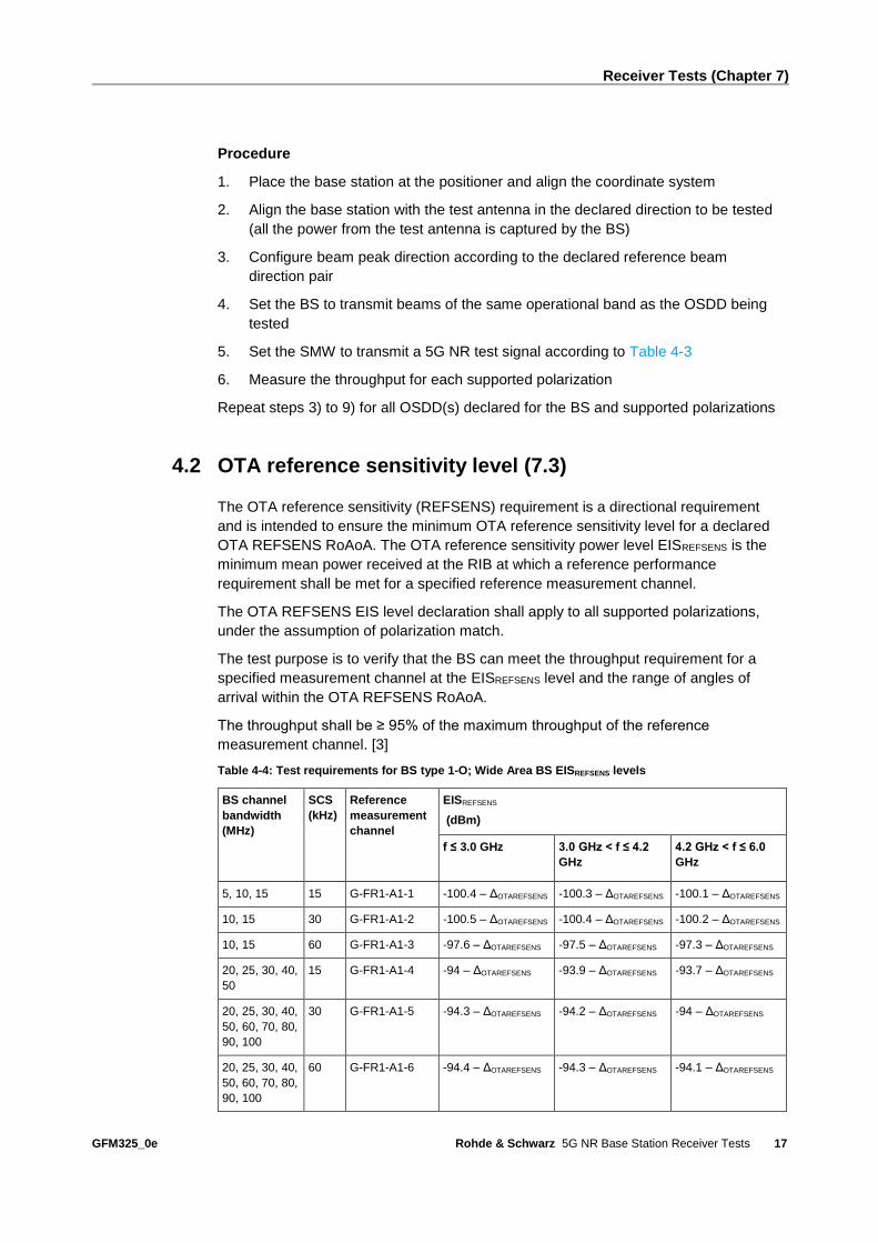
4.2 OTA reference sensitivity level (7.3)
The OTA reference sensitivity (REFSENS) requirement is a directional requirement
and is intended to ensure the minimum OTA reference sensitivity level for a declared
OTA REFSENS RoAoA. The OTA reference sensitivity power level EISREFSENS is the
minimum mean power received at the RIB at which a reference performance
requirement shall be met for a specified reference measurement channel.
The OTA REFSENS EIS level declaration shall apply to all supported polarizations,
under the assumption of polarization match.
The test purpose is to verify that the BS can meet the throughput requirement for a
specified measurement channel at the EISREFSENS level and the range of angles of
arrival within the OTA REFSENS RoAoA.
The throughput shall be ≥ 95% of the maximum throughput of the reference
measurement channel. [3]
Table 4-4: Test requirements for BS type 1-O; Wide Area BS EISREFSENS levels
BS channel
bandwidth
(MHz)
SCS
(kHz)
Reference
measurement
channel
EISREFSENS
(dBm)
f ≤ 3.0 GHz 3.0 GHz < f ≤ 4.2
GHz
4.2 GHz < f ≤ 6.0
GHz
5, 10, 15 15 G-FR1-A1-1 -100.4 – ΔOTAREFSENS -100.3 – ΔOTAREFSENS -100.1 – ΔOTAREFSENS
10, 15 30 G-FR1-A1-2 -100.5 – ΔOTAREFSENS -100.4 – ΔOTAREFSENS -100.2 – ΔOTAREFSENS
10, 15 60 G-FR1-A1-3 -97.6 – ΔOTAREFSENS -97.5 – ΔOTAREFSENS -97.3 – ΔOTAREFSENS
20, 25, 30, 40,
50
15 G-FR1-A1-4 -94 – ΔOTAREFSENS -93.9 – ΔOTAREFSENS -93.7 – ΔOTAREFSENS
20, 25, 30, 40,
50, 60, 70, 80,
90, 100
30 G-FR1-A1-5 -94.3 – ΔOTAREFSENS -94.2 – ΔOTAREFSENS -94 – ΔOTAREFSENS
20, 25, 30, 40,
50, 60, 70, 80,
90, 100
60 G-FR1-A1-6 -94.4 – ΔOTAREFSENS -94.3 – ΔOTAREFSENS -94.1 – ΔOTAREFSENS

Receiver Tests (Chapter 7)
GFM325_0e Rohde & Schwarz 5G NR Base Station Receiver Tests
18
Table 4-5: Test requirements for BS type 1-O; Medium range BS EISREFSENS levels
BS channel
bandwidth
(MHz)
SCS
(kHz)
Reference
measurement
channel
EISREFSENS
(dBm)
f ≤ 3.0 GHz 3.0 GHz < f ≤ 4.2
GHz
4.2 GHz < f ≤ 6.0
GHz
5, 10, 15 15 G-FR1-A1-1 -95.4 – ΔOTAREFSENS -95.3 – ΔOTAREFSENS -95.1 – ΔOTAREFSENS
10, 15 30 G-FR1-A1-2 -95.5 – ΔOTAREFSENS -95.4 – ΔOTAREFSENS -95.2 – ΔOTAREFSENS
10, 15 60 G-FR1-A1-3 -92.6 – ΔOTAREFSENS -92.5 – ΔOTAREFSENS -92.3 – ΔOTAREFSENS
20, 25, 30, 40,
50
15 G-FR1-A1-4 -89 – ΔOTAREFSENS -88.9 – ΔOTAREFSENS -88.7 – ΔOTAREFSENS
20, 25, 30, 40,
50, 60, 70, 80,
90, 100
30 G-FR1-A1-5 -89.3 – ΔOTAREFSENS -89.2 – ΔOTAREFSENS -89 – ΔOTAREFSENS
20, 25, 30, 40,
50, 60, 70, 80,
90, 100
60 G-FR1-A1-6 -89.4 – ΔOTAREFSENS -89.3 – ΔOTAREFSENS -89.1 – ΔOTAREFSENS
Table 4-6: Test requirements for BS type 1-O; Local area BS EISREFSENS levels
BS channel
bandwidth
(MHz)
SCS
(kHz)
Reference
measurement
channel
EISREFSENS
(dBm)
f ≤ 3.0 GHz 3.0 GHz < f ≤ 4.2
GHz
4.2 GHz < f ≤ 6.0
GHz
5, 10, 15 15 G-FR1-A1-1 -92.4 – ΔOTAREFSENS -92.3 – ΔOTAREFSENS -92.1 – ΔOTAREFSENS
10, 15 30 G-FR1-A1-2 -92.5 – ΔOTAREFSENS -92.4 – ΔOTAREFSENS -92.2 – ΔOTAREFSENS
10, 15 60 G-FR1-A1-3 -89.6 – ΔOTAREFSENS -89.5 – ΔOTAREFSENS -89.3 – ΔOTAREFSENS
20, 25, 30, 40,
50
15 G-FR1-A1-4 -86 – ΔOTAREFSENS -85.9 – ΔOTAREFSENS -85.7 – ΔOTAREFSENS
20, 25, 30, 40,
50, 60, 70, 80,
90, 100
30 G-FR1-A1-5 -86.3 – ΔOTAREFSENS -86.2 – ΔOTAREFSENS -86 – ΔOTAREFSENS
20, 25, 30, 40,
50, 60, 70, 80,
90, 100
60 G-FR1-A1-6 -86.4 – ΔOTAREFSENS -86.3 – ΔOTAREFSENS -86.1 – ΔOTAREFSENS

Receiver Tests (Chapter 7)
GFM325_0e Rohde & Schwarz 5G NR Base Station Receiver Tests
19
Table 4-7: Test requirements for BS type 2-O; BS EISREFSENS levels
BS channel
bandwidth
(MHz)
SCS
(kHz)
Reference
measurement
channel
EISREFSENS level
(dBm)
50, 100, 200 60 G-FR2-A1-1 EISREFSENS_50M + 2.4 + ΔFR2_REFSENS
50 120 G-FR2-A1-2 EISREFSENS_50M + 2.4 + ΔFR2_REFSENS
100, 200, 400 120 G-FR2-A1-3 EISREFSENS_50M + 3 + 2.4 + ΔFR2_REFSENS
Table 4-8: EISREFSENS_50M value range
BS class EISREFSENS_50M value range
Wide are BS -119 dBm ≤ EISREFSENS_50M ≤ -96 dBm
Medium range BS -114 dBm ≤ EISREFSENS_50M ≤ -91 dBm
Local area BS -109 dBm ≤ EISREFSENS_50M ≤ -86 dBm
Test setup
Fig. 4-2: Measurement setup for OTA reference sensitivity level
Procedure
1. Place the base station at the positioner and align the coordinate system
2. Align the base station with the test antenna in the declared direction to be tested
(all the power from the test antenna is captured by the BS)
3. Configure beam peak direction according to the declared reference beam
direction pair
4. Set the BS to transmit beams of the same operational band as the OSDD being
tested
5. Set the SMW to transmit a 5G NR test signal according to Table 4-4 to Table 4-7
6. Measure the throughput for each supported polarization
Repeat steps 3) to 9) for all OSDD(s) declared for the BS and supported polarizations

Receiver Tests (Chapter 7)
GFM325_0e Rohde & Schwarz 5G NR Base Station Receiver Tests
20
4.3 OTA dynamic range (7.4)
The OTA dynamic range is a measure of the capability of the receiver unit to receive a
wanted signal in the presence of an interfering signal inside the received BS channel
bandwidth. The requirement shall apply at the RIB when the AoA of the incident wave
of a received signal and the interfering signal are from the same direction and are
within the OTA REFSENS RoAoA. The test purpose is to verify that at the BS receiver
dynamic range, the relative throughput shall fulfil the specified limit. [3]
The interfering signal is an AWGN signal.
The test requirements will be found in A.1 (at this moment test requirement for BS type
2-O is missing in the specification). For each measured carrier, the measured
throughput shall be ≥ 95 % of the maximum throughput of the reference measurement
channel. [3]
Fig. 4-3: Dynamic range
Test setup
Fig. 4-4: Measurement setup for OTA dynamic range

Receiver Tests (Chapter 7)
GFM325_0e Rohde & Schwarz 5G NR Base Station Receiver Tests
21
Procedure
1. Place the base station at the positioner and align the coordinate system
2. Align the base station with the test antenna in the declared direction to be tested
(all the power from the test antenna is captured by the BS)
3. Configure beam peak direction according to the declared reference beam
direction pair
4. Set the BS to transmit beams of the same operational band as the OTA
REFSENS RoAoA being tested
5. Set the SMW to transmit the test signal (with AWGN interferer in the same
channel)
a) Set the SMW to transmit the 5G NR signal according to Table 6-1 to Table
6-3
b) Set the AWGN frequency at the same frequency as the NR signal with power
settings according to Table 6-1 to Table 6-3
6. Measure the throughput for each supported polarization
4.4 OTA in-band selectivity and blocking (7.5)
This part demonstrates tests with in-band interferers.
4.4.1 OTA adjacent channel selectivity (7.5.1)
OTA adjacent channel selectivity (ACS) is a measure of the receiver’s ability to receive
an OTA wanted signal at its assigned channel frequency in the presence of an OTA
adjacent channel signal with a specified center frequency offset of the interfering signal
to the band edge of a victim system. The wanted and interfering signals apply to all
supported polarizations, under the assumption of polarization match. The test purpose
is to verify the ability of the BS receiver filter to suppress interfering signals in the
channels adjacent to the wanted channel.
The throughput shall be ≥ 95% of the maximum throughput of the reference
measurement channel. [3]

Receiver Tests (Chapter 7)
GFM325_0e Rohde & Schwarz 5G NR Base Station Receiver Tests
22
Fig. 4-5: ACS
Table 4-9: OTA ACS requirement for BS type 1-O
BS channel
bandwidth of the
lowest/highest
carrier received
(MHz)
Wanted signal mean power (dBm) Interfering signal mean power
(dBm)
f ≤ 3.0
GHz
3.0 GHz < f ≤
4.2 GHz
4.2 GHz < f ≤
6.0 GHz
5, 10, 15, 20, 25,
30, 40, 50, 60, 70,
80, 90, 100
EISminSENS + 6 dB Wide Area: -52 – ΔminSENS
Medium Range: -47– ΔminSENS
Local Area: -44– ΔminSENS
Note: EISminSENS is specified in TS38.104 [9].
Table 4-10: OTA ACS interferer frequency offset for BS type 1-O
BS channel
bandwidth of the
lowest/highest
carrier received
(MHz)
Interfering signal center frequency
offset from the lower/upper Base
Station RF Bandwidth edge or sub-
block edge inside a sub-block gap
(MHz)
Type of interfering signal
5 ±2.5025 5MHz DFT-s-OFDM NR signal, 15kHz
SCS, 25 RBs 10 ±2.5075
15 ±2.5125
20 ±2.5025
25 ±9.4675 20MHz DFT-s-OFDM NR signal, 15kHz
SCS, 100 RBs 30 ±9.4725
40 ±9.4675
50 ±9.4625
60 ±9.4725
70 ±9.4675
80 ±9.4625
90 ±9.4725
100 ±9.4675

Receiver Tests (Chapter 7)
GFM325_0e Rohde & Schwarz 5G NR Base Station Receiver Tests
23
Table 4-11: OTA ACS requirement for BS 2-O
BS channel bandwidth of the
lowest/highest carrier received (MHz)
Wanted signal mean power
(dBm)
Interfering signal mean
power (dBm)
24.24 GHz < f ≤
33.4 GHz
37 GHz < f ≤
52.6 GHz
50, 100, 200, 400 EISREFSENS + 6 dB EISREFSENS + 6
dB
EISREFSENS_50M + 27.7 +
ΔFR2_REFSENS (Note 1)
EISREFSENS_50M + 26.7 +
ΔFR2_REFSENS (Note 2)
Note 1: Applicable to bands defined within the frequency spectrum range of
24.25 – 33.4 GHz
Note 2: Applicable to bands defined within the frequency spectrum range of
37 – 52.6 GHz
Table 4-12: OTA ACS interferer frequency offset for BS type 2-O
BS channel bandwidth of
the lowest/highest carrier
received (MHz)
Interfering signal centre frequency offset
from the lower/upper Base Station RF
Bandwidth edge or sub-block edge inside a
sub-block gap (MHz)
Type of interfering
signal
50 ±24.29 50MHz DFT-s-OFDM
NR signal, 60 kHz
SCS, 64 RBs 100 ±24.31
200 ±24.29
400 ±24.31
Test setup
Fig. 4-6: Measurement setup for OTA adjacent channel selectivity

Receiver Tests (Chapter 7)
GFM325_0e Rohde & Schwarz 5G NR Base Station Receiver Tests
24
Procedure
1. Place the base station at the positioner and align the coordinate system
2. Align the base station with the test antenna in the declared direction to be tested
(wanted signal and interferer signal is polarization matched with the test antenna)
3. Configure beam peak direction according to the declared reference beam
direction pair
4. Set the BS to transmit beams of the same operational band as the OSDD or
RoAoA being tested
5. SMW settings (use a hybrid combiner to sum all signals)
a) Path A (wanted signal): Transmit signal according to Table 4-9 and
Table 4-11
b) Path B (interfering signal): Transmit signal at the adjacent channel frequency
of the wanted signal (according to Table 4-10 and Table 4-12)
6. Measure throughput for each supported polarization
4.4.2 OTA in-band blocking (7.5.2)
The in-band blocking consist of two tests.
4.4.2.1 General blocking
In in-band blocking tests, the NR interfering signal center frequency is swept with a
step size of 1 MHz starting from the minimum offset to the channel edge of the wanted
signals.
Fig. 4-7: General in-band blocking

Receiver Tests (Chapter 7)
GFM325_0e Rohde & Schwarz 5G NR Base Station Receiver Tests
25
The throughput shall be ≥ 95% of the maximum throughput of the reference
measurement channel.
For BS type 1-O the OTA in-band blocking requirement shall apply in the in-band
blocking frequency range, which is defined within frequency range from FUL_low - ΔfOOB
to FUL_high + ΔfOOB, excluding the downlink frequency range of the FDD operating band,
where the ΔfOOB for BS type 1-O is defined in Table 4-13.
Table 4-13: ΔfOOB offset for NR operating bands in FR1
BS type Operating band characteristics ΔfOOB (MHz)
BS type 1-O FUL_high – FUL_low < 100 MHz 20
100 MHz ≤ FUL_high – FUL_low ≤ 900 MHz 60
For BS type 2-O the OTA blocking requirement shall apply in the in-band blocking
frequency range, which is defined within frequency range from FUL_low - ΔfOOB to
FUL_high + ΔfOOB, where the ΔfOOB for BS type 2-O is defined in Table 4-14.
Table 4-14: ΔfOOB offset for NR operating bands in FR2
BS type Operating band characteristics ΔfOOB (MHz)
BS type 2-O FUL_high – FUL_low ≤ 3250 MHz 1500
Table 4-15: General OTA blocking requirement for BS type 1-O
BS channel
bandwidth of the
lowest/highest
carrier received
(MHz)
Wanted signal mean
power (dBm)
Interfering signal
mean power
(dBm)
Interfering
signal center
frequency min.
offset from the
lower/upper BS
RF bandwidth
edge or sub-
block edge
inside a sub-
block gap (MHz)
Type of
interfering
signal f ≤ 3.0
GHz
3.0 GHz
< f ≤ 4.2
GHz
4.2 GHz
< f ≤
6.0 GHz
5, 10, 15, 20 EISREFSENS + 6 dB Wide Area: -43 -
ΔOTAREFSENS
Medium Range: -
38 - ΔOTAREFSENS
Local Area: -35 -
ΔOTAREFSENS
±7.5 5 MHz DFT-s-
OFDM NR
signal, 15 kHz
SCS, 25 RBs
EISminSENS + 6 dB Wide Area: -43 -
ΔminSENS
Medium Range: -
38 - ΔminSENS
Local Area: -35 -
ΔminSENS
25 ,30, 40, 50, 60,
70, 80, 90, 100
EISREFSENS + 6 dB Wide Area: -43 -
ΔOTAREFSENS
Medium Range: -
38 - ΔOTAREFSENS
Local Area: -35 -
ΔOTAREFSENS
±30 20 MHz DFT-
s-OFDM NR
signal, 15 kHz
SCS, 100 RBs

Receiver Tests (Chapter 7)
GFM325_0e Rohde & Schwarz 5G NR Base Station Receiver Tests
26
EISminSENS + 6 dB Wide Area: -43 -
ΔminSENS
Medium Range: -
38 - ΔminSENS
Local Area: -35 -
ΔminSENS
Table 4-16: General OTA blocking requirement for BS type 2-O
BS channel
bandwidth of
the
lowest/highe
st carrier
received
(MHz)
OTA wanted signal
mean power (dBm)
OTA interfering
signal mean power
(dBm)
OTA interfering
signal center
frequency offset
from the
lower/upper BS RF
Bandwidth edge or
sub-block edge
inside a sub-block
gap (MHz)
Type of OTA
interfering
signal
24.24 GHz
< f ≤ 33.4
GHz
37 GHz < f
≤ 52.6 GHz
50, 100, 200,
400
EISREFSENS +
6 dB
EISREFSENS +
6 dB
EISREFSENS_50M + 33
+ ΔFR2_REFSENS dB
±75 50 MHz DFT-s-
OFDM NR
signal, 60 kHz
SCS, 64 RBs
Test setup
Fig. 4-8: Measurement setup for general OTA blocking
Procedure
1. Place the base station at the positioner and align the coordinate system
2. Align the base station with the test antenna in the declared direction to be tested
(wanted signal and interferer signal is polarization matched with the test antenna)
3. Configure beam peak direction according to the declared reference beam
direction pair
4. Set the BS to transmit beam(s) of the same operational band as the OSDD or
OTA REFSENS RoAoA being tested

Receiver Tests (Chapter 7)
GFM325_0e Rohde & Schwarz 5G NR Base Station Receiver Tests
27
5. SMW settings (use a hybrid combiner to sum all signals)
a) Path A (wanted signal): Transmit signal according to Table 4-15 and Table
4-16
b) Path B (interfering signal): Set frequency offset from the wanted signal
according to Table 4-15 and Table 4-16
Interfering signal shall be swept with a step size of 1 MHz starting from the
minimum offset to the channel edges of the wanted signals.
6. Measure throughput for each supported polarization
Repeat steps 3) to 6) for all specified measurement directions
4.4.2.2 Narrowband blocking
The interferer is placed near the wanted signal. This test is available for BS type 1-O
only.
Fig. 4-9: Narrowband blocking

Receiver Tests (Chapter 7)
GFM325_0e Rohde & Schwarz 5G NR Base Station Receiver Tests
28
Table 4-17: OTA narrowband blocking requirement for BS type 1-O
BS channel
bandwidth of the
lowest/highest
carrier received
(MHz)
OTA Wanted signal mean power (dBm) OTA Interfering signal mean power
(dBm)
f ≤ 3.0 GHz 3.0 GHz < f
≤ 4.2 GHz
4.2 GHz < f ≤
6.0 GHz
5, 10, 15, 20 EISREFSENS + 6 dB Wide Area: -49 - ΔOTAREFSENS
Medium Range: -44 - ΔOTAREFSENS
Local Area: -41 - ΔOTAREFSENS
EISminSENS + 6 dB
Wide Area: -49 - ΔminSENS
Medium Range: -44 - ΔminSENS
Local Area: -41 - ΔminSENS
25, 30, 40, 50, 60, 70,
80, 90, 100
EISREFSENS + 6 dB Wide Area: -49 - ΔOTAREFSENS
Medium Range: -44 - ΔOTAREFSENS
Local Area: -41 - ΔOTAREFSENS
EISminSENS + 6 dB
Wide Area: -49 - ΔminSENS
Medium Range: -44 - ΔminSENS
Local Area: -41 - ΔminSENS
Table 4-18: OTA narrowband blocking interferer frequency offsets from BS type 1-O
BS channel bandwidth of the
lowest/highest carrier
received (MHz)
Interfering RB center frequency offset to the
lower/upper Base Station RF Bandwidth edge
or sub-block edge inside a sub-block gap
(kHz)
Type of interfering
signal
5 ±(350 + m*180),
m=0, 1, 2, 3, 4, 9, 14, 19, 24
5 MHz DFT-s-OFDM
NR signal, 15 kHz
SCS, 1 RB
10 ±(355 + m*180),
m=0, 1, 2, 3, 4, 9, 14, 19, 24
15 ±(360 + m*180),
m=0, 1, 2, 3, 4, 9, 14, 19, 24
20 ±(350 + m*180),
m=0, 1, 2, 3, 4, 9, 14, 19, 24
25 ±(565 + m*180),
m=0, 1, 2, 3, 4, 29, 54, 79, 99
20 MHz DFT-s-OFDM
NR signal, 15 kHz
SCS, 1 RB
30 ±(570 + m*180),
m=0, 1, 2, 3, 4, 29, 54, 79, 99
40 ±(565 + m*180),
m=0, 1, 2, 3, 4, 29, 54, 79, 99
50 ±(560 + m*180),
m=0, 1, 2, 3, 4, 29, 54, 79, 99
60 ±(570 + m*180),
m=0, 1, 2, 3, 4, 29, 54, 79, 99
70 ±(565 + m*180),
m=0, 1, 2, 3, 4, 29, 54, 79, 99
Receiver Tests (Chapter 7)
GFM325_0e Rohde & Schwarz 5G NR Base Station Receiver Tests
29
80 ±(560 + m*180),
m=0, 1, 2, 3, 4, 29, 54, 79, 99
90 ±(570 + m*180),
m=0, 1, 2, 3, 4, 29, 54, 79, 99
100 ±(565 + m*180),
m=0, 1, 2, 3, 4, 29, 54, 79, 99
Test setup
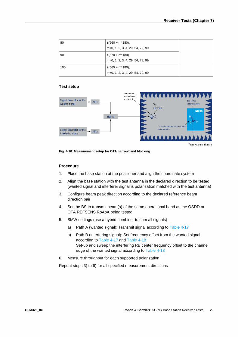
Fig. 4-10: Measurement setup for OTA narrowband blocking
Procedure
1. Place the base station at the positioner and align the coordinate system
2. Align the base station with the test antenna in the declared direction to be tested
(wanted signal and interferer signal is polarization matched with the test antenna)
3. Configure beam peak direction according to the declared reference beam
direction pair
4. Set the BS to transmit beam(s) of the same operational band as the OSDD or
OTA REFSENS RoAoA being tested
5. SMW settings (use a hybrid combiner to sum all signals)
a) Path A (wanted signal): Transmit signal according to Table 4-17
b) Path B (interfering signal): Set frequency offset from the wanted signal
according to Table 4-17 and Table 4-18
Set-up and sweep the interfering RB center frequency offset to the channel
edge of the wanted signal according to Table 4-18
6. Measure throughput for each supported polarization
Repeat steps 3) to 6) for all specified measurement directions

Receiver Tests (Chapter 7)
GFM325_0e Rohde & Schwarz 5G NR Base Station Receiver Tests
30
4.5 OTA out-of-band blocking (7.6)
The OTA out-of-band blocking characteristics are a measure of the receiver unit ability
to receive a wanted signal at the RIB at its assigned channel in the presence of an
unwanted interferer. For this test a CW interfering signal is required. [3]
4.5.1 General OTA out-of-band blocking
Table 4-19: OTA out-of-band blocking performance requirement for BS type 1-O
Wanted signal mean power
(dBm)
Interfering signal RMS field-strength
(V/m)
Type of interfering signal
EISminSENS + 6 dB 0.36 V/m CW carrier
The RMS field-strength level in V/m is related to the interferer EIRP level at a distance
described as 𝐸 = √30 𝐸𝐼𝑅𝑃
𝑟, where 𝐸𝐼𝑅𝑃 is in W and 𝑟 is in m
for example: 0.36 V/m is equivalent to 36 dBm at fixed distance of 30 m.
Note: More information about EIRP level can be found in 3.2.
Table 4-20: OTA out-of-band blocking performance requirement for BS 2-O
Frequency range of interfering signal
(MHz)
Wanted signal mean
power (dBm)
Interferer RMS
field-strength
(V/m)
Type of
interfering
signal
30 to 12750 EISREFSENS + 6 dB 0.36 CW
12750 to FUL_low – ΔfOOB 0.10
FUL_high + ΔfOOB to min (2nd harmonic of the
upper frequency edge of the operating
band, 60000)
0.10
The throughput shall be ≥ 95% of the maximum throughput of the reference
measurement channel.
Table 4-21: Interferer signal step size
Frequency range (MHz) Minimum supported BS channel
bandwidth (MHz)
Measurement step size (MHz)
30 to 6000 50, 100, 200, 400 1
6000 to 60000 50 15
100 30
200 60
400 60

Receiver Tests (Chapter 7)
GFM325_0e Rohde & Schwarz 5G NR Base Station Receiver Tests
31
Test setup
Fig. 4-11: Measurement setup for general OTA out-of-band blocking
Procedure
1. Place the base station at the positioner and align the coordinate system
2. Align the base station with the test antenna in the declared direction to be tested
(wanted signal and interferer signal is polarization matched with the test antenna)
3. Test antenna shall be dual polarized covering the same frequency ranges as the
BS and the blocking frequencies. If the test antenna does not cover both, separate
test antennas for the wanted and interfering signal are required.
4. The OTA blocking interferer is injected into the test antenna. The interferer shall
be polarization matched in-band and the polarization maintained for out-of-band
frequencies.
5. Generate the wanted signal according to the applicable test configuration
6. Configure beam peak direction according to the declared reference beam
direction pair. The transmitter may be turned OFF for the out-of-band blocker tests
when the frequency of the blocker is such that no IM2 or IM3 products fall inside
the bandwidth of the wanted signal.
7. Settings for the interfering signal according to Table 4-19
For generating the interfering signal you can use the second path of the SMW or
an external CW generator.
a) BS 1-O: The CW interfering signal shall be swept with a step size of 1 MHz
within the specified range
b) BS 2-O: the interfering signal shall be swept within the frequency range and
step size specified in Table 4-21
8. Measure the performance of the wanted signal at the receiver unit
9. Repeat the procedure for all supported polarizations

Receiver Tests (Chapter 7)
GFM325_0e Rohde & Schwarz 5G NR Base Station Receiver Tests
32
4.5.2 Co-location blocking
This test is available for BS type 1-O only.
Table 4-22: OTA blocking for co-location with BS in other frequency bands (for BS type 1-O)
Frequency range
of interfering
signal
Wanted signal
mean power
(dBm)
Interfering
signal mean
power for WA
BS (dBm)
Interfering
signal mean
power for MR
BS (dBm)
Interfering
signal mean
power for LA
BS (dBm)
Type of
interfering
signal
Frequency range of
co-located
downlink operating
band
EISminSENS +
6 dB
+46 +38 +24 CW carrier
The throughput shall be ≥ 95% of the maximum throughput of the reference
measurement channel.
Test setup
Fig. 4-12: Measurement setup for OTA co-location blocking
Table 4-23: CLTA alignment tolerances
Parameter
Edge-to-edge separation between the NR BS and the CLTA, d 0.1 m ± 0.01 m
Vertical alignment Centre ± 0.01 m
Front alignment Radome front ± 0.01 m

Receiver Tests (Chapter 7)
GFM325_0e Rohde & Schwarz 5G NR Base Station Receiver Tests
33
Fig. 4-13: Alignment of NR BS and CLTA [3]
Procedure
1. Place base station and CLTA (colocation test antenna) according to Table 4-23
and Fig. 4-13
2. Align the BS and test antenna according to the directions to be tested
3. The OTA co-location blocking interferer is injected via the CLTA
4. Generate the wanted signal
5. Configure beam peak direction according to the declared reference beam
direction pair. The transmitter may be turned OFF for the out-of-band blocker tests
when the frequency of the blocker is such that no IM2 or IM3 products fall inside
the bandwidth of the wanted signal.
6. Settings for the interfering signal according to Table 4-22
For generating the interfering signal you can use the second path of the SMW or
an external CW generator.
The CW interfering signal shall be swept with a step size of 1 MHz within the
specified range
7. Measure the performance of the wanted signal at the receiver unit
NR BS type 1-O CLTA
Horizontal View
Vertical View
d
Mechanical
bore-sight
direction
Mechanical
bore-sight
direction
Side View
Back side Front side

Receiver Tests (Chapter 7)
GFM325_0e Rohde & Schwarz 5G NR Base Station Receiver Tests
34
4.6 OTA receiver spurious emissions (7.7)
The OTA RX spurious emission is the power of the emissions radiated from the
antenna array from a receiver unit.
The OTA receiver spurious emission limits for FR1 shall apply from 30 MHz to
12.75 GHz, excluding the frequency range from ΔfOBUE (see ) below the lowest
frequency of each supported downlink operating band, up to ΔfOBUE above the highest
frequency of each supported downlink operating band.
The OTA receiver spurious emission limits for FR2 shall apply from 30 MHz to 2nd
harmonic of the upper frequency edge of the downlink operating band, excluding the
frequency range from ΔfOBUE (see ) below the lowest frequency of each supported
downlink operating band, up to ΔfOBUE above the highest frequency of each supported
downlink operating band.
For a BS operating in FDD, OTA RX spurious emissions requirement do not apply as
they are superseded by the OTA TX spurious emissions requirement. This is due to
the fact that TX and RX spurious emissions cannot be distinguished in OTA domain.
For a BS operating in TDD, the OTA RX spurious emissions requirement shall apply
during the transmitter OFF period only. [3]
Table 4-24: Maximum offset ΔfOBUE outside the downlink operating band
BS type Operating band characteristics ΔfOBUE (MHz)
BS type 1-O FDL_high – FDL_low < 100 MHz 10
100 MHz ≤ FDL_high – FDL_low ≤ 900 MHz 40
BS type 2-O FDL_high – FDL_low ≤ 3250 MHz 1500
The RF channels to be tested depend on the frequency ranges:
FR1
Testing from 30 MHz to FDL_low - ΔfOBUE RF channel: B
Testing from FDL_high + ΔfOBUE to 12.75 GHz (or to 5th harmonic)
RF channel: T
FR2
Testing from 30 MHz to FDL_low - ΔfOBUE RF channel: B
Testing from FDL_high + ΔfOBUE to 2nd
harmonic (or to 60 GHz)RF channel: T

Receiver Tests (Chapter 7)
GFM325_0e Rohde & Schwarz 5G NR Base Station Receiver Tests
35
The RF bandwidth positions to be tested depend on the frequency ranges as well:
BRFBW: maximum Base Station RF Bandwidth located at the bottom of the supported
frequency range in the operating band
TRFBW: maximum Base Station RF Bandwidth located at the top of the supported
frequency range in the operating band
Table 4-25: General OTA BS receiver spurious emission limits for BS type 1-O and BS type 2-O
FR Spurious frequency range Test limits Measurement
bandwidth
FR1 30 MHz – 1 GHz -54.5 + 9 dBm 100 kHz
1 GHz – 6 GHz -44.5 + 9 dBm 1 MHz
6 GHz – 12.75 GHz -42.8 + 9 dBm 1 MHz
12.75 GHz – 5th harmonic of the upper frequency edge of the UL
operating band in GHz
-42.8 + 9 dBm 1 MHz
FR2 30 MHz – 1 GHz -54.5 dBm 100 kHz
1 GHz – 6 GHz -44.5 dBm 1 MHz
6 GHz – 12.75 GHz - 44.3 dBm 1 MHz
12.75 GHz – min(2nd harmonic of the upper frequency edge of the
UL operating band in GHz; 60 GHz)
-36 dBm 1 MHz
FR1
Testing from 30 MHz to FDL_low - ΔfOBUERF bandwidth:
BRFBW
Testing from FDL_high + ΔfOBUE to 12.75 GHz (or to 5th harmonic)
RF bandwidthl: TRFBW
FR2
Testing from 30 MHz to FDL_low - ΔfOBUERF bandwidth:
BRFBW
Testing from FDL_high + ΔfOBUE to 2nd harmonic (or to 60 GHz)
RF bandwidth: TRFBW
Receiver Tests (Chapter 7)
GFM325_0e Rohde & Schwarz 5G NR Base Station Receiver Tests
36
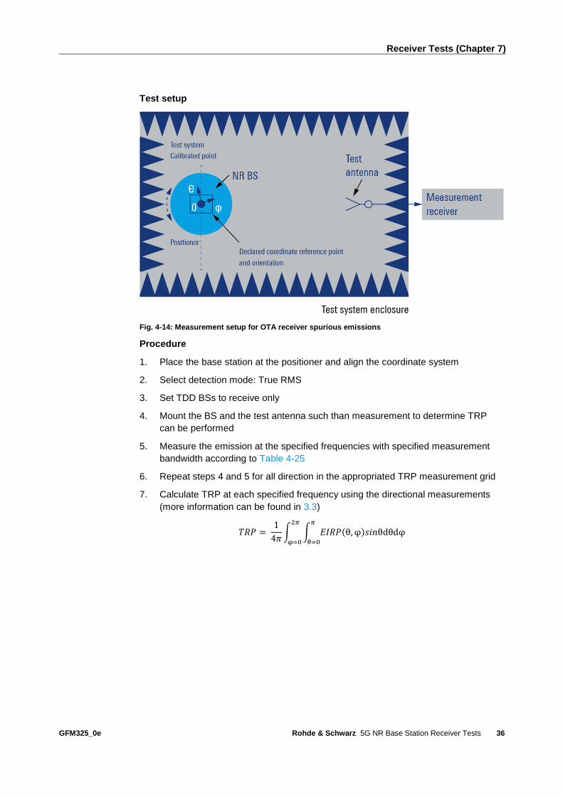
Test setup
Fig. 4-14: Measurement setup for OTA receiver spurious emissions
Procedure
1. Place the base station at the positioner and align the coordinate system
2. Select detection mode: True RMS
3. Set TDD BSs to receive only
4. Mount the BS and the test antenna such than measurement to determine TRP
can be performed
5. Measure the emission at the specified frequencies with specified measurement
bandwidth according to Table 4-25
6. Repeat steps 4 and 5 for all direction in the appropriated TRP measurement grid
7. Calculate TRP at each specified frequency using the directional measurements
(more information can be found in 3.3)
𝑇𝑅𝑃 = 1
4𝜋∫ ∫ 𝐸𝐼𝑅𝑃(θ, φ)𝑠𝑖𝑛θdθdφ
𝜋
θ=0
2𝜋
φ=0

Receiver Tests (Chapter 7)
GFM325_0e Rohde & Schwarz 5G NR Base Station Receiver Tests
37
4.7 OTA receiver intermodulation (7.8)
Intermodulation response rejection is a measure of the capability of the receiver unit to
receive a wanted signal on its assigned channel frequency in the presence of two
interfering signals which have a specific frequency relationship to the wanted signal.
Third and higher order mixing of the two interfering RF signals can produce an
interfering signal in the band of the desired channel. Interfering signals shall be a CW
signal and a 5G NR signal. [3]
Test setup
Fig. 4-15: Measurement setup for OTA receiver intermodulation
For generating the two interferers you can use the second channel of the SMW and an
external CW generator (e.g. SMF100A).
Procedure
1. Place the base station at the positioner and align the coordinate system
2. Align the base station with the test antenna in the declared direction to be tested
(all the power from the test antenna is captured by the BS)
3. Configure beam peak direction according to the declared reference beam
direction pair
4. Set the BS to transmit beams of the same operational band as the OSDD being
tested
5. Settings for the signal generators (according to Table 4-26 to Table 4-31)
(use the SMW IQ stream mapper and a hybrid combiner to sum all signals )
a) Set the SMW (channel A) to transmit the wanted Signal
b) Set the SMW (channel B) to transmit the 5G NR interfering signal
c) Set the CW Generator to transmit the CW signal
6. Measure the throughput for each supported polarization
7. Repeat the measurement for all measurement directions and supported
polarizations

Receiver Tests (Chapter 7)
GFM325_0e Rohde & Schwarz 5G NR Base Station Receiver Tests
38
4.7.1 General intermodulation
Fig. 4-16: Intermodulation
The throughput shall be ≥ 95% of the maximum throughput of the reference
measurement channel, with a wanted signal at the assigned channel frequency and
two interfering signals at the RIB with the conditions specified in the following tables.
Table 4-26: General intermodulation requirement for BS type 1-O
BS class Wanted Signal mean
power (dBm)
Mean power of interfering
signals (dBm)
Type of interfering
signal
Wide Area BS EISREFSENS + 6 dB -52 - ΔOTAREFSENS See Table 4-27
EISminSENS + 6 dB -52 - ΔminSENS
Medium Range BS EISREFSENS + 6 dB -47 - ΔOTAREFSENS
EISminSENS + 6 dB -47 - ΔminSENS
Local Area BS EISREFSENS + 6 dB -44 - ΔOTAREFSENS
EISminSENS + 6 dB -44 - ΔminSENS
Table 4-27: Interfering signals for intermodulation requirement (BS type 1-O)
BS channel
bandwidth of the
lowest/highest carrier
received (MHz)
Interfering signal center
frequency offset from the
lower/upper base station RF
Bandwidth edge (MHz)
Type of interfering signal
5 ±7.5 CW
±17.5 5MHz DFT-s-OFDM NR signal (Note 1)
10 ±7.45 CW
±17.5 5MHz DFT-s-OFDM NR signal (Note 1)
15 ±7.43 CW
±17.5 5MHz DFT-s-OFDM NR signal (Note 1)

Receiver Tests (Chapter 7)
GFM325_0e Rohde & Schwarz 5G NR Base Station Receiver Tests
39
20 ±7.38 CW
±17.5 5MHz DFT-s-OFDM NR signal (Note 1)
30 ±7.43 CW
±25 20 MHz DFT-s-OFDM NR signal (Note 1)
25 ±7.45 CW
±25 20MHz DFT-s-OFDM NR signal (Note 2)
40 ±7.45 CW
±25 20MHz DFT-s-OFDM NR signal (Note 2)
50 ±7.35 CW
±25 20MHz DFT-s-OFDM NR signal (Note 2)
60 ±7.49 CW
±25 20MHz DFT-s-OFDM NR signal (Note 2)
70 ±7.42 CW
±25 20 MHz DFT-s-OFDM NR signal (Note 2)
80 ±7.44 CW
±25 20MHz DFT-s-OFDM NR signal (Note 2)
90 ±25 CW
±7.43 20 MHz DFT-s-OFDM NR signal (Note 2)
100 ±7.45 CW
±25 20MHz DFT-s-OFDM NR signal (Note 2)
Note 1: For the 15 kHz subcarrier spacing, the number of RB is 25. For the 30 kHz
subcarrier spacing, the number of RB is 10.
Note 2: For the 15 kHz subcarrier spacing, the number of RB is 100. For the 30 kHz
subcarrier spacing, the number of RB is 50. For the 60 kHz subcarrier spacing, the
number of RB is 24.
Table 4-28: General intermodulation requirement BS type 2-O
BS channel bandwidth
of the lowest/highest
carrier received (MHz)
Mean power of interfering
signals (dBm)
Wanted signal mean
power (dBm)
Type of interfering
signal
50, 100, 200, 400 EISREFSENS_50M + 25 +
ΔFR2_REFSENS dB
EISREFSENS + 6dB see Table 4-29
Table 4-29: Interfering signals for intermodulation requirement (BS type 2-O)
BS channel bandwidth of
the lowest/highest carrier
received (MHz)
Interfering signal centre frequency
offset from the Base Station RF
Bandwidth edge (MHz)
Type of interfering signal
50 MHz ±7.5 CW
±40 50MHz DFT-s-OFDM NR signal
(Note)

Receiver Tests (Chapter 7)
GFM325_0e Rohde & Schwarz 5G NR Base Station Receiver Tests
40
100 MHz ±6.88 CW
±40 50MHz DFT-s-OFDM NR signal
(Note)
200 MHz ±5.64 CW
±40 50MHz DFT-s-OFDM NR signal
(Note)
400 MHz ±6.02 CW
±45 50MHz DFT-s-OFDM NR signal
(Note)
Note: For the 60 kHz subcarrier spacing, the number of RBs is 64. For the 120 kHz subcarrier spacing, the
number of RBs is 32.
4.7.2 Narrowband intermodulation
Fig. 4-17: Narrowband intermodulation
For each measured NR carrier, the throughput shall be ≥ 95% of the possible
maximum throughput of the reference measurement channel.
Table 4-30: Narrowband intermodulation performance requirement for BS type 1-O
BS class Wanted signal mean
power (dBm)
Interfering signal
mean power (dBm)
Type of interfering signal
Wide Area BS EISREFSENS + 6 dB -52 - ΔOTAREFSENS See Table 4-31
EISminSENS + 6 dB -52 - ΔminSENS
Medium Range BS EISREFSENS + 6 dB -47 - ΔOTAREFSENS

Receiver Tests (Chapter 7)
GFM325_0e Rohde & Schwarz 5G NR Base Station Receiver Tests
41
EISminSENS + 6 dB -47 - ΔminSENS
Local Area BS EISREFSENS + 6 dB -44 - ΔOTAREFSENS
EISminSENS + 6 dB -44 - ΔminSENS
Table 4-31: Interfering signals for narrowband intermodulation requirement for BS type 1-O
BS channel
bandwidth of the
lowest/highest
carrier received
(MHz)
Interfering RB center frequency
offset from the lower/upper Base
Station RF Bandwidth edge or
sub-block edge inside a sub-
block gap (kHz)
Type of interfering signal
5 ±360 CW
±1420 5MHz DFT-s-OFDM NR signal, 1 RB (Note 1)
10 ±325 CW
±1780 5MHz DFT-s-OFDM NR signal, 1 RB (Note 1)
15 ±380 CW
±1600 5MHz DFT-s-OFDM NR signal, 1 RB (Note 1)
20 ±345 CW
±1780 5MHz DFT-s-OFDM NR signal, 1 RB (Note 1)
25 ±325 CW
±1990 20MHz DFT-s-OFDM NR signal, 1 RB (Note 1)
30 ±320 CW
±1990 20MHz DFT-s-OFDM NR signal, 1 RB (Note 1)
40 ±310 CW
±2710 20MHz DFT-s-OFDM NR signal, 1 RB (Note 1)
50 ±330 CW
±3250 20MHz DFT-s-OFDM NR signal, 1 RB (Note 1)
60 ±350 CW
±3790 20MHz DFT-s-OFDM NR signal, 1 RB (Note 1)
70 ±400 CW
±4870 20MHz DFT-s-OFDM NR signal, 1 RB (Note 1)
80 ±390 CW
±4870 20MHz DFT-s-OFDM NR signal, 1 RB (Note 1)
90 ±340 CW
±5770 20MHz DFT-s-OFDM NR signal, 1 RB (Note 1)
100 ±340 CW
±5770 20MHz DFT-s-OFDM NR signal, 1 RB (Note 1)
Note 1: Interfering signal consisting of one resource block positioned at the stated
offset, the BS channel bandwidth of the interfering signal is located adjacently to the
lower/upper base station RF bandwidth edge.

Receiver Tests (Chapter 7)
GFM325_0e Rohde & Schwarz 5G NR Base Station Receiver Tests
42
4.8 OTA in-channel selectivity (7.9)
In-channel selectivity (ICS) is a measure of the receiver ability to receive a wanted
signal at its assigned resource block locations in the presence of an interfering signal
received at a larger power spectral density. The purpose of this test is to verify the BS
receiver ability to suppress the IQ leakage. [3]
The throughput shall be ≥ 95% of the maximum throughput of the reference
measurement channel
Fig. 4-18: In-channel selectivity
Table 4-32: Wide area BS in channel selectivity (BS type 1-O)
BS
channel
BW
(MHz)
SCS
(kHz)
Reference
measurement
channel
Wanted signal mean power (dBm) Interfering
signal mean
power (dBm)
Type of
interfering
signal f ≤ 3.0 GHz 3.0 GHz < f
≤ 4.2 GHz
4.2 GHz < f
≤ 6.0 GHz
5 15 G-FR1-A1-7 -98.9-
ΔminSENS
-98.5-
ΔminSENS
-98.2-
ΔminSENS
-81.4 - ΔminSENS DFT-s-OFDM
NR signal,
15 kHz SCS,
10 RBs
10, 15,
20, 25,
30
15 G-FR1-A1-1 -97-ΔminSENS -96.6-
ΔminSENS
-96.3-
ΔminSENS
-77.4 - ΔminSENS DFT-s-OFDM
NR signal,
15 kHz SCS,
25 RBs
40, 50 15 G-FR1-A1-4 -90.6-
ΔminSENS
-90.2-
ΔminSENS
-89.9-
ΔminSENS
-71.4 - ΔminSENS DFT-s-OFDM
NR signal,
15 kHz SCS,
100 RBs
5 30 G-FR1-A1-8 -99.6-
ΔminSENS
-99.2-
ΔminSENS
-98.9-
ΔminSENS
-81.4 - ΔminSENS DFT-s-OFDM
NR signal,
30 kHz SCS,
5 RBs

Receiver Tests (Chapter 7)
GFM325_0e Rohde & Schwarz 5G NR Base Station Receiver Tests
43
10, 15,
20, 25,
30
30 G-FR1-A1-2 -97.1-
ΔminSENS
-96.7-
ΔminSENS
-96.4-
ΔminSENS
-78.4 - ΔminSENS DFT-s-OFDM
NR signal,
30 kHz SCS,
10 RBs
40, 50,
60, 70,
80, 90,
100
30 G-FR1-A1-5 -90.9-
ΔminSENS
-90.5-
ΔminSENS
-90.2-
ΔminSENS
-71.4 - ΔminSENS DFT-s-OFDM
NR signal,
30 kHz SCS,
50 RBs
10, 15,
20, 25,
30
60 G-FR1-A1-9 -96.5-
ΔminSENS
-96.1-
ΔminSENS
-95.8-
ΔminSENS
-78.4 - ΔminSENS DFT-s-OFDM
NR signal,
60 kHz SCS,
5 RBs
40, 50,
60, 70,
80, 90,
100
60 G-FR1-A1-6 -91-ΔminSENS -90.6-
ΔminSENS
-90.3-
ΔminSENS
-71.6 - ΔminSENS DFT-s-OFDM
NR signal,
60 kHz SCS,
24 RBs
Table 4-33: Medium range BS in-channel selectivity (BS type 1-O)
BS
channel
BW
(MHz)
SCS
(kHz)
Reference
measurement
channel
Wanted signal mean power (dBm) Interfering
signal mean
power (dBm)
Type of
interfering
signal f ≤ 3.0 GHz 3.0 GHz < f
≤ 4.2 GHz
4.2 GHz < f
≤ 6.0 GHz
5 15 G-FR1-A1-7 -93.9-
ΔminSENS
-93.5-
ΔminSENS
-93.2-
ΔminSENS
-76.4 - ΔminSENS DFT-s-
OFDM NR
signal,
15 kHz
SCS, 10
RBs
10, 15,
20, 25,
30
15 G-FR1-A1-1 -92-ΔminSENS -91.6-
ΔminSENS
-91.3-
ΔminSENS
-72.4 - ΔminSENS DFT-s-
OFDM NR
signal,
15 kHz
SCS, 25
RBs
40, 50 15 G-FR1-A1-4 -85.6-
ΔminSENS
-85.2-
ΔminSENS
-84.9-
ΔminSENS
-66.4 - ΔminSENS DFT-s-
OFDM NR
signal,
15 kHz
SCS, 100
RBs
5 30 G-FR1-A1-8 -94.6-
ΔminSENS
-94.2-
ΔminSENS
-93.9-
ΔminSENS
-76.4 - ΔminSENS DFT-s-
OFDM NR
signal,
30 kHz
SCS, 5 RBs
10, 15,
20, 25,
30
30 G-FR1-A1-2 -92.1-
ΔminSENS
-91.7-
ΔminSENS
-91.4-
ΔminSENS
-73.4 - ΔminSENS DFT-s-
OFDM NR
signal,
30 kHz
SCS, 10
RBs

Receiver Tests (Chapter 7)
GFM325_0e Rohde & Schwarz 5G NR Base Station Receiver Tests
44
40, 50,
60, 70,
80, 90,
100
30 G-FR1-A1-5 -85.9-
ΔminSENS
-85.5-
ΔminSENS
-85.2-
ΔminSENS
-66.4 - ΔminSENS DFT-s-
OFDM NR
signal,
30 kHz
SCS, 50
RBs
10, 15,
20, 25,
30
60 G-FR1-A1-9 -91.5-
ΔminSENS
-91.1-
ΔminSENS
-90.8-
ΔminSENS
-73.4 - ΔminSENS DFT-s-
OFDM NR
signal,
60 kHz
SCS, 5 RBs
40, 50,
60, 70,
80, 90,
100
60 G-FR1-A1-6 -86-ΔminSENS -85.6-
ΔminSENS
-85.3-
ΔminSENS
-66.6 - ΔminSENS DFT-s-
OFDM NR
signal,
60 kHz
SCS, 24
RBs
Table 4-34: Local area BS in-channel selectivity (BS type 1-O)
BS
channel
BW
(MHz)
SCS
(kHz)
Reference
measurement
channel
Wanted signal mean power (dBm) Interfering
signal mean
power (dBm)
Type of
interfering
signal f ≤ 3.0
GHz
3.0 GHz < f ≤
4.2 GHz
4.2 GHz < f
≤ 6.0 GHz
5 15 G-FR1-A1-7 -90.9-
ΔminSENS
-90.5-ΔminSENS -90.2-
ΔminSENS
-73.4 - ΔminSENS DFT-s-
OFDM NR
signal,
15 kHz
SCS, 10
RBs
10, 15,
20, 25,
30
15 G-FR1-A1-1 -89-
ΔminSENS
-88.6-ΔminSENS -88.3-
ΔminSENS
-69.4 - ΔminSENS DFT-s-
OFDM NR
signal,
15 kHz
SCS, 25
RBs
40, 50 15 G-FR1-A1-4 -82.6-
ΔminSENS
-82.2-ΔminSENS -81.9-
ΔminSENS
-63.4 - ΔminSENS DFT-s-
OFDM NR
signal,
15 kHz
SCS, 100
RBs
5 30 G-FR1-A1-8 -91.6-
ΔminSENS
-91.2-ΔminSENS -90.9-
ΔminSENS
-73.4 - ΔminSENS DFT-s- NR
signal,
30 kHz
SCS, 5 RBs
10, 15,
20, 25,
30
30 G-FR1-A1-2 -89.1-
ΔminSENS
-88.7-ΔminSENS -88.4-
ΔminSENS
-70.4 - ΔminSENS DFT-s-
OFDM NR
signal,
30 kHz
SCS, 10
RBs

Receiver Tests (Chapter 7)
GFM325_0e Rohde & Schwarz 5G NR Base Station Receiver Tests
45
40, 50,
60, 70,
80, 90,
100
30 G-FR1-A1-5 -82.9-
ΔminSENS
-82.5-ΔminSENS -82.2-
ΔminSENS
-63.4 - ΔminSENS DFT-s-
OFDM NR
signal,
30 kHz
SCS, 50
RBs
10, 15,
20, 25,
30
60 G-FR1-A1-9 -88.5-
ΔminSENS
-88.1-ΔminSENS -87.8-
ΔminSENS
-70.4 - ΔminSENS DFT-s-
OFDM NR
signal,
60 kHz
SCS, 5 RBs
40, 50,
60, 70,
80, 90,
100
60 G-FR1-A1-6 -83-
ΔminSENS
-82.6-ΔminSENS -82.3-
ΔminSENS
-63.6 - ΔminSENS DFT-s-
OFDM NR
signal,
60 kHz
SCS, 24
RBs
Table 4-35: OTA in-channel selectivity requirement (BS type 2-O)
BS
channel
BW (MHz)
SCS
(kHz)
Reference
measurement
channel
Wanted signal mean
power (dBm)
Interfering signal
mean power (dBm)
Type of interfering
signal
50 60 G-FR2-A1-4 EISREFSENS_50M + 3.4 +
ΔFR2_REFSENS
EISREFSENS_50M + 10 +
ΔFR2_REFSENS
DFT-s-OFDM NR
signal, 60 kHz SCS,
32 RBs
100, 200 60 G-FR2-A1-1 EISREFSENS_50M + 6.4 +
ΔFR2_REFSENS
EISREFSENS_50M + 13 +
ΔFR2_REFSENS
DFT-s-OFDM NR
signal, 60 kHz SCS,
64 RBs
50 120 G-FR2-A1-5 EISREFSENS_50M + 3.4 +
ΔFR2_REFSENS
EISREFSENS_50M + 10 +
ΔFR2_REFSENS
DFT-s-OFDM NR
signal, 120 kHz
SCS, 16 RBs
100, 200,
400
120 G-FR2-A1-2 EISREFSENS_50M + 6.4 +
ΔFR2_REFSENS
EISREFSENS_50M + 13 +
ΔFR2_REFSENS
DFT-s-OFDM NR
signal, 120 kHz
SCS, 32 RBs
Test setup
Fig. 4-19: Measurement setup for OTA in-channel selectivity

Receiver Tests (Chapter 7)
GFM325_0e Rohde & Schwarz 5G NR Base Station Receiver Tests
46
Procedure
1. Place the base station at the positioner and align the coordinate system
2. Align the base station with the test antenna in the declared direction to be tested
3. Align the BS to that the wanted signal and interferer signal is polarization matched
with test antenna
4. Configure beam peak direction according to the declared reference beam
direction pair
5. Set the BS to transmit beams of the same operational band as the OTA
REFSENS RoAoA or OSDD being tested
For each supported NR channel BW:
6. SMW Settings (use a hybrid combiner to sum all signals)
a) Transmit 5G NR signal according to Table 4-32 to Table 4-35
b) Settings for the interfering signal (it is provided in the same baseband block
and path) according to Table 4-32 to Table 4-35
7. Measure throughput for each supported polarization
8. Repeat the measurement with the wanted signal on the other side of the FC, and
the interfering signal at opposite side of the FC and adjacent to the wanted signal.
9. Repeat the measurement for all measurement directions and supported
polarizations

Literature
GFM325_0e Rohde & Schwarz 5G NR Base Station Receiver Tests
47
5 Literature
[1] Rohde & Schwarz, 5G NR Technology Introduction, March 2019
[2] 3GPP Technical Specification Group Radio Access Network, NR Base station
conformance testing, Part 1: Radiated conformance testing, Release 16
3GPP TS 38.141-1, V16.1.0, October 2019
[3] 3GPP Technical Specification Group Radio Access Network, NR Base station
conformance testing, Part 2: Radiated conformance testing, Release 16
3GPP TS 38.141-2, V16.1.0, October 2019
[4] Rohde & Schwarz, R&S®SMW-K544 User-Defined Frequency Response
Correction - User manual, 2019
[5] Rohde & Schwarz, R&S®FSW Signal and Spectrum Analyzer - User Manual
[6] Rohde & Schwarz, "White paper - Demystifying over-the-air (OTA) testing -
important antenna parameters, test system setup and calibration", May 2019
Available: https://www.rohde-schwarz.com/de/loesungen/test-and-
measurement/wireless-communication/wireless-5g-and-cellular/5g-test-and-
measurement/ota-white-paper_251028.html
[7] Rohde & Schwarz, "R&S®ATS1800C CATR product brochure"
Available: https://scdn.rohde-
schwarz.com/ur/pws/dl_downloads/dl_common_library/dl_brochures_and_datash
eets/pdf_1/ATS1800C_pro-fly_en_3608-1298-32_v0100.pdf
[8] Rohde & Schwarz, R&S®ATS1800C - User manual, 2019
[9] 3GPP Technical Specification Group Radio Access Network, Base Station radio
transmission and reception, Release 16
3GPP TS38.104, V16.1.0, October 2019

Ordering Information
GFM325_0e Rohde & Schwarz 5G NR Base Station Receiver Tests
48
6 Ordering Information
Designation Type Order No.
Compact antenna test range (CATR)
OTA test system
R&S®ATS1800C
1534.1800K02
Vector signal generator R&S®SMW200A 1412.0000.02
5G-NR (software option) R&S®SMW-K144 1414.4990.02
Additive White Gaussian Noise (software option) R&S®SMW-K62 1413.3484.02
User-defined frequency response correction (software option) R&S®SMW-K544 1414.3707.02
IQ Upconverter (58.32 GHz to 64.80 GHz) R&S®SZU100A 1425.3003.02
Microwave signal generator (CW generator) R&S®SMF100A 1167.0000.02
Frequency Multiplier (50 GHz to 75 GHz) R&S®SMZ 1417.4004.02
Signal and spectrum analyzer R&S®FSW67 1331.5003.67
User defined frequency correction by SnP file (software option) R&S®FSW-K544 1338.2716.02

Appendix
GFM325_0e Rohde & Schwarz 5G NR Base Station Receiver Tests
49
Appendix
A Test requirements
A.1 OTA dynamic range (7.4)
Table 6-1: Wide area BS dynamic range
BS
channel
bandwidth
(MHz)
SCS
(kHz)
Reference
measurement
channel
Wanted signal mean power (dBm) Interfering
sig. mean
pow. (dBm) /
BWConfig
Type of
interfer-
ing
signal
f ≤ 3.0 GHz 3.0 GHz < f
≤ 4.2 GHz
4.2 GHz < f
≤ 6.0 GHz
5 15 G-FR1-A2-1 -70.4 –
ΔOTAREFSENS
-70.4 –
ΔOTAREFSENS
-70.4 –
ΔOTAREFSENS
-82.5 –
ΔOTAREFSENS
AWGN
30 G-FR1-A2-2 -71.1 –
ΔOTAREFSENS
-71.1 –
ΔOTAREFSENS
-71.1 –
ΔOTAREFSENS
10 15 G-FR1-A2-1 -70.4 –
ΔOTAREFSENS
-70.4 –
ΔOTAREFSENS
-70.4 –
ΔOTAREFSENS
-79.3 –
ΔOTAREFSENS
AWGN
30 G-FR1-A2-2 -71.1 –
ΔOTAREFSENS
-71.1 –
ΔOTAREFSENS
-71.1 –
ΔOTAREFSENS
60 G-FR1-A2-3 -68.1 –
ΔOTAREFSENS
-68.1 –
ΔOTAREFSENS
-68.1 –
ΔOTAREFSENS
15 15 G-FR1-A2-1 -70.4 –
ΔOTAREFSENS
-70.4 –
ΔOTAREFSENS
-70.4 –
ΔOTAREFSENS
-77.5 –
ΔOTAREFSENS
AWGN
30 G-FR1-A2-2 -71.1 –
ΔOTAREFSENS
-71.1 –
ΔOTAREFSENS
-71.1 –
ΔOTAREFSENS
60 G-FR1-A2-3 -68.1 –
ΔOTAREFSENS
-68.1 –
ΔOTAREFSENS
-68.1 –
ΔOTAREFSENS
20 15 G-FR1-A2-4 -64.2 –
ΔOTAREFSENS
-64.2 –
ΔOTAREFSENS
-64.2 –
ΔOTAREFSENS
-76.2 –
ΔOTAREFSENS
AWGN
30 G-FR1-A2-5 -64.2 –
ΔOTAREFSENS
-64.2 –
ΔOTAREFSENS
-64.2 –
ΔOTAREFSENS
60 G-FR1-A2-6 -64.5 –
ΔOTAREFSENS
-64.5 –
ΔOTAREFSENS
-64.5 –
ΔOTAREFSENS
25 15 G-FR1-A2-4 -64.2 –
ΔOTAREFSENS
-64.2 –
ΔOTAREFSENS
-64.2 –
ΔOTAREFSENS
-75.2 –
ΔOTAREFSENS
AWGN
30 G-FR1-A2-5 -64.2 –
ΔOTAREFSENS
-64.2 –
ΔOTAREFSENS
-64.2 –
ΔOTAREFSENS
60 G-FR1-A2-6 -64.5 –
ΔOTAREFSENS
-64.5 –
ΔOTAREFSENS
-64.5 –
ΔOTAREFSENS
30 15 G-FR1-A2-4 -64.2 –
ΔOTAREFSENS
-64.2 –
ΔOTAREFSENS
-64.2 –
ΔOTAREFSENS
-74.4 –
ΔOTAREFSENS
AWGN
30 G-FR1-A2-5 -64.2 –
ΔOTAREFSENS
-64.2 –
ΔOTAREFSENS
-64.2 –
ΔOTAREFSENS

Appendix
GFM325_0e Rohde & Schwarz 5G NR Base Station Receiver Tests
50
60 G-FR1-A2-6 -64.5 –
ΔOTAREFSENS
-64.5 –
ΔOTAREFSENS
-64.5 –
ΔOTAREFSENS
40 15 G-FR1-A2-4 -64.2 –
ΔOTAREFSENS
-64.2 –
ΔOTAREFSENS
-64.2 –
ΔOTAREFSENS
-73.1 –
ΔOTAREFSENS
AWGN
30 G-FR1-A2-5 -64.2 –
ΔOTAREFSENS
-64.2 –
ΔOTAREFSENS
-64.2 –
ΔOTAREFSENS
60 G-FR1-A2-6 -64.5 –
ΔOTAREFSENS
-64.5 –
ΔOTAREFSENS
-64.5 –
ΔOTAREFSENS
50 15 G-FR1-A2-4 -64.2 –
ΔOTAREFSENS
-64.2 –
ΔOTAREFSENS
-64.2 –
ΔOTAREFSENS
-72.2 –
ΔOTAREFSENS
AWGN
30 G-FR1-A2-5 -64.2 –
ΔOTAREFSENS
-64.2 –
ΔOTAREFSENS
-64.2 –
ΔOTAREFSENS
60 G-FR1-A2-6 -64.5 –
ΔOTAREFSENS
-64.5 –
ΔOTAREFSENS
-64.5 –
ΔOTAREFSENS
60 30 G-FR1-A2-5 -64.2 –
ΔOTAREFSENS
-64.2 –
ΔOTAREFSENS
-64.2 –
ΔOTAREFSENS
-71.4 –
ΔOTAREFSENS
AWGNs
60 G-FR1-A2-6 -64.5 –
ΔOTAREFSENS
-64.5 –
ΔOTAREFSENS
-64.5 –
ΔOTAREFSENS
70 30 G-FR1-A2-5 -64.2 –
ΔOTAREFSENS
-64.2 –
ΔOTAREFSENS
-64.2 –
ΔOTAREFSENS
-70.8 –
ΔOTAREFSENS
AWGN
60 G-FR1-A2-6 -64.5 –
ΔOTAREFSENS
-64.5 –
ΔOTAREFSENS
-64.5 –
ΔOTAREFSENS
80 30 G-FR1-A2-5 -64.2 –
ΔOTAREFSENS
-64.2 –
ΔOTAREFSENS
-64.2 –
ΔOTAREFSENS
-70.1 –
ΔOTAREFSENS
AWGN
60 G-FR1-A2-6 -64.5 –
ΔOTAREFSENS
-64.5 –
ΔOTAREFSENS
-64.5 –
ΔOTAREFSENS
90 30 G-FR1-A2-5 -64.2 –
ΔOTAREFSENS
-64.2 –
ΔOTAREFSENS
-64.2 –
ΔOTAREFSENS
-69.6 –
ΔOTAREFSENS
AWGN
60 G-FR1-A2-6 -64.5 –
ΔOTAREFSENS
-64.5 –
ΔOTAREFSENS
-64.5 –
ΔOTAREFSENS
100 30 G-FR1-A2-5 -64.2 –
ΔOTAREFSENS
-64.2 –
ΔOTAREFSENS
-64.2 –
ΔOTAREFSENS
-69.1 –
ΔOTAREFSENS
AWGN
60 G-FR1-A2-6 -64.5 –
ΔOTAREFSENS
-64.5 –
ΔOTAREFSENS
-64.5 –
ΔOTAREFSENS
Table 6-2: Medium range BS dynamic range
BS
channel
bandwidth
(MHz)
SCS
(kHz)
Reference
measurement
channel
Wanted signal mean power (dBm) Interfering
signal mean
power (dBm)
/ BWConfig
Type of
interfer-
ing
signal
f ≤ 3.0 GHz 3.0 GHz < f
≤ 4.2 GHz
4.2 GHz < f
≤ 6.0 GHz
5 15 G-FR1-A2-1 -65.4 –
ΔOTAREFSENS
-65.4 –
ΔOTAREFSENS
-65.4 –
ΔOTAREFSENS
-77.5 –
ΔOTAREFSENS
AWGN
30 G-FR1-A2-2 -66.1 –
ΔOTAREFSENS
-66.1 –
ΔOTAREFSENS
-66.1 –
ΔOTAREFSENS
10 15 G-FR1-A2-1 -65.4 –
ΔOTAREFSENS
-65.4 –
ΔOTAREFSENS
-65.4 –
ΔOTAREFSENS
-74.3 –
ΔOTAREFSENS
AWGN
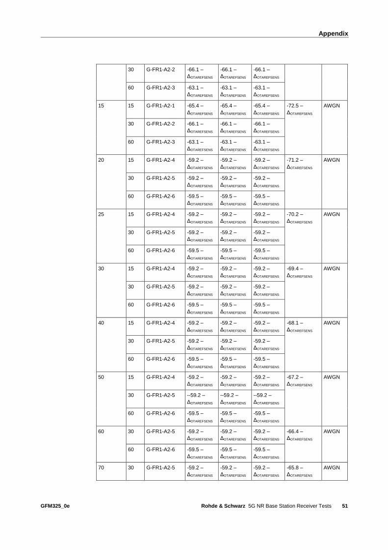
Appendix
GFM325_0e Rohde & Schwarz 5G NR Base Station Receiver Tests
51
30 G-FR1-A2-2 -66.1 –
ΔOTAREFSENS
-66.1 –
ΔOTAREFSENS
-66.1 –
ΔOTAREFSENS
60 G-FR1-A2-3 -63.1 –
ΔOTAREFSENS
-63.1 –
ΔOTAREFSENS
-63.1 –
ΔOTAREFSENS
15 15 G-FR1-A2-1 -65.4 –
ΔOTAREFSENS
-65.4 –
ΔOTAREFSENS
-65.4 –
ΔOTAREFSENS
-72.5 –
ΔOTAREFSENS
AWGN
30 G-FR1-A2-2 -66.1 –
ΔOTAREFSENS
-66.1 –
ΔOTAREFSENS
-66.1 –
ΔOTAREFSENS
60 G-FR1-A2-3 -63.1 –
ΔOTAREFSENS
-63.1 –
ΔOTAREFSENS
-63.1 –
ΔOTAREFSENS
20 15 G-FR1-A2-4 -59.2 –
ΔOTAREFSENS
-59.2 –
ΔOTAREFSENS
-59.2 –
ΔOTAREFSENS
-71.2 –
ΔOTAREFSENS
AWGN
30 G-FR1-A2-5 -59.2 –
ΔOTAREFSENS
-59.2 –
ΔOTAREFSENS
-59.2 –
ΔOTAREFSENS
60 G-FR1-A2-6 -59.5 –
ΔOTAREFSENS
-59.5 –
ΔOTAREFSENS
-59.5 –
ΔOTAREFSENS
25 15 G-FR1-A2-4 -59.2 –
ΔOTAREFSENS
-59.2 –
ΔOTAREFSENS
-59.2 –
ΔOTAREFSENS
-70.2 –
ΔOTAREFSENS
AWGN
30 G-FR1-A2-5 -59.2 –
ΔOTAREFSENS
-59.2 –
ΔOTAREFSENS
-59.2 –
ΔOTAREFSENS
60 G-FR1-A2-6 -59.5 –
ΔOTAREFSENS
-59.5 –
ΔOTAREFSENS
-59.5 –
ΔOTAREFSENS
30 15 G-FR1-A2-4 -59.2 –
ΔOTAREFSENS
-59.2 –
ΔOTAREFSENS
-59.2 –
ΔOTAREFSENS
-69.4 –
ΔOTAREFSENS
AWGN
30 G-FR1-A2-5 -59.2 –
ΔOTAREFSENS
-59.2 –
ΔOTAREFSENS
-59.2 –
ΔOTAREFSENS
60 G-FR1-A2-6 -59.5 –
ΔOTAREFSENS
-59.5 –
ΔOTAREFSENS
-59.5 –
ΔOTAREFSENS
40 15 G-FR1-A2-4 -59.2 –
ΔOTAREFSENS
-59.2 –
ΔOTAREFSENS
-59.2 –
ΔOTAREFSENS
-68.1 –
ΔOTAREFSENS
AWGN
30 G-FR1-A2-5 -59.2 –
ΔOTAREFSENS
-59.2 –
ΔOTAREFSENS
-59.2 –
ΔOTAREFSENS
60 G-FR1-A2-6 -59.5 –
ΔOTAREFSENS
-59.5 –
ΔOTAREFSENS
-59.5 –
ΔOTAREFSENS
50 15 G-FR1-A2-4 -59.2 –
ΔOTAREFSENS
-59.2 –
ΔOTAREFSENS
-59.2 –
ΔOTAREFSENS
-67.2 –
ΔOTAREFSENS
AWGN
30 G-FR1-A2-5 --59.2 –
ΔOTAREFSENS
--59.2 –
ΔOTAREFSENS
--59.2 –
ΔOTAREFSENS
60 G-FR1-A2-6 -59.5 –
ΔOTAREFSENS
-59.5 –
ΔOTAREFSENS
-59.5 –
ΔOTAREFSENS
60 30 G-FR1-A2-5 -59.2 –
ΔOTAREFSENS
-59.2 –
ΔOTAREFSENS
-59.2 –
ΔOTAREFSENS
-66.4 –
ΔOTAREFSENS
AWGN
60 G-FR1-A2-6 -59.5 –
ΔOTAREFSENS
-59.5 –
ΔOTAREFSENS
-59.5 –
ΔOTAREFSENS
70 30 G-FR1-A2-5 -59.2 –
ΔOTAREFSENS
-59.2 –
ΔOTAREFSENS
-59.2 –
ΔOTAREFSENS
-65.8 –
ΔOTAREFSENS
AWGN

Appendix
GFM325_0e Rohde & Schwarz 5G NR Base Station Receiver Tests
52
60 G-FR1-A2-6 -59.5 –
ΔOTAREFSENS
-59.5 –
ΔOTAREFSENS
-59.5 –
ΔOTAREFSENS
80 30 G-FR1-A2-5 -59.2 –
ΔOTAREFSENS
-59.2 –
ΔOTAREFSENS
-59.2 –
ΔOTAREFSENS
-65.1 –
ΔOTAREFSENS
AWGN
60 G-FR1-A2-6 -59.5 –
ΔOTAREFSENS
-59.5 –
ΔOTAREFSENS
-59.5 –
ΔOTAREFSENS
90 30 G-FR1-A2-5 -59.2 –
ΔOTAREFSENS
-59.2 –
ΔOTAREFSENS
-59.2 –
ΔOTAREFSENS
-64.6 –
ΔOTAREFSENS
AWGN
60 G-FR1-A2-6 -59.5 –
ΔOTAREFSENS
-59.5 –
ΔOTAREFSENS
-59.5 –
ΔOTAREFSENS
100 30 G-FR1-A2-5 -59.2 –
ΔOTAREFSENS
-59.2 –
ΔOTAREFSENS
-59.2 –
ΔOTAREFSENS
-64.1 –
ΔOTAREFSENS
AWGN
60 G-FR1-A2-6 -59.5 –
ΔOTAREFSENS
-59.5 –
ΔOTAREFSENS
-59.5 –
ΔOTAREFSENS
Table 6-3: Local area BS dynamic range
BS channel
bandwidth
(MHz)
SCS
(kHz)
Reference
measure-
ment
channel
Wanted signal mean power (dBm) Interfering
signal mean
power (dBm)
/ BWConfig
Type of
interfer-
ing signal f ≤ 3.0 GHz 3.0 GHz < f
≤ 4.2 GHz
4.2 GHz < f
≤ 6.0 GHz
5 15 G-FR1-A2-1 -62.4 –
ΔOTAREFSENS
-62.4 –
ΔOTAREFSENS
-62.4 –
ΔOTAREFSENS
-74.5 –
ΔOTAREFSENS
AWGN
30 G-FR1-A2-2 -64.1 –
ΔOTAREFSENS
-64.1 –
ΔOTAREFSENS
-64.1 –
ΔOTAREFSENS
10 15 G-FR1-A2-1 -62.4 –
ΔOTAREFSENS
-62.4 –
ΔOTAREFSENS
-62.4 –
ΔOTAREFSENS
-71.3 –
ΔOTAREFSENS
AWGN
30 G-FR1-A2-2 -64.1 –
ΔOTAREFSENS
-64.1 –
ΔOTAREFSENS
-64.1 –
ΔOTAREFSENS
60 G-FR1-A2-3 -60.1 –
ΔOTAREFSENS
-60.1 –
ΔOTAREFSENS
-60.1 –
ΔOTAREFSENS
15 15 G-FR1-A2-1 -62.4 –
ΔOTAREFSENS
-62.4 –
ΔOTAREFSENS
-62.4 –
ΔOTAREFSENS
-69.5 –
ΔOTAREFSENS
AWGN
30 G-FR1-A2-2 -64.1 –
ΔOTAREFSENS
-64.1 –
ΔOTAREFSENS
-64.1 –
ΔOTAREFSENS
60 G-FR1-A2-3 -60.1 –
ΔOTAREFSENS
-60.1 –
ΔOTAREFSENS
-60.1 –
ΔOTAREFSENS
20 15 G-FR1-A2-4 -56.2 –
ΔOTAREFSENS
-56.2 –
ΔOTAREFSENS
-56.2 –
ΔOTAREFSENS
-68.2 –
ΔOTAREFSENS
AWGN
30 G-FR1-A2-5 -56.2 –
ΔOTAREFSENS
-56.2 –
ΔOTAREFSENS
-56.2 –
ΔOTAREFSENS
60 G-FR1-A2-6 -56.5 –
ΔOTAREFSENS
-56.5 –
ΔOTAREFSENS
-56.5 –
ΔOTAREFSENS
25 15 G-FR1-A2-4 -56.2 –
ΔOTAREFSENS
-56.2 –
ΔOTAREFSENS
-56.2 –
ΔOTAREFSENS
-67.2 –
ΔOTAREFSENS
AWGN

Appendix
GFM325_0e Rohde & Schwarz 5G NR Base Station Receiver Tests
53
30 G-FR1-A2-5 -56.2 –
ΔOTAREFSENS
-56.2 –
ΔOTAREFSENS
-56.2 –
ΔOTAREFSENS
60 G-FR1-A2-6 -56.5 –
ΔOTAREFSENS
-56.5 –
ΔOTAREFSENS
-56.5 –
ΔOTAREFSENS
30 15 G-FR1-A2-4 -56.2 –
ΔOTAREFSENS
-56.2 –
ΔOTAREFSENS
-56.2 –
ΔOTAREFSENS
-66.4 –
ΔOTAREFSENS
AWGN
30 G-FR1-A2-5 -56.2 –
ΔOTAREFSENS
-56.2 –
ΔOTAREFSENS
-56.2 –
ΔOTAREFSENS
60 G-FR1-A2-6 -56.5 –
ΔOTAREFSENS
-56.5 –
ΔOTAREFSENS
-56.5 –
ΔOTAREFSENS
40 15 G-FR1-A2-4 -56.2 –
ΔOTAREFSENS
-56.2 –
ΔOTAREFSENS
-56.2 –
ΔOTAREFSENS
-65.1 –
ΔOTAREFSENS
AWGN
30 G-FR1-A2-5 -56.2 –
ΔOTAREFSENS
-56.2 –
ΔOTAREFSENS
-56.2 –
ΔOTAREFSENS
60 G-FR1-A2-6 -56.5 –
ΔOTAREFSENS
-56.5 –
ΔOTAREFSENS
-56.5 –
ΔOTAREFSENS
50 15 G-FR1-A2-4 -56.2 –
ΔOTAREFSENS
-56.2 –
ΔOTAREFSENS
-56.2 –
ΔOTAREFSENS
-64.2 –
ΔOTAREFSENS
AWGN
30 G-FR1-A2-5 -56.2 –
ΔOTAREFSENS
-56.2 –
ΔOTAREFSENS
-56.2 –
ΔOTAREFSENS
60 G-FR1-A2-6 -56.5 –
ΔOTAREFSENS
-56.5 –
ΔOTAREFSENS
-56.5 –
ΔOTAREFSENS
60 30 G-FR1-A2-5 -56.2 –
ΔOTAREFSENS
-56.2 –
ΔOTAREFSENS
-56.2 –
ΔOTAREFSENS
-63.4 –
ΔOTAREFSENS
AWGN
60 G-FR1-A2-6 -56.5 –
ΔOTAREFSENS
-56.5 –
ΔOTAREFSENS
-56.5 –
ΔOTAREFSENS
70 30 G-FR1-A2-5 -56.2 –
ΔOTAREFSENS
-56.2 –
ΔOTAREFSENS
-56.2 –
ΔOTAREFSENS
-62.8 –
ΔOTAREFSENS
AWGN
60 G-FR1-A2-6 -56.5 –
ΔOTAREFSENS
-56.5 –
ΔOTAREFSENS
-56.5 –
ΔOTAREFSENS
80 30 G-FR1-A2-5 -56.2 –
ΔOTAREFSENS
-56.2 –
ΔOTAREFSENS
-56.2 –
ΔOTAREFSENS
-62.1 –
ΔOTAREFSENS
AWGN
60 G-FR1-A2-6 -56.5 –
ΔOTAREFSENS
-56.5 –
ΔOTAREFSENS
-56.5 –
ΔOTAREFSENS
90 30 G-FR1-A2-5 -56.2 –
ΔOTAREFSENS
-56.2 –
ΔOTAREFSENS
-56.2 –
ΔOTAREFSENS
-61.6 –
ΔOTAREFSENS
AWGN
60 G-FR1-A2-6 -56.5 –
ΔOTAREFSENS
-56.5 –
ΔOTAREFSENS
-56.5 –
ΔOTAREFSENS
100 30 G-FR1-A2-5 -56.2 –
ΔOTAREFSENS
-56.2 –
ΔOTAREFSENS
-56.2 –
ΔOTAREFSENS
-61.1 –
ΔOTAREFSENS
AWGN
60 G-FR1-A2-6 -56.5 –
ΔOTAREFSENS
-56.5 –
ΔOTAREFSENS
-56.5 –
ΔOTAREFSENS

Glossary
GFM325_0e Rohde & Schwarz 5G NR Base Station Receiver Tests
54
Glossary
Abbreviation Description
AoA Angle of arrival
BS Base station
CATR Compact antenna test range
CLTA Colocation test antenna
DUT Device under test
EIRP Effective isotropic radiated power
EIS Equivalent isotropic sensitivity
OSDD OTA sensitivity directions declaration
REFSENS Reference sensitivity
RIB Radiated interface boundary
RoAoA Range of angles of arrival
TRP Total radiated power
TRP Total radiated power
UE User equipment

Rohde & Schwarz
The Rohde & Schwarz electronics group offers
innovative solutions in the following business fields:
test and measurement, broadcast and media, secure
communications, cybersecurity, radiomonitoring and
radiolocation. Founded more than 80 years ago, this
independent company has an extensive sales and
service network and is present in more than 70
countries.
The electronics group is among the world market
leaders in its established business fields. The
company is headquartered in Munich, Germany. It
also has regional headquarters in Singapore and
Columbia, Maryland, USA, to manage its operations
in these regions.
Regional contact
Europe, Africa, Middle East +49 89 4129 12345 [email protected] North America 1 888 TEST RSA (1 888 837 87 72) [email protected] Latin America +1 410 910 79 88 [email protected] Asia Pacific +65 65 13 04 88 [email protected]
China +86 800 810 82 28 |+86 400 650 58 96 [email protected]
This application note and the supplied programs
may only be used subject to the conditions of use
set forth in the download area of the Rohde &
Schwarz website.
Version GFM325_0e
R&S® is a registered trademark of Rohde & Schwarz GmbH & Co.
KG; Trade names are trademarks of the owners.
Rohde & Schwarz GmbH & Co. KG
Mühldorfstraße 15 | 81671 Munich, Germany
Phone + 49 89 4129 - 0 | Fax + 49 89 4129 – 13777
www.rohde-schwarz.com
PA
D-T
-M:
3573.7
380.0
2/0
3.0
0/E
N