applicability of the security control automation protocol .... applicability of scap to voip... ·...
TRANSCRIPT

Page 1 of 117
1
2
3
4
5
6
7
8
9
10
11
12
Applicability of the 13
Security Control Automation Protocol (SCAP) 14
to Voice over Internet Protocol (VoIP) Systems 15
Version 0.9 16
17

Page 2 of 117
1
2
3
4
5
This publication is for informational purposes and presents a view on how practical it could be to 6 use the Security Content Automation Protocol (defined in NIST Special Publication 800-126) to 7 an implemented Voice over Internet Protocol (VoIP) System. While a view of a hypothetical 8 security assessment of a generic implemented VoIP System is presented in this publication it is 9 presented just as a rough guide, is not a substitute for a rigorous security assessment on a 10 particular VoIP system or implementation. 11
Participation in the development of this publication does not represent an endorsement of 12 the content of this publication on the part of any specific individual, company, or 13 corporation. Any reference made to existing commercial products or services is not 14 intended as, and does not constitute, and endorsement or approval of such products or 15 services. 16
This publication is protected by copyright, all rights reserved. The scanning, uploading and 17 distribution of this book by electronic means, including the Internet, without the permission of 18 the Internet Security Alliance, is illegal and punishable by law. 19
If you wish to acquire printed copies of this publication, or distribute portions of this publication 20 in any media, please contact Internet Security Alliance by calling (703)907-7799. 21
22
© 2010 Internet Security Alliance. All rights reserved. 23
24
Page 3 of 117
1
2
3
4
5
Applicability of the 6
Security Control Automation Protocol (SCAP) 7
to Voice over Internet Protocol (VoIP) Systems 8
Version 0.9 9
10
11

Page 4 of 117
1
2
3
4
5
Board of Directors 6
Larry Clinton President, Internet Security Alliance
Ken Silva Chief Technology Office, Verisign
Ty Sagalow IS Alliance Board Chair, Executive Vice-President and Chief Innovation Officer, Zurich North America
Charlie Croom Vice President, Cyber Security Strategy, Lockheed Martin
Mike Hickey First Vice Board Chair VP, Government Affairs & National Security Policy, Verizon
Joe Buonomo President, Direct Computer Resources, Inc.
Dr. Sagar Vidyasagar Second vice Board Chair Executive VP, Advanced Technology, Tata Consultancy Services
Jeff Brown Director, Infrastructure Services and CISO Information Technology, Raytheon
Marc-Anthony Signorino Secretary/Treasurer Director of Technology Policy, National Association of Manufacturers
Lawrence Dobranski Leader, Advanced Security Solutions Research & Development Nortel
Bruno Mahlman Vice President, National Security, Perot Systems Corporation
Eric Guerrino Managing Director Systems and Technology, Bank of New York Mellon
Tim McKnight Vice President & Chief Information Security Officer, Northrup Grumman
Dr. Pradeep Kohsla Dean, School of Engineering and Computer Sciences, Co-Director – Cylab, Carnegie Mellon University
7

Page 5 of 117
WHAT IS THE INTERNET SECURITY ALLIANCE? 1
Virtually every corporation integrates use of the Internet into their business 2 plan. However, the use of the Internet also exposes corporations to continuing 3 and persistent threats, putting at risk corporate intellectual property, business 4 operations, and overall enterprise security. These risks confront any business, 5
as well as all of their respective suppliers, business partners and customers. 6
The Internet Security Alliance (ISAlliance) is a non-traditional trade association that serves to 7 understand, integrate and help manage the multi-dimensional and international issues that 8 operating in the Internet creates. The ISAlliance website is www.isalliance.org. 9
WHAT DOES THE INTERENT SECURITY ALLIANCE DO? 10
ISAlliance provides tangible benefits to its membership by creating cutting edge services and 11 applicable publications useful across the various industry sectors that use the Internet. 12 ISAlliance was conceived in conjunction with Carnegie Mellon University to integrate 13 technological issues with the membership’s pragmatic business concerns and align public policy 14 to facilitate business growth and resilience. 15
The ISAlliance provides a broad range of ongoing technological, business and policy services to 16 its membership, all of which can be reviewed in more detail at the ISAlliance web site. In 17 addition, the ISAlliance Board identifies a select set of priority projects each year for intensive 18 work. 19
This report is a new contribution to a continuing series of publications produced by ISAlliance 20 that address the substantive issues that arise at the intersections of business, law and information 21 security. Previous titles include: 22
Navigating Compliance and Security for Unified Communications 23
The Cyber Security Social Contract: A Twenty-First Century Model for Protecting and 24 Defending Critical Technology Systems and Infrastructure. 25
The Financial Impact of Cyber Risk: 50 Questions Every CFO Should Ask 26
Contracting for Information Security in Commercial Transactions, Volume I: An 27 Introductory Guide 28
Contracting for Information Security in Commercial Transactions, Volume II: Model 29 Contract Terms for Certified Information Management Systems 30
Common Sense Guide for Senior Managers: Top Ten Recommended Security Practices 31
Copies of these publications can be obtained or purchased from the ISAlliance. 32

Page 6 of 117
1
2
3
About the Editor 4
5 Paul Sand is the President and CEO of Salare Security LLC. Salare Security is committed to 6 providing products and services that prevent covert channel communications that are exploited to 7 propagate malware and that are used to exfiltrate information from an enterprise. Salare was 8 founded to commercialize technology licensed from the Illinois Institute of Technology (IIT) 9 developed as the result of IIT’s involvement in the National Security Agency’s Academic Center 10 of Excellence in Information Assurance program. 11
Paul Sand is a member of the Board of Directors of the Chicago Infragard Members Alliance 12 Chapter, a member of the US Secret Service’s Electronic Crimes Task Force, a senior member of 13 the IEEE, a member of the Information Systems Security Association, and an adjunct faculty 14 member at the Keller Graduate School of Management. He has previously worked at Bell 15 Laboratories, AT&T Network Systems, and Lucent Technologies. He holds 21 awarded US 16 Patents in the areas of voice and data communications and public safety. 17
Paul is a frequent industry speaker and may be reached at [email protected] or 18 312.994.2336. 19
20

Page 7 of 117
Special Thanks 1
2
Special thanks are given to all of the SCAP Applicability Working Group for the ISAlliance 3 VoIP Security Project. This paper presents the results of a year long effort that would not have 4 been possible with out the countless hours of contributions and efforts these individuals have 5 made to this effort. 6
In particular, special thanks are given to the authors of the each of the individual sections of this 7 whitepaper: 8
Chapter 1 – History & Background of the ISAlliance Voice Security Project9 Lawrence Dobranski, Nortel Networks 10 Chapter 2 – ISAlliance Voice Security Project Goals and Objectives 11 Lawrence Dobranski, Nortel Networks 12 Chapter 3 – Scope of the SCAP Applicability Working Group Project 13 Paul R. Sand, Salare Security 14 Chapter 4 – VoIP Architecture 15 Matt Trainor, Nortel Networks 16 Chapter 5 – VoIP Threat Risk Assessment 17 Tom Grill, Verisign 18 Ken Stavinoha, Microsoft 19 Chapter 6 – VoIP Security Checklist and Mapping to SP 800-53 R3 20 Dawn Adams, EWA-Canada 21 Peter Thermos, Palindrome Technologies 22 Chapter 7 – Use of Security Content Automation Program (SCAP) for VoIP 23 Security 24 Scott Armstrong, Gideon Technologies 25
The entire group consisted of 50 individuals representing 43 organizations. 26
AJ West, Boeing 27 Alex Fielding, Ripcord Networks 28 Allie Larman, Oklahoma Office of State Finance 29 Andrew Bove, Secure Acuity Networks, LLC 30 Andriy Markov, VoIPshield Systems Inc. 31 Barry Wasser, Department of Homeland Security 32 Blake Frantz, Center For Internet Security 33 Bob Moskowitz, ICSAlabs, an Independent Division of Verizon Business Systems 34 Bogdan Materna, VoIPshield Systems Inc. 35 Calvin Bowditch, Joint Task Force-Global Network Operations 36

Page 8 of 117
Carl Herberger, Evolve IP 1 Cheri Sigmon, Department of Defense 2 Cynthia Reese, Science Applications International Corporation (SAIC) 3 David Lukasik, Department of Veterans Affairs 4 Dawn Adams, EWA-Canada 5 Denise Walker, DBA, Lone Star College System 6 Ed Stull, Direct Computer Resources 7 Ed White, McAfee 8 Edward Cummins, Raytheon 9 Gary Gapinski, National Aeronautics and Space Administration 10 Imran Khan, Consultant 11 James Mesta, Agilent Technologies, Inc. 12 Jeffrey Ritter, Waters Edge Consulting 13 Jim Meyer, Institute for Defense Analyses 14 John Fulater, HSBC North America 15 Joseph Dalessandro, Withheld 16 Ken Fee, Firefly Communications 17 Ken Stavinoha, Microsoft 18 Kenneth Kousky, Salare Security, LLC 19 Kevin Watkins, McAfee 20 Laurie Hestor, Defense Information Systems Agency 21 Linda Kostic, eTrade Financial 22 Lorelei Knight, ICSAlabs, an Independent Division of Verizon Business Systems 23 Lynn Hitchcock, Raytheon 24 Mark Humphrey, Boeing 25 Matt Trainor, Nortel Networks 26 Paul Salva, HSBC North America 27 Pete Eisele, Northrop Grumman 28 Peter Thermos, Palindrome Technologies 29 Rick Mellendick, Food and Drug Administration 30 Robert Smith, Global UniDocs Company 31 Ronald Rice, Defense Information Systems Agency 32 Scott Armstrong, Gideon Technologies 33 Shawn Dickson, Raytheon 34 Sheila Christman, National Security Agency 35 Steve Carver, FAA (Retired) 36 Steven Draper, National Security Agency 37 Terry Rimmer, Oklahoma Office of State Finance 38 Tom Grill, VeriSign 39
40

Page 9 of 117
Table of Contents 1
2
Chapter 1 - History & Background of the ISAlliance Voice Security Project ............................................. 10 3
Chapter 2 - ISAlliance Voice Security Project Goals and Objectives......................................................... 13 4
Chapter 3 -- Scope of the SCAP Applicability Working Group.................................................................. 14 5
Chapter 4 - VoIP Architecture ................................................................................................................ 15 6
Chapter 5 - VoIP Threat Risk Assessment ............................................................................................... 18 7
Chapter 6 - VoIP Security Checklist and Mapping to SP 800-53 R3 .......................................................... 49 8
Chapter 7 – Use of Security Content Automation Program (SCAP) for VOIP Security ............................ 108 9
10
11

Page 10 of 117
Executive Summary 1 2
This white paper presents the findings of efforts in 2009 of the Security Content Automation 3 Protocol (SCAP) Applicability Working Group of the Internet Security Alliance’s VoIP Security 4 Project. This VoIP Security Project was initiated by the ISAlliance in 2007 after the weakness of 5 cyber security around VoIP and the potential critical impact of the exploitation or those 6 weaknesses was understood. The project has received support from both by the National Institute 7 of Standards and Technology (NIST) and the Department of Homeland Security (DHS) as well 8 as many private sector companies. 9
The SCAP Applicability Working Group has been focused on determining the practicality of 10 using SCAP to automate evaluation of security controls in a VoIP Network. Taking SCAP, 11 which was designed for the evaluation of desktop computer’s configuration compliance with the 12 Federal Desktop Core Configuration (FDCC), and applying it to non-desktop components spread 13 across a large network to implement a complex service is a significant undertaking. VoIP was a 14 challenging service to attempt such automation because it is still an evolving technology and that 15 no clear, universally accepted security controls has yet emerged. As a result, the project was 16 carefully scope to address the challenging technological challenges without having to develop an 17 encompassing and complete view of appropriate VoIP security controls. 18
A security assessment was conducted on a reference voip system (the Reference Architecture) 19 that led to the definition of a set of security controls for VoIP. The security assessment was not 20 complete, did serve to define a set of security controls for a VoIP system. Then, the use of 21 SCAP was studied to evaluate that set of controls. 22
This whitepaper concludes that much of SCAP can easily be extended to a VoIP system. 23 Specifically, Common Vulnerabilites and Exposures (CVE), Common Configuration 24 Enumeration (CCE), and the Common Vulnerability Scoring System (CVSS) are those parts that 25 are easily extended. The Extensible Configuration Checklist Description Format (XCCDF) and 26 the Open Vulnerability and Assessment Language (OVAL) will be much harder to extend, 27 though probably not impossible to extend. The challenge for XCCDF is that commonality and 28 diversity of devices in a VoIP system begs for an object oriented approach that allows for 29 checklist to be developed from a high-level class down toward a specific device model and 30 firmware version. The challenge for OVAL is that the language is not functional enough to 31 handle the multitude of devices and their corresponding controls. 32
33

Page 11 of 117
Chapter 1 - History & Background of the ISAlliance Voice Security Project 1 2
The proliferation of network enabled devices has exploded. Unified Communication (UC) 3 networks likely face the greatest challenge today in managing a diverse, large set of mobile and 4 fixed devices. Ensuring that all of these numerous devices have the most up to date patches, 5 present no known security vulnerabilities, and are configured to represent the organization’s 6 security policy, is a significant and growing challenge for the operational security leaders 7 responsible for managing the risk in a UC Network. 8
UC Networks can be attacked via the notoriously old and well known data network exploits as 9 well as via new exploits targeting VoIP vulnerabilities. A large U.S. retailer’s VoIP system was 10 successfully compromised via a simple password cracking attack because of a failure to validate 11 compliance with the retailer’s security policy. This compromise took place after an operator 12 inadvertently mis-configured the VoIP PBX. The operator attempted to increase the password 13 complexity setting on the PBX, but instead mistakenly turned off all password complexity rules. 14 As can be expected, within hours the PBX was compromised, resulting in the lost of VoIP 15 service to all the retailer’s locations. This resulted in a significant financial loss due to the 16 inability to process credit card and debit transactions. An automatic, periodic validation of the IP 17 PBX configuration could clearly have detected and allowed correction before the IP PBX was 18 compromised. 19
The Internet Security Alliance’s Board of Directors acknowledged that this incident represented 20 the significant potentials for malicious activity that exist within the VoIP solutions deployed or 21 planned in many private and public sector organizations. The National Institute of Standards and 22 Technology “Security Content Automation Protocol” (SCAP) program was developed to provide 23 patch and configuration management for desktop computers. The IA Alliance Board 24 immediately then raised the question: Would SCAP help address this and other security issues 25 identified with enterprise VoIP deployments? 26
SCAP is a recommended approach for U.S. Federal Government Organizations to demonstrate 27 compliance with security requirements in mandates such as the Federal Information Security 28 management Act (FISMA). SCAP consists of two elements. First, SCAP is a protocol: it 29 consists of six specifications that standardize how security software communicates information 30 about software flaws and security configurations. These standards are the SCAP components. 31 Second, SCAP provides software vulnerabilities and security configuration reference data. 32 These are the SCAP content. 33
SCAP can be used for security configuration verification, requirements traceability, standardized 34 security enumerations, and vulnerability measurement. From an enterprise voice perspective 35 SCAP addresses three critical areas in providing a solutions level of assurance, namely, the 36

Page 12 of 117
management of security vulnerabilities, the management of corrective content (patches), and the 1 management of security configuration. 2
The ISAlliance reached out to NIST and DSH seeking their support of an ISAlliance lead 3 program to assess the applicability of the SCAP program to enterprise VoIP solutions, and 4 develop the appropriate SCAP content. NIST and DHS expressed extreme support of the 5 proposal and encouraged the ISAlliance to continue with the incubation of their idea. 6
ISAlliance continued their work and presented their VoIP SCAP proposal to the The Fourth 7 Annual Information Security Automation Conference in Gaithersburg, MD in September, 2008. 8 In addition, a daylong workshop was proposed to further develop the ISAlliance’s proposal and 9 solicit feedback and approaches on how to assess the applicability of the SCAP approach to real-10 time systems such as enterprise VoIP solutions, and how to develop reference SCAP content to 11 establish a minimum baseline for appropriate VoIP configurations. 12
The result of the workshop was the realization to properly assess the applicability of SCAP to 13 VoIP required an industry-working group. ISAlliance established such a group in early 2009 14 with the primary objectives of assessing the appropriateness of the SCAP Program to enterprise 15 voice solutions and, if appropriate, the development of appropriate benchmark SCAP content. 16
17
18
19
Page 13 of 117
Chapter 2 - ISAlliance Voice Security Project Goals and Objectives 1 2
Originally, the initial goal of the ISAlliance VoIP Security Project was to develop SCAP 3 baseline content to enable VoIP developers to develop product specific SCAP content. This goal 4 was the distillation of the realization that with the proliferation of network enabled devices in the 5 enterprise, there was s need to ensure that the network enabled devices introduce no known 6 vulnerabilities, are properly patched, and are securely configured. These activities are critical; 7 this is especially so with enterprise voice services. The ability to do these automatically on a 8 periodic basis will improve the overall assurance of the organizations’ voice solution, and 9 provide an increase in security posture of voice services. 10
The SCAP for VoIP workshop held at the Fourth Annual Security Automation Conference was 11 very successful. One of the most important conclusions that was reached was to properly assess 12 the applicability of SCAP to VoIP would require a detailed review of SCAP from a voice 13 perspective by an industry working group. ISAlliance established such a group in early 2009 14 with the primary objectives of assessing the appropriateness of the SCAP Program to enterprise 15 voice solutions and if appropriate, the development of appropriate benchmark SCAP content. To 16 achieve the objective of providing a report on the ISAlliance VoIP Security Project at the fifth 17 Annual Security Automation Conference, the working group was split into two sub groups. The 18 first was charged with determining the applicability of the SCAP program to VoIP; the second 19 was assigned to develop a list of applicable VoIP Security standards that could be used as 20 references to developed baseline SCAP content for VoIP security. This whitepaper represents 21 the findings of the first working group: Applicability of SCAP To VoIP.22

Page 14 of 117
Chapter 3 -- Scope of the SCAP Applicability Working Group 1
Accomplishing the objectives and goals of the VoIP Security Project required strict consideration 2 of challenges from two very distinct directions. First, application of SCAP from a desktop 3 environment to a network-wide, complex application is a challenge in and of itself. Second, 4 defining a complete, comprehensive, broadly applicable set of VoIP Security controls is a 5 challenge in its own right. VoIP continues to evolve as a technology and security approaches 6 have not yet converged to the point that a single view of the architecture, threats and risks can be 7 reasonably asserted to lead to a common set of controls. As a result, there is tremendous conflict 8 in moving a project aimed at automating validation of security controls of a VoIP system using 9 SCAP in a relatively short amount of time. Firmly fixing the scope of work is our solution to 10 working through these conflicts. 11
The most important outcome of this project is an assessment of the viability and ease of use of 12 SCAP to automate a network wide application. Secondly, it is to specifically judge the viability 13 and ease of use of SCAP to automate the verification of security controls implemented on a VoIP 14 system. Thirdly, it is to define a reasonably comprehensive set of security controls required by 15 VoIP systems commonly deployed today. 16
In order to complete our work within 6 months of our kick-off, much thought was given to what 17 comprised a “reasonably comprehensive set of security controls required by VoIP systems 18 commonly deployed today.” We arrived at the following approach: define a reference VoIP 19 reference architecture, conduct a threat risk analysis, develop a list of security controls, and then 20 examine use of SCAP to validate the controls. To reduce the effort, but still achieve that primary 21 goal of examining the use of SCAP to validate VoIP security controls, the logical and physical 22 architecture was limited. In particular, we chose to focus on SIP deployments exclusively, to 23 ignore the use of SIP trunks (external VoIP connections are always assumed to be through a 24 media gateway), and to ignore the existence of voice mail systems and audio conferencing 25 systems. While we readily admit that this position reduces the utility of the reference VoIP 26 system, this was necessary to constrain the work effort to an achievable level while not making 27 the reference architecture too simple and thereby potentially skewing results. Additional 28 functionality, signaling and network interconnect are important considerations and are 29 considerations we expect to address in a subsequent effort as this project continues in more 30 phases. 31
32
33
34

Page 15 of 117
Chapter 4 - VoIP Architecture 1 2
Our chosen Reference VoIP Architecture (RA) is shown in Figure 1 and represents a typical 3 single-site generic enterprise VoIP deployment. This RA establishes a common terminology and 4 sets the groundwork for the discussions and analysis that follows later in this paper. This RA is 5 closely based on the VoIP Architecture documented in the DoD/DISA document titled “Internet 6 Protocol Telephony & Voice Over Internet Protocol – Security Technical Implementation Guide 7 Version 2, Release 2”. 8 9 10
11
Figure 4.1 – The Reference VoIP Architecture 12 13 A typical VoIP deployment makes use of the existing IP infrastructure for business and 14 economic reasons. VoIP services overlay onto the IP network already in place, with special 15 consideration given to Quality of Service (QoS), Availability, and Security. The convergence of 16 Voice and Data onto a single IP network to form a UC network has blurred the division between 17 traditional telephony and data services from both operations and support perspectives. However, 18 because of the special needs of a real-time service such as VoIP, there are additional 19 considerations to ensure a successful and robust deployment. 20

Page 16 of 117
Duplication of physical networking components would make the business case for VoIP 1 uneconomical. But, separate networks for voice and data are required to deliver the substantially 2 different Quality of Service (QoS) Requirements of voice. For this reason, the Switch Routers 3 depicted as part of the IP Data Network and the Core VoIP Virtual LAN (VLAN) could very 4 well the same physical devices, with logical separation between traditional data services and 5 VoIP services being provided using VLAN technology. The dashed lines in the RA are used to 6 depict network element connectivity to the VoIP VLAN. 7
The VoIP Servers, VoIP Clients, traditional data devices, and servers that provide Network 8 Services (DNS, DHCP etc.) are all logically separated into Security Zones to provide differing 9 treatment. Using different Security Zones for devices that share common functionality provides 10 a coarse level of protection and enables the application of specific policies and procedures 11 specific to the common functionality. All of the VoIP elements are connected to a VLAN 12 configured to support the QoS, Security, and Availability requirements for VoIP traffic. 13
A TDM Gateway provides connectivity to and from the VoIP domain to support PSTN calls and 14 calls to/from traditional telephony sets, potentially deployed in the same Enterprise. Also 15 depicted in the RA is a Session Border Controller that, although out of scope for this paper, 16 would secure SIP trunks to a VoIP Service Provider. 17
Also included in the RA is a Generic Device that makes use of VPN Tunneling to connect to 18 the Enterprise, since this is a very common deployment for teleworkers and “road warriors”. 19 The VPN tunnel is terminated as usual in the data network and the VoIP specific traffic is 20 routed though a VoIP aware firewall. 21
Throughout this paper the various Security Controls will be discussed as they relate to Security 22 Planes. The requirements at the various planes can differ and this will be evident in the 23 upcoming Chapter 5 - Threat Risk Assessment. The three Security Planes are (1) Media Plane 24 (also called End-User Plane or Bearer Plane), (2) Signaling & Control Plane, and (3) 25 Management Plane. These Security Planes are well defined in a document titled “Draft ITU-T 26 Recommendation X.805 (Formerly X.css), Security architecture for systems providing end-to-end 27 communications” and in the ATIS Standard ATIS-1000007.2006 – Generic Signaling and 28 Control Plane Security Requirements for Evolving Networks
1 . 29
The Media Security Plane addresses the user data flows. Specifically, in a VoIP 30 deployment this would be the RTP/RTCP media flows. Other generic Protocols of 31 concern are HTTP/HTTPS, POP, IMAP, TCP, UDP, FTP, IPSec, and TLS. 32
The Signaling & Control Security Plane typically involve the security of machine-to-machine 33 communications and call set-up and teardown. In the context of this paper, the primary 34 protocol for consideration is SIP. Other generic Protocols to be considered at this plane are 35 BGP, OSPF, IS-IS, RIP, PIM, RSVP, H.323, SS7, IKE, ICMP, PKI, DNS, DHCP, SMTP. 36
1 © Copyright 2009 by the Alliance for Telecommunications Industry Solutions, Inc. ATIS publications are available from the ATIS Document 37
Center at https://www.atis.org/docstore/default.aspx Version DRAFT . 38
Page 17 of 117
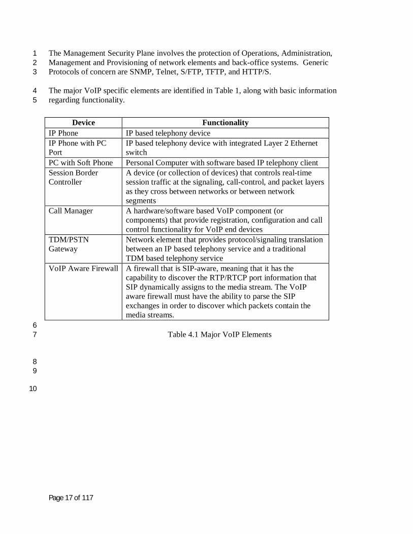
The Management Security Plane involves the protection of Operations, Administration, 1 Management and Provisioning of network elements and back-office systems. Generic 2 Protocols of concern are SNMP, Telnet, S/FTP, TFTP, and HTTP/S. 3
The major VoIP specific elements are identified in Table 1, along with basic information 4 regarding functionality. 5
Device Functionality IP Phone IP based telephony device IP Phone with PC Port
IP based telephony device with integrated Layer 2 Ethernet switch
PC with Soft Phone Personal Computer with software based IP telephony client Session Border Controller
A device (or collection of devices) that controls real-time session traffic at the signaling, call-control, and packet layers as they cross between networks or between network segments
Call Manager A hardware/software based VoIP component (or components) that provide registration, configuration and call control functionality for VoIP end devices
TDM/PSTN Gateway
Network element that provides protocol/signaling translation between an IP based telephony service and a traditional TDM based telephony service
VoIP Aware Firewall A firewall that is SIP-aware, meaning that it has the capability to discover the RTP/RTCP port information that SIP dynamically assigns to the media stream. The VoIP aware firewall must have the ability to parse the SIP exchanges in order to discover which packets contain the media streams.
6 Table 4.1 Major VoIP Elements 7
8 9
10
Page 18 of 117
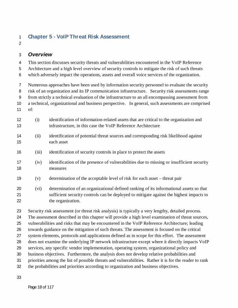
Chapter 5 - VoIP Threat Risk Assessment 1 2
Overview 3
This section discusses security threats and vulnerabilities encountered in the VoIP Reference 4 Architecture and a high level overview of security controls to mitigate the risk of such threats 5 which adversely impact the operations, assets and overall voice services of the organization. 6
Numerous approaches have been used by information security personnel to evaluate the security 7 risk of an organization and its IP communication infrastructure. Security risk assessments range 8 from strictly a technical evaluation of the infrastructure to an all encompassing assessment from 9 a technical, organizational and business perspective. In general, such assessments are comprised 10 of: 11
(i) identification of information-related assets that are critical to the organization and 12 infrastructure, in this case the VoIP Reference Architecture 13
(ii) identification of potential threat sources and corresponding risk likelihood against 14 each asset 15
(iii) identification of security controls in place to protect the assets 16
(iv) identification of the presence of vulnerabilities due to missing or insufficient security 17 measures 18
(v) determination of the acceptable level of risk for each asset – threat pair 19
(vi) determination of an organizational defined ranking of its informational assets so that 20 sufficient security controls can be deployed to mitigate against the highest impacts to 21 the organization. 22
Security risk assessment (or threat risk analysis) is typically a very lengthy, detailed process. 23 The assessment described in this chapter will provide a high level examination of threat sources, 24 vulnerabilities and risks that may be encountered in the VoIP Reference Architecture; leading 25 towards guidance on the mitigation of such threats. The assessment is focused on the critical 26 system elements, protocols and applications defined as in scope for this effort. The assessment 27 does not examine the underlying IP network infrastructure except where it directly impacts VoIP 28 services, any specific vendor implementation, operating system, organizational policy and 29 business objectives. Furthermore, the analysis does not develop relative probabilities and 30 priorities among the list of possible threats and vulnerabilities. Rather it is for the reader to rank 31 the probabilities and priorities according to organization and business objectives. 32
33

Page 19 of 117
Asset Classification 1
A key aspect to the security risk assessment is the identification of assets which define the VoIP 2 Reference Architecture, and in particular selection of those assets which are considered most 3 critical to be protected from compromise, exploitation, interruption or loss. Assets may be 4 physical systems, information, service level agreements, regulatory commitments, staff and any 5 other physical or logical element that is important for the organization to protect. 6
The number of critical assets for an organization may easily exceed one hundred. To make the 7 analysis more manageable, only the most common assets will be reviewed in this document. 8 High level asset groups or asset containers have been defined to categorize the various assets 9 which comprise the basic VoIP architecture. These high-level asset groups are: 10
Hardware systems which include the IP PBX, Call Controller or call manager, media 11 gateway, IP phone handset, desktops, databases, and supplemental servers. 12
Software such as operating systems, VoIP related application software (i.e. soft phone) 13 and third-party security software such as malicious code detection/removal, anti-virus, 14 host based firewall applications. 15
Network infrastructure comprised of routers, switches, firewalls, VPN devices, 16 Intrusion detection / prevention systems. 17
Staff personnel responsible for the architecture, network and security operations, system 18 administration and software development; including the enforcement of policies and 19 processes critical to the security of the organization. 20
21 As noted earlier in the document the only most basic elements of a VoIP service infrastructure is 22 defined in our VoIP Reference Architecture. Platforms such as voicemail, audio conferencing 23 server (or media servers), application servers, fax over IP, email integration for unified 24 messaging, session border controllers, SIP trunks, and other elements present in a comprehensive 25 unified communication solution will be assessed in the future. 26 27 It is important to understand the security requirements of each critical asset so one may 28 understand how a particular threat will adversely impact the VoIP Reference Architecture. The 29 core principles of information security – confidentiality, integrity and availability, are asked 30 upon each critical asset to identify the importance of the requirements on the asset (i.e., low, 31 moderate and critical). This evaluation of each asset will help to identify the security controls to 32 best protect the particular asset described later in the section. The core principles (or 33 requirements) of information security are defined as follows: 34
Confidentiality. The “property of preventing disclosure of information to unauthorized 35 individuals, processed or systems.” Typically some form of encryption is used to satisfy 36 this security requirement. 37
Integrity. The accuracy of information created, modified, stored and delivered within 38 and possibly outside of the organization with proper authentication and authorization to 39 do so. 40

Page 20 of 117
Availability. The property of ensuring the network, information, service or application is 1 accessible when needed by an authorized entity. 2
3 Other well-known security requirements such as authentication, authorization, accountability and 4 non-repudiation are not ranked for its importance on each critical asset in this version of the 5 white paper. The following classifications of security importance are used for this assessment: 6
Security Importance
Definition
Low The compromise or loss of the security principle from the asset will result in no loss of confidence or risk seen by the organization.
Moderate The compromise or loss of the security principle from the asset will cause loss of confidence and risk to the VoIP service infrastructure with service degradation experienced by many individuals however no loss of availability or critical data.
Critical The compromise or loss of the security principle from the asset will cause loss of availability and/or complete compromise resulting in the VoIP service not being useable.
Table 5.0 – Security Importance Definition 7
Table 5.1 below identifies system assets and corresponding informational assets which are 8 considered critical to the VoIP Reference Architecture, including the degree of importance each 9 core security requirement or principle has on each asset. 10 11
System
Asset
Informational
Asset
Importance Of Security Requirement
Confidentiality Integrity Availability
IP Phone Handset
Operating System Low Moderate Moderate
Configuration Low - Moderate Moderate Moderate
Media Moderate Moderate Critical
Signalling Moderate Critical Critical
Management Critical Critical Critical
12

Page 21 of 117
1
System
Asset
Informational
Asset
Importance Of Security Requirement
Confidentiality Integrity Availability
Desktop Operating System Low Moderate Moderate
VoIP Application (i.e., Soft phone)
Low Moderate Moderate
Media Moderate Moderate Critical
Signalling Moderate Critical Critical
Management Critical Critical Critical
System
Asset
Informational
Asset
Importance Of Security Requirement
Confidentiality Integrity Availability
IP PBX (includes media gateway, Call Controller / call manager) [Note 1]
Operating System Low Critical Critical
Configuration Moderate Critical Critical
Dial Plan Moderate Critical Critical
Call Detail Records (and Billing Info)
Critical Critical Critical
Software Licenses Low Moderate Critical
Media Moderate Moderate Critical
Signalling Moderate Critical Critical
Management Critical Critical Critical
System
Asset
Informational
Asset
Importance Of Security Requirement
Confidentiality Integrity Availability
Element Manager
Operating System Low Critical Moderate
Configuration and Management
Moderate Critical Moderate
2

Page 22 of 117
1
System
Asset
Informational
Asset
Importance Of Security Requirement
Confidentiality Integrity Availability
Network (i.e., router, switch, firewall, VPN, IPS)
OS / Firmware Low Critical Critical
Media Moderate Moderate Critical
Signalling Moderate Critical Critical
Management Critical Critical Critical
System
Asset
Informational
Asset
Importance Of Security Requirement
Confidentiality Integrity Availability
DNS, DHCP, TFTP, RADIUS
Operating System Low Critical Critical
User Identification Low Critical Critical
User Profiles Moderate Critical Critical
Configurations (phones)
Low - Moderate Critical Critical
Table 5.1 Critical System and Informational Assets 2
[Note 1] The call processing and media gateway functionality may be composed of a distributed or centralized 3 (appliance) architecture dependent on the specific vendor. 4
Threats on Critical Assets 5
Once critical assets are identified, the next step in a security risk assessment is to identify 6 potential threats and likelihood for the threat to occur in the organization. The security risk 7 assessment reviewed possible threats to the critical assets of our VoIP Reference Architecture by 8 identifying potential threat sources. A security threat is an entity with the capability, intent and 9 method to compromise, damage or alter an information system or information by taking 10 advantage of a weakness or vulnerability inherent to the exploited system or information. The 11 organization must understand how to profile a threat on its network infrastructure, devices and 12 data; and only afterwards can the organization properly develop a security strategy to protect 13 against potential threats. 14
15

Page 23 of 117
A threat profile is defined by a specific entity or situation as the source of the security risk, 1 method of access into the organization, the entity’s authorized role in the organization, and 2 action taken by the entity to exploit a vulnerability to the asset in the organization. Many threats 3 will be initiated in a malicious and illegal manner however accidental threats will occur and must 4 be considered in the assessment and overall security mitigation strategy. Examples of deliberate 5 threat sources include malicious users residing inside and outside the VoIP service infrastructure, 6 downloadable software with malicious code, and physical disruptions. Accidental threat sources 7 may include power outage, fire, flood, software, hardware and firmware failures, and mis-8 configurations of phones and servers; although these too may be deliberate. Furthermore, such 9 threat sources may access an organization’s network infrastructure via numerous methods from 10 communication channels such as the Internet, LAN, WAN, wireless and modem, to physical 11 access methods such as laptops, USB memory sticks and drives, and third-party software. 12 13 It is threat sources with the possibility to exploit the vulnerabilities of each asset which leads to 14 consequences adversely impacting the organization and business objectives that must be 15 examined in the assessment. The following identifies common threat sources which may 16 compromise and exploit one or more critical assets to an organization. Some of these threat 17 sources are accidental whereas other threat sources are deliberate or intentional. Here are the 18 potential threat sources: 19
Malicious users such as disgruntled employees, contractors, hackers which may establish 20 an attack vector from either inside or outside the organization. 21
Accidental users such as trusted employees and contractors whose actions or inactions 22 may have caused an exploitable vulnerability. 23
Configuration weaknesses and mistakes from trusted actors. 24 Social engineering where confidential/sensitive information on the organization, 25
infrastructure and services is discovered using deception or misrepresentation. 26 Email with embedded Web links and malicious attachments. 27 Software such as flaws in the implementation of an application, protocol or operating 28
system, or delivery of malicious code (i.e., malware, virus, trojan, worm) into the 29 organization. 30
Hardware such as a defect in the hardware or delivery of confidential / sensitive 31 information to unauthorized personnel (i.e., USB memory sticks, used laptops and hard 32 drives). 33
Data leakage where confidential/sensitive information on a laptop and removable media 34 with the possibility of being stolen and/or discovered by malicious actors. 35
Third party providers providing an access conduit into the organization for deliberate 36 and accidental threats. 37
Physical interruption due to accidental or deliberate causes (i.e., power outage, flood, 38 severed Internet or PSTN circuit/cable, system upgrades, etc) 39
Unknown threats – thus risk assessment is an ongoing process. 40 41

Page 24 of 117
Every organization has limited resource capabilities (i.e., personnel, budget) to implement the 1 ideal security strategy to address all potential threats. It is important to determine the potential 2 risk (or product of likelihood and impact) for a threat to actually exploit a vulnerability and cause 3 damage to the organization. The damage or impact may be qualified as a loss of availability, 4 integrity and confidentiality; including other possible losses. It is not possible to identify all 5 risks, nor is it possible to eliminate all risks. Therefore the organization must develop criteria to 6 prioritize such risks, and apply more resources to protect higher risk assets above lower risk 7 assets. Calculation of the threat likelihood may range from a simple qualitative classification to 8 a more in depth quantitative approach using historical data and trend analysis. Selection of the 9 most appropriate measurement for threat likelihood is out-of-scope for this white paper. The 10 white paper will utilize a coarse qualitative classification to illustrate the assessment performed 11 on our VoIP Reference Architecture. The classification is based on two key factors – time frame 12 of threat occurrence and location of threat source. Other factors such as access method, 13 accidental versus deliberate intention, and other dependencies can provide further granularity to 14 determine the threat likelihood, however, these factors were not used for this assessment. The 15 following scoring (or ranking) criteria should be used to determine the likelihood of a threat on 16 the VoIP Reference Architecture; the criteria is based on the ETSI TIPHON Threat Likelihood 17 Scoring Criteria [2]. 18
Low means (i) threat needs to bypass strong technical controls to exploit an organization, 19 or (ii) motivation for the threat is very low. 20
Medium means (i) threat needs to bypass less than strong technical controls without 21 significant effort, or (ii) motivation for the threat is reasonable. 22
High means (i) there are not sufficient controls to mitigate or prevent the threat, or (ii) 23 motivation for the threat is high. 24
25 Basic threat sources such malicious users, configuration weaknesses, hardware and software 26 flaws, and physical disruptions were considered in the assessment of our VoIP Reference 27 Architecture and are depicted in Table 5.2 below. Other threat sources were not considered for 28 this whitepaper. 29
With the convergence of voice and data across a common IP network, it is anticipated the 30 likelihood for a threat source to adversely impact the organization is higher from the IP / data 31 network than PSTN (i.e., POTS). Thus the primary focus of this risk assessment will be with 32 LAN/WAN/Internet residing actors attempting to use these threats sources against the 33 organization. However threats from PSTN initiated weaknesses such as modems to gain 34 unauthorized access to systems are common enough that appropriate security controls will be 35 identified later in the document. Furthermore, as IP connectivity to the Public VoIP Network 36 (i.e., SIP trunks) becomes readily available, threats from the Public VoIP Network may certainly 37 increase. For purposes of simplicity, wireless IP access and remote VPN access (i.e., SSH, 38 IPSec) are considered an external method of access with threats similar to attacks from the 39 Internet. 40

Page 25 of 117
1
Threat
Sources
Threat Likelihood Based on Access Vector
Internal Network External / Internet External / PSTN
Malicious or Accidental Users
High High Medium
Configuration weaknesses
High High Medium
Hardware flaws High Medium Low
Software flaws High High Low
Physical Interruptions
High Medium Low
Table 5.2 Threat Sources and Likelihood 2
3
Threat likelihood and threat impact are not the same. It is possible that a high probability threat 4 (i.e., hardware failure) may have a very low impact to the organization which implements system 5 redundancy. In other circumstances a threat with a smaller likelihood to occur, such as the loss 6 of a PSTN circuit, will have a critical impact to the organization. 7
8
The next step to the security risk assessment is to identify for each critical asset those threats 9 which potentially have a high likelihood and high adverse impact to the organization. The 10 following threat impact criteria have been identified; based on the ETSI TIPHON Threat Impact 11 Scoring Criteria [2]. 12
: 13
Minor (or Low) – impact will result in no loss of confidence seen by the organization. A 14 few individuals may be temporarily impacted. Potential damage will remain low. 15
Major (or Medium) – impact will cause loss of confidence to the VoIP service 16 infrastructure with service degradation experienced by many individuals however no loss 17 of availability or critical data. Potential damage can not be neglected. 18
Critical (or High) – impact will cause loss of availability and/or complete compromise 19 resulting in the VoIP service not useable. Potential damage may be severe. 20
21

Page 26 of 117
Risk is a product of potential impact of threat on organization and likelihood for threat to occur. 1 Table 5.3 illustrates the threat risk scoring criteria used by ETSI TIPHON [2]. Low is scored 1, 2 Medium scored 2 and High scored 3; and thus a risk from 1 (lowest) to 9 (highest). 3 Countermeasures should always be implemented for higher risk threats before lower risks. 4
5
Threat
Impact
Threat Likelihood
Low Medium High
Low Minor Risk Minor Risk Major Risk
Medium Minor Risk Major Risk Critical Risk
High Major Risk Critical Risk Critical Risk
Table 5.3 ETSI TIPHON Threat Risk Score 6
7
Next is to apply the threat impact, likelihood and risk scoring methodology defined above to the 8 critical assets identified for the VoIP Reference Architecture in Table 5.1. As described earlier 9 certain threat sources are more likely to occur inside the organization as oppose to outside. 10 Table 5.4 illustrates the risk to the assets from threats originating from inside the organization; 11 however risk of exploitation is based on organization’s deployment of security controls. The 12 same methodology may be applied to threats originating from outside. 13
14
System
Asset
Informational
Asset
Threat
Impact
Threat
Likelihood
Risk
IP Phone Handset
Operating System Low Medium Minor
Configuration Low High Major
Media Low Low Minor
Signalling Low Low Minor
Management Low Medium Minor
Desktop Operating System Low High Major

Page 27 of 117
VoIP Application (i.e., Soft phone)
Low High Major
Media Low Low Minor
Signalling Low Low Minor
Management Low Medium Minor
Call Controller and Media Gateway (or IP PBX)
Note 1
Operating System High High Critical
Configuration High High Critical
Dial Plan High High Critical
Call Detail Records (and Billing Info)
Medium High Critical
Software Licenses Medium High Critical
Media Medium Low Minor
Signalling Medium Low Minor
Management Medium Medium Major
Element Manager
Operating System Low High Major
Configuration and Management
Low High Major
Network (i.e., router, switch, firewall, VPN, IPS)
OS / Firmware High Medium Critical
Media Medium Medium Major
Signalling Medium Medium Major
Management Medium Medium Major

Page 28 of 117
DNS, DHCP, TFTP, RADIUS
Operating System High High Critical
User Identification Medium High Critical
User Profiles Medium High Critical
Configurations (phones)
Medium High Critical
1
Table 5.4 Threat Risk Score of Critical Assets From Internal Threats 2
3
Vulnerabilities Exploited By Threats 4
With threats identified for each critical asset, the next step is to identify what possible 5 vulnerabilities may exist for each asset. As performed with threat sources, the exhaustive list of 6 vulnerabilities will need to be prioritized (or ranked) based on the likelihood or risk for the 7 vulnerability to be exploited by a threat and its adverse impact or consequence on the 8 organization. Such consequences include disclosure or viewing of sensitive information, 9 modification of important or sensitive information, loss of important information, and 10 interruption of access to information, applications and services. This section will discuss 11 vulnerabilities which may exist in the VoIP Reference Architecture and its impact to the 12 organization should appropriate security controls not be implement to protect the applicable 13 assets. 14
15
Vulnerability is a weakness or flaw in the design and implementation of the VoIP protocols and 16 applications, operating system, supplemental services (i.e., DNS, DHCP), network, physical 17 infrastructure, policies and procedures which may be exploited. Not only is the risk of a 18 vulnerability specific to the asset and information associated with the asset, the network location 19 of where the vulnerability is exploited is also of importance. Typically, an organization’s 20 network is partitioned into various security zones (i.e. trusted, DMZ and untrusted), each with its 21 unique security requirements. It is part of the security risk assessment to determine what risk the 22 vulnerability has on a specific asset in a particular security zone within the network. 23
24
As a threat gains access into the organization’s network, the threat attempts to discover assets 25 with exploitable vulnerabilities. Fundamentally, this is performed by scanning for specific 26 services and known ports (aka, footprinting), identify the device based on the running services, 27

Page 29 of 117
ports and vendor ID in MAC address, and afterwards attempt to compromise the device based on 1 vulnerabilities known to exist for the device. 2
3
A threat may attempt to exploit numerous logical elements (i.e., module, process) of an asset or 4 focus on a single specific element. From an operational perspective, each element can be viewed 5 in terms of how the asset is involved with the VoIP service. The asset may be involved with the 6 signaling, media or management aspect of the VoIP service. Each type of traffic or ‘plane’ has 7 its own protocols. 8
Media or Bearer Plane is responsible to deliver the voice packets between IP endpoints 9 such as IP phones and media gateways. RealTime Protocol (RTP) and RealTime Control 10 Protocol (RTCP) are the key protocols used for media. 11
Signalling or Control Plane is responsible to deliver the call setup, teardown and mid-12 call information between IP endpoints, Call Controllers/call managers, and supplemental 13 servers such as DNS, DHCP, TFTP. The signalling plane is used to initiate traffic across 14 the media plane. For this assessment Session Initiation Protocol (SIP) is the primary 15 VoIP signalling protocol. 16
Management Plane is responsible to deliver the administration, management and 17 monitoring traffic out-of-band with respect to the actual voice call. The management 18 plane may use the same network as the signalling and media planes, or a separate 19 network may be provided for management purposes only. Various remote terminal (i.e., 20 Telnet, SSH), Web/GUI console (i.e., HTTP/HTTPS), file transfer (i.e., FTP, TFTP, 21 SFTP, SCP), configuration and monitoring (i.e., SNMP) and management user 22 authentication (i.e., RADIUS, TACACS) protocols are used across the management 23 plane. 24
25
The following are common types of vulnerabilities possible in the VoIP Reference Architecture. 26
Configuration weakness of the operating system and VoIP applications results in the use of 27 unnecessary services and open TCP/UDP ports, insecure management and file transfer protocols, 28 default service settings (i.e., use of ‘public’ community string for SNMP), and other vendor 29 assigned default settings simply enabled for ease of deployment. A weak configuration may 30 allow the attacker to exploit other vulnerabilities such as unauthorized access, reconnaissance 31 and denial-of-service. 32 33 Unauthorized access due to weak authentication typically results from use of credentials such as 34 a source IP address, default vendor passwords, simple passwords, and unencrypted (or cleartext) 35 passwords as the sole mechanism for validating identities and providing authorization for a user 36 or device to access resources. Failure to properly authenticate users can allow the realization of 37 additional threats including tampering, fraudulent use of the asset, eavesdropping, denial of 38 service, or compromise of system integrity. 39
40

Page 30 of 117
Malicious Code is defined in NIST IR 7298 as “Software or firmware intended to perform an 1 unauthorized process that will have adverse impact on the confidentiality, integrity, or 2 availability of an information system. A virus, worm, Trojan horse, or other code-based entity 3 that infects a host.” Malicious code can be used to gather information on system management 4 and/or signalling and control for fraudulent use, denial of service, or further compromise of the 5 system. 6 7 Reconnaissance and Enumeration occur when a potential attacker seeks information about an 8 asset or system to cause an exploit or compromise. IP and MAC addresses, operating system and 9 application versions, open ports, and services used by the assets are some types of information 10 which can be harvested. Information may be gathered using any number of common protocols 11 and services such as BOOTP, TFTP, SNMP, HTTP, and SIP, including social engineering 12 techniques. As the attacker understands the organization’s VoIP deployment, the attacker can 13 probe or enumerate the organization for specific VoIP vulnerabilities. 14 15 Spoofing (or masquerading) involves presenting falsified identity information to gain 16 unauthorized access to a system; including a means to bypass access control measures. The 17 falsified identity may be a MAC or IP address, SIP Uniform Resource Identifier (URI), caller ID, 18 or other form of identity. FIPS 191 notes spoofing involves: (i) the ability to receive a message 19 by masquerading as the legitimate receiving destination, or (ii) masquerading as the sending 20 machine and sending a message to a destination. Attackers can use spoofing to launch further 21 attacks such as unauthorized access, fraudulent calls, denial-of-service, and man-in-the-middle 22 attacks. 23 24 Impersonation involves the pretence of legitimacy using falsified or captured credentials, such 25 as a rogue call server pretending to be the authorized call server. Impersonation relies heavily on 26 spoofing and eavesdropping to acquire the information needed. Impersonation can facilitate 27 registration and media session hijacking, toll fraud, denial of service, and system compromise. 28 29 Eavesdropping occur when an attacker can capture media, signalling or management traffic 30 without authorization. An attacker may use network assets to ‘sniff’ and forward duplicated 31 packets or redirect the signalling and media packets to a rogue device so the attacker may capture 32 the targeted traffic. Eavesdropping affects the confidentiality of a voice conversation delivered 33 across the media plane. When applied against the Signalling and Management planes, 34 eavesdropping can provide the attacker with sensitive information such as credentials (i.e., user 35 ID, password, PIN, telephone number) for use in more complex system intrusions such as 36 unauthorized access, toll fraud and man-in-the-middle attacks. 37 38 Signalling and Media Manipulation can lead to threats to communication integrity. Media 39 manipulation can include deletion, insertion, redirection and replay of media. Signalling 40 manipulation can result in denial of service via the generation of false registration packets which 41 tie up phone operations, the generation of invite packets which cause the phone to ring, and 42 sending “bye” packets which disconnect calls. It can also result in unauthorized redirection of 43 calls and facilitate the implementation of a rogue proxy onto the network. 44 45

Page 31 of 117
Fuzzing occurs when an attacker sends messages with malformed syntax, incorrect or 1 unexpected message sequence to a system with the intent to crash it. This vulnerability may lead 2 to a type of DoS attack causing buffer overflows without the need for excessive flooding of 3 packets. Fuzzing may impact the availability and possibly the integrity or accountability of 4 organization’s VoIP service. 5 6 Man-in-the-middle attacks use interception, impersonation and spoofing to insert a rogue device 7 into the communications path as a legitimate server or endpoint. The impacts include 8 eavesdropping on a conversation, the deletion, injection or replay of media or signalling content, 9 reconstruction of DTMF tones, and redirection of a conversation. Interception of the traffic may 10 be performed at the network level (i.e., ARP poisoning) or application level (i.e., SIP registration 11 hijacking). 12 13 Denial-of-Service (DoS) attacks result in the disruption to the network, system or service 14 through the use of packets designed to overwhelm it. Packets may be carefully crafted payloads 15 to exploit an operating system or application, or a flood of packets to overburden the target. 16 Impacts range from ability to block legitimate calls, degradation of call quality, to crashing 17 segments of the network, system or application. Types of packet flooding range from ICMP, 18 UDP and TCP packets to application flooding such as various SIP protocol messages (i.e., Invite, 19 Register, Notify, Info, Option, Bye). Some flooding attacks may be unintentional such as SIP 20 endpoints configured with very short registration intervals, problematic software, and high traffic 21 circumstances (i.e., simultaneous reboot). Regardless, DoS attacks against VoIP/IP PBX 22 systems, DHCP, TFTP, DNS, and network-security devices can adversely impact the overall 23 VoIP service. 24 25 Theft of Service/Toll Fraud involves the unauthorized use of assets to place a call without 26 approval or payment. Typically a malicious actor gains access to a VoIP asset due to weak 27 authentication, spoofing, eavesdropping and impersonation. 28 29 VOIP Spam (or Spam over Internet Telephony – SPIT) and Phishing involve the unsolicited 30 use of email messages, voice messages or phone calls to gain credentials or other sensitive data 31 through social engineering. At some point, the volume of VOIP Spam can also degrade system 32 performance. 33 34
35

Page 32 of 117
Table 5.5 identifies how each vulnerability classification will typically impact the organization 1 with respect to its signalling, media and management traffic. 2
3
Vulnerability Impact To Traffic Plane
Media Signalling / Control
Management
Unauthorized Access - Weak Authentication
Compromise, Loss of confidentiality
Compromise, Loss of integrity
Compromise, Loss of integrity
Configuration Weakness
Degrade Call Quality, Disclosure
Compromise,
Disclosure
Compromise,
Disclosure
Malicious Code Degrade System Performance
Compromise, Degrade System
Performance
Compromise, Degrade System
Performance
Reconnaissance, Enumeration
Host Discovery - Disclosure
Host Discovery - Disclosure
Host Discovery – Disclosure
Spoofing (masquerading)
Confidentiality Loss of availability, Integrity
Integrity
Eavesdropping Confidentiality Integrity Integrity
Signalling And Media Manipulation / Hijacking
Integrity Integrity, Disruption, Degrade
Performance
N/A
Fuzzing Degrade System Performance
Loss of availability, Degrade
Performance
Degrade System Performance
Impersonation Confidentiality Integrity Integrity
4

Page 33 of 117
1
Vulnerability Impact To Traffic Plane
Media Signalling / Control
Management
Man-In-The-Middle Attacks
Intercept and manipulate to
impact confidentiality
Intercept and manipulate to
impact integrity
Intercept and manipulate to
impact integrity
Denial-Of-Service Attacks
Degrade Call Quality & System
Performance
Loss of Availability, Resource exhaustion
Loss of Reliable In- band Management
Theft of Service / Toll Fraud
Unauthorized or fraudulent calls
N/A N/A
VoIP Spam And Phishing
Degrade System Performance
Identity Theft, Disclosure
Disclosure
Table 5.5 Vulnerability Impact on Traffic Plane 2
3
A threat which has successfully exploited a vulnerability of a critical asset will have adversely 4 impacted the VoIP Reference Architecture. This impact or consequence will broadly result in 5 the unauthorized disclosure of information, the modification of information or operation for 6 unauthorized purposes, interruption of an asset, service or network without cause, or loss of an 7 asset, service or network. The following vulnerability impact classifications on assets have been 8 identified: 9
Low – impact will result in no loss of confidence or degradation of service seen by the 10 organization. A few individuals may be temporarily impacted. 11
Medium – impact will cause loss of confidence to the VoIP service infrastructure with 12 service degradation experienced by many individuals however no loss of availability or 13 critical data. 14
High – impact will cause loss of availability and/or complete compromise resulting in the 15 VoIP service not useable. 16
17
18

Page 34 of 117
Table 5.6 shows the potential impacts of select vulnerabilities in four consequential areas: 1 disclosure, modification, interruption, and loss. These are average impacts and not necessarily 2 the worst case impact. 3
Vulnerability Impact of Vulnerability on Asset (= Consequence)
Disclosure Modification Interruption Loss
Unauthorized Access - Weak Authentication
High High High High
Configuration Weaknesses
Low-Medium High Medium Medium
Malicious Code Low High Medium Low
Reconnaissance Low Low Low Low
Spoofing Low Medium Low Low
Eavesdropping Low Low Low Low
Signalling And Media Manipulation / Hijacking
Low High Medium Medium
Fuzzing Low Medium Medium Low
Impersonation Medium High Low Low
Man-In-The-Middle Attacks
Low High Medium Medium
Denial-Of-Service Attacks
Low Low High Medium - High
Theft of Service / Toll Fraud
Low Low Low High
VoIP Spam And Phishing
Medium Low Low Low
Table 5.6 Vulnerability Impact on Asset 4

Page 35 of 117
Table 5.7 shows the most critical security requirements, most critical impacts, and most likely 1 threat vulnerabilities for selected system assets. 2
System
Asset
Informational Asset
Most Critical Security Req
Most Critical Impact
Most Likely Threat-Vulnerabilities
IP Phone Handset
Operating System Integrity Modification Traditional Data Exploits
Configuration Integrity Loss of Avail. Weak Authentication
Media Integrity Call Quality Degradation / Loss of Avail.
DoS Attack
Signalling Integrity Interception Eavesdropping
Management Integrity Interception Eavesdropping
System
Asset
Informational Asset
Most Critical Security Req
Most Critical Impact
Most Likely Threat-Vulnerabilities
Desktop Operating System Integrity Loss of Avail. Malicious Code, Traditionnel Data
Exploits
VoIP Application (i.e., Soft phone)
Integrity Loss of Avail. Configuration Weakness
Media Integrity Call Quality Degradation / Loss of Avail.
DoS Attack
Signalling Integrity Interception Eavesdropping
Management Integrity Interception Eavesdropping
3

Page 36 of 117
1
System
Asset
Informational Asset
Most Critical Security Req
Most Critical Impact
Most Likely Threat-Vulnerabilities
Call Controller and Media Gateway (or IP PBX)
Operating System Integrity Modification Malicious Code, Traditionnel Data
Exploits
Configuration Integrity Loss of Avail. Configuration Weakness
Dial Plan Integrity Loss of Avail Theft of Service / Toll Fraud
Call Detail Records (and Billing Info)
Integrity and Confidentiality
Loss of Avail.,
Repudiation
Weak Authentication, Configuration
Weakness
Software Licenses and Operational Service
Availability Loss of Avail. Weak Authentication
Media Integrity Call Quality Degradation / Loss of Avail.
DoS Attack
Signalling Integrity Interception Eavesdropping
Management Integrity Interception Eavesdropping
System
Asset
Informational Asset
Most Critical Security Req
Most Critical Impact
Most Likely Threat-Vulnerabilities
Element Manager
Operating System Integrity Modification Malicious Code, Traditionnel Data
Exploits
Configuration and Management
Availability Unauthorized Access
Weak Authentication
2

Page 37 of 117
1
System
Asset
Informational Asset
Most Critical Security Req
Most Critical Impact
Most Likely Threat-Vulnerabilities
Network (i.e., router, switch, firewall, VPN, IPS)
Operating System Integrity Modification Traditional Data Exploits
Media Integrity Call Quality Degradation / Loss of Avail.
DoS Attack
Signalling Integrity Interception Eavesdropping
Management Integrity Interception Eavesdropping
System
Asset
Informational Asset
Most Critical Security Req
Most Critical Impact
Most Likely Threat-Vulnerabilities
DNS, DHCP, TFTP, RADIUS
Operating System Integrity Modification Malicious Code, Traditionnel Data
Exploits
User Identification (i.e., IP Address)
Integrity Compromise, Loss of Avail
Configuration Weakness, Malicious
Code, DoS
User Profiles Integrity Compromise Weak Authentication, Configuration
Weakness
Configurations (i.e., Phones)
Integrity Compromise Weak Authentication,
Configuration Weakness
Table 5.7 Most Critical Impact and Mostly Likely Threat Vulnerabilities 2
3
Page 38 of 117
Security Controls To Mitigate Threats and Vulnerabilities 1
Organizations can perform frequent security risk assessments and implement a defense-in-depth 2 security strategy of security controls and countermeasures to prevent, protect and mitigate 3 against threats and vulnerabilities. However the risk remains for a malicious actor to gain access 4 to the network and successfully initiate an attack against the VoIP service infrastructure. As a 5 result, security must be viewed as an ongoing process of security audits, identification of new 6 threats and vulnerabilities, testing, hardware and software upgrades, and implementation of new 7 security mitigation controls. 8 9 This section provides a high level overview of typical security controls and countermeasures to 10 protect the VoIP Reference Architecture from threats and vulnerabilities identified earlier in the 11 document. 12 13 The following highlights common classifications of security controls applicable to VoIP: 14
Hardening of Operating System / Firmware – securing the operating system / firmware 15 including configuration files for all elements of a VoIP service infrastructure. Disable all 16 unnecessary services and ports which are not required for the device. Required services to be 17 bound to specific interface, and not unnecessary interfaces. Logging should be enabled. It is 18 recommended to use secure protocols which encrypt the payload. Host based intrusion 19 detection, anti-virus, malware protection are recommended. Other mitigation techniques include 20 up-to-date patches installed on the device. 21 22
Strong Authentication – the process to identify an individual, message, device or information 23 as authentic and not altered or forged. Simple authentication may be performed using a 24 username and password however this common method provides a weak form of identity. Basic 25 and message digest authentication using MD5 checksum defined for HTTP and SIP are also 26 considered weak methods of authentication. Digital certificates, as defined in ITU X.509 27 standard, may be used to establish the validity of a message or device. Public Key Infrastructure 28 (PKI) is a well known trusted method to create, manage, store, distribute and revoke certificates. 29 Unilateral authentication occurs when the server is authenticated but not the client, whereas 30 bilateral (or mutual) authentication occurs when both parties of the session (or conversation) are 31 authenticated. Transport Layer Security (TLS) using digital certificates is considered as a strong 32 authentication mechanism for signalling and management. And Secure RTP (SRTP) using digital 33 certifications is considered a strong authentication mechanism for delivery of media. Other forms 34 of authentication such as Secure Shell version 2 (SSHv2) and one-time password tokens are also 35 used for authentication of management sessions. 36 37
38

Page 39 of 117
Access Control in the context of this document refers to a software element which provides a 1 controlled access to resources. Physical devices such as firewalls, intrusion prevention system 2 or routers employed with Access Control Lists (ACLs) are typically used to restrict access based 3 on IP addresses and TCP/UDP ports. Capabilities such as packet filtering, deep packet 4 inspection, white- and black listing are commonly used by these devices. Call Admission 5 Control (CAC) is used to control the number of concurrent calls that may be delivered across the 6 network; typically supported on the Call Controller (or IP PBX). 7 8 Authorization – the process to specify access rights to an individual, message, device or 9 information using a defined Role Based Access Control (RBAC) model and adhere to Least 10 Access Principle where access to services, devices and networks is restricted unless otherwise 11 permitted. 12 13 Encryption – the process to transform clear or plaintext information into an unreadable format 14 for all users and devices except those possessing the proper credentials. Encryption can protect 15 the confidentiality of the information however additional techniques are required to protect the 16 integrity of the information. It is recommended encryption be performed at the endpoints (i.e., 17 IP phone, media gateway) and not in the network using IPSec tunnels in order to ensure end-to-18 end integrity and confidentiality. Secure RTP (SRTP) encrypts the RTP and RTCP protocols 19 used to encapsulate media, protecting the media from disclosure, modification and replay. SIP 20 over TLS is used to encrypt the SIP signalling protocol. And the SSL protocol is used to encrypt 21 management protocols such as SSH, SFP, SCP and HTTPS. Encryption of files should be 22 performed to ensure integrity (i.e., configuration, firmware) and privacy of confidential or 23 sensitive data (i.e., call detail records). 168-bit Triple Data Encryption Standard (3DES) or 128-24 bit Advanced Encryption Standard (AES) typically used for encryption. 25 26 Voice and Data Segregation Using VLANs – Virtual LANs are used to segment the network 27 broadcast domains logically across a switched network. Separate VLANs should be used for 28 voice and data traffic to minimize the impact of data leakage on voice traffic. VLANs provide 29 some basic protection against ARP based eavesdropping, denial-of-service, reconnaissance and 30 toll fraud attacks. Use of soft phones violates this security control and thus increases risk of a 31 data originating vulnerability to impact VoIP. 32 33 Topology Hiding – assignment of private IP address space (RFC 1918) for the critical VoIP 34 systems to ensure direct access from the Internet is not possible. Typically these privately 35 addressed VoIP systems would be behind a firewall. Network Address Translation (NAT) 36 including NAT Traversal for VoIP is out-of-scope with respect to this document. 37 38 Denial of Service Protection – mechanism to block or rate limit packets based on protocol type, 39 IP address, UDP/TCP port or specific application payload content. From a server perspective, the 40 resource processing overhead may be reduced by configuring the SIP server not to process and 41 respond to illegitimate requests with an error code. 42 43
44

Page 40 of 117
Call Pattern Analysis – use of VoIP aware firewall and intrusion detection / prevention 1 software and systems to check for malformed packets with respect to the syntax and semantics, 2 and abnormal traffic patterns which may be considered as a malicious threat. This security 3 control protects against fuzzing and toll fraud. 4 5 Monitoring, Logging and Reporting – Monitoring involves real time oversight and analysis of 6 events on systems and networks. Logging is the capture of event data for further review to 7 ensure quality and for the facilitation of incident response. Reporting captures event information 8 and formulates it to assist in compliance, benchmarking, and trend analysis. 9 10 Auditing – the use of audit trails to record access, modification, and deletion activities. Auditing 11 must be enabled on the desired devices and the audit logs should be written to a secure location 12 to prevent tampering or destruction. 13 14 Patch Management – software patch upgrades to operating systems, firmware and applications 15 used across the VoIP service infrastructure. 16 17 Backup and Restore – copies of configurations and critical data should be stored in a secure 18 area, with a copy preferably off-site in the event of a disaster. System and data restoration should 19 be tested periodically to ensure the backup is saving useful data. 20 21 Vulnerability Testing – the examination of applications, systems, and networks to identify 22 potential weaknesses which could be exploited by an intruder. 23 24 Security Code Review – any new software application or device to be installed in the network 25 should be tested to ensure the software code is free of malicious code and known vulnerabilities. 26
27

Page 41 of 117
Table 5.8 below identifies several security controls and countermeasures specific to VoIP 1 devices, applications and traffic content for each vulnerability classification. 2
3
Vulnerability Security Controls / Countermeasures
Configuration Weakness Hardening of Operating System / Firmware
Unauthorized Access - Weak Authentication
Hardening of Operating System / Firmware,
Strong Authentication
Malicious Code Anti-malware, Anti-virus, File Integrity Monitoring,
Remove applications not VoIP related to server/appliance
Reconnaissance and Enumeration
Hardening of Operating System / Firmware,
Restrict local configuration access on phones,
Use secure file transfer protocols (and not TFTP)
Authenticate SIP requests using TLS,
Effective patch management,
Access control using firewall and IPS to detect port scans, black- and whitelisting; apply network base ACLs.
Logical network separation of data and voice using VLANs
Spoofing Strong Authentication,
SIP over TLS for signalling, S/MIME
Secure management channel (i.e., SSH/SSL/TLS, IPSec)
4

Page 42 of 117
1
Vulnerability Security Controls / Countermeasures
Eavesdropping - Interception
SIP over TLS for signalling , Secure RTP (SRTP) and ZRTP for media,
SSH/SSL for management,
IPSec tunnels for all traffic content.
Signalling And Media Manipulation
Authentication of the signalling,
Encryption of the signalling and media,
Fuzzing Hardening of the VoIP application with robust SIP parsing capability,
Security Code Reviews,
Ensure vendor of VoIP systems has performed sufficient testing using fuzzing tools (ie. Protos, Codenomicon, SIPp, etc),
Use of a VoIP aware firewall and IPS,
Impersonation Strong Mutual Authentication
Man-In-The-Middle Attacks
Use of 802.1x network port authentication,
Authentication of the signalling,
Encryption of the signalling (SIP over TLS) and media (SRTP, ZRTP),
Logical network separation of data and voice using VLANs,
Detection of ARP poisoning and disable gratuitous ARP
2
3
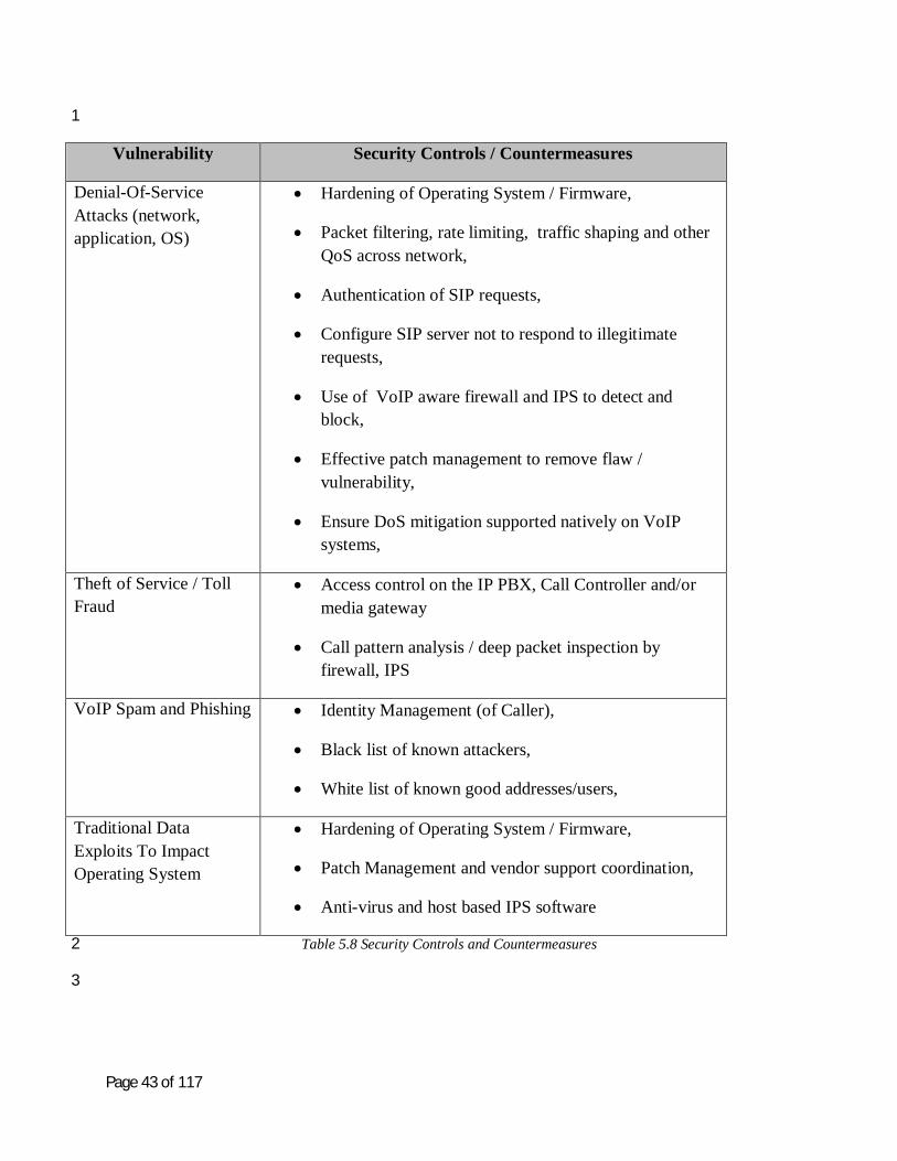
Page 43 of 117
1
Vulnerability Security Controls / Countermeasures
Denial-Of-Service Attacks (network, application, OS)
Hardening of Operating System / Firmware,
Packet filtering, rate limiting, traffic shaping and other QoS across network,
Authentication of SIP requests,
Configure SIP server not to respond to illegitimate requests,
Use of VoIP aware firewall and IPS to detect and block,
Effective patch management to remove flaw / vulnerability,
Ensure DoS mitigation supported natively on VoIP systems,
Theft of Service / Toll Fraud
Access control on the IP PBX, Call Controller and/or media gateway
Call pattern analysis / deep packet inspection by firewall, IPS
VoIP Spam and Phishing Identity Management (of Caller),
Black list of known attackers,
White list of known good addresses/users,
Traditional Data Exploits To Impact Operating System
Hardening of Operating System / Firmware,
Patch Management and vendor support coordination,
Anti-virus and host based IPS software
Table 5.8 Security Controls and Countermeasures 2
3

Page 44 of 117
Table 5.9 summarizes recommended security controls to mitigate threat – vulnerability from the 1 perspective exploitation of the signalling, media and management plane. In general, the same 2 security controls can be applied across the various traffic planes. 3
4
Threat – Vulnerability
Mitigation Techniques Across Traffic Planes
Media Signalling / Control
Management
Configuration Weakness
Hardening OS/Firmware
Hardening OS/Firmware
Hardening OS/Firmware
Unauthorized Access - Weak Authentication
Strong Authentication
Strong Authentication
Strong Authentication
Malicious Code Anti-malware,
Anti-Virus
Anti-malware,
Anti-Virus
Anti-malware,
Anti-Virus
Reconnaissance and Enumeration
Hardening OS/Firmware
Firewall, ACLs
Hardening OS/Firmware
Firewall, ACLs,
SIP over TLS
Hardening OS/Firmware
Firewall, ACLs,
Secure mgmt channel
Spoofing Secure RTP SIP over TLS Secure mgmt channel
Eavesdropping Secure RTP SIP over TLS Secure mgmt channel
Signalling And Media Manipulation
Strong Authentication,
Encryption
Strong Authentication,
Encryption
Strong Authentication,
Encryption
Fuzzing VoIP aware firewall VoIP aware firewall, Security code reviews with
vulnerability testing
OS / Firmware Hardening
5

Page 45 of 117
1
Threat – Vulnerability
Mitigation Techniques Across Traffic Planes
Media Signalling / Control
Management
Impersonation Strong Authentication
Strong Authentication
Strong Authentication
Man-In-The-Middle Attacks
Strong Authentication,
Encryption
Strong Authentication,
Encryption
Strong Authentication,
Encryption
Denial-Of-Service Attacks
Network based mitigation
Network based mitigation
Toll Fraud Strong Authentication
Strong Authentication
Strong Authentication
VoIP Spam And Phishing
N/A Blacklisting Blacklisting
Traditional Data Exploits To Impact Operating System
OS Hardening,
Patch Management
OS Hardening,
Patch Management
OS Hardening,
Patch Management
Table 5.9 Mitigation Techniques Applied Across Traffic Planes 2
3
Based on the results formulated in table 5-7 depicting the most critical impact – most likely 4 threat vulnerabilities for each asset, table 5-10 identifies recommended security controls to 5 protect and mitigate against them. This is not an exhaustive list of security controls and 6 countermeasures to implement for each asset, but simply a general set of controls in support of 7 the VoIP Reference Architecture. 8
9

Page 46 of 117
1
System
Asset
Informational Asset
Most Likely Threat-Vulnerabilities
Security Controls - Mitigation
IP Phone Handset
Operating System Enumeration OS/Firmware Hardening
Configuration Weak Authentication Strong Authentication and Identity Management
Media DoS Attack OS/Firmware Hardening
Signalling Eavesdropping SIP over TLS
Management Eavesdropping Secure mgmt channel
System
Asset
Informational Asset
Most Likely Threat-Vulnerabilities
Security Controls - Mitigation
Desktop Operating System Malicious Code, Enumeration
OS/Firmware Hardening
VoIP Application (i.e., Soft phone)
Configuration Weakness
Strong Authentication and Identity Management
Media DoS Attack OS/Firmware Hardening
Signalling Eavesdropping SIP over TLS
Management Weak Authentication Secure mgmt channel
2

Page 47 of 117
1
System
Asset
Informational Asset
Most Likely Threat-Vulnerabilities
Security Controls - Mitigation
Call Controller and Media Gateway (or IP PBX)
Operating System Enumeration OS/Firmware Hardening
Configuration Configuration Weakness
Strong Authentication and Identity Management
Dial Plan Theft of Service / Toll Fraud
Strong Authentication and Identity Management
Call Detail Records (and Billing Info)
Weak Authentication, Configuration
Weakness
Strong Authentication and Identity Management
Software Licenses DoS Attacks DoS Mitigation
Media DoS Attack OS/Firmware Hardening, Network
based DoS Mitigation
Signalling Eavesdropping and Impersonation
SIP over TLS
Management Weak Authentication Secure mgmt channel
System
Asset
Informational Asset
Most Likely Threat-Vulnerabilities
Security Controls - Mitigation
Element Manager
Operating System Malicious Code, Enumeration
OS/Firmware Hardening
Configuration and Management
Weak Authentication Strong Authentication , Secure mgmt
channel
2

Page 48 of 117
1
System
Asset
Informational Asset
Most Likely Threat-Vulnerabilities
Security Controls - Mitigation
Network (i.e., router, switch, firewall, VPN, IPS)
OS / Firmware Enumeration OS/Firmware Hardening
Signalling Eavesdropping Encryption
Media DoS Attack DoS Mitigation
Management Eavesdropping Encryption
System
Asset
Informational Asset
Most Likely Threat-Vulnerabilities
Security Controls - Mitigation
DNS, DHCP, TFTP, RADIUS
Operating System Malicious Code, Enumeration
OS/Firmware Hardening
User Identification (i.e., IP Address)
DoS Attacks (i.e., DHCP exhaustion)
DoS Mitigation
User Profiles Weak Authentication, Configuration
Weakness
Strong Authentication and Identity Management
Configurations (i.e., Phones)
Weak Authentication,
Configuration Weakness
Strong Authentication and Identity Management
Table 5.10 Mitigation Techniques For Most Likely Threat Vulnerabilities 2
Summary 3
A security risk assessment can be a very lengthy, detailed process that may require several 4 iterations before the organization is ready to implement the necessary security controls to protect 5 its operations, assets and overall voice services. Section 5 is meant to provide an understanding 6 of how to develop a security risk assessment (or threat risk analysis) for a VoIP deployment. 7 The assessment developed in this section will be used in Section 6 to establish a security 8 checklist for the VoIP Reference Architecture that can be translated into a Security Content 9 Automation Protocol (SCAP) benchmark. 10
11

Page 49 of 117
Chapter 6 - VoIP Security Checklist and Mapping to SP 800-53 R3 1 2
Purpose 3
The purpose of this section is to establish a high level security checklist for the VoIP solution 4 described previously in this document. The intent is not to produce a vendor specific set of 5 requirements, such as that appropriate for system-specific controls or hybrid controls1, but rather 6 to specify a minimum set of security requirements for a generic VoIP solution. 7
8
“Security controls not designated as common controls are considered system-specific controls or 9 hybrid controls. System-specific controls are the primary responsibility of information system 10 owners and their respective authorizing officials. Organizations assign a hybrid status to a 11 security control when one part of the control is deemed to be common and another part of the 12 control is deemed to be system-specific.” 13
This minimum set of security requirements could then be used by a VoIP solution provider to 14 create a vendor specific lower level security checklist, consistent with the system-specific control 15 guidance in SP 800-53-R3, that can be translated into a tailored, hybrid set of controls consistent 16 with the framework set forth in the Security Content Automation Protocol (SCAP) benchmark 17
18
Checklist 19
A security checklist is a prose description of the steps that are required to be taken to configure a 20 product to ensure that it is operating in a secure manner. This is generally known as a 21 “hardening” of a product into a secure configuration appropriate for that product. 22
23
The VoIP security checklist will be written according to the specifications of the NIST Special 24 Publication 800-70-R1 National Checklist Program for IT Products – Guidelines for Checklist 25 Users and Developers. The National Checklist Program (NCP) is a NIST program that hosts 26 product security checklists. These are intended to be used to develop SCAP content (i.e. data 27 streams) that can be used by SCAP validated tools to verify the product configuration). 28
29
1 NIST Special Publication (SP) 800-53-R3, August 2009, paragraph 2.3 Common Controls, page 11.

Page 50 of 117
SCAP 1
The Security Content Automation Protocol (SCAP) program is a NIST validation program that 2 allows scanning tools to be validated using SCAP content. These tools are then used to scan 3 products to verify that they are in the security configuration designated by the checklist. SCAP 4 uses a set of six open standards working together to standardize a method of determining a 5 product’s configuration settings and vulnerability / patch status. The US federal government 6 requires that every agency use an SCAP validated tool to show FISMA compliance. Currently, 7 the focus of SCAP is the Federal Desktop Core Configuration (FDCC) requirements for 8 Microsoft XP and Vista platforms as prescribed by the Office of Management and Budget 9 (OMB). Because FAR 38 requiring the use of NCP checklists was published in March 2008, the 10 need for SCAP data streams for each product has intensified. The ultimate goal of this section is 11 to demonstrate that SCAP data stream(s) can be written, and further refined through appropriate 12 tailoring as indicated, for a VoIP solution. 13
14
SCAP data streams are usually developed on a product basis. One challenge for the VoIP 15 solution is to determine a security checklist for what is essentially a system. This is not unlike a 16 certification and authorization activity. A second challenge is to ensure that this baseline security 17 is generic enough and extensible enough to allow both differences in solution types and 18 innovations in future solutions. The SCAP baseline security checklist is not presently based on a 19 specific set of standards, but rather on industry best-practices. There are other initiatives that are 20 incorporating VoIP solutions (e.g. DISA for use in the DoD) for which this baseline checklist 21 can be used. Specific solutions and/or requirements are not within scope of this paper, but it is 22 intended to provide a generic VoIP solution and can be modified to suit other system-specific 23 controls that are more appropriate for diverging VoIP vendor proprietary solutions, and reflect 24 areas where more convergence in future products would accomplish the goal of building-in 25 security by commercial interests. The checklist will then be able to enhance designed-in security 26 while allowing each solution provider to focus on the converging solution strategies that they 27 agree will afford the capability to achieve the SCAP goals over time, with attendant refinements 28 in their product as well as through the establishment of verifiable and measurable checklist 29 compliance tools that fit suit each vendor’s tailored SCAP approach and solution. 30
31
The security checklist incorporates the reference architecture set forth in Section 4 of this paper. 32 The architecture is discussed here in terms of subsystems that provide specific security 33 functionality. The environment is also briefly discussed in the following paragraphs. The purpose 34 of the threat scenario description is to identify threats that need to be countered or mitigated to 35 ensure a secure configuration of the VoIP solution. The mitigations, or controls, are then mapped 36 to the controls found in the NIST SP 800-53-R3 Security Controls. 37

Page 51 of 117
1
VoIP Solution Architecture and Subsystems 2
The reference architecture, upon which the security checklist is based, is vendor agnostic. There 3 will be differences in implementation of protocols, software/firmware/hardware types and 4 specialty features between solutions. The baseline is intended to give a minimum set of 5 requirements for any VoIP solution which the vendor can tailor to suit their unique proprietary 6 solution. This is felt to be a development path that may still afford future reliance upon common 7 controls as the proprietary portions are re-engineered to be interoperable where they are not so 8 today. The benefit encourages standardization growth to be more VoIP solution diverse, yet 9 friendly and mutually inclusive, not exclusive. Through vendor implementations that are initially 10 tolerant of system-specific components, it is hoped that future evolutionary VoIP growth towards 11 common controls will permit them to be better integrated into larger system architectural 12 solutions. 13
14
Prior to discussion of the functional subsystems of the VoIP solution, some operational and 15 procedural assumptions are made. This will likely be refined as this endeavour progresses but for 16 this paper the following assumptions are made: 17
18
1. The VoIP solution will be integrated into a data network. 19 2. A VoIP VLAN will be implemented in the solution. 20 3. Any PC operating systems that fall under the OMB requirement for FDCC compliance 21
will be FDCC compliant and the relevant FDCC SCAP data stream will be used in 22 conjunction with any SCAP data stream derived from this checklist. 23
4. Vendors using proprietary operating systems in the solution will be required to produce 24 the appropriate checklist and SCAP data stream for the OS. Current FDCC compliant 25 operating systems will be used as a guide for the development of said data streams and 26 these will be used in conjunction with any data streams derived from the VoIP checklist. 27
5. Since the VoIP solution is integrated into an existing data network, it is assumed that the 28 network will provide appropriate security controls to protect the network. 29
6. Security checklists require a mapping to relevant standards and this checklist will use the 30 NIST SP 800-53 R3 9(Security Controls) as the standard to which it maps. In the future it 31 is anticipated that the mapping scope will broaden to include other relevant standards. 32
7. Every security checklist conforming to the NCP requirements must discuss a threat 33 scenario. This checklist is based on the Managed Environment scenario in SP 800-70-34 R1.The threat scenario is been discussed in depth in section 5 of this paper, and the 35 results of the threat scenario discussion will be used in this section. 36
8. The Managed Environment scenario must include a discussion on insider threats. This is 37 discussed in section 4 but there is no intention to include any specific procedural 38 mitigation in this checklist though such mitigations are highly advised. Physical security 39

Page 52 of 117
procedures and protections are not within scope for the security checklist though these 1 are highly advisable. 2
9. Some well defined components of a VoIP solution are also expected to be manifest as 3 part of a data network, and where these shared converged components are extant it is 4 presumed that they will be “hardened,” or at least provisioned with an appropriate level 5 of protection for the most sensitive content of both the data network and the VoIP content 6 borne over the same infrastructure.. These components are neither enumerated nor 7 discussed in the checklist, but they are seen to include such elements as a DNS server, a 8 DHCP server, NTP server, etc. Required security functionality expectations from these 9 data network components are only cited when there are parallel VoIP specific 10 configuration needs that bear consideration and inclusive treatment. 11
12
VoIP Subsystems 13
There are four defined subsystems for the VoIP reference architecture for the purposes of this 14 paper. They are: 15
1. The Call Controller Subsystem 16
2. The Element Manager Subsystem 17
3. The IP Phone Subsystem 18
4. The SIP Aware Firewall and IPS Subsystem 19
The purpose of each subsystem will be discussed and the security functionality expected to be 20 provided by the subsystem will be given. This functionality will then be mapped to the security 21 controls in SP 800-53 R3. The intent is to describe what functionality is required without 22 prescribing how it must be implemented. This is left to the individual vendor to make the 23 checklist more granular to suit their specific solution. 24
25
26

Page 53 of 117
The Call Controller Subsystem 1
2
3
Figure 6.1 – The Call Controller Subsystem. 4
The Call Controller Subsystem can be further divided into specific functional areas. These have 5 been identified as: 6
1. Call Controller to IP Phones Functional Area 7
2. Call Controller to Media Gateway Functional Area 8
3. Call Controller to Element Manager Functional Area 9
4. Call Controller to Call Controller Functional Area 10
It should be noted here that the Call Controller to Voice Mail and Application Server functional 11 areas are out of scope for this document and will not be discussed at this time. Each of the 12 covered functional areas are discussed in terms of the connectivity, purpose and security 13 functionality required by that functional area. 14
15
16

Page 54 of 117
The Call Controller to IP Phones Funtional Area 1
2
3
Figure 6.2 – The Call Controller to IP Phones Functional Area 4
5
Connectivity of the Functional Area 6
The Call Controller connects to the IP Phones via the VoIP VLAN and the same physical LAN 7 as the data network. 8
Purpose of the Functional Area Components 9
The main purpose of the Call Controller is to handle VoIP SIP signalling such as registering 10 users, keeping track of registered users, users’ locations, and establishing and terminating media 11 sessions. The Call Controller also serves as a VoIP media proxy (forwarding RTP/SRTP packets 12 on conference calls and similar functions), allowing users to check call logs and access their 13 contacts, and pushing configuration and firmware files to the IP phones. 14
15
Security Functionality Required by the Functional Area 16
Security functionality specifically required to be implemented in this Functional Area of the Call 17 Controller Subsystem consists of: 18
1. Endpoint registration 19
2. Location discovery (DNS) 20
3. Signalling session establishment and termination management 21
4. Session and media proxy (voicemail, conferencing) 22
5. Dial plan management 23

Page 55 of 117
6. Call admission control 1
7. Phone firmware management 2
8. Endpoint configuration management 3
9. CDR creation 4
5

Page 56 of 117
1
The Call Controller to Media Gateway Functional Area 2
3
4
Figure 6.3 - The Call Controller to Media Gateway Functional Area 5
The Connectivity of the Functional Area 6
7
It is anticipated that this will be a physically separated network used to carry MGCP or H.248 8 messages. It is also anticipated that IPSec will be implemented. 9
The Purpose of the Functional Area 10
11
The main purpose is to handle VoIP signalling using MGCP or H.248 such as establishing and 12 terminating media sessions and keeping track of established sessions. 13
The Security Functionality Required by the Functional Area 14
15
Security functionality specifically required to be implemented in this Functional area of the Call 16 Controller Subsystem consists of: 17
1. Registration with device and user authentication 18

Page 57 of 117
2. Location discovery using DNS 1
3. Session creation and termination management 2
4. Session and media proxy 3
5. Call admission control 4
6. Phone firmware management 5
7. Dial plan management 6
8. Management of endpoint configuration 7
9. PSTN routing 8
10. Emergency services 9
11. CDR creation 10
11
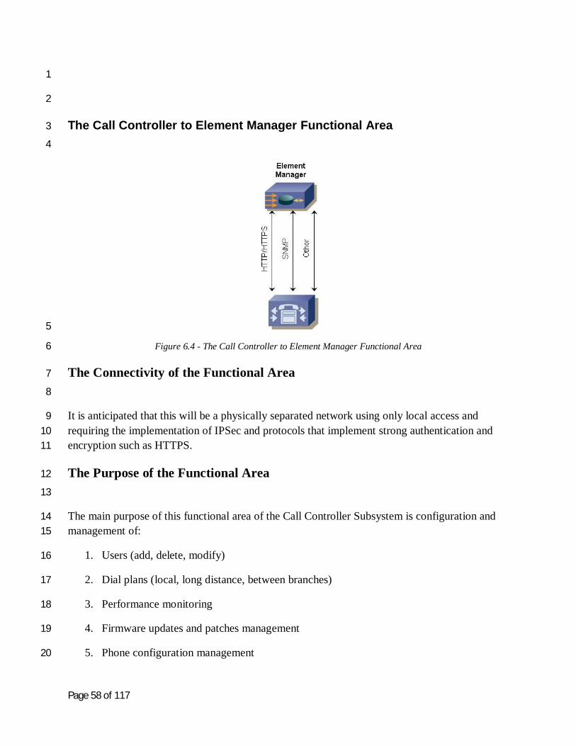
Page 58 of 117
1
2
The Call Controller to Element Manager Functional Area 3
4
5
Figure 6.4 - The Call Controller to Element Manager Functional Area 6
The Connectivity of the Functional Area 7
8
It is anticipated that this will be a physically separated network using only local access and 9 requiring the implementation of IPSec and protocols that implement strong authentication and 10 encryption such as HTTPS. 11
The Purpose of the Functional Area 12
13
The main purpose of this functional area of the Call Controller Subsystem is configuration and 14 management of: 15
1. Users (add, delete, modify) 16
2. Dial plans (local, long distance, between branches) 17
3. Performance monitoring 18
4. Firmware updates and patches management 19
5. Phone configuration management 20

Page 59 of 117
6. Backup and restore 1
2
The Security Functions Required by the Functional Area 3
4
Security functionality specifically required to be implemented in this functional area of the Call 5 Controller Subsystem consists of: 6
1. Location discovery 7
2. Session creation and termination management 8
9
10
The Call Controller to Call Controller Functional Area 11
12
13
Figure 6.5 - The Call Controller to Call Controller Functional Area 14
The Connectivity of the Functional Area 15
16
It is anticipated that this will be physically separated networks requiring the implementation of 17 IPSec and protocols that implement strong authentication and encryption such as HTTPS. 18
19
The Purpose of the Functional Area 20
21
The main purpose of this functional are of the Call Controller Subsystem is to provide 22 redundancy, load balancing and inter-branch communication. 23
24

Page 60 of 117
The Security Functionality Required by the Functional Area 1
Security functionality specifically required to be implemented in this functional area of the Call 2 Controller Subsystem consists of: 3
1. Authentication of Call Controller 4
2. Location discovery 5
3. Session creation and termination management 6
7
8
9
10

Page 61 of 117
The Element Manager Subsystem 1
2
3
Figure 6.6 – The Element Manager Subsystem 4
5
The Element Manager Subsystem usually consists of a graphical configuration tool that helps to 6 simplify or streamline the management and provisioning processes for different types of devices 7 such as gateways, firewalls and Call Controllers. 8
9
The Connectivity of the Subsystem 10
11
It is anticipated that this will be a physically separated network using local access only and 12 requiring the implementation of IPSec and protocols that implement strong authentication and 13 encryption such as HTTPS. 14
15
16

Page 62 of 117
The Purpose of the Subsystem 1
2
The main purpose of the Element Manager Subsystem is configuration and management of: 3
1. Users (add, delete, modify) 4
2. Performance monitoring 5
3. Firmware updates and patches management 6
4. Device specific features configuration 7
5. Backup and restore 8
9
The Security Functions Required by the Subsystem 10
11
Security functionality specifically required to be implemented in the Element Manager 12 Subsystem consists of: 13
1. Strong authentication for administrators 14
2. Authorization 15
3. Encryption and integrity 16
4. Confidentiality 17
18
19
20

Page 63 of 117
The IP Phone Subsystem 1
2
3
Figure 6.7 – The IP Phones Subsystem 4
The IP Phone Subsystem can be further divided into specific functional areas. These have been 5 identified as: 6
1. The IP Phone to Call Controller Functional Area 7
2. The IP Phone to Media Gateway Functional Area 8
3. The IP Phone to IP Phone Functional Area 9
4. The IP Phone to User Functions Functional Area 10
11
The IP Phone to Call Controller Functional Area 12
13
14
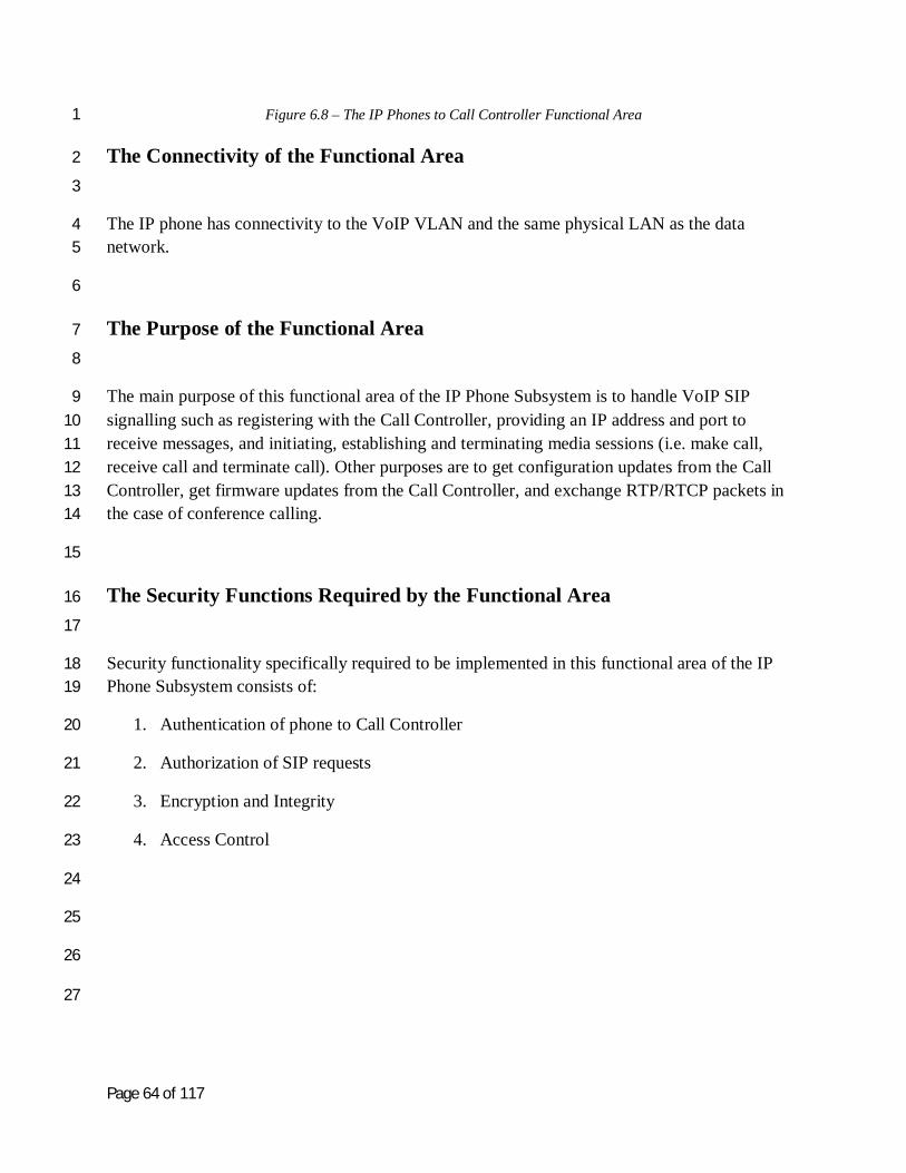
Page 64 of 117
Figure 6.8 – The IP Phones to Call Controller Functional Area 1
The Connectivity of the Functional Area 2
3
The IP phone has connectivity to the VoIP VLAN and the same physical LAN as the data 4 network. 5
6
The Purpose of the Functional Area 7
8
The main purpose of this functional area of the IP Phone Subsystem is to handle VoIP SIP 9 signalling such as registering with the Call Controller, providing an IP address and port to 10 receive messages, and initiating, establishing and terminating media sessions (i.e. make call, 11 receive call and terminate call). Other purposes are to get configuration updates from the Call 12 Controller, get firmware updates from the Call Controller, and exchange RTP/RTCP packets in 13 the case of conference calling. 14
15
The Security Functions Required by the Functional Area 16
17
Security functionality specifically required to be implemented in this functional area of the IP 18 Phone Subsystem consists of: 19
1. Authentication of phone to Call Controller 20
2. Authorization of SIP requests 21
3. Encryption and Integrity 22
4. Access Control 23
24
25
26
27

Page 65 of 117
The IP Phone to Media Gateway Functional Area 1
2
3
Figure 6.9 - The IP Phone to Media Gateway Functional Area 4
The Connectivity of the Functional Area 5
6
This functional area of the IP Phone Subsystem has connectivity to the VoIP VLAN and the data 7 network. 8
9
The Purpose of the Functional Area 10
11
The main purpose of this functional area of the IP Phone Subsystem is to handle RTP and RTCP 12 packets for external calls. 13
14

Page 66 of 117
The Security Functions Required by the Functional Area 1
2
Security functionality specifically required to be implemented in this element of the IP Phone 3 Subsystem consists of: 4
1. Availability; and, 5
2. Confidentiality by RTP encryption (if used) 6
7
8
The IP Phone to IP Phone Functional Area 9
10
Figure 6.10 - The IP Phone to IP Phone Functional Area 11
The Connectivity of the Functional Area 12
13
This functional are of the IP Phone Subsystem has connectivity to the VoIP VLAN and the data 14 network. 15
16
The Purpose of the Functional Area 17
18
The main purpose of this element of the IP Phone Subsystem is to handle a media session by 19 receiving and decoding RTP packets, encoding and sending RTP packets, and handling RTP 20 control messages. 21
22
The Security Functions Required by the Functional Area 23
24
Security functionality specifically required to be implemented in this functional area of the IP 25 Phone Subsystem consists of: 26

Page 67 of 117
Confidentiality by RTP encryption 1
2
The IP Phone to User Functional Area 3
4
5
Figure 6.11 - The IP Phone to User Functional Area 6
The Connectivity of the Functional Area 7
8
This functional area of the IP Phone Subsystem has connectivity to the same physical data 9 network and also has a manual aspect. 10
11
The Purpose of the Functional Area 12
13
The main purpose of this functional are of the IP Phone Subsystem is configuration and usage of 14 the IP phone such as reconfiguring the phone using special key combinations, making and 15 receiving calls, and remote management using HTTPS for reconfiguration of the phone. 16
17
The Security Function Requirements of the Functional Area 18
19
Security functionality specifically required to be implemented in this functional area of the IP 20 Phone Subsystem consists of: 21
Confidentiality by RTP encryption 22
23
24
25
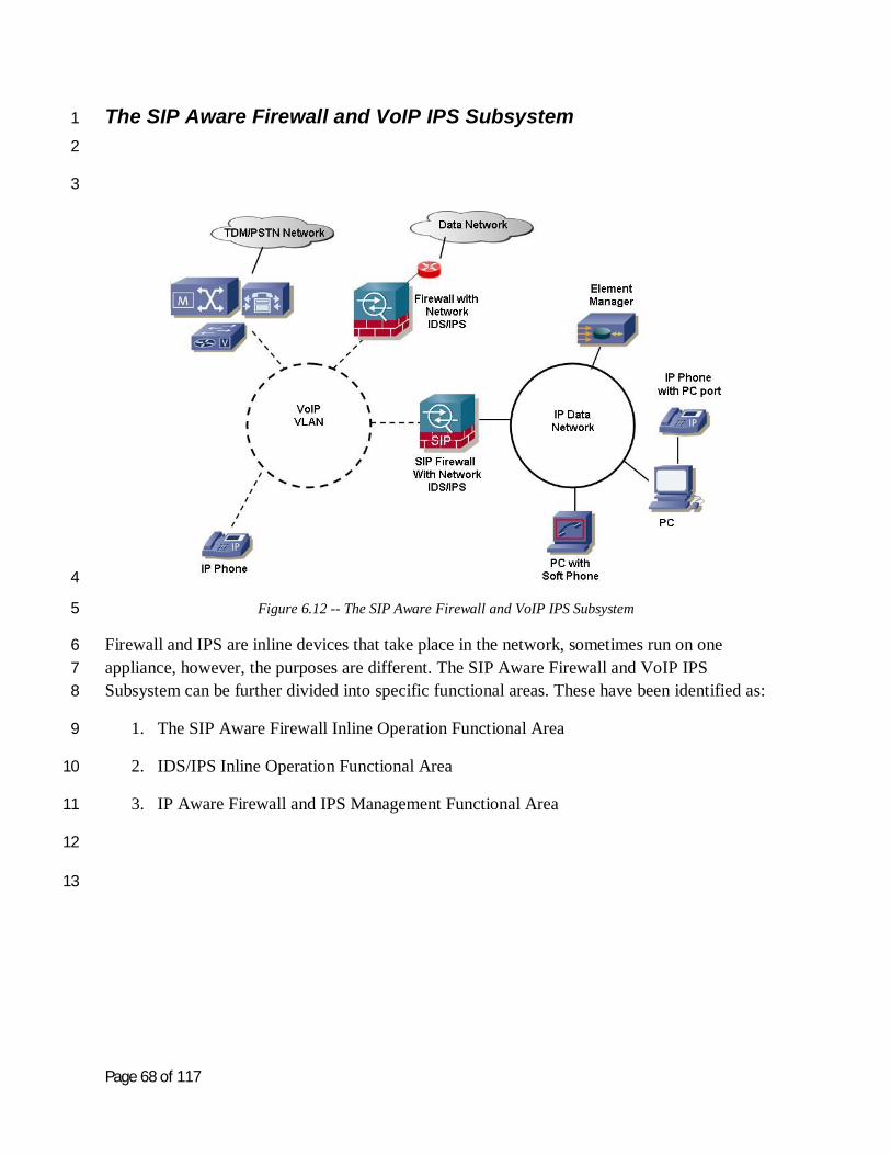
Page 68 of 117
The SIP Aware Firewall and VoIP IPS Subsystem 1
2
3
4
Figure 6.12 -- The SIP Aware Firewall and VoIP IPS Subsystem 5
Firewall and IPS are inline devices that take place in the network, sometimes run on one 6 appliance, however, the purposes are different. The SIP Aware Firewall and VoIP IPS 7 Subsystem can be further divided into specific functional areas. These have been identified as: 8
1. The SIP Aware Firewall Inline Operation Functional Area 9
2. IDS/IPS Inline Operation Functional Area 10
3. IP Aware Firewall and IPS Management Functional Area 11
12
13

Page 69 of 117
The SIP Aware Firewall Inline Operation Functional Area 1
2
3
Figure 6.13 -- The SIP Aware Firewall Inline Operation Functional Area 4
The Connectivity of the Functional Area 5
6
The SIP aware firewall is inline between the data network and the VoIP VLAN. 7
8
9

Page 70 of 117
The Purpose of the Functional Area 1
2
The main purpose of this functional area of the SIP Aware Firewall and VoIP IPS Subsystem is 3 to provide firewall functionality. The firewall opens “pinholes” for RTP/RTCP packets based on 4 SIP signalling. The firewall provides stateful SIP signalling inspection, closes all unnecessary 5 ports and opens dynamic RTP/RTCP ports. 6
7
The Security Function Requirements of the Functional Area 8
9
Security functionality specifically required to be implemented in this functional area of the SIP 10 Aware Firewall and VoIP IPS Subsystem consists of: 11
1. Security Audit 12
2. Non-repudiation 13
14
15
16

Page 71 of 117
The IDS/IPS Inline Operation Functional Area 1
2
3
Figure 6.14 -- The IDS/IPS Inline Operation Functional Area 4
The Connectivity of the Functional Area 5
6
The IDS/IPS is inline between the data network and the VoIP VLAN. 7
8
9
Page 72 of 117
The Purpose of the Functional Area 1
2
The main purpose of this funcational area of the SIP Aware Firewall and VoIP IPS Subsystem is 3 to provide IPS/IDS functionality. The IDS/IPS detects and prevents attacks on the VoIP server 4 components by performing malicious attack detection, known attacks detection, behavior based 5 anomalies detection, SPIT detection, and DoS prevention. 6
7
The Security Function Requirements of the Functional Area 8
9
Security functionality specifically required to be implemented in this functional area of the SIP 10 Aware Firewall and VoIP IPS Subsystem consists of: 11
1. Security Audit 12
2. Availability 13
3. Non-repudiation 14
15
16

Page 73 of 117
The SIP Aware Firewall and IPS Management Functional Area 1
2
Figure 6.15 - The SIP Aware Firewall and IPS Management Functional Area 3
The Connectivity of the Functional Area 4
5
It is anticipated that there will be physical network separation (i.e. using only local access), 6 implementing IPSec, and using strong authentication and encryption protocols such as HTTPS. 7
8
The Purpose of the Functional Area 9
10
The main purpose of this functional are of the SIP Aware Firewall and VoIP IPS Subsystem is 11 configuration and management of the firewall, performance monitoring, and firmware updates 12 and patches. 13
14

Page 74 of 117
The Security Function Requirements of the Functional Area 1
2
Security functionality specifically required to be implemented in this functional are of the SIP 3 Aware Firewall and VoIP IPS Subsystem consists of: 4
1. Security Audit 5
2. Authentication of administrators and users 6
3. Authorization 7
8
9
10

Page 75 of 117
Mapping of Functionality to SP 800-53 R3 Controls 1
2
Having determined the essential security functionality for the checklist, the appropriate controls 3 to be implemented can be determined and matched to the security functionality provided by the 4 VoIP solution. 5
6
Call Controller Subsystem
Call Controller to IP Phones
Security Function
SP 800-53 R3 Control
Low Moderate High
Endpoint registration
AC-2 AC-2 AC-2 (1), (2), (3), (4), (5), (6)
AC-2 (1), (2), (3), (4), (5), (6)
AC-3 AC-3 AC-3 AC-3
AC-4 AC-4 AC-4 AC-4
AC-7 AC-7 AC-7 AC-7
AC-10 AC-10
Not selected
AC-10
Not selected
AC-10
AC-11 AC-11
Not selected
AC-11 AC-11
AU-8 AU-8 AU-8 (1) AU-8 (1)
AU-9 AU-9 AU-9 AU-9
AU-10 AU-10
Not Selected
AU-10
Not Selected
AU-10
AU-12 AU-12 AU-12 AU-12 (1)

Page 76 of 117
IA-2 IA-2 (1) IA-2 (2) IA-2 (3)
IA-3 IA-3
Not Selected
IA-3 IA-3
IA-6 IA-6 IA-6 IA-6
IA-8 IA-8 IA-8 IA-8
SI-7 SI-7
Not Selected
SI-7
Not Selected
SI-7 (1), (2)
SI-11 SI-11
Not Selected
SI-11 SI-11
SC-8 SC-8
Not Selected
SC-8 (1) SC-8 (1)
SC-9 SC-9
Not Selected
SC-9 (1) SC-9 (1)
SC-10 SC-10
Not Selected
SC-10 SC-10
SC-23 SC-23
Not Selected
SC-23 SC-23
Location discovery (DNS)
SC-20 SC-20 (1) SC-20 (1) SC-20 (1)
SC-21 SC-21
Not selected
Not selected SC-21
Signalling SC-8 SC-8 SC-8 (1) SC-8 (1)
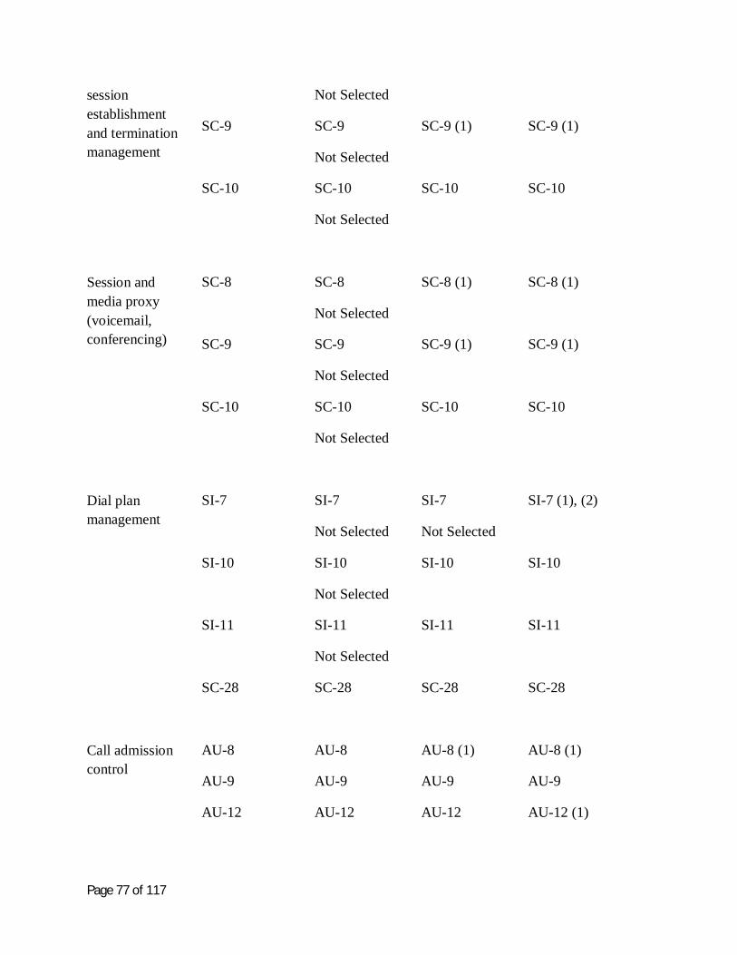
Page 77 of 117
session establishment and termination management
Not Selected
SC-9 SC-9
Not Selected
SC-9 (1) SC-9 (1)
SC-10 SC-10
Not Selected
SC-10 SC-10
Session and media proxy (voicemail, conferencing)
SC-8 SC-8
Not Selected
SC-8 (1) SC-8 (1)
SC-9 SC-9
Not Selected
SC-9 (1) SC-9 (1)
SC-10 SC-10
Not Selected
SC-10 SC-10
Dial plan management
SI-7 SI-7
Not Selected
SI-7
Not Selected
SI-7 (1), (2)
SI-10 SI-10
Not Selected
SI-10 SI-10
SI-11 SI-11
Not Selected
SI-11 SI-11
SC-28 SC-28 SC-28 SC-28
Call admission control
AU-8 AU-8 AU-8 (1) AU-8 (1)
AU-9 AU-9 AU-9 AU-9
AU-12 AU-12 AU-12 AU-12 (1)

Page 78 of 117
Phone firmware management
SI-7 SI-7
Not Selected
Not Selected SI-7 (1), (2)
SI-10 SI-10
Not Selected
SI-10 SI-10
SI-11 SI-11
Not Selected
SI-11 SI-11
SC-23 SC-23
Not Selected
SC-23 SC-23
Endpoint configuration management
SI-7 SI-7
Not Selected
Not Selected SI-7 (1), (2)
SI-10 SI-10
Not Selected
SI-10 SI-10
SI-11 SI-11
Not Selected
SI-11 SI-11
SC-23 SC-23
Not Selected
SC-23 SC-23
CDR creation SC-28 SC-28 SC-28 SC-28
Table 6.1a1

Page 79 of 117
1
Call Controller Subsystem
Call Controller to Media Gateway
Security Function
SP 800-53 R3 Control
Low Moderate High
Registration with device / user authentication
AC-2 AC-2 AC-2 (1), (2), (3), (4), (5), (6)
AC-2 (1), (2), (3), (4), (5), (6)
AC-3 AC-3 AC-3 AC-3
AC-4 AC-4 AC-4 AC-4
AC-7 AC-7 AC-7 AC-7
AC-10 AC-10
Not selected
AC-10
Not selected
AC-10
AC-11 AC-11
Not selected
AC-11 AC-11
AU-8 AU-8 AU-8 (1) AU-8 (1)
AU-9 AU-9 AU-9 AU-9
AU-12 AU-12 AU-12 AU-12 (1)
AU-12 AU-12 AU-12 AU-12 (1)
IA-2 IA-2 (1) IA-2 (2) IA-2 (3)
IA-3 IA-3
Not Selected
IA-3 IA-3
IA-6 IA-6 IA-6 IA-6
IA-8 IA-8 IA-8 IA-8

Page 80 of 117
SI-7 SI-7
Not Selected
SI-7
Not Selected
SI-7 (1), (2)
SI-11 SI-11
Not Selected
SI-11 SI-11
SC-8 SC-8
Not Selected
SC-8 (1) SC-8 (1)
SC-9 SC-9
Not Selected
SC-9 (1) SC-9 (1)
SC-10 SC-10
Not Selected
SC-10 SC-10
SC-23 SC-23
Not Selected
SC-23 SC-23
Location discovery using DNS
SC-20 SC-20 (1) SC-20 (1) SC-20 (1)
SC-21 SC-21
Not selected
SC-21
Not selected
SC-21
Session creation and termination management
SC-8 SC-8
Not Selected
SC-8 (1) SC-8 (1)
SC-9 SC-9
Not Selected
SC-9 (1) SC-9 (1)
SC-10 SC-10 SC-10 SC-10

Page 81 of 117
Not Selected
Session and media proxy
SC-8 SC-8
Not Selected
SC-8 (1) SC-8 (1)
SC-9 SC-9
Not Selected
SC-9 (1) SC-9 (1)
SC-10 SC-10
Not Selected
SC-10 SC-10
Call admission control
AU-8 AU-8 AU-8 (1) AU-8 (1)
AU-9 AU-9 AU-9 AU-9
AU-12 AU-12 AU-12 AU-12 (1)
Phone firmware management
SI-7 SI-7
Not Selected
Not Selected SI-7 (1), (2)
SI-10 SI-10
Not Selected
SI-10 SI-10
SI-11 SI-11
Not Selected
SI-11 SI-11
Dial plan management
SI-7 SI-7
Not Selected
SI-7
Not Selected
SI-7 (1), (2)
SI-10 SI-10
Not Selected
SI-10 SI-10

Page 82 of 117
SI-11 SI-11
Not Selected
SI-11 SI-11
Management of endpoint configuration
SI-7 SI-7
Not Selected
Not Selected SI-7 (1), (2)
SI-10 SI-10
Not Selected
SI-10 SI-10
SI-11 SI-11
Not Selected
SI-11 SI-11
SC-28 SC-28 SC-28 SC-28
PSTN routing SI-7 SI-7
Not Selected
SI-7
Not Selected
SI-7 (1), (2)
SI-10 SI-10
Not Selected
SI-10 SI-10
SI-11 SI-11
Not Selected
SI-11 SI-11
Emergency services
CDR creation SC-28 SC-28 SC-28 SC-28
Table 6.1b1

Page 83 of 117
1
Call Controller Subsystem
Call Controller to Element Manager
Security Function
SP 800-53 R3 Control
Low Moderate High
Location discovery
SC-20 SC-20 (1) SC-20 (1) SC-20 (1)
SC-21 SC-21
Not selected
SC-21
Not selected
SC-21
Session creation and termination management
SC-8 SC-8
Not Selected
SC-8 (1) SC-8 (1)
SC-9 SC-9
Not Selected
SC-9 (1) SC-9 (1)
SC-10 SC-10
Not Selected
SC-10 SC-10
Table 6.1c 2
Call Controller Subsystem
Call Controller to Call Controller
Security Function
SP 800-53 R3 Control
Low Moderate High
Authentication of Call Controller
AC-2 AC-2 AC-2 (1), (2), (3), (4), (5), (6)
AC-2 (1), (2), (3), (4), (5), (6)
AC-3 AC-3 AC-3 AC-3
AC-4 AC-4 AC-4 AC-4
AC-7 AC-7 AC-7 AC-7
AC-10 AC-10 AC-10 AC-10

Page 84 of 117
Not selected Not selected
AC-11 AC-11
Not selected
AC-11 AC-11
AU-8 AU-8 AU-8 (1) AU-8 (1)
AU-9 AU-9 AU-9 AU-9
AU-12 AU-12 AU-12 AU-12 (1)
AU-12 AU-12 AU-12 AU-12 (1)
IA-2 IA-2 (1) IA-2 (2) IA-2 (3)
IA-3 IA-3
Not Selected
IA-3 IA-3
IA-6 IA-6 IA-6 IA-6
IA-8 IA-8 IA-8 IA-8
SI-7 SI-7
Not Selected
SI-7
Not Selected
SI-7 (1), (2)
SI-11 SI-11
Not Selected
SI-11 SI-11
SC-8 SC-8
Not Selected
SC-8 (1) SC-8 (1)
SC-9 SC-9
Not Selected
SC-9 (1) SC-9 (1)

Page 85 of 117
SC-10 SC-10
Not Selected
SC-10 SC-10
SC-23 SC-23
Not Selected
SC-23 SC-23
Location discovery
SC-20 SC-20 (1) SC-20 (1) SC-20 (1)
SC-21 SC-21
Not selected
SC-21
Not selected
SC-21
Session creation and termination management
SC-8 SC-8
Not Selected
SC-8 (1) SC-8 (1)
SC-9 SC-9
Not Selected
SC-9 (1) SC-9 (1)
SC-10 SC-10
Not Selected
SC-10 SC-10
Table 6.1d 1
Element Manager Subsystem
Security Function
SP 800-53 R3 Control
Low Moderate High
Strong authentication for administrators
IA-2 IA-2 (1) IA-2 (2) IA-2 (3)
IA-3 IA-3
Not Selected
IA-3 IA-3
IA-6 IA-6 IA-6 IA-6
IA-8 IA-8 IA-8 IA-8
2

Page 86 of 117
1
Authorization AC-2 AC-2 AC-2 (1), (2), (3), (4), (5), (6)
AC-2 (1), (2), (3), (4), (5), (6)
AC-3 AC-3 AC-3 AC-3
AC-4 AC-4 AC-4 AC-4
SI-7 SI-7
Not Selected
SI-7
Not Selected
SI-7 (1), (2)
SI-10 SI-10
Not Selected
SI-10 SI-10
SI-11 SI-11
Not Selected
SI-11 SI-11
Encryption and integrity
SC-8 SC-8
Not Selected
SC-8 (1) SC-8 (1)
SC-9 SC-9
Not Selected
SC-9 (1) SC-9 (1)
SC-10 SC-10
Not Selected
SC-10 SC-10
Confidentiality SC-28 SC-28 SC-28 SC-28
Table 6.2 2
3

Page 87 of 117
1
IP Phone Subsystem
IP Phone to Call Controller
Security Function
SP 800-53 R3 Control
Low Moderate High
Authentication of phone to Call Controller
IA-2 IA-2 (1) IA-2 (2) IA-2 (3)
IA-3 IA-3
Not Selected
IA-3 IA-3
IA-6 IA-6 IA-6 IA-6
IA-8 IA-8 IA-8 IA-8
Authorization of SIP requests
IA-3 IA-3
Not Selected
IA-3 IA-3
SI-7 SI-7
Not Selected
SI-7
Not Selected
SI-7 (1), (2)
Encryption and
Integrity
SC-8 SC-8
Not Selected
SC-8 (1) SC-8 (1)
SC-9 SC-9
Not Selected
SC-9 (1) SC-9 (1)
SC-28 SC-28 SC-28 SC-28
Access Control AC-2 AC-2 AC-2 (1), (2), (3), (4), (5), (6)
AC-2 (1), (2), (3), (4), (5), (6)
AC-3 AC-3 AC-3 AC-3
AC-4 AC-4 AC-4 AC-4
Table 6.3a 2
3

Page 88 of 117
1
IP Phone Subsystem
IP Phone to Media Gateway
Security Function
SP 800-53 R3 Control
Low Moderate High
Confidentiality by RTP encryption
SC-8 SC-8
Not Selected
SC-8 (1) SC-8 (1)
SC-9 SC-9
Not Selected
SC-9 (1) SC-9 (1)
Table 6.3b 2
IP Phone Subsystem
IP Phone to IP Phone
Security Function
SP 800-53 R3 Control
Low Moderate High
Confidentiality - RTP encryption
SC-8 SC-8
Not Selected
SC-8 (1) SC-8 (1)
SC-9 SC-9
Not Selected
SC-9 (1) SC-9 (1)
Table 6.3c 3
4
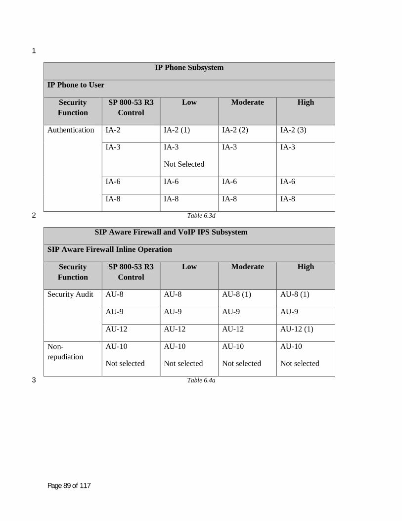
Page 89 of 117
1
IP Phone Subsystem
IP Phone to User
Security Function
SP 800-53 R3 Control
Low Moderate High
Authentication IA-2 IA-2 (1) IA-2 (2) IA-2 (3)
IA-3 IA-3
Not Selected
IA-3 IA-3
IA-6 IA-6 IA-6 IA-6
IA-8 IA-8 IA-8 IA-8
Table 6.3d 2
SIP Aware Firewall and VoIP IPS Subsystem
SIP Aware Firewall Inline Operation
Security Function
SP 800-53 R3 Control
Low Moderate High
Security Audit AU-8 AU-8 AU-8 (1) AU-8 (1)
AU-9 AU-9 AU-9 AU-9
AU-12 AU-12 AU-12 AU-12 (1)
Non-repudiation
AU-10
Not selected
AU-10
Not selected
AU-10
Not selected
AU-10
Not selected
Table 6.4a3

Page 90 of 117
1
SIP Aware Firewall and VoIP IPS Subsystem
IDS/IPS Inline Operation
Security Function
SP 800-53 R3 Control
Low Moderate High
Security Audit AU-8 AU-8 AU-8 (1) AU-8 (1)
AU-9 AU-9 AU-9 AU-9
AU-12 AU-12 AU-12 AU-12 (1)
Non-repudiation
AU-10
Not selected
AU-10
Not selected
AU-10
Not selected
AU-10
Not selected
Table 6.4b 2
SIP Aware Firewall and VoIP IPS Subsystem
SIP Aware Firewall and IPS Management
Security Function
SP 800-53 R3 Control
Low Moderate High
Security Audit AU-8 AU-8 AU-8 (1) AU-8 (1)
AU-9 AU-9 AU-9 AU-9
AU-12 AU-12 AU-12 AU-12 (1)
Authentication of administrators and users
AC-2 AC-2 AC-2 (1), (2), (3), (4), (5), (6)
AC-2 (1), (2), (3), (4), (5), (6)
AC-3 AC-3 AC-3 AC-3
AC-4 AC-4 AC-4 AC-4
3

Page 91 of 117
1
Authorization IA-2 IA-2 (1) IA-2 (2) IA-2 (3)
IA-3 IA-3
Not Selected
IA-3 IA-3
IA-6 IA-6 IA-6 IA-6
IA-8 IA-8 IA-8 IA-8
SI-7 SI-7
Not Selected
SI-7
Not Selected
SI-7 (1), (2)
SI-10 SI-10
Not Selected
SI-10 SI-10
SI-11 SI-11
Not Selected
SI-11 SI-11
SC-8 SC-8
Not Selected
SC-8 (1) SC-8 (1)
SC-9 SC-9
Not Selected
SC-9 (1) SC-9 (1)
SC-10 SC-10
Not Selected
SC-10 SC-10
Table 6.4c 2
3
4

Page 92 of 117
Security Checklist 1
2
Each security function can be expressed as a rule or a series of rules that will enforce the security 3 functionality. This leads to the development of an SCAP expressed checklist (in XML) to be 4 used to check and / or verify that the secure configuration is being maintained and used. 5
6
The security checklist is strawman at this point. The checklist is intended to be a high level 7 statement of desired controls / mechanisms in any best practices VoIP solution and is not 8 intended to be limiting in any way to a more robust implementation. This is a minimum set of 9 requirements and is intended to be modified by a solution provider to more fully describe a 10 particular solution. It is expected that each rule may be further sub-divided to fully express the 11 specific mechanisms of a particular VoIP solution. 12
13
The NIST SP 800-53 R3 controls have been listed for systems that are classified as Low, 14 Moderate and High. For the purposes of this checklist, however, the classification of Low is 15 being used. In some instances, for the Low classification, the SP 800-53 R3 controls specify 16 “Not Selected”. In these instances the VoIP checklist is including the minimum control 17 requirement for the Low classification. Otherwise, the control set is applied as indicated in SP 18 800-53 R3. 19
20
Rules for The Call Controller Subsystem 21
22
AC-2 Call Controller account management 23
Rule CC-1: Verify Call Controller (type, version and any other unique identifier) 24
Rule CC-2: Verify that administrator account exists, is valid and has valid credentials and access 25 to other account types. 26
Rule CC-3: Verify user accounts are maintained according to policy. 27
Rule CC-4: Verify only authorized endpoints can be registered. 28
29
30

Page 93 of 117
AC-3 Access control enforcement 1
Rule CC-5a: Verify local access control policy (rule set) is implemented in Call Controller. 2
Rule CC-5b: Verify remote access control policy implemented in Call Controller. 3
4
AC-4 Information flow enforcement 5
Rule CC-6a: Verify Call Controller only allows authorized endpoint to communicate with itself. 6
Rule CC-6b: Verify Call Controller only allows authorized media gateway to communicate with 7 itself. 8
Rule CC-6c: Verify Call Controller only allows an authorized Call Controller to communicate 9 with itself. 10
Rule CC-6d: Verify Call Controller only allows an authorized PSTN to communicate with itself. 11
12
Rule CC-7a: Verify Call Controller only allows authorized endpoint to communicate with other 13 system components. 14
Rule CC-7b: Verify Call Controller only allows authorized media gateway to communicate with 15 other system components. 16
17
AC-7 Unsuccessful login attempts 18
Rule CC-8: Verify that the Call Controller enforces a limit of [x] consecutive invalid login 19 attempts during a time period of [y]. 20
Rule CC-9: Verify that the Call Controller locks the account when the maximum number of 21 unsuccessful logins has been reached. 22
23
AC-10 Concurrent Session Control 24
Rule CC-10: Verify that the Call Controller limits the number of concurrent sessions to [x]. 25
26
27

Page 94 of 117
AC-11 Session lock 1
Rule CC-11: Verify that the Call Controller prevents further access to the system by locking the 2 session after a specified time [x] period of inactivity. 3
Rule CC-12: Verify that the Call Controller retains the session lock until appropriate credentials 4 have been supplied by the user. 5
6
AU-8 Time stamps 7
Rule CC-13: Verify that the Call Controller uses internal system clocks for audit time stamps 8 which include both date and time. 9
10
AU-9 Protection of audit information 11
Rule CC-14: Verify that c maintains audit records. 12
Rule CC-15: Verify that Verify Call Controller protects audit records from unauthorized access. 13
Rule CC-16: Verify that Verify Call Controller protects audit records from unauthorized 14 modification. 15
Rule CC-17: Verify that Verify Call Controller protects audit records from unauthorized 16 deletion. 17
18
AU-10 Non-repudiation 19
Rule CC-18: Verify that the Call Controller protects against an individual falsely denying having 20 performed an action. 21
22
AU-12 Audit generation 23
Rule CC-19: Verify that the Call Controller audits events defined by policy. 24
Rule CC-20: Verify that only authorized users can determine which audit records are generated. 25
Rule CC-21: Verify that audit records for the auditable events are generated. 26
27

Page 95 of 117
IA-2 Identification and authorization 1
Rule CC-22: Verify that the Call Controller uniquely identifies organizational users. 2
Rule CC-23: Verify that the Call Controller authenticates organizational users. 3
Rule CC-24: Verify that the Call Controller authenticates processes acting on behalf of a user. 4
Rule CC-25: Verify that multifactor authentication is used for remote access. 5
Rule CC-26: Verify that multifactor authentication is used for access to privileged accounts. 6
7
IA-3 Device identification and authentication 8
Rule CC-27a: Verify that the Call Controller identifies and authenticates an endpoint before a 9 session is established. 10
Rule CC-27b: Verify that the Call Controller identifies and authenticates a Media gateway before 11 a session is established. 12
Rule CC-27c: Verify that the Call Controller identifies and authenticates an Element Manager 13 before a session is established. 14
Rule CC-27d: Verify that the Call Controller identifies and authenticates another Call Controller 15 before a session is established. 16
17
IA-6 Authenticator feedback 18
Rule CC-28: Verify that the Call Controller obscures feedback of authentication information 19 during the authentication process of a user. 20
Rule CC-29: Verify that the Call Controller obscures feedback of authentication information 21 during the authentication process of a process acting on behalf of a user. 22
Rule CC-30: Verify that the Call Controller obscures feedback of authentication information 23 during the authentication process of an endpoint, media gateway or Call Controller. 24
25
IA-8 Identification and authentication of non-organizational users 26
Rule CC-31: Verify that the Call Controller uniquely identifies a non-organizational user for 27 remote access. 28
Page 96 of 117
Rule CC-32: Verify that the Call Controller authenticates a non-organizational user for remote 1 access. 2
Rule CC-33: Verify that the Call Controller identifies a process acting on behalf of a non-3 organizational user for remote access. 4
Rule CC-34: Verify that the Call Controller authenticates a process acting on behalf of a non-5 organizational user for remote access. 6
7
SI-7 Software and information integrity 8
Rule CC-35: Verify that the Call Controller detects unauthorized changes to software. 9
Rule CC-36: Verify that the Call Controller detects unauthorized changes to information. 10
11
SI-10 Information accuracy, completeness, validity and authenticity 12
Rule CC-37: Verify that the Call Controller checks information for accuracy, completeness, 13 validity and authenticity as close to source as possible. 14
15
SI-11 Error handling 16
Rule CC-38: Verify that the Call Controller identifies error conditions. 17
Rule CC-39: Verify that the Call Controller generates error messages. 18
Rule CC-40: Verity that the Call Controller gives error messages only to authorized users. 19
Rule CC-41: Verify that the Call Controller prohibits inclusion of sensitive information in error 20 logs. 21
Rule CC-42: Verify that the Call Controller prohibits inclusion of sensitive information in 22 administrative messages. 23
24
SC-8 Transmission integrity 25
Rule CC-43: Verify that the Call Controller protects the integrity of transmitted data. 26
27

Page 97 of 117
SC-9 Transmission confidentiality 1
Rule CC-44: Verify that the Call Controller protects the confidentiality of transmitted data. 2
3
SC-10 Network disconnect 4
Rule CC-45a: Verify that the Call Controller terminates a network connection at the end of an 5 endpoint session. 6
Rule CC-45a: Verify that the Call Controller terminates a network connection at the end of a 7 media gateway session. 8
Rule CC-45c: Verify that the Call Controller terminates a network connection at the end of an 9 element manager session. 10
Rule CC-46a: Verify that the Call Controller terminates a network connection at the end of a 11 specified time [x] of endpoint session inactivity. 12
Rule CC-46b: Verify that the Call Controller terminates a network connection at the end of a 13 specified time [x] of media gateway session inactivity. 14
Rule CC-46b: Verify that the Call Controller terminates a network connection at the end of a 15 specified time [x] of element manager session inactivity. 16
17
SC-20 Secure name / address resolution 18
Rule CC-47: Verify that the Call Controller provides additional data origin and integrity artifacts 19 in response to name/address resolution queries. 20
21
SC-21 Secure name/address resolution service 22
Rule CC-48: Verify that the Call Controller performs data origin authentication and data 23 integrity verification on name/address resolution responses requested by client systems. 24
25
SC-23 Session authenticity 26
Rule CC-49: Verify that the Call Controller provides session level authenticity protection. 27
28
Page 98 of 117
SC-28 Confidentiality of information at rest 1
Rule CC-50: Verify that the Call Controller protects the confidentiality of information at rest. 2
Rule CC-51: Verify patches up to date. 3
4
5
Rules for The Element Manager Subsystem 6
7
AC-2 8
Rule EM-1: Verify Element manager (type, version and any other unique identifier). 9
Rule EM-2: Verify that administrator account exists, is valid and has valid credentials and access 10 to other account types. 11
Rule EM-3: Verify user accounts are maintained according to policy. 12
13
AC-3 Access control enforcement 14
Rule EM-4a: Verify local access control policy (rule set) is implemented in Element Manager. 15
Rule EM-4b: Verify remote access control policy implemented in Element Manager. 16
17
AC-4 Information flow enforcement 18
Rule EM-5a: Verify Element Manager only allows authorized Call Controller to communicate 19 with itself. 20
Rule EM-5b: Verify Element Manager only allows authorized Media Gateway to communicate 21 with itself. 22
Rule EM-5c: Verify Element Manager only allows an authorized Endpoint to communicate with 23 itself. 24
25
26

Page 99 of 117
IA-2 Identification and authorization 1
Rule EM-6: Verify that the Element Manager uniquely identifies organizational users. 2
Rule EM-7: Verify that the Element Manager authenticates organizational users. 3
Rule EM-8: Verify that the Element Manager authenticates processes acting on behalf of a user. 4
Rule EM-9: Verify that multifactor authentication is used for remote access. 5
Rule EM-10: Verify that multifactor authentication is used for access to privileged accounts. 6
7
IA-3 Device identification and authentication 8
Rule EM-11: Verify that the Element Manager identifies and authenticates an endpoint before a 9 session is established. 10
11
IA-6 Authenticator feedback 12
Rule EM-12: Verify that the Element Manager obscures feedback of authentication information 13 during the authentication process of a user. 14
Rule EM-13: Verify that the Element Manager obscures feedback of authentication information 15 during the authentication process of a process acting on behalf of a user. 16
Rule EM-14: Verify that the Element Manager obscures feedback of authentication information 17 during the authentication process of an endpoint. 18
19
IA-8 Identification and authentication of non-organizational users 20
Rule EM-15: Verify that the Element Manager uniquely identifies a non-organizational user for 21 remote access. 22
Rule EM-16: Verify that the Element Manager authenticates a non-organizational user for 23 remote access. 24
Rule EM-17: Verify that the Element Manager identifies a process acting on behalf of a non-25 organizational user for remote access. 26
Rule EM-18: Verify that the Element Manager authenticates a process acting on behalf of a non-27 organizational user for remote access. 28

Page 100 of 117
1
SI-7 Software and information integrity 2
Rule Em-19 Verify that the Element Manager detects unauthorized changes to software. 3
Rule EM-20: Verify that the Element Manager detects unauthorized changes to information. 4
5
SI-10 Information accuracy, completeness, validity and authenticity 6
Rule EM-21: Verify that the Element Manager checks information for accuracy, completeness, 7 validity and authenticity as close to source as possible. 8
9
SI-11 Error handling 10
Rule EM-22: Verify that the Element Manager identifies error conditions. 11
Rule EM-23: Verify that the Element Manager generates error messages. 12
Rule EM-24: Verity that the Element Manager gives error messages only to authorized users. 13
Rule EM-25: Verify that the Element Manager prohibits inclusion of sensitive information in 14 error logs. 15
Rule EM-26: Verify that the Element Manager prohibits inclusion of sensitive information in 16 administrative messages. 17
18
SC-8 Transmission integrity 19
Rule EM-27: Verify that the Element Manager protects the integrity of transmitted data. 20
21
SC-9 Transmission confidentiality 22
Rule EM-28: Verify that the Element Manager protects the confidentiality of transmitted data. 23
24
SC-10 Network disconnect 25
Rule EM-29: Verify that the Element Manager terminates a network connection at the end of a 26 session. 27

Page 101 of 117
1
SC-28 Confidentiality of information at rest 2
Rule EM-30: Verify that the Element Manager protects the confidentiality of information at rest. 3
Rule EM-31:Verify patches up to date. 4
5
6
Rules for The IP Phone Subsystem 7
8
AC-2 Call Controller account management 9
Rule PH-1: Verify IP phone (type, version and any other unique identifier). 10
Rule PH-2: Verify user accounts are maintained according to policy. 11
Rule PH-3: Verify phone is registered to authorized Call Controller. 12
13
AC-3 Access control enforcement 14
Rule PH-4a: Verify local access control policy (rule set) is implemented in IP Phone. 15
Rule PH-4b: Verify remote access control policy implemented in IP Phone. 16
17
AC-4 Information flow enforcement 18
Rule PH-5: Verify IP Phone only allows authorized Call Controller to communicate with itself. 19
20
IA-2 Identification and authorization 21
Rule PH-6: Verify that the IP Phone uniquely identifies user. 22
Rule PH-7: Verify that the IP Phone authenticates processes acting on behalf of a user. 23
Rule PH-8: Verify that multifactor authentication is used for remote access. 24
Rule PH-9: Verify that multifactor authentication is used for access to privileged accounts. 25

Page 102 of 117
1
IA-3 Device identification and authentication 2
Rule PH-10: Verify that the IP Phone uniquely identifies and authenticates the Call Controller 3 before a session is established. 4
Rule PH-11: Verify SIP requests are authenticated. 5
6
IA-6 Authenticator feedback 7
Rule PH-12: Verify that the IP Phone obscures feedback of authentication information during the 8 authentication process of a user. 9
Rule PH-13: Verify that the IP Phone obscures feedback of authentication information during the 10 authentication process of a process, acting on behalf of a user. 11
12
IA-8 Identification and authentication of non-organizational users 13
Rule PH-14: Verify that the IP Phone uniquely identifies a non-organizational user for remote 14 access. 15
Rule PH-15: Verify that the IP Phone identifies a process acting on behalf of a non-16 organizational user for remote access. 17
Rule PH-16: Verify that the IP Phone authenticates a process acting on behalf of a non-18 organizational user for remote access. 19
20
SC-8 Transmission integrity 21
Rule PH-17: Verify that the IP phone protects the integrity of transmitted data. 22
23
SC-9 Transmission confidentiality 24
Rule PH-18: Verify that the IP Phone protects the confidentiality of transmitted data. 25
26
27

Page 103 of 117
SC-28 Confidentiality of information at rest 1
Rule PH-19: Verify that the IP Phone protects the confidentiality of information at rest. 2
3
SI-7 Software and information integrity 4
Rule PH-21: Verify that the IP Phone detects unauthorized changes to software. 5
Rule PH-22: Verify that the IP Phone detects unauthorized changes to information. 6
7
RulePH-23: Verify patches up to date. 8
9
10
Rules for The Firewall/IDS Subsystem 11
12
AC-2 13
Rule FW-1: Verify FW/IDS (type, version and any other unique identifier). 14
Rule FW-2: Verify that administrator account exists, is valid and has valid credentials and access 15 to other account types. 16
Rule FW-3: Verify user accounts are maintained according to policy. 17
18
AC-3 Access control enforcement 19
Rule FW-4a: Verify local access control policy (rule set) is implemented in Firewall / IDs. 20
Rule FW-4b: Verify remote access control policy implemented in Firewall / IDs. 21
22
AC-4 Information flow enforcement 23
Rule FW-5a: Verify Firewall / IDS only allows authorized Call Controller to communicate with 24 itself. 25

Page 104 of 117
Rule FW-5b: Verify Firewall / IDS only allows authorized Media Gateway to communicate with 1 itself. 2
Rule FW-5c: Verify Firewall / IDS only allows an authorized Endpoint to communicate with 3 itself. 4
5
AU-8 Time stamps 6
Rule FW-6: Verify that the Firewall / IDS uses internal system clocks for audit time stamps 7 which include both date and time. 8
9
AU-9 Protection of audit information 10
Rule FW-7: Verify that Firewall / IDS maintains audit records. 11
Rule FW-8: Verify that Firewall / IDS protects audit records from unauthorized access. 12
Rule FW-9: Verify that Verify Firewall / IDS protects audit records from unauthorized 13 modification. 14
Rule FW-10: Verify that Verify Firewall / IDS protects audit records from unauthorized deletion. 15
16
AU-10 Non-repudiation 17
Rule FW-11: Verify that the Firewall / IDS protects against an individual falsely denying having 18 performed an action. 19
20
AU-12 Audit generation 21
Rule FW-12: Verify that the Firewall / IDS audits events defined by policy. 22
Rule FW-13: Verify that only authorized users can determine which audit records are generated. 23
Rule FW-14: Verify that audit records for the auditable events are generated. 24
25
IA-2 Identification and authorization 26
Rule FW-15: Verify that the Firewall / IDS uniquely identifies organizational users. 27

Page 105 of 117
Rule FW-16: Verify that the Firewall / IDS authenticates organizational users. 1
Rule FW-17: Verify that the Firewall / IDS authenticates processes acting on behalf of a user. 2
Rule FW-18: Verify that multifactor authentication is used for remote access. 3
Rule FW-19: Verify that multifactor authentication is used for access to privileged accounts. 4
5
IA-3 Device identification and authentication 6
Rule FW-20a: Verify that the Firewall / IDS identifies and authenticates an endpoint before a 7 session is established. 8
Rule FW-20b: Verify that the Firewall / IDS identifies and authenticates a Media gateway before 9 a session is established. 10
Rule FW-20c: Verify that the Firewall / IDS identifies and authenticates an Element Manager 11 before a session is established. 12
Rule FW-20d: Verify that the Firewall / IDS identifies and authenticates a Call Controller before 13 a session is established. 14
15
IA-6 Authenticator feedback 16
Rule FW-21: Verify that the Firewall / IDS obscures feedback of authentication information 17 during the authentication process of a user. 18
Rule FW-22: Verify that the Firewall / IDS obscures feedback of authentication information 19 during the authentication process of a process acting on behalf of a user. 20
Rule FW-23: Verify that the Firewall / IDS obscures feedback of authentication information 21 during the authentication process of an endpoint, media gateway or Call Controller. 22
23
IA-8 Identification and authentication of non-organizational users 24
Rule FW-24: Verify that the Firewall / IDS uniquely identifies a non-organizational user for 25 remote access. 26
Rule FW-25: Verify that the Firewall / IDS authenticates a non-organizational user for remote 27 access. 28
Page 106 of 117
Rule FW-26: Verify that the Firewall / IDS identifies a process acting on behalf of a non-1 organizational user for remote access. 2
Rule FW-27: Verify that the Firewall / IDS authenticates a process acting on behalf of a non-3 organizational user for remote access. 4
5
SI-7 Software and information integrity 6
Rule FE-28: Verify that the Firewall / IDS detects unauthorized changes to software. 7
Rule FW-29: Verify that the Firewall / IDS detects unauthorized changes to information. 8
9
SI-10 Information accuracy, completeness, validity and authenticity 10
Rule FW-30: Verify that the Firewall / IDS checks information for accuracy, completeness, 11 validity and authenticity as close to source as possible. 12
13
SI-11 Error handling 14
Rule FW-31: Verify that the Firewall / IDS identifies error conditions. 15
Rule FW-32: Verify that the Firewall / IDS generates error messages. 16
Rule FW-33: Verity that the Firewall / IDS gives error messages only to authorized users. 17
Rule FW-34: Verify that the Firewall / IDS prohibits inclusion of sensitive information in error 18 logs. 19
Rule FW-35: Verify that the Firewall / IDS prohibits inclusion of sensitive information in 20 administrative messages. 21
22
SC-8 Transmission integrity 23
Rule FW-36: Verify that the Firewall / IDS protects the integrity of transmitted data. 24
25
SC-9 Transmission confidentiality 26
Rule FW-37: Verify that the Firewall / IDS protects the confidentiality of transmitted data. 27

Page 107 of 117
1
SC-10 Network disconnect 2
Rule FW-38a: Verify that the Firewall / IDS terminates a network connection at the end of an 3 endpoint session. 4
Rule FW-38b: Verify that the Firewall / IDS terminates a network connection at the end of a 5 media gateway session. 6
Rule FW-38c: Verify that the Firewall / IDS terminates a network connection at the end of an 7 element manager session. 8
Rule FW-38d: Verify that the Firewall / IDS terminates a network connection at the end of a Call 9 Controller session. 10
Rule FW-39a: Verify that the Firewall / IDS terminates a network connection at the end of a 11 specified time [x] of endpoint session inactivity. 12
Rule FW-39b: Verify that the Firewall / IDS terminates a network connection at the end of a 13 specified time [x] of media gateway session inactivity. 14
Rule FW-39c: Verify that the Firewall / IDS terminates a network connection at the end of a 15 specified time [x] of element manager session inactivity. 16
Rule FW-39d: Verify that the Firewall / IDS terminates a network connection at the end of a 17 specified time [x] of Call Controller session inactivity. 18
Rule FW-40: Verify patches up to date. 19
20
21
22
23

Page 108 of 117
Chapter 7 – Use of Security Content Automation Program (SCAP) for 1
VOIP Security 2
Overview 3
4 This chapter focuses on the subset of standards that are encapsulated within the Security Content 5 Automation Protocol (SCAP). As of September 2009, SCAP is considered to be at version “1.0” 6 (http://scap.nist.gov/revision/1.0/index.html ), with future iterations modifying and or enhancing 7 existing SCAP components, or adding additional components that may be added from candidates 8 that are considered “Emerging Specifications” (http://scap.nist.gov/emerging-specs/index.html). 9 10 In publishing the NIST Draft Special Publication (SP) 800-126, The Technical Specification for 11 the Security Content Automation Protocol (SCAP), NIST is defining the specifications for 12 organizing and expressing security-related information in standardized ways, as well as related 13 reference data such as unique identifiers for vulnerabilities. SP 800-126 also provides an 14 overview of SCAP, focusing on how software developers can integrate SCAP technology into 15 their product offerings and interfaces. 16 17 SCAP seeks to encourage the interoperability and automation information security processes and 18 data exchanges. SCAP is a suite of: selected open standards; enumerations of software 19 vulnerabilities; security related mis-configuration and/or inconsistency detection names; 20 standardized vulnerability names; standardized product platform host (operating systems, 21 databases) names; standardized metrics and tools that afford the measurement of systems for 22 vulnerabilities present; and methods for use of scoring mechanisms to rank the results of these 23 measurements in order of criticality, to evaluate the degree of adverse impact of the discoveries 24 upon network as well as desktop system security. SCAP also strives defines how these standards 25 are combined (please reference NIST Draft Special Publication (SP) 800-126, The Technical 26 Specification for the Security Content Automation Protocol (SCAP)). 27 28 As recently as 2006, only the XCCDF and OVAL specifications were considered a part of 29 SCAP. NIST currently has encapsulated six (6) different standards initiatives through the SCAP. 30 Now the following additional standards have been included: 31 32
• Common Vulnerabilities and Exposures (CVE) 33 • Common Configuration Enumeration (CCE) 34 • Common Platform Enumeration (CPE) 35 • Common Vulnerability Scoring System (CVSS) 36 37
This suite of standards is expected to grow over time to address emerging issues that face the 38 vulnerability management and security compliance community. To this end NIST has developed 39 a SCAP Release Cycle to help guide the evolution of the standard 40 (http://scap.nist.gov/timeline.html ). 41 42 There may be an infinite number of potential use cases for application of one or more 43

Page 109 of 117
components of SCAP. To date, NIST has focused on a few specific use cases, with the most 1 prominent being the evaluation of security configurations of Microsoft XP and VISTA operating 2 systems in conjunction with the OMB mandate for the Federal Desktop Core Configuration 3 (FDCC). 4 5 In FDCC use case, all six components of SCAP were utilized. However, many use cases may 6 only involve one or more components, and as the applicability of SCAP to VOIP applications is 7 considered, the applicability of the specific SCAP components must be considered as well as 8 applicability of a sub-set, or the complete set, of the SCAP components utilized. 9 10 Currently, for use cases that NIST has defined a specific functional capability requirement 11 involving a specified set of SCAP components and specific verifiable functionality that can be 12 confirmed through a the NIST SCAP Validation Program 13 (http://scap.nist.gov/validation/index.html). To date, the functional categories are not directly 14 VOIP related, but – for the most part - do not exclude use of that capability within the scope of 15 VOIP security. 16 17 Whether or not one relies on a “NIST SCAP Validated” tool, SCAP has many useful applications 18 in securing information technology assets as described below. 19 20 Secure Configurations 21
Agencies and other organizations should consistently monitor their operating systems and 22 applications, using SCAP tools and content, to ensure that they maintain a secure configuration. 23 Such tools can also assist with automating implementation of an initial secure configuration for 24 new assets (secure images may also be used for this purpose in some cases). 25
Regulatory Technical Control Compliance Automation 26
Agencies and other organizations can automate much of their regulatory technical security 27 control compliance activities by regularly scanning information technology assets using SCAP 28 checklists. SCAP checklists often have regulatory compliance mappings embedded within the 29 checklist so that SCAP-compatible tools can automatically generate compliance evidence after 30 running an assessment. In this scenario each low level security configuration check is mapped to 31 an associated high level “regulatory” technical security controls. In addition, the SCAP 32 checklists also often contain mappings to other high level policies (e.g., FISMA, ISO, DOD 33 8500, FISCAM) and SCAP tools may also output those compliance mappings. 34
Customization of Recommended Secure Configurations 35
Agencies and other organizations can customize recommended SCAP secure configurations 36 (e.g., NIST checklists) to tailor them to specific environments. SCAP checklists, being 37 represented in standards based XML formats, are an ideal format for customization. 38 Organizations can modify checks, delete checks, add new checks, and digitally sign their 39 changes. Then SCAP compatible tools will be able to automatically process the customized 40 checklists without any additional coding being required or even any involvement from the SCAP 41 tool vendor. 42
43

Page 110 of 117
Integration and Automation of Security Operations 1
Agencies and other organizations can integrate and automate disjoint security operations 2 activities and databases through adoption of SCAP. This can be achieved by integrating 3 interoperable tools, such as vulnerability databases, incident databases, intrusion detection 4 databases, and asset databases using SCAP data as primary keying material. For example, all 5 security products and databases should use standard names for software flaws, configuration 6 issues, and product names. 7
Vulnerability Assessment and Reporting 8
Agencies and other organizations can use SCAP vulnerability and product naming enumeration 9 standards when assessing and communicating about vulnerabilities (security related software 10 flaws and mis-configurations). Agencies and other organizations can report incident details (both 11 internally and externally) using SCAP vulnerability and product names to the greatest extent 12 possible. This ensures that all vulnerability communications precisely identify the relevant low 13 level issues, enable integration of data feeds using this same standardized language, and enable 14 easy correlation with other data repositories that may have additional information on the relevant 15 vulnerabilities. 16
SCAP 1.0 Components 17
XCCDF 18 Extensible Configuration Checklist Description Format (XCCDF) from the NSA’s National 19 Vulnerability Database is a specification language for writing security checklists, benchmarks, 20 and related kinds of documents. An XCCDF document represents a structured collection of 21 security configuration rules for some set of target systems. The specification is designed to 22 support information interchange, document generation, organizational and situational tailoring, 23 automated compliance testing, and compliance scoring. The specification also defines a data 24 model and format for storing results of benchmark compliance testing. The intent of XCCDF is 25 to provide a uniform foundation for expression of security checklists, benchmarks, and other 26 configuration guidance, and thereby foster more widespread application of good security 27 practices. Development of the XCCDF specification is being led by NSA, with contributions 28 from other agencies and organizations. 29 The motivation for this is improvement of security for IT systems, including the Internet, by 30 better application of known security practices and configuration settings. 31 32 An XCCDF document is composed of one or more XCCDF rules. An XCCDF rule is a high-33 level definition of a technical check on a system. A rule does not directly specify how a check 34 should be performed, but instead points to other XML documents (such as OVAL definition 35 files) that contain the actual instructions for performing the check. 36 37 One potential use for XCCDF is streamlining compliance to FISMA and Department of Defense 38 (DOD) STIGs. XCCDF proposes to automate certain technical aspects of security by converting 39 English text contained in various publications (e.g., configuration guides, checklists, the National 40 Vulnerability Database [NVD]) into a machine-readable XML format such that the various 41 audiences (e.g., scanning vendors, checklist/configuration guide, auditors) will be operating in 42 the same semantic context. The end result will allow organizations to use commercial off-the-43

Page 111 of 117
shelf (COTS) tools to automatically check their security and map to technical compliance 1 requirement. 2
OVAL ™ 3 OVAL™ is an international, information security, community standard to promote open and 4 publicly available security content, and to standardize the transfer of this information across the 5 entire spectrum of security tools and services. The OVAL Language is a collection of XML 6 schema for representing system information, expressing specific machine states, and reporting 7 the results of an assessment. The OVAL repository is the central meeting place for the OVAL 8 Community to discuss, analyze, store, and disseminate OVAL Definitions. 9 10 Open Vulnerability and Assessment Language (OVAL) is used to specify the technical details 11 for checking systems for the presence of vulnerabilities and configuration issues. A set of 12 instructions used to check for a security problem, such as an incorrect minimum password length 13 setting, is known as an OVAL definition. A file containing one or more OVAL definitions (often 14 hundreds or even thousands) is known as an OVAL definition file. 15 16 OVAL definitions are standardized, machine-readable tests written in the Open Vulnerability and 17 Assessment Language (OVAL™) that check the machine state of computer systems for the 18 presence of software vulnerabilities, configuration issues, programs, and patches. OVAL 19 definitions, which are free to use and implement in information security products and services, 20 are written in Extensible Mark-up Language (XML) and are available for most major platforms. 21 22 There are four types of OVAL definitions: 23
• Vulnerability definitions, which define “the conditions that must exist for a specific 24 vulnerability to be present” 25
• Patch definitions, which define “the conditions that determine whether a particular patch is 26 appropriate for a system” 27
• Inventory definitions, which define “the conditions that determine whether a specific piece 28 of software is installed on the system” 29
• Compliance definitions, which define “the conditions that determine compliance with a 30 specific policy or configuration statement.” 31
CVE and NVD 32
The Common Vulnerabilities and Exposures (CVE) vulnerability naming standard is a dictionary 33 of names for most publicly known security flaws in IT software. The CVE industry standard has 34 achieved wide acceptance by the security industry and a number of government organizations. It 35 is funded by US-CERT and the technical analysis work is done at MITRE Corporation. General 36 CVE information is available at http://cve.mitre.org/. 37 38 CVE provides the computer security community with the following: 39
• A comprehensive list of publicly known vulnerabilities 40
• An analysis of the authenticity of newly published vulnerabilities 41
• A unique name to enumerate and describe each vulnerability. 42

Page 112 of 117
1 The vulnerabilities listed in CVE can be best viewed using the National Vulnerability Database 2 (NVD), which provides summaries for all CVE vulnerabilities. Each summary contains attributes 3 of the vulnerability (including a short summary and vulnerable version numbers) and links to 4 advisories, patches, and other resources related to the vulnerability. NVD offers a fine-grained 5 search engine that allows users to search for vulnerabilities containing a variety of 6 characteristics. For example, users can search on product characteristics such as vendor name, 7 product name, and version number, or on vulnerability characteristics such as severity, related 8 exploited range, and type of vulnerability. NVD also supports queries in OVAL format. NVD is 9 available at http://nvd.nist.gov/. 10 11 CVE has not been adopted by any formal standards body, but it is a widely used self-declared 12 standard. NIST SP 800-51, Use of the Common Vulnerabilities and Exposures (CVE) 13 Vulnerability Naming Scheme, is available at http://csrc.nist.gov/publications/nistpubs/800-14 51/sp800-51.pdf. 15 Any product containing NVD or CVE data can be integrated with the NVD web site 16 vulnerability summaries. To link to a particular vulnerability summary, simply use the hyperlink 17 format http://nvd.nist.gov/nvd.cfm?cvename=CVE-2001-0322 where "CVE-2001-0322" to see 18 that vulnerability name actually replaced with the name of the vulnerability of interest. 19
CCE 20
In mid-2006, plans for a Common Configuration Enumeration (CCE) standard were announced. 21 It is very similar to CVE, but it addresses security mis-configurations in software deployments 22 instead of flaws with the software itself. Checklists could refer to CCE names for mis-23 configurations just as they refer to CVE names for software flaws. More information on CCE is 24 available at: http://cve.mitre.org/cce/. 25
CPE 26
CPE™ is a structured naming scheme for information technology systems, platforms, and 27 packages. Based upon the generic syntax for Uniform Resource Identifiers (URI), CPE includes 28 a formal name format, a language for describing complex platforms, a method for checking 29 names against a system, and a description format for binding text and tests to a name. The power 30 of the CPE standard is in the uniformity in defining a particular component of the IT system that 31 can then be linked to recommended configuration data defined in CCE and security 32 vulnerabilities defined in CVE. 33
CVSS 34
The Common Vulnerability Scoring System (CVSS) provides an open framework for 35 communicating the characteristics and impacts of IT vulnerabilities. Its quantitative model 36 ensures repeatable accurate measurement while enabling users to see the underlying vulnerability 37 characteristics that were used to generate the scores. Thus, CVSS is well suited as a standard 38 measurement system for industries, organizations, and governments that need accurate and 39 consistent vulnerability impact scores. Two common uses of CVSS are prioritization of 40 vulnerability remediation activities and in calculating the severity of vulnerabilities discovered 41 on one's systems. The National Vulnerability Database (NVD) provides CVSS scores for almost 42 all known vulnerabilities. 43

Page 113 of 117
1 In particular, NVD supports the Common Vulnerability Scoring System (CVSS) version 2 2 standard for all CVE vulnerabilities. NVD provides CVSS 'base scores' which represents the 3 innate characteristics of every included vulnerability. We do not currently provide 'temporal 4 scores' (scores that change over time due to events external to the vulnerability). However, NVD 5 does provide a CVSS score calculator to allow you to add temporal data and to even calculate 6 environmental scores (scores customized to reflect the impact of the vulnerability on your 7 organization). This calculator contains support for U.S. government agencies to customize 8 vulnerability impact scores based on FIPS 199 System ratings. An expert version of this 9 calculator is also provided by the NVD. 10 11 Many organizations are using CVSS, and each are finding value in different ways. Below are 12 some examples: 13 14 Vulnerability Bulletin Providers: Both non-profit and commercial organizations are publishing 15 CVSS base and temporal scores and vectors in their free vulnerability bulletins. These bulletins 16 offer much information, including the date of discovery, systems affected and links to vendors 17 for patching recommendations. 18
Software Application Vendors: Software application vendors are providing CVSS base scores 19 and vectors to their customers. This helps them properly communicate the severity of 20 vulnerabilities in their products and helps their customers effectively manage their IT risk. 21
User Organizations: Many private-sector organizations are using CVSS internally to make 22 informed vulnerability management decisions. They use scanners or monitoring technologies to 23 first locate host and application vulnerabilities. They combine this data with CVSS base, 24 temporal and environmental scores to obtain more contextual risk information and remediate 25 those vulnerabilities that pose the greatest risk to their systems. 26
• Vulnerability Scanning and Management: Vulnerability management organizations scan 27 networks for IT vulnerabilities. They provide the CVSS base score for every vulnerability 28 observed for each network device. User organizations use this critical data stream to more 29 effectively manage their IT infrastructures by reducing outages and protecting against 30 malicious and accidental IT threats. 31
• Security (Risk) Management: Security Risk Management firms use CVSS scores as input 32 to calculating an organization's risk or threat level. These firms use sophisticated 33 applications that often integrate with an organization's network topology, vulnerability 34 data, and asset database to provide their customers with a more informed perspective of 35 their risk level. 36
• Researchers: The open framework of CVSS enables researches to perform statistical 37 analysis on vulnerabilities and vulnerability properties. 38
Emerging Specifications 39
40
Many emerging specifications may be considered for adoption and inclusion in a future version 41 of SCAP, and the sources of these specifications may come from industry, government, or 42

Page 114 of 117
elsewhere. MITRE tracks many standards that may someday evolve into a future version of 1 SCAP, and consolidates their efforts under an initiative termed “Making Security Measureable”. 2 (http://measurablesecurity.mitre.org/ , http://measurablesecurity.mitre.org/list/index.html). NIST 3 has published some guidelines and FAQs to help guide the evolution process as well 4 (http://scap.nist.gov/emerging-specs/index.html). While there are no guarantees that a 5 specification that is officially considered an emerging specification, a few may warrant review 6 due to indications that they may have matured enough for near term consideration 7 (http://scap.nist.gov/emerging-specs/listing.html). 8
The following listing represents specifications for emerging security automation capabilities 9
includes 3 XML languages, and two metrics capabilities: 10
Asset Reporting Format (ARF): The ARF language is a general security automation results 11
reporting language developed by the DoD in conjunction with NIST and members of the SCAP 12
vendor community. It provides a structured language for exchanging and exporting detailed, per-13
device assessment data between network assessment tools. ARF is intended to be used by 14
vulnerability scanners, eXtensible Configuration Checklist Description Format (XCCDF) 15
scanners, and other tools that collect detailed configuration data about Internet Protocol-based 16
networked devices. Detailed information about ARF can be found in the ARF specification and 17
data dictionary. 18
Website: http://metadata.dod.mil/mdr/ns/netops/shared_data/arf_index_page/0.41). 19
20
Common Configuration Scoring System (CCSS): A set of standardized measures for the 21
characteristics and impacts of software security configuration issues. NIST IR 7502 also 22
provides several examples of how CCSS measures and scores would be determined for a diverse 23
set of configuration issues. Once CCSS is finalized, CCSS data can assist organizations in 24
making sound decisions as to how configuration issues should be addressed and can provide data 25
to be used in quantitative assessments of host security. 26
Web site: NIST CSRC Publications: NIST IR 7502 27
Common Misuse Scoring System (CMSS) 28
A set of standardized measures for the characteristics of software feature misuse vulnerabilities. 29
A software feature misuse vulnerability is present when the trust assumptions made when 30
designing software features can be abused in a way that violates security. NIST IR 7517 defines 31
the CMSS specification, and it also provides examples of how CMSS measures and scores would 32
be determined for software feature misuse vulnerabilities. Once CMSS is finalized, CMSS data 33

Page 115 of 117
can be used along with CVSS and CCSS data to assist organizations in making sound decisions 1
as to how their host vulnerabilities should be addressed. CMSS data can also be used in 2
quantitative assessments of host security. 3
Web site: NIST CSRC Publications: NIST IR 7517 4
5
Open Checklist Interactive Language (OCIL) 6
The Open Checklist Interactive Language defines a framework for expressing a set of questions 7
to be presented to a user and corresponding procedures to interpret responses to these questions. 8
Although the OCIL specification was developed for use with IT security checklists, the uses of 9
OCIL are by no means confined to IT security. Other possible use cases include research 10
surveys, academic course exams, and instructional walkthroughs. 11
Web site: http://scap.nist.gov/specifications/ocil/ 12
13
14
15
Open Checklist Reporting Language (OCRL™) 16
Open Checklist Reporting Language is a language for writing machine-readable XML 17
definitions that gather information from systems and present it as a standardized report for 18
human evaluation of policy compliance. Each generated report file corresponds to a single policy 19
recommendation. 20
OCRL complements existing benchmark languages such as eXtensible Configuration Checklist 21
Description Format (XCCDF) and Open Vulnerability and Assessment Language (OVAL®) — 22
which already provide capabilities for structuring security guidance in a machine-understandable 23
way and describing how to gather and evaluate system information to determine compliance — 24
by addressing those instances where a human is necessary to determine compliance with a given 25
policy recommendation, or where XCCDF and OVAL do not have the necessary capability to 26
evaluate collected information for compliance with a recommendation. For example, a policy 27
recommendation that states, “The user should disable unnecessary services on the computer,” 28
requires human judgment to determine what services are unnecessary. An OCRL Definition 29
could be written to provide a report of all the services running on the computer, which could then 30
be used by a person to determine whether any unwanted services are present. 31

Page 116 of 117
OCRL was specifically designed to work with the XCCDF and OVAL benchmark authoring 1
languages. While OCRL documents can be used alone by a software program to create one or 2
more reports, by using OCRL in conjunction with OVAL more automation can be called out 3
from an XCCDF document than using OVAL alone, resulting in significantly enhanced 4
capabilities for benchmark automation. 5
Web site: http://ocrl.mitre.org/ 6
7
8

Page 117 of 117
Bibliography (Editor’s Note this needs a little more work!) 1
Internet Protocol Telephony & Voice Over Internet Protocol – Security Technical 2 Implementation Guide Version 2, Release 2 3
http://iase.disa.mil/stigs/stig/VoIP-STIG-V2R2.pdf 4 Draft ITU-T Recommendation X.805 (Formerly X.css), Security architecture for systems 5
providing end-to-end communications 6 https://datatracker.ietf.org/documents/LIAISON/itut-sg17-ls-x805-end2end-7
communications.pdf 8 ATIS-1000007.2006 – Generic Signaling and Control Plane Security Requirements for 9
Evolving Networks https://www.atis.org/docstore/default.aspx 10 the ETSI TIPHON Threat Likelihood Scoring Criteria [2]. 11 AllianceAnalysis of Information Assurance Requirements and Threats for the DOD Real-12
Time Services Environment, May 22, 2009VoIP Security and Privacy Threat Taxonomy 13 – Public Release 1.0, VoIP Security 14
15 16