application description y 04/2014 connection of a ... · application description y 04/2014...
TRANSCRIPT

http://support.automation.siemens.com/WW/view/de/89770527
Application description 04/2014
Connection of a handwheelto a CNC machineSINUMERIK 840D sl

Warranty and liability
Connection of a handwheelEntry ID: 89770527, V1.0, 04/2014 2
Siem
ens
AG20
14Al
lrig
hts
rese
rved
Warranty and liability
Note The application examples are non-binding and do not claim to be complete interms of configuration and equipment or to take account of any othercontingencies. The application examples do not represent specific customersolutions; they are intended only as support for typical tasks. The user has soleresponsibility for ensuring correct operation of the products described. Theseapplication examples do not exempt the user from their due diligence obligationwith regard to application, installation, operation and maintenance. By usingthese application examples, you agree that Siemens cannot be made liable forpossible damage beyond the mentioned liability clause. We reserve the right tomake changes to these application examples at any time and without priornotice. If there are any differences between the suggestions made in theseapplication examples and other Siemens publications such as catalogs, thecontents of the other document(s) take priority.
We do not provide a warranty for any of the information contained in this document.We accept no liability for any damage or loss caused by the examples, information,programs, planning data or performance data described in this applicationexample, irrespective of the legal basis for claims arising from such damage orloss, unless liability is mandatory. For example, according to the product liabilitylaw, in cases of malfeasance, gross negligence, due to endangerment of life, bodyor health, due to assumption of a guarantee for a product's characteristics of state,due to malicious concealment of a defect or due to violation of basic contractualobligations. Any compensation for violation of basic contractual obligations,however, shall be limited to the foreseeable damage or loss which is typicallyenvisaged in contracts unless there has been gross negligence or unless liability ismandatory due to endangerment of life, body, or health. Any change to the burdenof proof to your disadvantage is not covered hereby.Any form of duplication of these application examples or excerpts hereof is notpermitted without the express consent of Siemens Industry Sector.
Securitynotes
Siemens provides products and solutions with industrial security functions thatsupport the secure operation of plants, solutions, machines, devices, and/ornetworks. They are important components in a holistic industrial securityconcept. With this in mind, Siemens’ products and solutions undergo continuousdevelopment. Siemens recommends strongly that you regularly check forproduct updates.
To ensure that Siemens products and solutions are operated securely, suitablepreventive measures (e.g. cell protection concept) must be taken and eachcomponent must be integrated into a state-of-the-art holistic industrial securityconcept. Third-party products that may be in use should also be considered. Formore information about industrial security, visithttp://www.siemens.com/industrialsecurity
To receive information about product updates on a regular basis, register for ourproduct newsletter. For more information, visithttp://support.automation.siemens.com

Table of contents
Connection of a handwheelEntry ID: 89770527, V1.0, 04/2014 3
Siem
ens
AG20
14Al
lrig
hts
rese
rved
Table of contentsWarranty and liability ................................................................................................... 2
1 Use of a handwheel ........................................................................................... 4
1.1 Overview............................................................................................... 4
2 Connection of a handwheel .............................................................................. 5
2.1 Overview............................................................................................... 52.2 Required components .......................................................................... 62.2.1 Machine control panel MCP 483 PN .................................................... 62.2.2 Signal cable for handwheel connection ................................................ 82.2.3 Handwheel ........................................................................................... 92.3 Assembly of the components ............................................................. 10
3 Contact persons .............................................................................................. 12
4 History............................................................................................................... 12

1 Use of a handwheel1.1 Overview
Connection of a handwheelEntry ID: 89770527, V1.0, 04/2014 4
Siem
ens
AG20
14Al
lrig
hts
rese
rved
1 Use of a handwheel1.1 Overview
Electronic handwheels can be retrofitted on CNC machines in order to improve thehandling in manual mode. Turning the hand crank causes the tool sled to move,which moves the selected axis in a positive or negative direction. Thus, use of thehandwheel is intuitive, because it corresponds to the principle of a conventionalmachine. The step-by-step connection of a handwheel to a machine is explained inthe following.
Structure of an electronic handwheelThe following figure provides an overview of the handwheels used.Fig. 1-1 Various sizes of electronic handwheels

2 Connection of a handwheel2.1 Overview
Connection of a handwheelEntry ID: 89770527, V1.0, 04/2014 5
Siem
ens
AG20
14Al
lrig
hts
rese
rved
2 Connection of a handwheel2.1 Overview
The task of an electronic handwheel is to change an axis in the interior of themachine. This is done by means of a user performing manual operations on themachine. The handwheel is installed by connecting the machine control panel tothe signal cable and the signal cable to the handwheel. The interfaces forconnecting the components are represented by the outputs X60/61 and the wiringof the signal cable to the handwheel. The handwheel can be used immediatelyafter it is installed.
Schematic diagramThe following figure shows a schematic of how an electronic handwheel isconnected to a machine or controller.Fig. 2-1 Connecting a handwheel to a machine control panel (MCP)
RequirementsThe following components must be available: Machine control panel MCP 483 PN PLC basic block FC19

2 Connection of a handwheel2.2 Required components
Connection of a handwheelEntry ID: 89770527, V1.0, 04/2014 6
Siem
ens
AG20
14Al
lrig
hts
rese
rved
2.2 Required components
The most important components for installing a handwheel on a machine are listedin the following. The MLFB numbers of each component are specified to ensureunambiguous identification.
2.2.1 Machine control panel MCP 483 PN
The machine control panel (MCP) shown corresponds to the standard deliveryversion. The associated MLFB number is: 6FC5303-0AF22-1AA1.
FrontFig. 2-2 Machine control panel MCP 483 PN
Table 2-1 Components of the machine control panel (MCP 483 PN)
No. Description
1. Emergency stop button2. Installation locations for control devices (d = 16 mm)3. Reset button4. Program control5. Operating modes, machine functions6. User keys T1 to T157. Direction keys with rapid traverse override (R1 to R15)8. Spindle control with override switch9. Feed control with override switch10. Keyswitch (four positions)

2 Connection of a handwheel2.2 Required components
Connection of a handwheelEntry ID: 89770527, V1.0, 04/2014 7
Siem
ens
AG20
14Al
lrig
hts
rese
rved
RearFig. 2-3 Display of the interfaces of the machine control panel MCP 483 PN
Table 2-2 Components of the machine control panel MCP 483 PN
No. Description Description in device
1. Ground terminal2. Feed override X303. Spindle override X314. Power supply interface X105. Switch S16. Handwheel connection X607. Handwheel connection X618. Emergency Stop
9. Mounting slots for additional commanddevices
10. Ethernet connection, port 1 X2011. Ethernet connection, port 2 X2112. Ethernet cable strain relief13. LEDs14. Switch S215. Customer-specific inputs and outputs

2 Connection of a handwheel2.2 Required components
Connection of a handwheelEntry ID: 89770527, V1.0, 04/2014 8
Siem
ens
AG20
14Al
lrig
hts
rese
rved
2.2.2 Signal cable for handwheel connection
The signal cable represents the connection between the machine control panel andelectronic handwheel. In the current example, the signal cable (MLFB 6FX8002-2CP00-1AA5) is 0.5 meters long. The individual components of the connectingcable are listed in the following (Fig. 2-4 and Tab. 2-3).
Fig. 2-4 Signal cable
Table 2-3 Components of the signal cable for handwheels
No. Identifier of the components
1. Signal connector2. Signal cable3. Insulated pin cable lug4. Insulated ring cable lug5. Flexible cable 0.75 mm3
2 Connection of a handwheel2.2 Required components
Connection of a handwheelEntry ID: 89770527, V1.0, 04/2014 9
Siem
ens
AG20
14Al
lrig
hts
rese
rved
2.2.3 Handwheel
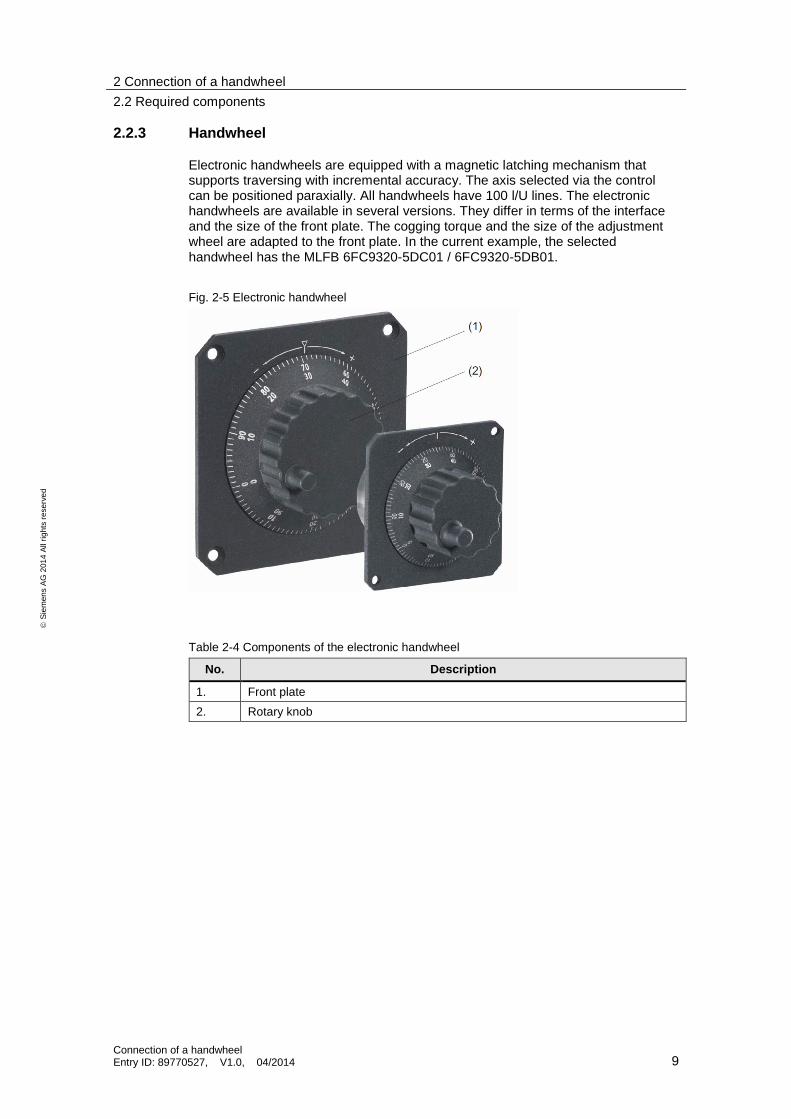
Electronic handwheels are equipped with a magnetic latching mechanism thatsupports traversing with incremental accuracy. The axis selected via the controlcan be positioned paraxially. All handwheels have 100 l/U lines. The electronichandwheels are available in several versions. They differ in terms of the interfaceand the size of the front plate. The cogging torque and the size of the adjustmentwheel are adapted to the front plate. In the current example, the selectedhandwheel has the MLFB 6FC9320-5DC01 / 6FC9320-5DB01.
Fig. 2-5 Electronic handwheel
Table 2-4 Components of the electronic handwheel
No. Description
1. Front plate2. Rotary knob

2 Connection of a handwheel2.3 Assembly of the components
Connection of a handwheelEntry ID: 89770527, V1.0, 04/2014 10
Siem
ens
AG20
14Al
lrig
hts
rese
rved
2.3 Assembly of the components
The three components (MCP, signal cable and handwheel) must be connected toone another. The X60/61 interface forms the connection between the MCP and thesignal cable by means of a plug-in connection system (Fig. 2-2).
Fig. 2-2 Connection between handwheel and MCP via the interface X60/61

2 Connection of a handwheel2.3 Assembly of the components
Connection of a handwheelEntry ID: 89770527, V1.0, 04/2014 11
Siem
ens
AG20
14Al
lrig
hts
rese
rved
The terminal on the back of the handwheel is the second interface. The eightelectric pin cable lugs must be connected at the six terminal connections of thehandwheel as per the following diagram (Tab. 2-5).After the handwheel is properly wired, it can immediately be put into operation. Thecontroller immediately localizes the handwheel, which dispenses with the need fora booting process for activating the function by switching the controller on and off.
Fig. 2-3 Signal cable and connecting terminal of the electronic handwheel
Table 2-5 Electrical connection between the handwheel and signal cable
No. Connection to handwheel terminal Connecting cable (color)
1. 5 V Brown and green2. 0 V Black and yellow3. /A Red4. A Orange5. /B Violet6. B Blue

3 Contact persons
Connection of a handwheelEntry ID: 89770527, V1.0, 04/2014 12
Siem
ens
AG20
14Al
lrig
hts
rese
rved
3 Contact personsSiemens AGIndustry SectorI DT MC MTS APC 2Frauenauracher Strasse 80D - 91056 Erlangen, GermanyE-mail: [email protected]
4 History
Table 4-1
Version Date Revision
V1.0 04/2014 First Edition