application engineering bulle t in ae8-1367
TRANSCRIPT

1© 2010 Emerson Climate TechnologiesPrinted in the U.S.A.
AE8-1367
Application Engineering
B U L L E T I N
CoreSense™ Protection for Copeland Discus® Compressors
AE8-1367 December 2010
Application Engineering
B U L L E T I N
Safety Safety Instructions .................................................................................................... 2 Safety Icon Explanation ............................................................................................ 2 Instructions Pertaining to Risk of Electrical Shock, Fire, or Injury to Persons ........................................................................................... 3 Safety Statements ..................................................................................................... 3Overview Nomenclature ............................................................................................................ 4 Protection .................................................................................................................. 4 Oil Protection ........................................................................................................ 4 Reverse Jog Feature ............................................................................................ 5 Motor Protection by Positive Temperature Coeffi cient (PTC) Sensors ................. 5 High Discharge Temperature Protection (Optional) .............................................. 5 Communication (Optional) ........................................................................................ 5 Remote Reset ...................................................................................................... 5 Fault History ......................................................................................................... 6 Application Usage ..................................................................................................... 6 Specifi cations ....................................................................................................... 6 Basic Wiring Diagrams ......................................................................................... 7 Variable Frequency Drives ................................................................................... 7 Copeland Digital™ Discus/ Conventional Unloader Compressors....................... 7 Copeland Demand Cooling .................................................................................. 7Installation Mounting ................................................................................................................... 7 Terminal Box and Current Sensing Toroid Connections ........................................... 7 Power Connections ................................................................................................... 7 Pilot Circuit Wiring ..................................................................................................... 7 Alarm Circuit Wiring (Optional) ................................................................................. 8 Stand-Alone Mode .................................................................................................... 8 Communication Network (Optional) .......................................................................... 8 Cable Routing/Daisy Chain Confi guration ............................................................ 8 Terminations ......................................................................................................... 9Commissioning DIP Switch Confi guration ......................................................................................... 10 Jumper Settings ....................................................................................................... 11 Network Setup in Emerson Retail Solutions' E2 ...................................................... 11 Enabling Discharge Temperature Lockout In The E2 .......................................... 19Operation Status Codes/LED Diagnostics ................................................................................ 22 Event Priority ............................................................................................................ 23 Performing a Remote Reset In the E2 Alarm Screen .............................................. 24 Emergency Bypass of a Damaged Motor Temperature (PTC) Protection Sensor ... 25Reference Drawings 2D Discus with CoreSense ...................................................................................... 26 3D Discus with CoreSense ...................................................................................... 27 4D Discus with CoreSense ...................................................................................... 28 6D Discus with CoreSense ...................................................................................... 29
Table of Contents
2© 2010 Emerson Climate TechnologiesPrinted in the U.S.A.
AE8-1367
Application Engineering
B U L L E T I N
Safety Instructions
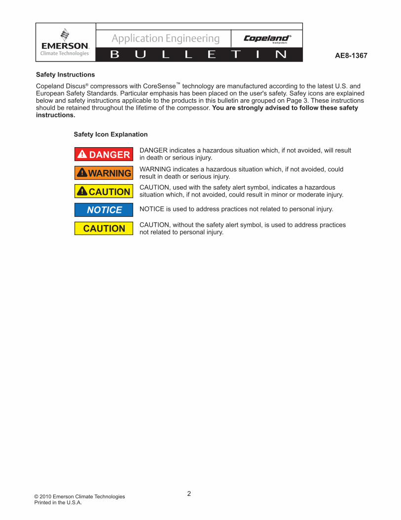
Copeland Discus® compressors with CoreSense™ technology are manufactured according to the latest U.S. and European Safety Standards. Particular emphasis has been placed on the user's safety. Safey icons are explained below and safety instructions applicable to the products in this bulletin are grouped on Page 3. These instructions should be retained throughout the lifetime of the compessor. You are strongly advised to follow these safety instructions.
Safety Icon Explanation
DANGER indicates a hazardous situation which, if not avoided, will result in death or serious injury.
WARNING indicates a hazardous situation which, if not avoided, could result in death or serious injury.
CAUTION, used with the safety alert symbol, indicates a hazardous situation which, if not avoided, could result in minor or moderate injury.
NOTICE is used to address practices not related to personal injury.
CAUTION, without the safety alert symbol, is used to address practices not related to personal injury.
DANGER
WARNING
CAUTION
NOTICE
CAUTION
3© 2010 Emerson Climate TechnologiesPrinted in the U.S.A.
AE8-1367
Application Engineering
B U L L E T I N
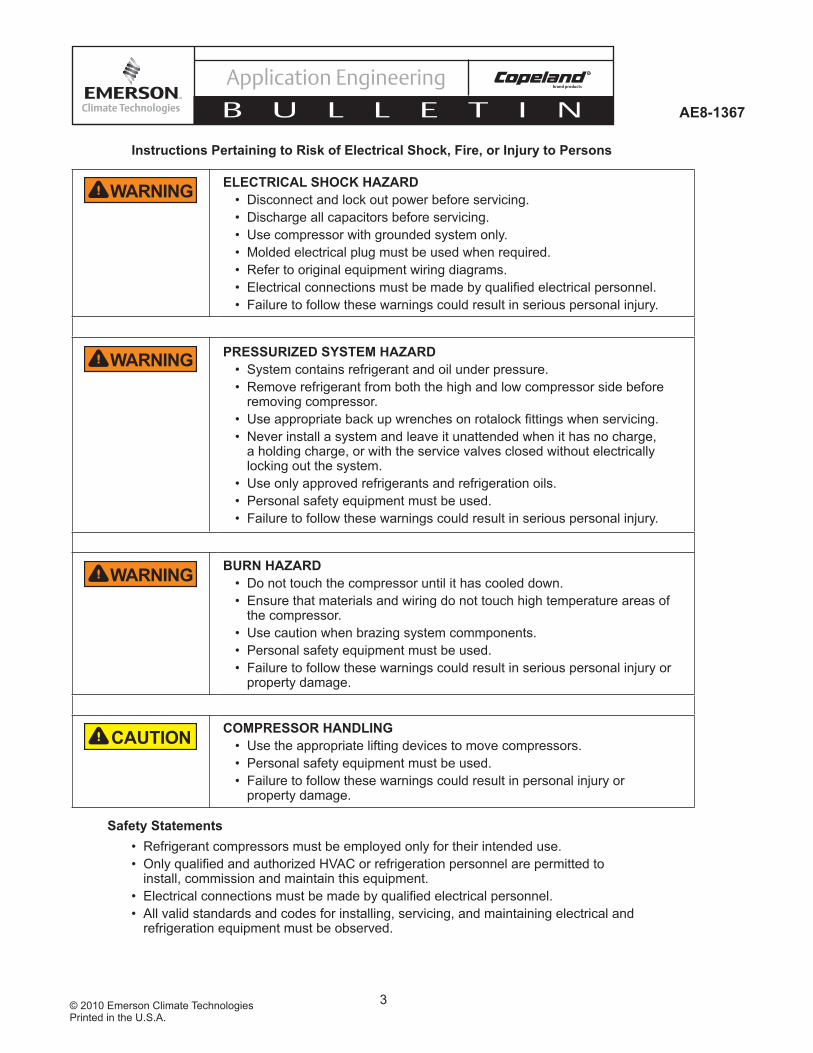
ELECTRICAL SHOCK HAZARD• Disconnect and lock out power before servicing. • Discharge all capacitors before servicing. • Use compressor with grounded system only. • Molded electrical plug must be used when required. • Refer to original equipment wiring diagrams. • • Failure to follow these warnings could result in serious personal injury.
PRESSURIZED SYSTEM HAZARD• System contains refrigerant and oil under pressure.• Remove refrigerant from both the high and low compressor side before
removing compressor. • • Never install a system and leave it unattended when it has no charge,
a holding charge, or with the service valves closed without electrically locking out the system.
• Use only approved refrigerants and refrigeration oils. • Personal safety equipment must be used. • Failure to follow these warnings could result in serious personal injury.
BURN HAZARD• Do not touch the compressor until it has cooled down. • Ensure that materials and wiring do not touch high temperature areas of
the compressor. • Use caution when brazing system commponents. • Personal safety equipment must be used. • Failure to follow these warnings could result in serious personal injury or
property damage.
COMPRESSOR HANDLING• Use the appropriate lifting devices to move compressors. • Personal safety equipment must be used. • Failure to follow these warnings could result in personal injury or
property damage.
Safety Statements• Refrigerant compressors must be employed only for their intended use. •
install, commission and maintain this equipment. • • All valid standards and codes for installing, servicing, and maintaining electrical and
refrigeration equipment must be observed.
Instructions Pertaining to Risk of Electrical Shock, Fire, or Injury to Persons
WARNING
WARNING
WARNING
CAUTION

4© 2010 Emerson Climate TechnologiesPrinted in the U.S.A.
AE8-1367
Application Engineering
B U L L E T I N
OVERVIEW The CoreSense™ Protection module (CPM) for Copeland Discus® compressors combines oil and motor protection into one module, as well as offers optional protection against high discharge temperature and communication compatibility with Modbus communication devices. Display LEDs clearly indicate the operational status of the compressor and whether or not there are any active compressor warnings, trips or lockouts active.
The CoreSense Protection product line is now available on Copeland® 2D, 3D, 4D and 6D Discus® compressors and integrates a number of important sensing and compressor protection functions. Some key components for the CoreSense Protection module are labeled in Figures 1 and 2.
NomenclatureFactory built Discus® compressors with an S/E (the last 3 digits in the model number) beginning with “C” are CoreSense Protection compressors. For example, 3DS3F46KL-TFD-C00.
PROTECTIONOil ProtectionCoreSense Protection replaces mechanical oil pressure sensing devices, the current Sentronic+™ as
well as older versions of the Copeland Sentronic® oil pressure control. Furthermore, it provides the added value of communication of low oil pressure warnings, oil pressure trips and oil pressure lockouts via LED codes and/or a supervisory rack controller, such as Emerson Retail Solutions’ E2. Insuffi cient oil pressure time for the compressor is stored and accumulated in the module memory. Once the total time accumulated for bad oil pressure (a reading less than 7-9 PSID) exceeds 120 seconds, the module will shut the compressor off and a “low oil pressure lockout” will be
Figure 1 – CoreSense Protection on Copeland Discus Compressors
CoreSense Protection Wiring Harness
CoreSense Protection Oil Pressure Sensor
CoreSense Protection Module (CPM)
Compressor Terminal Box
Red/Green LED Yellow LED
RESET Button
Figure 2 – Key Components on the CoreSense Protection Module

5© 2010 Emerson Climate TechnologiesPrinted in the U.S.A.
AE8-1367
Application Engineering
B U L L E T I N
reported. The compressor will turn back on once the reset has been activated either manually or remotely through the communication network, or when power has been cycled to the CoreSense Protection module.
Reverse Jog FeatureThe compressor will stop as long as the reset button on the bottom of the CoreSense Protection module is held in. This can be used for clearing liquid during a start-up. After the module re-boots (approximately 3 seconds) the compressor will run again. The reset button may be pushed as necessary to stop the compressor.
Motor Protection by Positive Temperature Coeffi cient (PTC) SensorsOn Copeland 4D and 6D Discus1 compressors, CoreSense Protection also provides protection for the motor replacing the Kriwan module INT369R. The CoreSense Protection module will communicate a motor protection trip when the resistance caused by increasing motor temperature rises above 13 kOhms. The compressor will restart once the resistance drops below 3.2 kOhms.
High Discharge Temperature Protection (Optional)
CAUTIONCompressor head temperatures can be very hot. Care must be taken to ensure that wiring or other materials which could be damaged by these temperatures do not come into contact with these potentially hot areas.
CoreSense Protection for Copeland Discus® compressors can also provide valuable discharge temperature protection. By installing the temperature probe into the head of the Discus compressor and connecting to the CPM, CoreSense will protect the compressor from high discharge temperature conditions. If the temperature sensor detects a head temperature greater than 310°F, the CoreSense will trip the compressor off until the temperature cools down to an acceptable level (about 267°F). A high discharge temperature lockout can also be enabled through the E2. Navigating the E2 setup screens (including enabling a high discharge temperature lockout) are discussed later in this bulletin.
For more information on the protection features, LED status codes, event priority and troubleshooting of CoreSense Protection refer to the section titled Status Codes/LED Diagnostics.
Communication (Optional)CoreSense Protection has an optional communication capability via a Modbus network connection. With communication enabled, CoreSense warnings, trips and lockouts can be displayed and recorded in a rack controller such as the E2.
Remote Reset
NOTICEService contractor and end user policies need to be considered when deciding whether or not to use the remote reset feature in the E2.
Figure 3 – E2 Alarm Table For CoreSense Protection1There are a select few 2D/3D Discus compressors that also use PTC Sensors. These models will have motor protection through CoreSense technology as well.Compressors with PTCs are indicated by an "S" in the second character of the electrical code, e.g. 4DH3R22ML-TSK-C00.

6© 2010 Emerson Climate TechnologiesPrinted in the U.S.A.
AE8-1367
Application Engineering
B U L L E T I N
CoreSense Protection for Copeland Discus is equipped with a remote reset capability, such that if a compressor is off in a lockout condition, the user can remotely restart the compressor through their E2 rack controller or compatible remote access software (e.g. UltraSite™). To set up remote reset via the E2, refer to section titled Performing a Remote Reset In the E2 Alarm Screen.
Fault HistoryCompressor faults are recorded within the CPM and if communicating with an E2 can also be stored in the E2 and CoreSense Alarm Tables for the past seven days. An example of the E2 Alarm Table is shown in Figure 3.
Application UsageSpecifi cationsOperating Temperature: Between -25°F and 150°F Voltage Requirements: 110 VAC or 220 VACInrush Current for Relay: 19A Steady load current for Relay : 3APower rating for the module: 3VAStorage temperature: Between -40°F and 185°F
Figure 4 - Basic Wiring Diagram
2
M
L
A
C
120v240v
CoreSense Terminal StripAlarmIndicator
ContactorCoil
L1 L2
HP LP T’Stat
Figure 5 – CoreSense Protection with Copeland Digital Compressor Controller
*
24COM24VACC1C2C3C4P1P2P3P4P5P6T1T2T3T4T5T6
V2
V1
U2
U1
M2
M1
L2
L1
24VACCONTROLLER
POWERCOMMON
+5VDCSIGNAL
1 – 5 VDCDemandSignal; From
System Controller
COMMONSIGNAL+5VDC
SUPPLY
Optional Suction
Pressure Transducer
Input
COMMON+5VDC
Optional0 – 5VDC Suction
Pressure Output
Discharge Temperature
Probe
A1
A2ALARM RELAY
OUTPUT
COMPRESSOR POWERWIRE T1
DIGITAL UNLOADERSOLENOID
2
M
L
A
120v240v
C
L1
L2
Control And Limit
Switches
CoreSense Terminal Strip
120 VAC240 VAC
For applications with Discus Digital and Copeland Demand Cooling a 5kOhm, 1W resistor should be installed at T1 and T2 on the Digital Compressor Controller, and the Demand Cooling Temperature Probe should be used. For more information on the Copeland Digital Compressor Controller refer to AE-1328.
*

7© 2010 Emerson Climate TechnologiesPrinted in the U.S.A.
AE8-1367
Application Engineering
B U L L E T I N
Figure 6 – CoreSense Protection with Copeland Demand Cooling
Control
CC
L1
L2
L2L1
120v240v
M
2
L
A
InjectionSolenoid
Temp.Sensor
Injector ControlSwitch
LM
AS
DemandCooling Module
CoreSenseModule Terminal Strip
* 120v or240v
* Note: The CoreSense Module Is Dual Rated for 120v / 240v. The Demand Cooling Module Must Be Matched To The Line Voltage
Basic System Wiring Diagram
WARNINGFusing and wire sizing must be done in accordance to all applicable electrical code standards.
Figure 4 shows the recommended basic system wiring for a Copeland Discus compressor with CoreSense Protection.
Variable Frequency Drives CoreSense Protection may be used with variable frequency drives. Refer to AE-1369 for more information on Copeland Discus with variable frequency drives.
Digital / Conventional Unloaded CompressorsCoreSense Protection may be used with Copeland Discus Digital™ as well as conventionally unloaded compressors. Refer to Figure 5 for recommended wiring with the Copeland Digital Compressor Controller.
Note! When applying Discus Digital with CoreSense Technology, the discharge temperature protection is done via the Digital Compressor Controller. Use the temperature probe provided with the Digital Compressor, NOT the optional temperature probe available for CoreSense. Discharge temperature information will not be communicated to the CoreSense Protection.
Demand CoolingCoreSense Protection is compatible with Copeland Demand Cooling®. However, the discharge temperature
protection is provided by the Demand Cooling module. Discharge temperature information will not be communicated to the CoreSense Protection module. For more information on Copeland Demand Cooling, refer to AE4-1287. Wiring of CoreSense Protection with Copeland Demand Cooling is shown in Figure 6.
INSTALLATIONMounting CoreSense Protection is designed and engineered for use in many refrigeration applications. Its environmental restrictions are not different than other Copeland Discus® compressors. As such, the compressor must be in an equipment room, rack house or roof enclosure to prevent direct precipitation on the compressor. The following clearance provisions must be considered when designing a system for use with a CoreSense Protection compressor:
• Removal of the cover of the module for access to dip-switches and the communication network connector
• Removal of the module for service reasons• Removal of terminal box lids for service reasons
Dimensional reference drawings for the 2D, 3D, 4D and 6D Discus with CoreSense Protection are found at the end of this document. Terminal Box and Current Sensing Toroid Connections
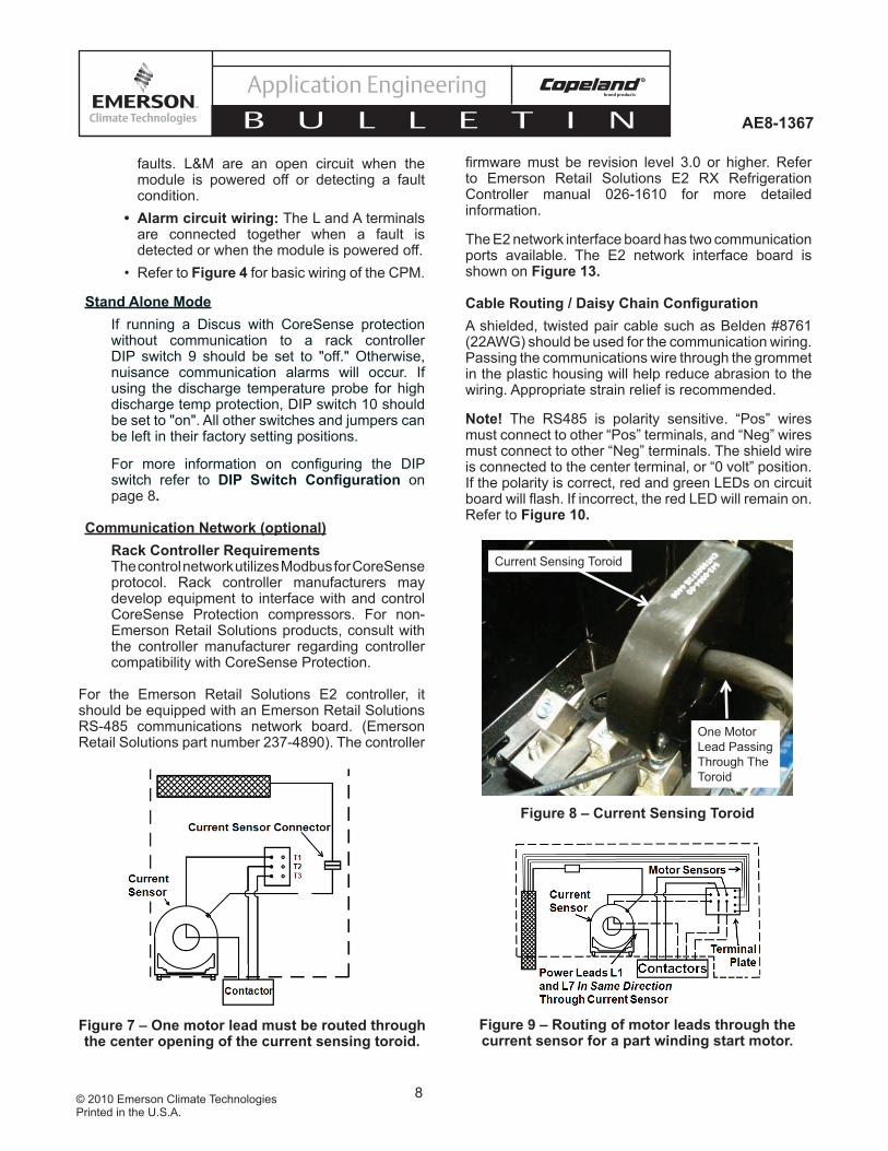
Terminal box and the current sensing toroid connections are installed at the factory. One of the motor power leads must be routed through the center opening in the toroid (refer to Figures 7 and 8). The current sensing toroid is used to determine if the compressor is running.
If using CoreSense Protection with a part winding start motor, power leads L1 and L7 both should be passed through the center opening in the same direction (see Figure 9) to provide accurate compressor proofi ng.
Power ConnectionsThe following power connections must be made by the original equipment manufacturer:
• Module power: 110/220 volts AC• Pilot circuit wiring: Pilot Circuit is wired
through the L and M terminal. The L and M terminals are connected together when CoreSense Protection is not detecting any
8© 2010 Emerson Climate TechnologiesPrinted in the U.S.A.
AE8-1367
Application Engineering
B U L L E T I N
faults. L&M are an open circuit when the module is powered off or detecting a fault condition.
• Alarm circuit wiring: The L and A terminals are connected together when a fault is detected or when the module is powered off.
• Refer to Figure 4 for basic wiring of the CPM.
Stand Alone ModeIf running a Discus with CoreSense protection without communication to a rack controller DIP switch 9 should be set to "off." Otherwise, nuisance communication alarms will occur. If using the discharge temperature probe for high discharge temp protection, DIP switch 10 should be set to "on". All other switches and jumpers can be left in their factory setting positions.
For more information on confi guring the DIP switch refer to DIP Switch Confi guration on page 8.
Communication Network (optional)Rack Controller RequirementsThe control network utilizes Modbus for CoreSense protocol. Rack controller manufacturers may develop equipment to interface with and control CoreSense Protection compressors. For non-Emerson Retail Solutions products, consult with the controller manufacturer regarding controller compatibility with CoreSense Protection.
For the Emerson Retail Solutions E2 controller, it should be equipped with an Emerson Retail Solutions RS-485 communications network board. (Emerson Retail Solutions part number 237-4890). The controller
fi rmware must be revision level 3.0 or higher. Refer to Emerson Retail Solutions E2 RX Refrigeration Controller manual 026-1610 for more detailed information.
The E2 network interface board has two communication ports available. The E2 network interface board is shown on Figure 13.
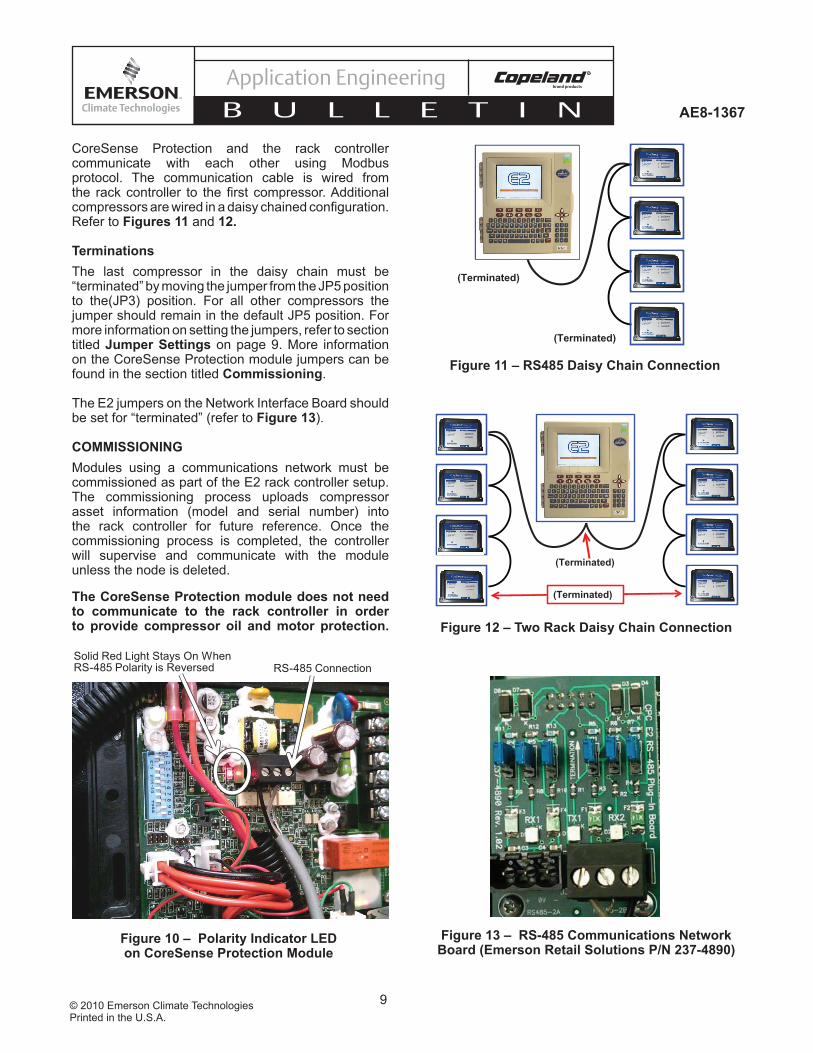
Cable Routing / Daisy Chain Confi gurationA shielded, twisted pair cable such as Belden #8761 (22AWG) should be used for the communication wiring.Passing the communications wire through the grommet in the plastic housing will help reduce abrasion to the wiring. Appropriate strain relief is recommended.
Note! The RS485 is polarity sensitive. “Pos” wires must connect to other “Pos” terminals, and “Neg” wires must connect to other “Neg” terminals. The shield wire is connected to the center terminal, or “0 volt” position. If the polarity is correct, red and green LEDs on circuit board will fl ash. If incorrect, the red LED will remain on. Refer to Figure 10.
Current Sensing Toroid
One Motor Lead Passing Through The Toroid
Figure 8 – Current Sensing Toroid
Figure 7 – One motor lead must be routed through the center opening of the current sensing toroid.
Figure 9 – Routing of motor leads through the current sensor for a part winding start motor.
9© 2010 Emerson Climate TechnologiesPrinted in the U.S.A.
AE8-1367
Application Engineering
B U L L E T I N
CoreSense Protection and the rack controller communicate with each other using Modbus protocol. The communication cable is wired from the rack controller to the fi rst compressor. Additional compressors are wired in a daisy chained confi guration. Refer to Figures 11 and 12.
TerminationsThe last compressor in the daisy chain must be “terminated” by moving the jumper from the JP5 position to the(JP3) position. For all other compressors the jumper should remain in the default JP5 position. For more information on setting the jumpers, refer to section titled Jumper Settings on page 9. More information on the CoreSense Protection module jumpers can be found in the section titled Commissioning.
The E2 jumpers on the Network Interface Board should be set for “terminated” (refer to Figure 13).
COMMISSIONINGModules using a communications network must be commissioned as part of the E2 rack controller setup. The commissioning process uploads compressor asset information (model and serial number) into the rack controller for future reference. Once the commissioning process is completed, the controller will supervise and communicate with the module unless the node is deleted.
The CoreSense Protection module does not need to communicate to the rack controller in order to provide compressor oil and motor protection.
Figure 13 – RS-485 Communications Network Board (Emerson Retail Solutions P/N 237-4890)
Solid Red Light Stays On When RS-485 Polarity is Reversed RS-485 Connection
Figure 10 – Polarity Indicator LED on CoreSense Protection Module
(Terminated)
(Terminated)
Figure 11 – RS485 Daisy Chain Connection
(Terminated)
(Terminated)
Figure 12 – Two Rack Daisy Chain Connection

10© 2010 Emerson Climate TechnologiesPrinted in the U.S.A.
AE8-1367
Application Engineering
B U L L E T I N
Using the communication process is optional, but provides for information fl ow to the controller for proofi ng, remote reset, asset information, and fault history and compressor status. Skip to section titled Stand Alone Mode if the communication feature will not be used.
The commissioning process begins by assigning a unique node address to each module. The address is established by the setting of a DIP switch in the module.
DIP Switch Confi gurationDIP switch selection for the Modbus address, baud rate, parity, and other operating conditions simplify service and start-up procedures. Table 1 lists the purpose for each switch. See Figure 14 for more information on DIP switch settings.
To access the DIP switch remove the four CoreSense Protection module cover screws. Then remove the cover.
Note! Press the reset button after changing any of the DIP settings for changes to take effect.
The following steps cover the DIP switch settings throughout the commissioning process for a multiple compressor system with communications to the E2:
1. Switches 1 through 6 are used for setting the address. Each CoreSense Protection device that is connected to a rack controller must have a unique node address (as determined by the DIP switch settings).
2. Switch 7 defi nes the communications baud rate for the CoreSense Protection module. If the switch is “off”, the baud rate is 19200. If the switch is “on” the baud rate is 9600. The baud rate for each of the CoreSense Discus™ devices should be set to match the rack controller. The default baud rate is 19200 (“off”) for the CoreSense Protection module. To determine the baud rate in the E2, follow these steps:• From the main menu select 7 (System
Confi guration)• Press 3 (System Information)• Press 1 (General Controller Info)• Access the Serial Communications Tab by
pressing CTRL + 3• Use the Page Down button or scroll down to
view the settings for COM43. Switch 8 defi nes the communication parity. The
default parity setting for the CoreSense Protection module is no parity. If the switch is set to “on” the module will communicate using even parity. The parity setting must match the parity setting of the rack controller.
4. Switch 9 is used to set the network mode (on) for the module. The default setting is stand alone mode (off). Network mode will generate a communications error if the rack controller fails
Figure 14 – Default CoreSense Protection DIP Switch Settings
"ON" (right)
"OFF" (left)
Node Addresses
DIP switch Number On Off
1 through 6 Modbus Module Address
7 Baud Rate = 9600
Baud Rate = 19,200
8 Even Parity No Parity9 Network Mode Stand Alone
10Enable
Discharge Temp Probe
No Probe
Table 1

11© 2010 Emerson Climate TechnologiesPrinted in the U.S.A.
AE8-1367
Application Engineering
B U L L E T I N
to communicate with the device. For standalone mode, no communications are expected so the communication error is blocked.
5. Switch 10 enables the optional discharge temperature probe. If the switch is set to “on’ the CoresSense Protection module will expect a discharge temperature probe. If the switch is set to “off” the CoreSense Protection module will not respond to the discharge temperature probe. The default setting is discharge temperature probe disabled (off).
Jumper SettingsThe communications jumper(JP4)should be set for ECT Modbus if connected to an E2 rack Controller (jumper pins 1-2). Use jumper pins 2-3 for other controllers. See Figure 15.
The last CoreSense Protection device in the daisy-chain should have a communication jumper in the “terminated” (JP3) position. All other modules should
have a jumper in the JP5 position. In addition, the E2 should have the communication jumpers on the communication card (typically COM4) in the “terminated” position.
Note! JP1 should not be removed.
Network Setup in Emerson Retail Solutions’ E2
NOTICEThe following section describes network set up with an E2 v3.0. Before beginning network setup, Emerson Climate Technologies recommends updating to the latest E2 fi rmware. For other controllers or newer versions of E2, contact your controller manufacturer representative.
Once the DIP switch settings have been verifi ed for each CoreSense module, you will need to establish communications with the new devices. Begin the network setup by following the steps on the next page.
Figure 15 Default jumper settings on the CoreSense Protection Module

12© 2010 Emerson Climate TechnologiesPrinted in the U.S.A.
AE8-1367
Application Engineering
B U L L E T I N
1. Press to Enter the Main Menu. Select 5. Configured Applications.
2. From the Configured Applications Menu Select 1. Suction Groups
Note! Before Making Any Changes In The E2 Setup, You Must Log In To The E2 By Pressing And Entering The Appropriate Username And Password
3. Select the Suction Group The CoreSense Devices Will Be Associated To. This Will Bring Up The Suction Group Status Screen.
4. Press F5 To Enter The Suction Group Setup Screen
13© 2010 Emerson Climate TechnologiesPrinted in the U.S.A.
AE8-1367
Application Engineering
B U L L E T I N
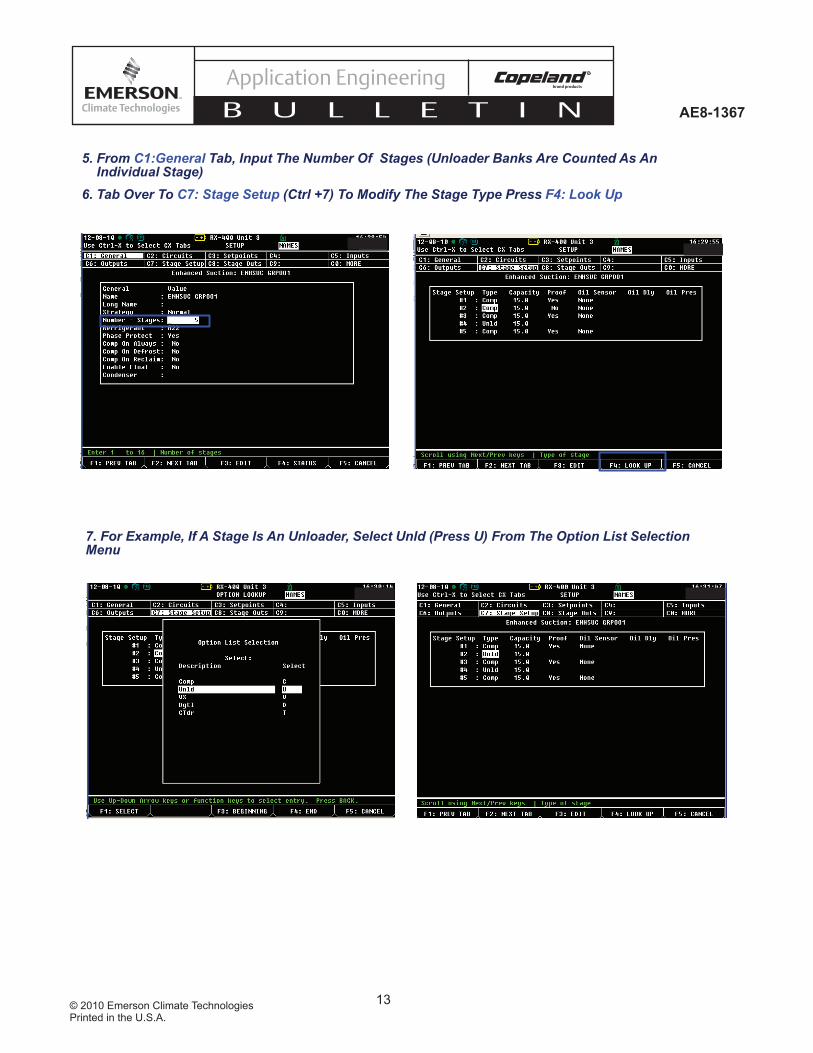
5. From C1:General Tab, Input The Number Of Stages (Unloader Banks Are Counted As An Individual Stage)
6. Tab Over To C7: Stage Setup (Ctrl +7) To Modify The Stage Type Press F4: Look Up
7. For Example, If A Stage Is An Unloader, Select Unld (Press U) From The Option List Selection Menu
14© 2010 Emerson Climate TechnologiesPrinted in the U.S.A.
AE8-1367
Application Engineering
B U L L E T I N
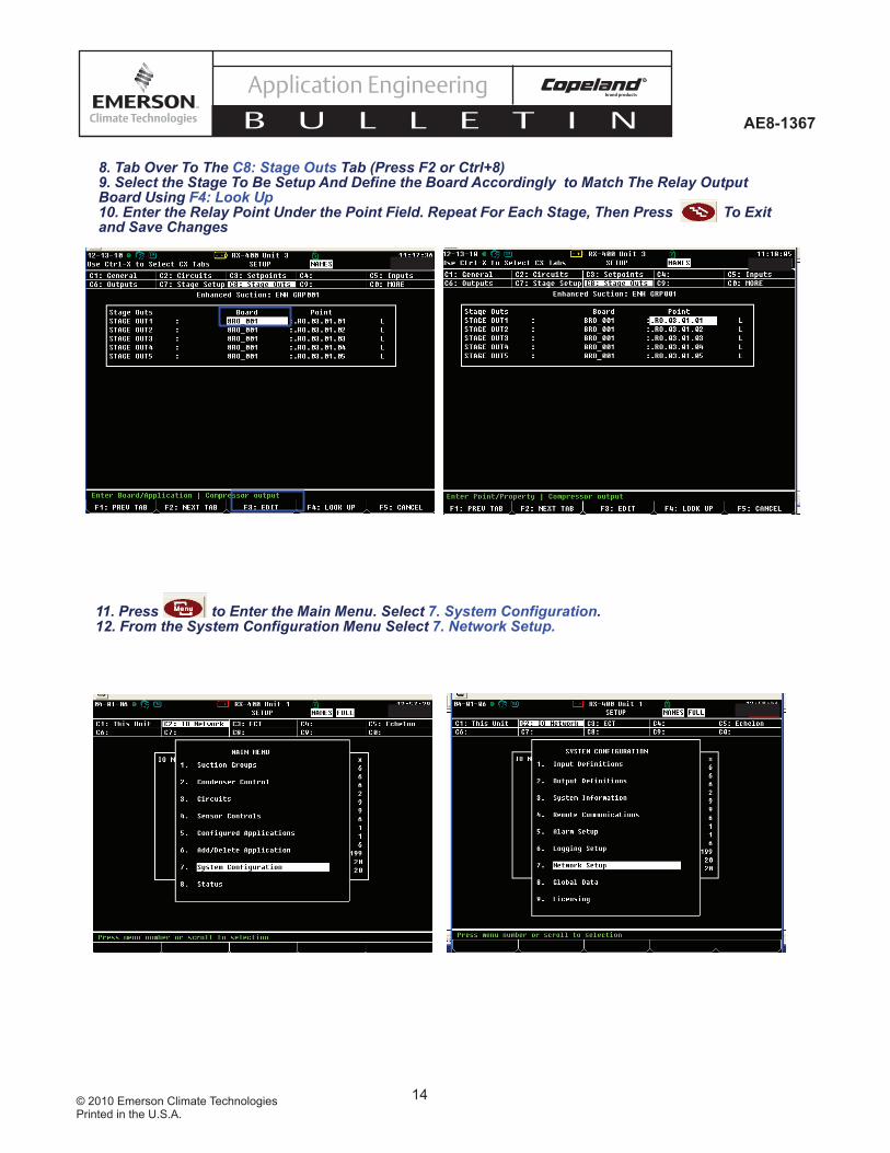
8. Tab Over To The C8: Stage Outs Tab (Press F2 or Ctrl+8) 9. Select the Stage To Be Setup And Define the Board Accordingly to Match The Relay Output Board Using F4: Look Up10. Enter the Relay Point Under the Point Field. Repeat For Each Stage, Then Press To Exit and Save Changes
11. Press to Enter the Main Menu. Select 7. System Configuration.12. From the System Configuration Menu Select 7. Network Setup.

15© 2010 Emerson Climate TechnologiesPrinted in the U.S.A.
AE8-1367
Application Engineering
B U L L E T I N
13. From the Network Setup Menu Select 2. Connected I/O Boards and Controllers
14. From the Setup Screen Go To The C3: ECT Tab (Press Ctrl + 3)
15. In Option #5, Enter The Number Of Discus Compressors Being Controlled By The E2. Press To Save Changes And Return To The Previous Screen.
16. From the Network Setup Menu Select 1. Network Summary
17. The Discus Devices Should Be Present On The Network. Select The Discus To Be Commissioned. Press F4: Commission

16© 2010 Emerson Climate TechnologiesPrinted in the U.S.A.
AE8-1367
Application Engineering
B U L L E T I N
18. From the Modbus Device Menu Select an Unused Space That Matches The DIP Switch Address Of The CoreSense Device And Press Enter.
19. Verify The Address Matches The Address Assigned By The CoreSense Module’s DIP Switch.
20. Press To Return To The Network Summary Screen. The Device Should Now Be “Online”. Repeat Steps 8-10 To Address The Remaining CoreSense Devices.
21. Once All The Devices Are Addressed, Press To Save Changes And Exit The Network Summary.
Once All CoreSense Devices Are Addressed The E2 Should Show Them All “Online”
17© 2010 Emerson Climate TechnologiesPrinted in the U.S.A.
AE8-1367
Application Engineering
B U L L E T I N
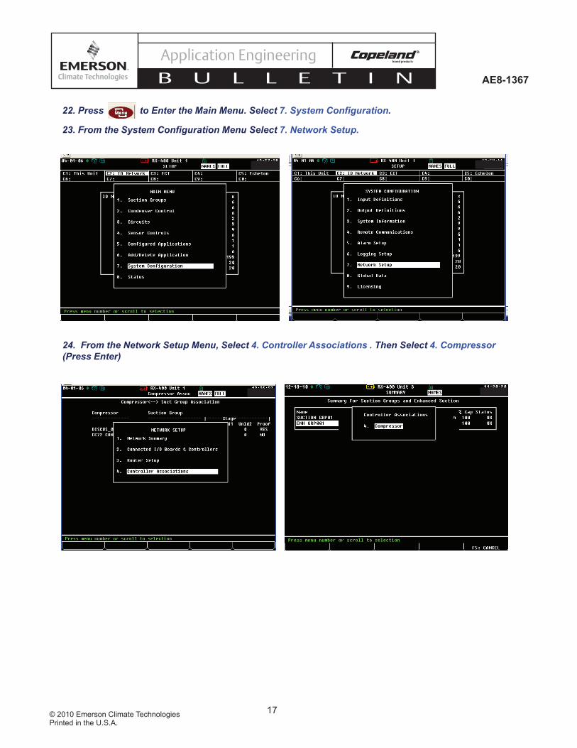
22. Press to Enter the Main Menu. Select 7. System Configuration.
23. From the System Configuration Menu Select 7. Network Setup.
24. From the Network Setup Menu, Select 4. Controller Associations . Then Select 4. Compressor (Press Enter)
18© 2010 Emerson Climate TechnologiesPrinted in the U.S.A.
AE8-1367
Application Engineering
B U L L E T I N
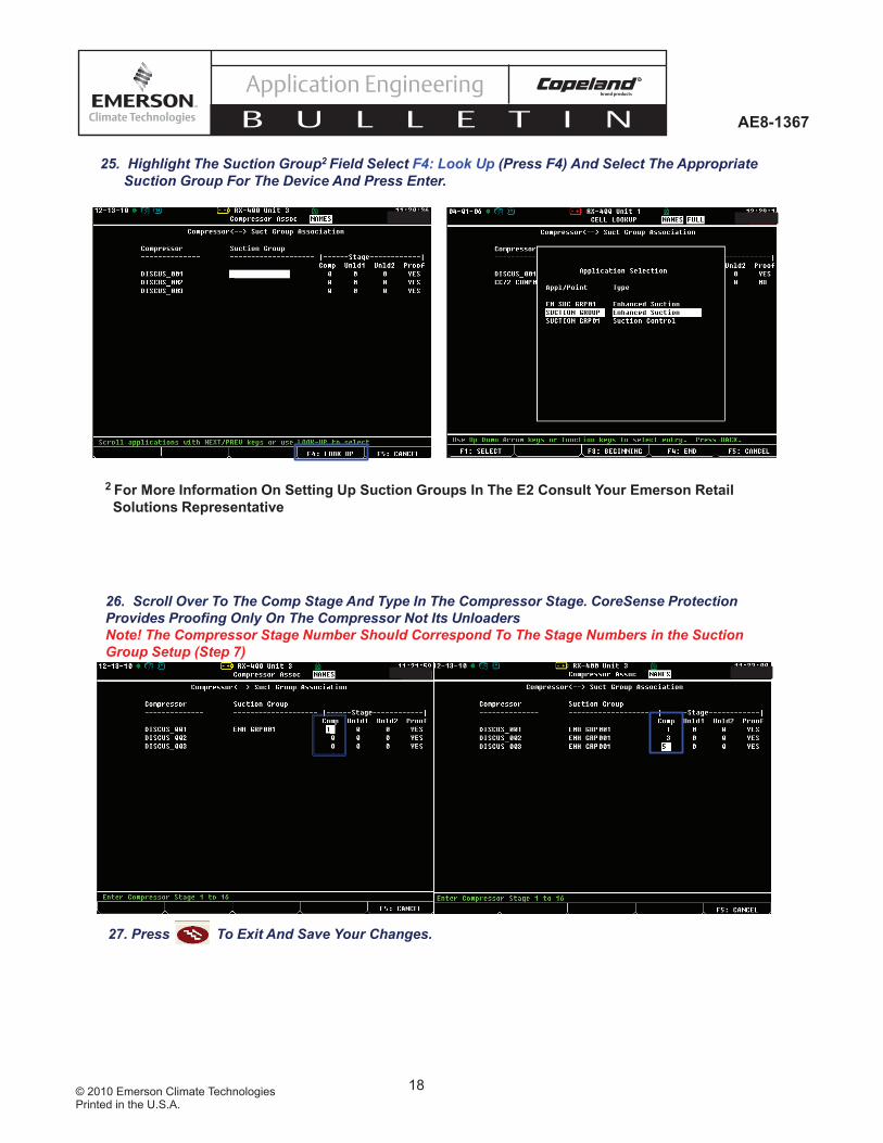
25. Highlight The Suction Group2 Field Select F4: Look Up (Press F4) And Select The Appropriate Suction Group For The Device And Press Enter.
2 For More Information On Setting Up Suction Groups In The E2 Consult Your Emerson Retail Solutions Representative
26. Scroll Over To The Comp Stage And Type In The Compressor Stage. CoreSense Protection Provides Proofing Only On The Compressor Not Its UnloadersNote! The Compressor Stage Number Should Correspond To The Stage Numbers in the Suction Group Setup (Step 7)
27. Press To Exit And Save Your Changes.

19© 2010 Emerson Climate TechnologiesPrinted in the U.S.A.
AE8-1367
Application Engineering
B U L L E T I N
Enabling Discharge Temperature Lockout in the E2Enabling Discharge Temperature Lockout in the E2The default setting for CoreSense using Discharge Temperature protection is only a trip alarm. When the head tem-The default setting for CoreSense using Discharge Temperature protection is only a trip alarm. When the head tem-perature of the compressor rises above 310°F, the compressor will shut off until the temperature falls below 267°F. perature of the compressor rises above 310°F, the compressor will shut off until the temperature falls below 267°F. If it is preferred to have the compressor shut off and stay off in a high discharge temperature condition, a discharge If it is preferred to have the compressor shut off and stay off in a high discharge temperature condition, a discharge temperature lockout can be enabled in the E2. The following steps discuss enabling a discharge temperature lock-temperature lockout can be enabled in the E2. The following steps discuss enabling a discharge temperature lock-out in the CoreSense device.out in the CoreSense device.
1. Press to Enter the Main Menu. Select 7. System Configuration.
2. From the System Configuration Menu Select 7. Network Setup
Note! Before Making Any Changes In The E2 Setup, You Must Log In To The E2 By Pressing And Entering The Appropriate Username And Password
20© 2010 Emerson Climate TechnologiesPrinted in the U.S.A.
AE8-1367
Application Engineering
B U L L E T I N
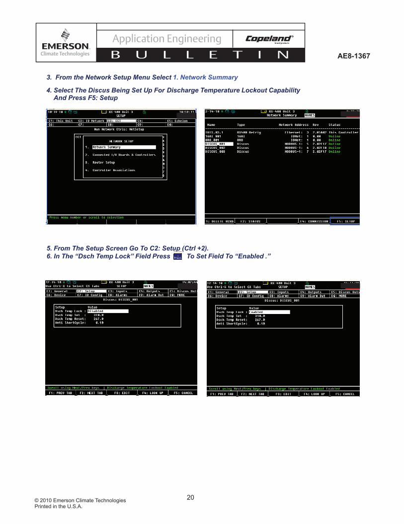
3. From the Network Setup Menu Select 1. Network Summary
4. Select The Discus Being Set Up For Discharge Temperature Lockout Capability And Press F5: Setup
5. From The Setup Screen Go To C2: Setup (Ctrl +2). 6. In The “Dsch Temp Lock” Field Press To Set Field To “Enabled .”
21© 2010 Emerson Climate TechnologiesPrinted in the U.S.A.
AE8-1367
Application Engineering
B U L L E T I N
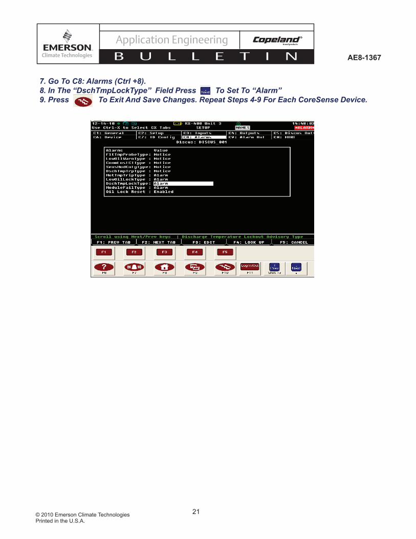
7. Go To C8: Alarms (Ctrl +8). 8. In The “DschTmpLockType” Field Press To Set To “Alarm”9. Press To Exit And Save Changes. Repeat Steps 4-9 For Each CoreSense Device.
22© 2010 Emerson Climate TechnologiesPrinted in the U.S.A.
AE8-1367
Application Engineering
B U L L E T I N
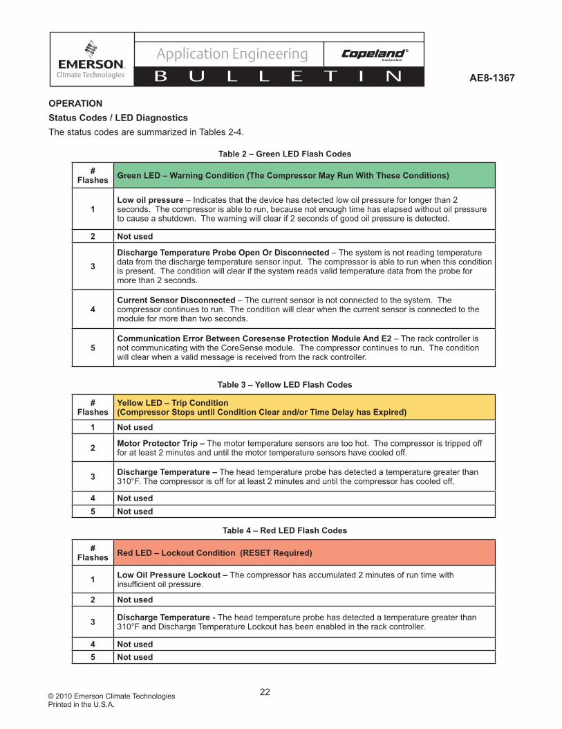
OPERATIONStatus Codes / LED DiagnosticsThe status codes are summarized in Tables 2-4.
# Flashes Green LED – Warning Condition (The Compressor May Run With These Conditions)
1Low oil pressure – Indicates that the device has detected low oil pressure for longer than 2 seconds. The compressor is able to run, because not enough time has elapsed without oil pressure to cause a shutdown. The warning will clear if 2 seconds of good oil pressure is detected.
2 Not used
3Discharge Temperature Probe Open Or Disconnected – The system is not reading temperature data from the discharge temperature sensor input. The compressor is able to run when this condition is present. The condition will clear if the system reads valid temperature data from the probe for more than 2 seconds.
4Current Sensor Disconnected – The current sensor is not connected to the system. The compressor continues to run. The condition will clear when the current sensor is connected to the module for more than two seconds.
5Communication Error Between Coresense Protection Module And E2 – The rack controller is not communicating with the CoreSense module. The compressor continues to run. The condition will clear when a valid message is received from the rack controller.
# Flashes
Yellow LED – Trip Condition (Compressor Stops until Condition Clear and/or Time Delay has Expired)
1 Not used
2 Motor Protector Trip – The motor temperature sensors are too hot. The compressor is tripped off for at least 2 minutes and until the motor temperature sensors have cooled off.
3 Discharge Temperature – The head temperature probe has detected a temperature greater than 310°F. The compressor is off for at least 2 minutes and until the compressor has cooled off.
4 Not used5 Not used
# Flashes Red LED – Lockout Condition (RESET Required)
1 Low Oil Pressure Lockout – The compressor has accumulated 2 minutes of run time with insufficient oil pressure.
2 Not used
3 Discharge Temperature - The head temperature probe has detected a temperature greater than 310°F and Discharge Temperature Lockout has been enabled in the rack controller.
4 Not used5 Not used
Table 2 – Green LED Flash Codes
Table 3 – Yellow LED Flash Codes
Table 4 – Red LED Flash Codes

23© 2010 Emerson Climate TechnologiesPrinted in the U.S.A.
AE8-1367
Application Engineering
B U L L E T I N
Priority Event E2 Alarm Display CPM LED
1 CoreSense Protection Module failure "Module Failure Lockout" Steady RED
2 Discharge Temperature Lockout "Discharge Temp Lockout" Flashing RED 3 Counts
3 Low Oil Pressure lockout "Low Oil Pressure Lockout" Flashing RED 1 Count
4 Motor Protector Trip "Motor Temp Trip" Flashing YELLOW 2 Counts
5 Discharge Temperature Trip "Discharge Temp Trip" Flashing YELLOW 3 Counts
6 Loss Of Communication Between CPM & E2 "No Communication" Flashing GREEN 5 Counts
7 E2 Confi g Mismatch “E2 confi g mismatch” Flashing GREEN 5 Counts
8 RESERVED FOR FUTURE USE
9 Low Oil Pressure Warning "Low Oil Pressure" Flashing Green 1 Count
10 RESERVED FOR FUTURE USE
11 Open Thermistor "Fault Temp Probe" Flashing GREEN 3 Counts
12 Normal Run "Normal Running" Solid GREEN
13 Normal Off "Normal Off" Solid GREEN
Table 5 – Event Priority for CoreSense Protection Faults
Event PriorityIf the module sees more than one event at a time it will choose to display the highest priority event on the LEDs and on the E2. The alarm priorities are defi ned in Table 5 where “1” is the highest priority.

24© 2010 Emerson Climate TechnologiesPrinted in the U.S.A.
AE8-1367
Application Engineering
B U L L E T I N
Performing a Remote Reset in the E2 Alarm Screen
NOTICEService contractor and end user policies need to be considered when deciding whether or not to use the remote reset feature in the E2.The following section discusses the procedures for reseting a CoreSense alarm remotely from the E2. Any alarm in the E2 can be reset provided the condition that caused the alarm has been resolved and established time delays have been satisfi ed.
1. Press to Enter the Alarm Screen of The E2.2. Select The Alarm To Be Reset and Press F2:Alarm Rst. Press A To Reset The Advisory.
3. The Alarm Table Will Now Show That The Alarm Has Been Reset.

25© 2010 Emerson Climate TechnologiesPrinted in the U.S.A.
AE8-1367
Application Engineering
B U L L E T I N
Emergency Bypass of a Damaged Motor Temperature (PTC) Protection Sensor
CAUTIONAt no time should more than one motor sensor be bypassed. In the unlikely event that one sensor may be damaged and have an open or shorted circuit, CoreSense Protection will prevent compressor operation (and display a motor protection alarm) even though the motor may be in perfect condition. If such a situation should be encountered in the fi eld, an emergency means of operating the compressor can be used until such time as a replacement can be made. Connect a properly sized resistor between the CoreSense
Protection motor leads and the common sensor terminal in the compressor terminal box. This indicates to the control module an acceptable resistance in the damaged sensor circuit, and compressor operation can be restored (see Figure 16). If an internal sensor is shorted, the wire from the sensor to the sensor terminal should be disconnected when installing the resistor. In effect, the compressor will continue operation with two leg protection rather than three leg protection. While this obviously does not provide the same high degree of protection, it does provide a means of continuing compressor operation with a degree of safety.
The specifi cations for the emergency resistor are asfollows:
One watt (or larger), 2200 ohm ±10%resistor
C
S1
S2
S3
Open Sensor
2200 OHM Resistor
Internal Motor Sensor Leads
Harness With Motor Sensor
Leads
O O O Black
Terminal Strip
Figure 16Emergency Bypass of damaged motor temperature (PTC) protection sensor

26© 2010 Emerson Climate TechnologiesPrinted in the U.S.A.
AE8-1367
Application Engineering
B U L L E T I N
REFERENCE DRAWINGS
Figure 17 – Dimensional Drawing for 2D Discus With CoreSense Protection
27© 2010 Emerson Climate TechnologiesPrinted in the U.S.A.
AE8-1367
Application Engineering
B U L L E T I N
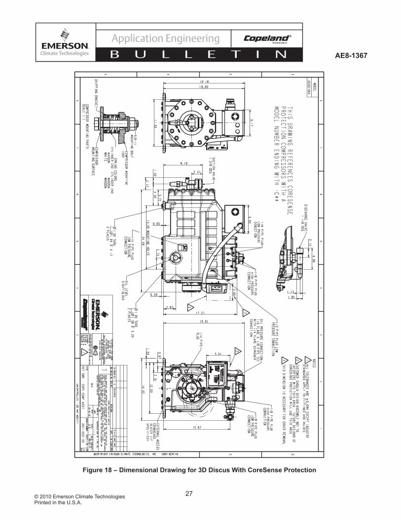
Figure 18 – Dimensional Drawing for 3D Discus With CoreSense Protection

28© 2010 Emerson Climate TechnologiesPrinted in the U.S.A.
AE8-1367
Application Engineering
B U L L E T I N
Figure 19 – Dimensional Drawing for 4D Discus With CoreSense Protection
29© 2010 Emerson Climate TechnologiesPrinted in the U.S.A.
AE8-1367
Application Engineering
B U L L E T I N
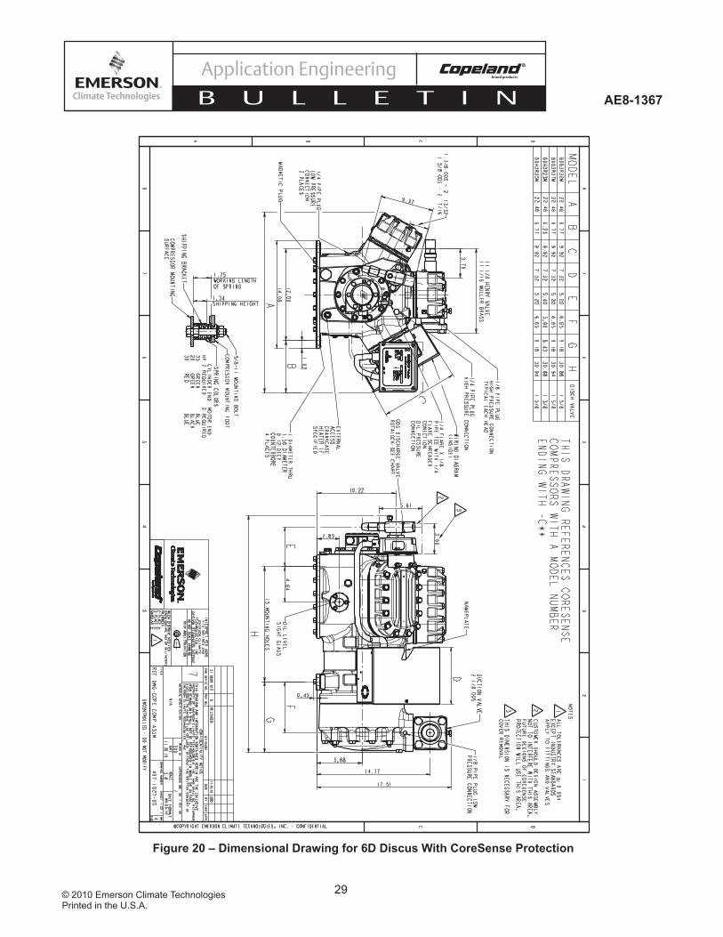
Figure 20 – Dimensional Drawing for 6D Discus With CoreSense Protection