application example 09/2016 pcs 7 in the mining … · pcs 7 in the mining industry (demo project)...
TRANSCRIPT

https://support.industry.siemens.com/cs/ww/en/view/81723640
Application example 09/2016
PCS 7 in the mining industry (demo project) SIMATIC PCS 7, Minerals Automation Standard / CEMAT

Warranty and liability
PCS 7 Demo project (mining) Entry ID: 81723640, V2.0, 09/2016 2
S
iem
en
s A
G 2
01
6 A
ll ri
gh
ts r
ese
rve
d
Warranty and liability
Note The Application Examples are not binding and do not claim to be complete regarding configuration, equipping and any eventuality. The Application Examples do not represent customer-specific solutions. They are only intended to provide support for typical applications. You are responsible for proper operation of the described products. These application examples do not relieve you of the responsibility to use safe practices in application, installation, operation and maintenance. When using these Application Examples, you recognize that we cannot be made liable for any damage/claims beyond the liability clause described. We reserve the right to make changes to these Application Examples at any time without prior notice. If there are any deviations between the recommendations provided in these Application Examples and other Siemens publications – e.g. Catalogs – the contents of the other documents have priority.
We do not accept any liability for the information contained in this document. Any claims against us – based on whatever legal reason – resulting from the use of the examples, information, programs, engineering and performance data etc., described in this Application Example shall be excluded. Such an exclusion shall not apply in the case of mandatory liability, e.g. under the German Product Liability Act ("Produkthaftungsgesetz"), in case of intent, gross negligence, or injury of life, body or health, guarantee for the quality of a product, fraudulent concealment of a deficiency or breach of a condition which goes to the root of the contract ("wesentliche Vertragspflichten"). The damages for a breach of a substantial contractual obligation are, however, limited to the foreseeable damage, typical for the type of contract, except in the event of intent or gross negligence or injury to life, body or health. The above provisions do not imply a change of the burden of proof to your detriment. Any form of duplication or distribution of these Application Examples or excerpts hereof is prohibited without the expressed consent of the Siemens AG.
Security infor-
mation
Siemens provides products and solutions with industrial security functions that support the secure operation of plants, systems, machines, and networks.
To protect plants, systems, machines, and networks against cyber threats, it is necessary to implement – and to continuously maintain – a holistic, state-of-the-art industrial security concept. Siemens’ products and solutions form only one element of such a concept.
Customers are responsible for preventing unauthorized access to their plants, systems, machines, and networks Systems, machines, and components should only be connected to the enterprise network or the Internet if necessary and only to the extent necessary, and with appropriate protective measures in place (e.g., use of firewalls and network segmentation).
In addition, you should pay attention to Siemens’ recommendations on appropriate protective measures For more information about industrial security, go to http://www.siemens.com/industrialsecurity.
The products and solutions of Siemens are being constantly developed further in order to render them even more secure. Siemens strongly recommends applying product updates as soon as they are available and to always use the latest product versions. The use of obsolete versions or versions that are no longer supported can increase the risk of cyber threats.
In order to be informed about product updates at all times, be sure to subscribe to the Siemens Industrial Security RSS Feed on http://www.siemens.com/industrialsecurity.

Table of contents
PCS 7 Demo project (mining) Entry ID: 81723640, V2.0, 09/2016 3
S
iem
en
s A
G 2
01
6 A
ll ri
gh
ts r
ese
rve
d
Table of contents Warranty and liability ................................................................................................... 2
1 Overview ............................................................................................................. 5
2 Minerals Automation Standard / CEMAT ......................................................... 6
2.1 The MinAS philosophy ......................................................................... 6 2.2 The advantages of MinAS .................................................................... 7 2.3 The MinAS operating methodology ...................................................... 8 2.4 Main features of the MinAS .................................................................. 9 2.5 MinAS blocks ...................................................................................... 10 2.5.1 Drive functions .................................................................................... 10 2.5.2 Control/monitoring .............................................................................. 11 2.5.3 Scalable production control ................................................................ 11
3 Mining demo project ........................................................................................ 13
3.1 General overview ............................................................................... 13 3.2 Process pictures ................................................................................. 15 3.3 "Crushing" system area ...................................................................... 18 3.3.1 Primary crusher .................................................................................. 19 3.3.2 Operator controls for groups, routes and maintenance ..................... 20 3.3.3 Conveyor belts ................................................................................... 21 3.3.4 Stockpile ............................................................................................. 21 3.4 Operator controls ................................................................................ 22 3.4.1 Faceplates .......................................................................................... 22 3.4.2 Object browser ................................................................................... 23 3.4.3 Integrated MinAS maintenance .......................................................... 24 3.4.4 Integrated MinAS trend ...................................................................... 24
4 Installation and commissioning of the demo project .................................. 25
4.1 Installing the MinAS ............................................................................ 25 4.2 Installing the demo project ................................................................. 26 4.3 Loading the AS program .................................................................... 26 4.4 Adapting the computer name ............................................................. 27 4.5 Customizing the OS project................................................................ 28 4.6 Launching the OS runtime.................................................................. 29 4.7 Initial state of the system .................................................................... 30
5 Operating the demo project ............................................................................ 34
5.1 Establishing the plant state using the object browser ........................ 34 5.2 Performing error diagnostics using "Status call" and the object
list ....................................................................................................... 39 5.3 Starting and stopping system areas (groups) .................................... 43 5.4 Faults in groups being started or already in operation ....................... 49 5.5 Integrated MinAS trend configuration ................................................. 53 5.6 Performing system maintenance using the "Maintenance list" .......... 55 5.7 MinAS alarm view with filter functions ................................................ 58 5.8 MinAS recipe management ................................................................ 60
6 Further information ......................................................................................... 82
6.1 Application notes ................................................................................ 82 6.1.1 Process simulation ............................................................................. 82 6.1.2 Changing the operating mode ............................................................ 83 6.1.3 Storing messages on objects ............................................................. 84 6.2 Tips and tricks .................................................................................... 84
7 References ....................................................................................................... 86

Table of contents
PCS 7 Demo project (mining) Entry ID: 81723640, V2.0, 09/2016 4
S
iem
en
s A
G 2
01
6 A
ll ri
gh
ts r
ese
rve
d
8 History............................................................................................................... 86

1 Overview
PCS 7 Demo project (mining) Entry ID: 81723640, V2.0, 09/2016 5
S
iem
en
s A
G 2
01
6 A
ll ri
gh
ts r
ese
rve
d
1 Overview
Application objective
This document provides you with an overview of the functional scope of the Minerals Automation Standard (MinAS), as well as a description for commissioning and functional properties of the demo project.
Core contents of the application
The following key aspects are covered in this application:
Minerals Automation Standard / CEMAT
Installation and commissioning of the demo project
Operation of the demo project based on the example of typical operating scenarios
Validity
The software requirements for running the demo project are as follows:
SIMATIC PCS 7 V8.2 with a valid license or time-limited trial license
Minerals Automation Standard / CEMAT V8.2 with a valid license or time-limited demo mode
Note You can find information about the product at: Minerals Automation Standard / CEMAT
Contact: [email protected]

2 Minerals Automation Standard / CEMAT
2.1 The MinAS philosophy
PCS 7 Demo project (mining) Entry ID: 81723640, V2.0, 09/2016 6
S
iem
en
s A
G 2
01
6 A
ll ri
gh
ts r
ese
rve
d
2 Minerals Automation Standard / CEMAT The Siemens Industry Automation division developed the Minerals Automation Standard / CEMAT V8.2 to meet the special requirements of the mining industry.
This standard uses the SIMATIC PCS 7 process control system, with its open, flexible and scalable system architecture, as a system platform that is expanded to include specific automation functions for mining applications.
The Minerals Automation Standard / CEMAT V8.2 (hereinafter abbreviated as "MinAS") is a product for use in the mining and cement industry sectors.
2.1 The MinAS philosophy
MinAS is more than just a library containing a few specific modules for the mining industry. It also represents a complete philosophy:
How are devices such as conveyor belts, crushers and grinders, or even the entire process configured?
How are processes in the mining industry operated?
How can diagnostics be performed quickly and simply in order to keep unplanned plant downtime at a minimum in case of error?
As an integrated solution, the Minerals Automation Standard focuses on:
Efficient engineering and quality
Improved operation and monitoring

2 Minerals Automation Standard / CEMAT
2.2 The advantages of MinAS
PCS 7 Demo project (mining) Entry ID: 81723640, V2.0, 09/2016 7
S
iem
en
s A
G 2
01
6 A
ll ri
gh
ts r
ese
rve
d
2.2 The advantages of MinAS
Configuration
The plant engineer can benefit from many advantages during process configuration:
A tested and well-documented library of software modules for functions in the mining industry
Technology-oriented configuration to achieve the highest software quality, even without programming knowledge
Standard interface between the software modules to minimize faults
Integrated simulation functions for engineering and factory acceptance tests (FAT)
Bulk data processing
Operation
MinAS enables users to handle the system simply and intuitively thanks to:
Easy-to-understand symbols
Starting and stopping of entire process groups with a simple mouse click
Easy route selection
Efficient fault diagnostics

2 Minerals Automation Standard / CEMAT
2.3 The MinAS operating methodology
PCS 7 Demo project (mining) Entry ID: 81723640, V2.0, 09/2016 8
S
iem
en
s A
G 2
01
6 A
ll ri
gh
ts r
ese
rve
d
2.3 The MinAS operating methodology
Among other things, the Minerals Automation Standard operating philosophy is also based on different operating modes:
"Automatic"
"Manual"
"Local"
"Out of service"
Advantages for operations management can be seen, for instance, in typical applications such as system startup, troubleshooting (fault avoidance), maintenance and the exclusion of devices.
The standardized and proven operating concepts result in reliable operation, reinforced by the opportunity for standardized training.
Automatic mode
During normal operation, all drives in a technological system area are started and stopped in "Automatic mode." The start or stop command is then triggered by the start/stop sequence or by the configured process conditions.
Manual mode
In "Manual mode", the drives can be started and stopped individually at the operating station. The "Manual mode" can be specifically activated or deactivated for each individual drive or for groups.
Local mode
In this operating mode, interlocks are only active to a limited extent. The application areas for this operating mode are: commissioning, tests and maintenance work.
Out of service (maintenance)
The "Out of service" mode prevents the drive from starting and disables all control recipe phases by locking the control output. It also disables all messages. This operating mode is intended to be used with field devices that are defective or undergoing maintenance work.

2 Minerals Automation Standard / CEMAT
2.4 Main features of the MinAS
PCS 7 Demo project (mining) Entry ID: 81723640, V2.0, 09/2016 9
S
iem
en
s A
G 2
01
6 A
ll ri
gh
ts r
ese
rve
d
2.4 Main features of the MinAS
MinAS provides an extensive collection of preconfigured, tested and well documented mining-specific library elements in order to offer support in various different areas of application in the minerals industry (mining and cement). To do this, it uses PCS 7 standard functions such as CFC configuration. For each function block in the library, there is a block icon and corresponding faceplate with a consistent look and feel. The icon and faceplate are automatically generated for the graphical user interface and only arranged at the process screen in combination with statistical graphic elements. These library elements and templates reduce engineering time and improve engineering quality.
The essential functions are briefly described below:
Group control
Group elements enable the representation of a system area's operating state and provide detailed error diagnostics for all related objects.
All drives, displays and measured value of a system area are connected by a group element. This group provides summarized notes about faults and alarms and interrupts or prevents the starting procedure in case of error.
Global object browser
The object browser provides a status overview of the objects present in the system. Filter functions make it possible to search by operating mode, stored notes, maintenance state or bypassed interlocks.
Object list
The object list for a group shows the status of all related drives, measured values and process signals. In addition, drives can also display measured values and process signals assigned to them.
Information view
Additional information (links, documents, drawings, videos) can be linked to each object. Information can be added during operation.
Integrated MinAS trend
Simple configuration of a trend display by selecting analog values at the process screen during operation. The trend display can be saved and linked to a process area.

2 Minerals Automation Standard / CEMAT
2.5 MinAS blocks
PCS 7 Demo project (mining) Entry ID: 81723640, V2.0, 09/2016 10
S
iem
en
s A
G 2
01
6 A
ll ri
gh
ts r
ese
rve
d
Integrated MinAS maintenance
For drives and valves, additional information about maintenance and availability can be configured. A maintenance view gives an overview of operating hours, starts, stops with faults, and downtime.
Diagnostics view
List of all relevant block inputs and outputs with the corresponding status. There is also the option to change some of the block parameters directly in the diagnostics view.
MinAS alarm view
Up to 10 customized filters can be created for process messages. Filter types include: system area, measuring point, message type, message text, date, ...
In addition, "Smart" filters make it possible to display alarms for active objects only.
2.5 MinAS blocks
A detailed and complete description of the functions can be found in the product description. All of the blocks from the SIMATIC PCS 7 standard libraries can also be used.
The blocks relevant for this demonstration are listed below.
2.5.1 Drive functions
C_DRV_1D
The C_DRV_1D block is used to control drives with one direction.
C_DRV_2D
The C_DRV_2D block is used to control drives with two directions.
C_VALVE
The C_VALVE block is used to control valves.
C_SIMOS
The C_SIMOS SIMCODE adapter block connects CEMAT drive blocks with SIMCODE.
C_ANNUN8
At the C_ANNUN8 block, up to 7 binary process signals can be displayed. If one of the process signals experiences a malfunction, then a fault or alarm message is generated.
C_ANNUNC
At the C_ANNUNC block, one binary process signal can be displayed. If the process signal experiences a malfunction, then a fault or alarm message is generated.

2 Minerals Automation Standard / CEMAT
2.5 MinAS blocks
PCS 7 Demo project (mining) Entry ID: 81723640, V2.0, 09/2016 11
S
iem
en
s A
G 2
01
6 A
ll ri
gh
ts r
ese
rve
d
C_MEASUR
The C_MEASUR block can be used to read analog process data and monitor up to 8 limit values. It is possible to configure 4 of the limit values for the generation of fault/alarm messages. The other 4 limits are switching limits and do not generate any alarms.
C_PROFB
The C_PROFB block can monitor binary or analog process feedback signals from a drive, such as rotational speed or pressures.
If there is a fault in the process feedback, the drive will be stopped via a protective interlock.
2.5.2 Control/monitoring
C_GROUP
The C_GROUP block is a higher-level module used to switch technologically related devices on and off in automatic mode.
The group block allows the visualization of operating states for a plant unit in the form of a status display and detailed fault diagnostics (status call).
C_ROUTE
The C_ROUTE block is a module for selecting transport routes within a group.
C_SELECT
The C_SELECT block can be used for every type of selection function. In contrast to the C_ROUTE block, it does not offer fault diagnostics.
2.5.3 Scalable production control
C_P_MAT
The C_P_MAT block is an element for CEMAT MinAS Scalable Production Control. This block can manage up to 24 storage locations for products or raw materials. The operator can assign materials to the storage locations at execution time.
C_P_MGR
The C_P_MGR block is the central element of the CEMAT MinAS Scalable Production Control. This block can manage 25 recipes plus an additional recipe – so called "Final recipe" (FR, recipe 99).
C_PD_AR
The C_PD_AR (Absolute, REAL) block is the data distributer of the CEMAT MinAS Scalable Production Control for the C_PM_AR recipe module. The block has the setpoint outputs for the recipe module of the active recipe.
C_PD_RTR
The block C_PD_RTR (Relative, Totalizing, REAL) is the data distributor of the CEMAT MinAS Scalable Production Control for the recipe module C_PM_RTR. The block has setpoint outputs for the recipe module of the active recipe.

2 Minerals Automation Standard / CEMAT
2.5 MinAS blocks
PCS 7 Demo project (mining) Entry ID: 81723640, V2.0, 09/2016 12
S
iem
en
s A
G 2
01
6 A
ll ri
gh
ts r
ese
rve
d
C_PM_AR
The block C_PM_AR (Absolute, REAL) is a recipe module of the CEMAT MinAS Scalable Production Control. The module has up to predefined 8 setpoints as absolute values (for instance, as revolutions per minute for a speed setpoint). All values are of the REAL type.
C_PM_RTR
The block C_PM_RTR (Relative, Totalizing, REAL) is a recipe module for the CEMAT MinAS Scalable Production Control. The module has up to 8 setpoints of a reference size (RV) given in percent. The first setpoint cannot be changed by the operator and is always the difference between 100% and the sum of setpoints 2 to 7. All values are of the REAL type.

3 Mining demo project
3.1 General overview
PCS 7 Demo project (mining) Entry ID: 81723640, V2.0, 09/2016 13
S
iem
en
s A
G 2
01
6 A
ll ri
gh
ts r
ese
rve
d
3 Mining demo project
3.1 General overview
The mining demo project illustrates the different process stages of a typical mining system and its plant hierarchy in the form of an overview.
In the process, the basic functionality and operation of MinAS are explained using the example of the "Primary crushing" plant unit.
The MinAS demo project is divided into an AS section and an OS section.
AS section
In the "Primary crushing" plant unit of the AS program, the logic is configured for a crusher, conveyor belts and dust collectors. The program contains blocks for the acquisition of analog and digital data, blocks for controlling motors and valves, and the blocks for route and group functions. If no process connection is available, the signals and process data can be simulated with the help of a special test block.

3 Mining demo project
3.1 General overview
PCS 7 Demo project (mining) Entry ID: 81723640, V2.0, 09/2016 14
S
iem
en
s A
G 2
01
6 A
ll ri
gh
ts r
ese
rve
d
OS section
The demo project contains multiple process screens that are intended to clarify the project using the example of a processing plant (e.g., for copper). The function of a crusher, including the removal of the raw material by conveyor belts is visualized in the "Crushing" system area, and the basic elements of the recipe for a cement grinding with SPC are realized by way of example.
These system areas are configured for the demonstration of MinAS.
The remaining screens are static and do not have an individual function.

3 Mining demo project
3.2 Process pictures
PCS 7 Demo project (mining) Entry ID: 81723640, V2.0, 09/2016 15
S
iem
en
s A
G 2
01
6 A
ll ri
gh
ts r
ese
rve
d
3.2 Process pictures
Using the plant hierarchy, you can navigate between the overview, crushing, grinding, rougher, cleaner, tailings and SPC example screens in the OS runtime. These screens are briefly described in the following table:
Description Screen
Process pictures
Here, you are given an overview of the system and can switch directly to the desired plant unit using the buttons.
Crushing
(can be operated by user)
This plant unit provides a visualization of a crusher and the belts that remove the material. After passing through the crusher, the mined ore is fed to the next process via two conveyor belts: one for coarse material and one for fine material. When the crusher is at a standstill, ore can be fed to the grinder from a stockpile.
This screen contains the functionality of the demo project. It will be discussed in greater detail at a later point in this document.

3 Mining demo project
3.2 Process pictures
PCS 7 Demo project (mining) Entry ID: 81723640, V2.0, 09/2016 16
S
iem
en
s A
G 2
01
6 A
ll ri
gh
ts r
ese
rve
d
Description Screen
Grinding
The screen shows an example of an overview for the grinding circuit. The ore is first ground in an SAG mill and is then ground in a ball mill in a second stage.
Rougher
This part of the system shows the first stage of a flotation process,
which consists of a line of roughers and an additional mill integrated in the circuit.
Cleaner
Here, the second flotation stage is visualized together with a cleaning system and a filter press.

3 Mining demo project
3.2 Process pictures
PCS 7 Demo project (mining) Entry ID: 81723640, V2.0, 09/2016 17
S
iem
en
s A
G 2
01
6 A
ll ri
gh
ts r
ese
rve
d
Description Screen
Tailings
The "Tailings" area is an example of a screen for the recovery of process water and removal of residual stone.
SPC example
(can be operated by user)
This picture shows an example of the recipe management with three recipes for three types of cement.
The SPC material manager enables flexible assignment of materials to storage locations.

3 Mining demo project
3.3 "Crushing" system area
PCS 7 Demo project (mining) Entry ID: 81723640, V2.0, 09/2016 18
S
iem
en
s A
G 2
01
6 A
ll ri
gh
ts r
ese
rve
d
3.3 "Crushing" system area
This process screen contains the functionality of the demo project. Here, you can open faceplates, change the status of objects, select routes, start and stop groups, etc. Detailed operation is explained in chapter "5 Operating the demo project" by means of different scenarios.
1. Primary crusher
2. Control elements for the group start/stop, route selection, maintenance list, and the object browser
3. Conveyor belt for feeding course ore to the secondary crusher
4. Conveyor belt for feeding fine ore to the grinder
5. Stockpile
1 2
3
4
5
3 Mining demo project
3.3 "Crushing" system area
PCS 7 Demo project (mining) Entry ID: 81723640, V2.0, 09/2016 19
S
iem
en
s A
G 2
01
6 A
ll ri
gh
ts r
ese
rve
d
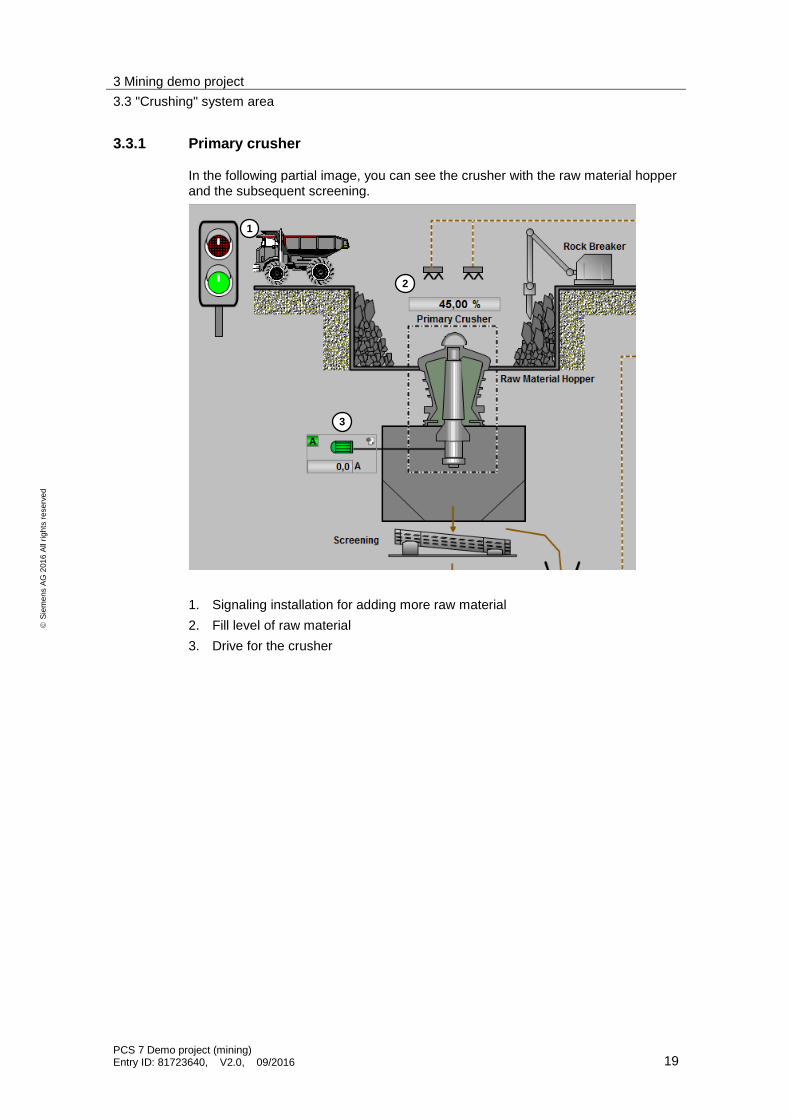
3.3.1 Primary crusher
In the following partial image, you can see the crusher with the raw material hopper and the subsequent screening.
1. Signaling installation for adding more raw material
2. Fill level of raw material
3. Drive for the crusher
1
2
3

3 Mining demo project
3.3 "Crushing" system area
PCS 7 Demo project (mining) Entry ID: 81723640, V2.0, 09/2016 20
S
iem
en
s A
G 2
01
6 A
ll ri
gh
ts r
ese
rve
d
3.3.2 Operator controls for groups, routes and maintenance
Here, you can select routes and start or stop groups.
1. Starts or stops the process of the selected route
2. Route selection – crusher
3. Route selection – stockpile
4. Control of the injection system on belt 1
5. Control of the injection system on belt 2
6. Opens the object browser
7. Opens the maintenance list
8. Opens the info dialog window
1
2
3
4
5
6
7
8

3 Mining demo project
3.3 "Crushing" system area
PCS 7 Demo project (mining) Entry ID: 81723640, V2.0, 09/2016 21
S
iem
en
s A
G 2
01
6 A
ll ri
gh
ts r
ese
rve
d
3.3.3 Conveyor belts
Once crushing is complete, the coarse material is separated from the fine material. The coarse material is transported to the secondary crusher via the first conveyor belt. The finer material is taken directly to the grinder on the second conveyor belt.
1. Dust filter
2. Injection system
3. Belt conveyor drive
4. Safety switch for emergency stop and belt misalignment
3.3.4 Stockpile
Leftover material can be removed from the crusher and stored in a stockpile and, if necessary, fed back into the process. You can define the source of the material feed using the route selection.
1. Signaling installation for filling from the stockpile
2. Fill level of the stockpile
3. Belt conveyor drive
1 2
3
4
1
2
3

3 Mining demo project
3.4 Operator controls
PCS 7 Demo project (mining) Entry ID: 81723640, V2.0, 09/2016 22
S
iem
en
s A
G 2
01
6 A
ll ri
gh
ts r
ese
rve
d
3.4 Operator controls
3.4.1 Faceplates
The system is operated using block icons and the related faceplates.
The design and functionality of the icons and faceplates of MinAS are based on the PCS 7 Advanced Process Library. By clicking on a block icon with the left mouse button, you can open the related faceplate. Some icons, such as an analog value measuring point, feature special functions that can be displayed by clicking the right mouse button. The following views are available for all faceplates:
Standard
Diagnostics
Alarms and messages
Information
Presets for the PLC module (bits feature)
Additional views are available depending on the object, for instance:
Object list
Curve view (trends)
Status call (groups and routes)

3 Mining demo project
3.4 Operator controls
PCS 7 Demo project (mining) Entry ID: 81723640, V2.0, 09/2016 23
S
iem
en
s A
G 2
01
6 A
ll ri
gh
ts r
ese
rve
d
3.4.2 Object browser
The object browser is a tool that can be used to apply filters for specific states of the system objects throughout the entire OS project. You can thus display all of the objects that have a particular status. You can select from the following options:
Objects independent from the Master feature
Interlock bypass
Message available
Power management active
Rapid stop
Service necessary
Object in "Manual" operating mode
Object in "Local" operating mode
Object in "Out of service" operating mode
Object in simulation
The displays for the objects with the "Manual," "Local," "Out of service" and "Simulation" operating modes can be combined.

3 Mining demo project
3.4 Operator controls
PCS 7 Demo project (mining) Entry ID: 81723640, V2.0, 09/2016 24
S
iem
en
s A
G 2
01
6 A
ll ri
gh
ts r
ese
rve
d
3.4.3 Integrated MinAS maintenance
Additional information can be used to configure drives and valves for preventive maintenance. Here, a maintenance view or the object faceplates will provide insight into the operating hours, starts, stops, stops with faults, and downtime.
3.4.4 Integrated MinAS trend
Every analog value that is saved to the Tag Logging archive can added to a special trend display. Using the trend display, you can compare any number of desired analog values with one another. You can configure the trend display by clicking on the analog value icon item with the right mouse button. The trend groups can be saved and reopened as desired.
4 Installation and commissioning of the demo project
4.1 Installing the MinAS
PCS 7 Demo project (mining) Entry ID: 81723640, V2.0, 09/2016 25
S
iem
en
s A
G 2
01
6 A
ll ri
gh
ts r
ese
rve
d
4 Installation and commissioning of the demo project
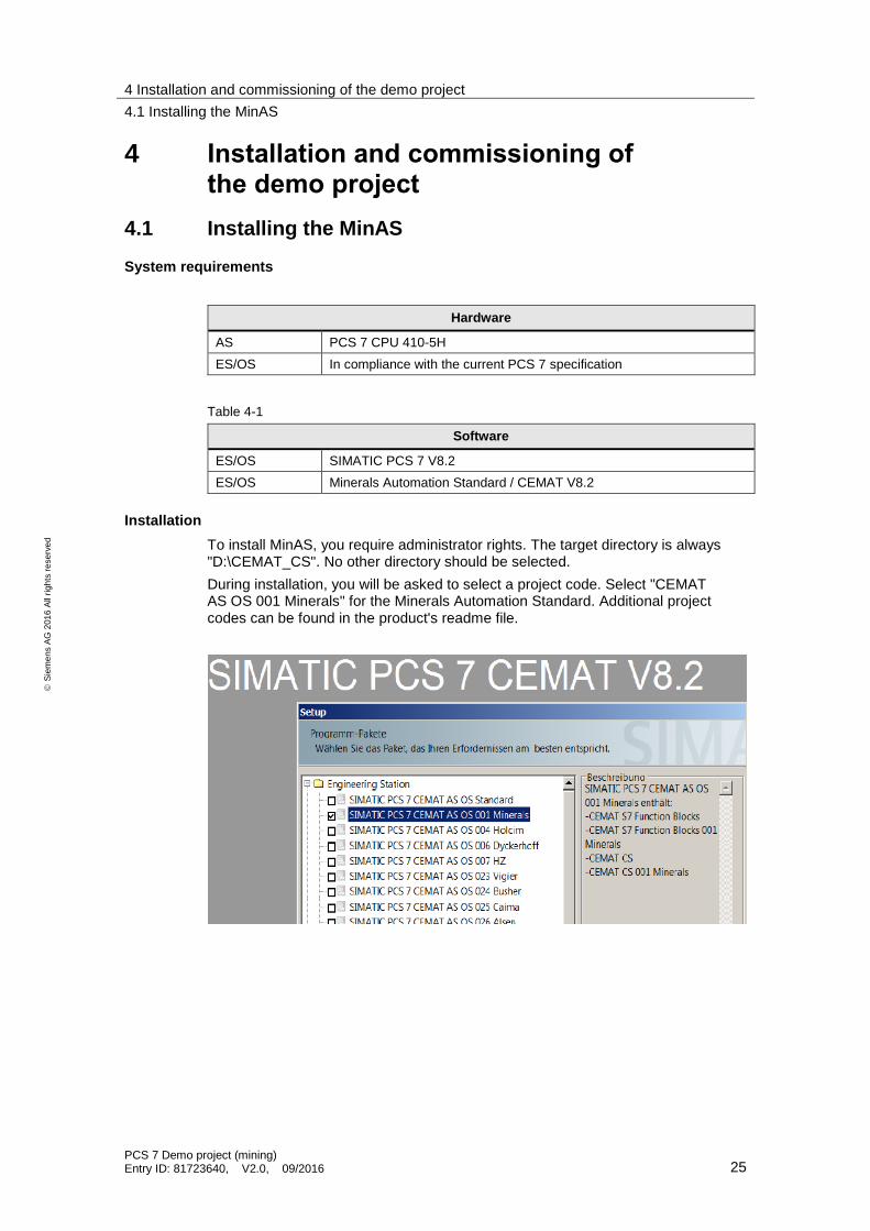
4.1 Installing the MinAS
System requirements
Hardware
AS PCS 7 CPU 410-5H
ES/OS In compliance with the current PCS 7 specification
Table 4-1
Software
ES/OS SIMATIC PCS 7 V8.2
ES/OS Minerals Automation Standard / CEMAT V8.2
Installation
To install MinAS, you require administrator rights. The target directory is always "D:\CEMAT_CS". No other directory should be selected.
During installation, you will be asked to select a project code. Select "CEMAT AS OS 001 Minerals" for the Minerals Automation Standard. Additional project codes can be found in the product's readme file.

4 Installation and commissioning of the demo project
4.2 Installing the demo project
PCS 7 Demo project (mining) Entry ID: 81723640, V2.0, 09/2016 26
S
iem
en
s A
G 2
01
6 A
ll ri
gh
ts r
ese
rve
d
4.2 Installing the demo project
If you haven't done so already, download the "MinAS_demo.zip" file from the Industry Online Support Site and copy the file to your Engineering System.
http://support.automation.siemens.com/WW/view/en/81723640
1. Start SIMATIC Manager.
2. Retrieve the Demo Project.
– Select the menu command "File > Retrieve...".
– Navigate to the storage path containing the "MinAS_demo.zip" file and open the file.
3. Open the retrieved project.
4.3 Loading the AS program
The demo project is configured so that you can use PLCSIM as the automation system. If you would like to load the program in a real automation system, you may need to make adjustments to the hardware configuration and the WinCC connection configuration.
1. Start PLCSIM
– Start PLCSIM by clicking the "Simulation on/off" button in the SIMATIC Manager button bar.
– Select the connection "PLCSIM (TCP/IP)". This switches the PC/PG interface to "PLCSIM.TCPIP.1".
2. Load the configuration and the AS program in the simulator.
3. Set the status of the simulated CPU to "RUN" or "RUN-P".

4 Installation and commissioning of the demo project
4.4 Adapting the computer name
PCS 7 Demo project (mining) Entry ID: 81723640, V2.0, 09/2016 27
S
iem
en
s A
G 2
01
6 A
ll ri
gh
ts r
ese
rve
d
4.4 Adapting the computer name
When opening the OS project, you will receive a note indicating that the configured server is not available.
In order to start the OS runtime, you need to make a one-time change to the computer name in the project. Proceed as follows:
1. Open the editor for the computer properties.
2. In the "General" tab, click the "Use Local Computer Name" button.
3. To apply the new computer name, you must restart the OS project. Close and then reopen the OS project.

4 Installation and commissioning of the demo project
4.5 Customizing the OS project
PCS 7 Demo project (mining) Entry ID: 81723640, V2.0, 09/2016 28
S
iem
en
s A
G 2
01
6 A
ll ri
gh
ts r
ese
rve
d
4.5 Customizing the OS project
If you would like to change the resolution of the OS project to match the screen resolution of your monitor, you will need to follow a few steps. The PCS 7 standard screens can be adjusted using the OS Project Editor. However, MinAS partially uses its own screens, which are overwritten using PCS 7 standard screens when the OS Project Editor is executed. In order to revert back to the typical MinAS user interface, you will need to run the "CematProjectUpdate" tool.
Proceed as follows:
1. If you have not done so yet, open the OS project.
2. Open the OS Project Editor.
– Select the necessary screen resolution.
– Click the "Apply" button.

4 Installation and commissioning of the demo project
4.6 Launching the OS runtime
PCS 7 Demo project (mining) Entry ID: 81723640, V2.0, 09/2016 29
S
iem
en
s A
G 2
01
6 A
ll ri
gh
ts r
ese
rve
d
3. Start the "CematProjectUpdate" tool. You can find the tool in the MinAS installation folder. "D:\CEMAT_CS\CematProjectUpdate.exe"
– Select the target project. The OS project last opened by WinCC is shown here by default.
– Select the screen resolution identical to the one in the OS Project Editor and confirm your selection by clicking the "Res" button.
– Start the OS project update by clicking the "Update OS Project" button.
– Once the update has been successfully completed, you can close the tool.
4. Generate the header file for C scripts.
– Open the "Global Script C" editor.
– Execute the "Generate new header" menu command.
4.6 Launching the OS runtime
When you start the runtime, you will be asked to connect with a valid login name.
Enter the login name "Operator" and password "123456".

4 Installation and commissioning of the demo project
4.7 Initial state of the system
PCS 7 Demo project (mining) Entry ID: 81723640, V2.0, 09/2016 30
S
iem
en
s A
G 2
01
6 A
ll ri
gh
ts r
ese
rve
d
Once you have successfully completed authentication, you can navigate between the plant units using the section buttons.
4.7 Initial state of the system
Navigate to the "Crushing" system area. This screen focuses on the demo project's functionalities.

4 Installation and commissioning of the demo project
4.7 Initial state of the system
PCS 7 Demo project (mining) Entry ID: 81723640, V2.0, 09/2016 31
S
iem
en
s A
G 2
01
6 A
ll ri
gh
ts r
ese
rve
d
When the AS program is restarted, the processing of material by the system is stopped. Simulation of the demo project is activated.
In chapter "6 Further information", you can find more useful information for operation.
The system objects are in the following state:
Drives are off, and valves are closed and in Automatic mode .
The emergency stop and misalignment switches are not active and are in Stop mode.
No route is selected.
The group has not been started.
The signaling installations for filling the primary crusher and the stockpile are "red."
The system objects have the following appearance:
1. Motor stopped
2. Valve closed
3. Analog value display
4. Digital display (misalignment switch with warning and alarm signal)
1
2
3
4
4 Installation and commissioning of the demo project
4.7 Initial state of the system
PCS 7 Demo project (mining) Entry ID: 81723640, V2.0, 09/2016 32
S
iem
en
s A
G 2
01
6 A
ll ri
gh
ts r
ese
rve
d
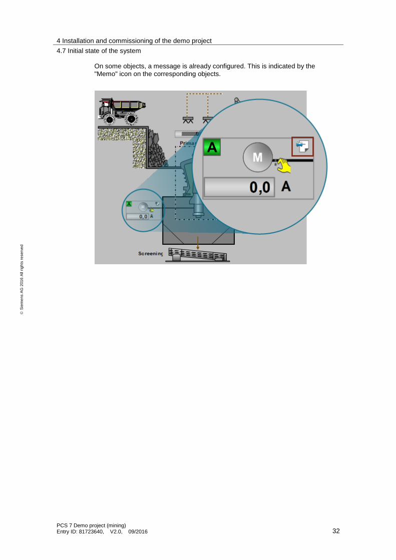
On some objects, a message is already configured. This is indicated by the "Memo" icon on the corresponding objects.

4 Installation and commissioning of the demo project
4.7 Initial state of the system
PCS 7 Demo project (mining) Entry ID: 81723640, V2.0, 09/2016 33
S
iem
en
s A
G 2
01
6 A
ll ri
gh
ts r
ese
rve
d
In the control area for the group, the routes and the diagnostics, you will find the following objects:
Group symbol for operating the plant unit
Route symbol for selecting the material flow from the crusher
Route symbol for selecting the material flow from the stockpile
Symbol for the selection of the injection system on belt 1
Symbol for the selection of the injection system on belt 2
1. The group is stopped and indicates that all connected objects are in Automatic mode .
2. All routes are deselected .
1
2

5 Operating the demo project
5.1 Establishing the plant state using the object browser
PCS 7 Demo project (mining) Entry ID: 81723640, V2.0, 09/2016 34
S
iem
en
s A
G 2
01
6 A
ll ri
gh
ts r
ese
rve
d
5 Operating the demo project The operation and functional properties of the demo project will be demonstrated by means of step-by-step instructions based on the following scenarios:
Establishing the plant state using the object browser
Performing error diagnostics before startup of the groups using "Status call" and the object list.
Starting and stopping system areas (groups)
Faults in groups being started or already in operation
Integrated configuration of MinAS trends
Performing system maintenance using the "Maintenance list"
MinAS alarm view with filter functions
MinAS recipe management
5.1 Establishing the plant state using the object browser
Scenario
In various situations, such as a shift change, it is necessary to quickly obtain an overview of the complete plant state. The MinAS global object browser is available as a powerful tool to help you achieve this. Filters allow you to quickly achieve the desired information, for instance: which objects had their status changed to "Out of service", which objects are in service mode, or which objects have a user note stored on them. From the list of results, you can quickly switch to the faceplate of the desired object, where you can view detailed information about the state of that particular object.
Requirement
The following conditions must be met for this scenario:
Some of the objects have an "Out of service" status. See Chapter: "6.1.2 Changing the operating mode"
A note is already configured on some of the objects. By default, some of the objects in the demo project already have notes. However, if the notes have been deleted, you will find information about how to restore them in chapter: "6.1.3 Storing messages on objects".

5 Operating the demo project
5.1 Establishing the plant state using the object browser
PCS 7 Demo project (mining) Entry ID: 81723640, V2.0, 09/2016 35
S
iem
en
s A
G 2
01
6 A
ll ri
gh
ts r
ese
rve
d
Operation steps
Proceed as follows:
1. Navigate to the "Crusher" plant unit.
2. At the process screen, click on the "ObjectBrowser AS401" button to open the dialog window.
3. Select the "Out of Service" option and confirm your selection by clicking the adjacent button with the green check mark.
1

5 Operating the demo project
5.1 Establishing the plant state using the object browser
PCS 7 Demo project (mining) Entry ID: 81723640, V2.0, 09/2016 36
S
iem
en
s A
G 2
01
6 A
ll ri
gh
ts r
ese
rve
d
4. The list of results then displays all objects whose status is "Out of service". By double-clicking on a list entry, you can then open the faceplate of the desired object.
Note The entries are stored in the results list with a particular color. As can be seen in the example, objects with the "Out of Service" status are highlighted in gray. Objects with a "Simulation" status are shown with an orange background.
5 Operating the demo project
5.1 Establishing the plant state using the object browser
PCS 7 Demo project (mining) Entry ID: 81723640, V2.0, 09/2016 37
S
iem
en
s A
G 2
01
6 A
ll ri
gh
ts r
ese
rve
d
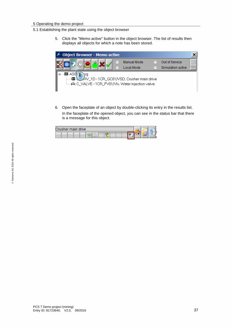
5. Click the "Memo active" button in the object browser. The list of results then displays all objects for which a note has been stored.
6. Open the faceplate of an object by double-clicking its entry in the results list.
In the faceplate of the opened object, you can see in the status bar that there is a message for this object.

5 Operating the demo project
5.1 Establishing the plant state using the object browser
PCS 7 Demo project (mining) Entry ID: 81723640, V2.0, 09/2016 38
S
iem
en
s A
G 2
01
6 A
ll ri
gh
ts r
ese
rve
d
7. Switch to the "Memo" view. Here, you can view the stored message.

5 Operating the demo project
5.2 Performing error diagnostics using "Status call" and the object list
PCS 7 Demo project (mining) Entry ID: 81723640, V2.0, 09/2016 39
S
iem
en
s A
G 2
01
6 A
ll ri
gh
ts r
ese
rve
d
5.2 Performing error diagnostics using "Status call" and the object list
Scenario
For the troubleshooting of assigned objects, MinAS offers efficient tools to determine the status according to the hierarchical structure of a plant unit. In particular, these tools assist the user during the startup or stopping of plant units.
The "Status call" is used for detailed error diagnostics in order to display faults, alarms and interlocks of the assigned measuring points, drives and valves. This allows you to obtain a status from your system before starting it, even if the objects have not yet triggered an alarm due to the fact that they are inactive. This additional function reduces the amount of time necessary for fault diagnostics and makes it possible to directly switch to the particular objects affected from the list of results.
Requirement
The following conditions must be met for this scenario:
The group is stopped (system standstill).
Some of the objects have an "Out of Service" status. See Chapter: "6.1.2 Changing the operating mode"
An emergency stop (rope switch) or a belt misalignment switch (misalignment switch) has been triggered. See Chapter: "6.1.2 Changing the operating mode".

5 Operating the demo project
5.2 Performing error diagnostics using "Status call" and the object list
PCS 7 Demo project (mining) Entry ID: 81723640, V2.0, 09/2016 40
S
iem
en
s A
G 2
01
6 A
ll ri
gh
ts r
ese
rve
d
Operation steps
Proceed as follows:
1. You can already tell from the block icon that there is a fault in one of the group objects. However, because the system is not in operation, no alarm has been sent yet to the PCS 7 alarm logging system.

5 Operating the demo project
5.2 Performing error diagnostics using "Status call" and the object list
PCS 7 Demo project (mining) Entry ID: 81723640, V2.0, 09/2016 41
S
iem
en
s A
G 2
01
6 A
ll ri
gh
ts r
ese
rve
d
2. Open the faceplate for the route and switch to the "Status call" view. Here, you can see a preview of the message and react to the situation accordingly before commissioning the conveyor belts and triggering a real alarm.
3. Switch to the "Object list" view. Here, you will find all objects that belong to the group. Search for the objects that have an "Out of Service" status. These are highlighted in gray.

5 Operating the demo project
5.2 Performing error diagnostics using "Status call" and the object list
PCS 7 Demo project (mining) Entry ID: 81723640, V2.0, 09/2016 42
S
iem
en
s A
G 2
01
6 A
ll ri
gh
ts r
ese
rve
d
4. By double-clicking one of the objects, you can open the related faceplate. Here, any notes that have been stored will indicate the reason for the status.

5 Operating the demo project
5.3 Starting and stopping system areas (groups)
PCS 7 Demo project (mining) Entry ID: 81723640, V2.0, 09/2016 43
S
iem
en
s A
G 2
01
6 A
ll ri
gh
ts r
ese
rve
d
5. Change the status from "Out of Service" to "Automatic" for all objects.
5.3 Starting and stopping system areas (groups)
Scenario
Technological process stages, such as the transport of material via conveyor belts, flotation cells, or systems for grinding extracted ore, can be combined into groups with MinAS. Operation and error diagnostics are greatly simplified with the use of groups. Grouped drives and valves can be set to a particular status in a parallel or sequential manner with a simple mouse click. Fault conditions are displayed and analyzed centrally in the group.
Requirements
The following conditions must be met for this scenario:
The objects are in Automatic mode. See Chapter: "6.1.2 Changing the operating mode"
The group objects must be ready / there may not be any triggered alarms. See Chapter: "6.1.1 Process simulation"

5 Operating the demo project
5.3 Starting and stopping system areas (groups)
PCS 7 Demo project (mining) Entry ID: 81723640, V2.0, 09/2016 44
S
iem
en
s A
G 2
01
6 A
ll ri
gh
ts r
ese
rve
d
Operation steps
Proceed as follows:
1. Select a route to start from within the group. To do this, open the faceplate for the "Feed from Crusher" route. Click the "Sel." button to select this route.
2. Open the faceplate for the group and start the group by clicking the "Start" button.
Note The startup of the group is indicated by the arrow in the group symbol.

5 Operating the demo project
5.3 Starting and stopping system areas (groups)
PCS 7 Demo project (mining) Entry ID: 81723640, V2.0, 09/2016 45
S
iem
en
s A
G 2
01
6 A
ll ri
gh
ts r
ese
rve
d
3. The group startup passes through multiple phases.
Phase 1: "Time for startup warning": Length of time for the output of a signal indicating that the system is starting up.
Phase 2: "Waiting time": Length of time between the alarm signal and the system startup.
Phase 3: "Startup release time": The drives are started, valves are opened, etc. If any of the plant units fail to report operation once the startup time has expired, then a fault message is displayed and the group is stopped again.
Note Operation of the group is indicated by the O in the group symbol.
1
2
3

5 Operating the demo project
5.3 Starting and stopping system areas (groups)
PCS 7 Demo project (mining) Entry ID: 81723640, V2.0, 09/2016 46
S
iem
en
s A
G 2
01
6 A
ll ri
gh
ts r
ese
rve
d
4. In the system process, the drives of the last conveyor belts are started first in order to avoid an accumulation of material. The last thing to be started is the drive for the crusher. Once the crusher is up and running, the signaling installation for ore filling switches to green.
The block icon for the routes and the groups show the following status:
– The "Start/Stop Feeding" group is active.
– The "Feed from Crusher" route is active.
– The "Feed from Stockpile" route is deselected and locked (interlock).
5. To switch the route, open the faceplate for the "Feed from Stockpile" route and click the "Sel." button. In the block icon, the "P" indicates that this route has been preselected.

5 Operating the demo project
5.3 Starting and stopping system areas (groups)
PCS 7 Demo project (mining) Entry ID: 81723640, V2.0, 09/2016 47
S
iem
en
s A
G 2
01
6 A
ll ri
gh
ts r
ese
rve
d
6. Deselect the currently active "Feed from Crusher" route. Open the faceplate and click the "Desel." button. Since the route is currently still locked (interlock), only the color of the "S" icon changes from green to white. The "Feed from Crusher" route is still active.
7. Restart the group to apply the route change.

5 Operating the demo project
5.3 Starting and stopping system areas (groups)
PCS 7 Demo project (mining) Entry ID: 81723640, V2.0, 09/2016 48
S
iem
en
s A
G 2
01
6 A
ll ri
gh
ts r
ese
rve
d
8. Once the startup sequence is complete, the process screen will show that the crusher and the 1st conveyor belt were shut down and that the conveyor belt from the storage silo was activated instead. The signaling installation for the crusher indicates that no more material may be added.
9. To stop the system again, open the faceplate for the group and click the "Stop" button.
Note The shutdown of the system is indicated by the arrow in the group symbol.

5 Operating the demo project
5.4 Faults in groups being started or already in operation
PCS 7 Demo project (mining) Entry ID: 81723640, V2.0, 09/2016 49
S
iem
en
s A
G 2
01
6 A
ll ri
gh
ts r
ese
rve
d
10. Once the "shut down" process is complete, the system is once again in the original state.
5.4 Faults in groups being started or already in operation
Scenario
If a fault occurs during operation of a system, the affected plant unit is stopped. As a result, troubleshooting must be performed on the affected objects in order to solve the problem. MinAS provides different functions that help the user keep downtime as short as possible during troubleshooting.
Together with the information view, the object list offers information about the status and process signals for all of the objects in a group.

5 Operating the demo project
5.4 Faults in groups being started or already in operation
PCS 7 Demo project (mining) Entry ID: 81723640, V2.0, 09/2016 50
S
iem
en
s A
G 2
01
6 A
ll ri
gh
ts r
ese
rve
d
Requirement
The following conditions must be met for this scenario:
The group is active or currently starting up. See Chapter: "5.3 Starting and stopping system areas (groups)"
An emergency stop signal (e.g., RS_BC01_S4701) has been triggered. See Chapter: "6.1.1 Process simulation".
Operation steps
Proceed as follows:
1. An emergency stop was triggered in the area of the first conveyor belt, causing an alarm to be triggered by the PCS 7 alarm logging system and to be displayed in the alarm line of the runtime interface. The block icons for the route and the group are marked with an alarm icon. As a result of the alarm, the drive of the first conveyor belt was stopped and locked to prevent a restart.

5 Operating the demo project
5.4 Faults in groups being started or already in operation
PCS 7 Demo project (mining) Entry ID: 81723640, V2.0, 09/2016 51
S
iem
en
s A
G 2
01
6 A
ll ri
gh
ts r
ese
rve
d
2. To determine the cause of the alarm, open the faceplate for the group and switch to the "Object list" view. The red symbols in the list mark the object that triggered the system stop.
3. By double-clicking the list entry, you can open the related faceplate and use it to obtain detailed information.

5 Operating the demo project
5.4 Faults in groups being started or already in operation
PCS 7 Demo project (mining) Entry ID: 81723640, V2.0, 09/2016 52
S
iem
en
s A
G 2
01
6 A
ll ri
gh
ts r
ese
rve
d
4. Use the simulator block to reset the emergency stop signal again. See Chapter: "6.1.1 Process simulation".
5. Before you can put the faulty conveyor belt back into operation, you must acknowledge the current fault and reset the belt conveyor drive again.
You can acknowledge the fault using the acknowledgment button next to the PCS 7 alarm line, in the PCS 7 alarm view or in the CEMAT alarm view.
6. Start the group again by opening the faceplate and clicking the "Start" button.

5 Operating the demo project
5.5 Integrated MinAS trend configuration
PCS 7 Demo project (mining) Entry ID: 81723640, V2.0, 09/2016 53
S
iem
en
s A
G 2
01
6 A
ll ri
gh
ts r
ese
rve
d
5.5 Integrated MinAS trend configuration
Scenario
With the trend-configuration option integrated in MinAS, you can configure customized groups of trends and save them to be displayed again as desired. Trends provide the user with information about the operating state of the system or the performance of individual components.
You can easily activate the trend configuration directly from the process screen by selecting the desired measured values.
Requirement
There are no particular requirements for this scenario.
Operation steps
Proceed as follows:
1. To access the trend group configuration dialog window, click the unit of the desired analog value with the right mouse button. You can also add other values by right-clicking on the unit of the analog measuring point. The trend configuration dialog window will remain open during this step.
Add the following analog values to the trend configuration:
(1) Conveyor belt 1 material flow
(2) Conveyor belt 2 material flow
(3) Raw material fill Level
1
2
3

5 Operating the demo project
5.5 Integrated MinAS trend configuration
PCS 7 Demo project (mining) Entry ID: 81723640, V2.0, 09/2016 54
S
iem
en
s A
G 2
01
6 A
ll ri
gh
ts r
ese
rve
d
2. At the configuration dialog window for the trends, you can see the analog values selected, administer the groups and call the trend display.
(1) Selected analog values
(2) Saved trend configurations
(3) Button for starting the trend display
3. The trend display shows the tag values in different colors. The display can be switched between current values and values from the archive.
1
2
3
1 2
3
4

5 Operating the demo project
5.6 Performing system maintenance using the "Maintenance list"
PCS 7 Demo project (mining) Entry ID: 81723640, V2.0, 09/2016 55
S
iem
en
s A
G 2
01
6 A
ll ri
gh
ts r
ese
rve
d
(1) Online tags
(2) Archive tags
(3) Button for navigating through archived values
(4) Button for displaying current values
5.6 Performing system maintenance using the "Maintenance list"
Scenario
For drives and valves, MinAS offers additional information concerning preventive maintenance and availability. Here, a MinAS maintenance view or the object faceplates will provide insight into the operating hours, starts, stops, stops with faults, and downtime.
The drives and valves can be configured using the following maintenance settings:
Fixed maintenance interval
Maintenance after predetermined number of operating hours
Maintenance after specific number of starts (motor) or openings and closings (valve).
This enables the creation of statistics, e.g. for operating hours, stops or downtime due to faults. In addition, the maintenance information can be used to derive maintenance alarms or be made available to other external maintenance systems in the block.
Requirement
There are no particular requirements for this scenario.

5 Operating the demo project
5.6 Performing system maintenance using the "Maintenance list"
PCS 7 Demo project (mining) Entry ID: 81723640, V2.0, 09/2016 56
S
iem
en
s A
G 2
01
6 A
ll ri
gh
ts r
ese
rve
d
Operation steps
Proceed as follows:
1. Configure a service interval for a few motors and valves and start the maintenance service. To do this, open the faceplate for a motor or a valve and switch to the "Maintenance" view. The button is located on the second level of the view buttons. This level can be activated by clicking the "..." button.
(1) Select the type of maintenance interval and configure the time or the number of starts.
(2) Here, you can configure the time or the number of starts that will result in maintenance being demanded.
(3) You can activate the maintenance function by clicking the "Start" button.
1
2
3

5 Operating the demo project
5.6 Performing system maintenance using the "Maintenance list"
PCS 7 Demo project (mining) Entry ID: 81723640, V2.0, 09/2016 57
S
iem
en
s A
G 2
01
6 A
ll ri
gh
ts r
ese
rve
d
2. A maintenance demanded notification is indicated by the spanner icon . Detailed information can be found in the faceplate of the object requiring maintenance.
(1) Maintenance status of the object
(2) Status of the maintenance service
(3) Maintenance personnel status (manual maintenance)
(4) Button for resetting the maintenance function
1
2
3 4

5 Operating the demo project
5.7 MinAS alarm view with filter functions
PCS 7 Demo project (mining) Entry ID: 81723640, V2.0, 09/2016 58
S
iem
en
s A
G 2
01
6 A
ll ri
gh
ts r
ese
rve
d
3. You can obtain an overall status for all objects that have a configured maintenance function using the "CEMAT Maintenance List." You can open the overview in the demo project by clicking the "Maintenance List" button.
5.7 MinAS alarm view with filter functions
Scenario
The messages and alarms in the system remain a crucial source of information for determining the system operating mode. The analysis of these alarms also enables you to draw conclusions about unexpected behavior from plant units or their components. For these tasks, MinAS offers the user an advanced alarm view with special functions that can be saved. The advanced alarm view is simple to handle and is used to provide selective information about the location and type of fault.
Requirement
At least one object has triggered an alarm in the PCS 7 alarm logging system. For this to be possible, the group must already be started when a fault occurs. See Chapter: "6.1.1 Process simulation".
Operation steps
Proceed as follows:
1. Click the button for the MinAS alarm view in the PCS 7 OS key area.

5 Operating the demo project
5.7 MinAS alarm view with filter functions
PCS 7 Demo project (mining) Entry ID: 81723640, V2.0, 09/2016 59
S
iem
en
s A
G 2
01
6 A
ll ri
gh
ts r
ese
rve
d
2. Using the area buttons, you can show or hide the display for messages from the corresponding system area.
3. Additional filter settings are available if you switch the alarm view to the long-term archive.
(1) Switch between the current and long-term archives; close the alarm view
(2) Refresh the filter settings
(3) Save and load filter settings
(4) Additional filter settings for event, message tag, and message class
1
2 3 4

5 Operating the demo project
5.8 MinAS recipe management
PCS 7 Demo project (mining) Entry ID: 81723640, V2.0, 09/2016 60
S
iem
en
s A
G 2
01
6 A
ll ri
gh
ts r
ese
rve
d
5.8 MinAS recipe management
Scenario
The main part of cement production is the grinding process, where the clinker base material is ground according to different recipes together with additives such as fly ash, gypsum and lime.
The SPC blocks in CEMAT MinAs V8.2 enable a recipe-controlled production process for manufacturing various types of cement.
The following example shows the basic functionalities for the recipe management of a cement grinding plant using SPC.
Recipe management with 3 recipes (for 3 cement types)
2 recipe modules for assignment of setpoint parameters (one "Absolute REAL" and one "Relative Totalizing REAL")
Materials management for feed hoppers 1 to 3 (clinker, gypsum and fly ash)
Requirement
There are no particular requirements for this scenario.

5 Operating the demo project
5.8 MinAS recipe management
PCS 7 Demo project (mining) Entry ID: 81723640, V2.0, 09/2016 61
S
iem
en
s A
G 2
01
6 A
ll ri
gh
ts r
ese
rve
d
Operation steps
Proceed as follows:
1. Navigate to the plant unit "SPC Example".
2. Click on the blue "Recipe Management" button in the process picture to open the SPC Recipe Manager dialog window.
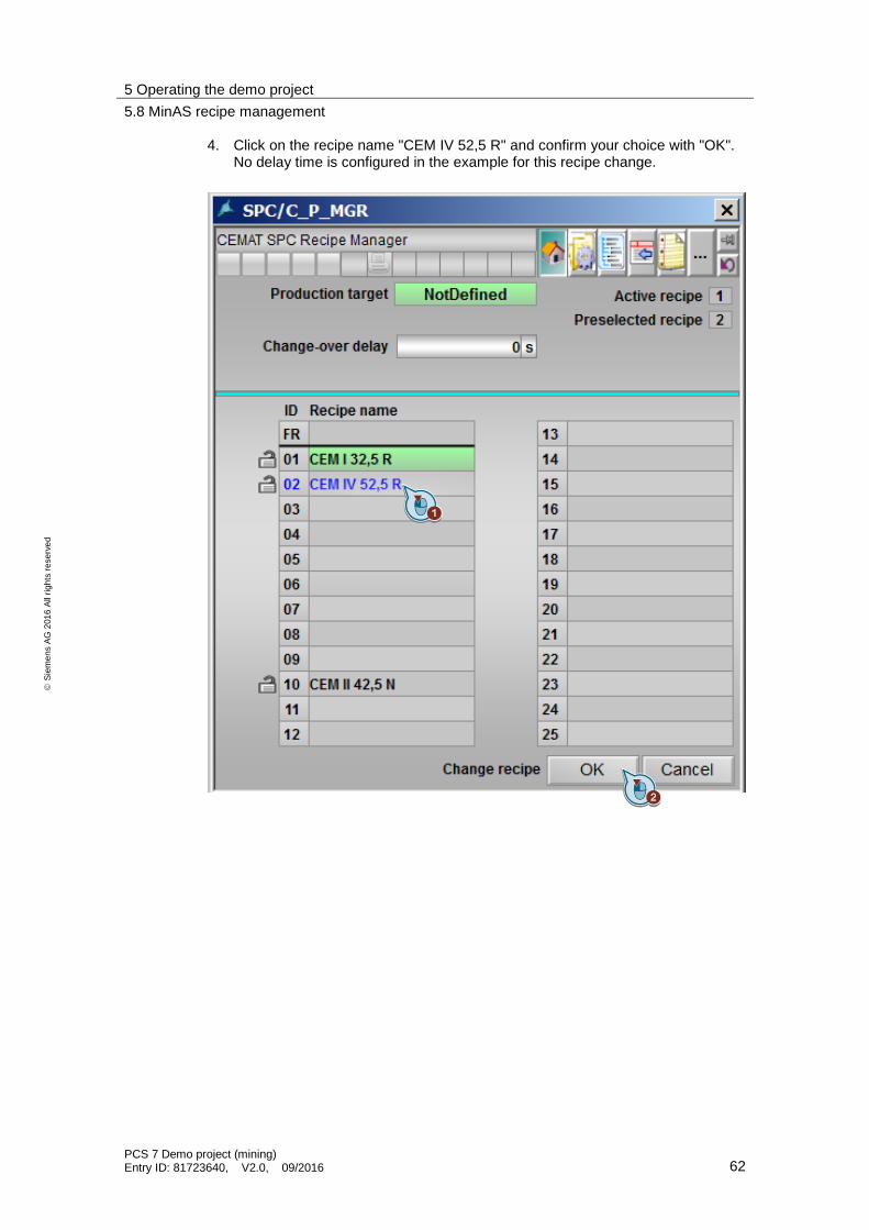
3. Here you can modify recipes and assign parameters for delay time. The active recipe is marked with a green color.
5 Operating the demo project
5.8 MinAS recipe management
PCS 7 Demo project (mining) Entry ID: 81723640, V2.0, 09/2016 62
S
iem
en
s A
G 2
01
6 A
ll ri
gh
ts r
ese
rve
d
4. Click on the recipe name "CEM IV 52,5 R" and confirm your choice with "OK". No delay time is configured in the example for this recipe change.

5 Operating the demo project
5.8 MinAS recipe management
PCS 7 Demo project (mining) Entry ID: 81723640, V2.0, 09/2016 63
S
iem
en
s A
G 2
01
6 A
ll ri
gh
ts r
ese
rve
d
5. The recipe "CEM IV 52,5 R" is now active and marked with a green background color.

5 Operating the demo project
5.8 MinAS recipe management
PCS 7 Demo project (mining) Entry ID: 81723640, V2.0, 09/2016 64
S
iem
en
s A
G 2
01
6 A
ll ri
gh
ts r
ese
rve
d
6. Switch back to the recipe "CEM I 32,5 R" and confirm your selection with OK. Since there is a predefined delay time for the recipe "CEM I 32,5 R", the recipe change is only completed after the delay time elapses. The operator can skip this change-over delay by clicking the Skip button.

5 Operating the demo project
5.8 MinAS recipe management
PCS 7 Demo project (mining) Entry ID: 81723640, V2.0, 09/2016 65
S
iem
en
s A
G 2
01
6 A
ll ri
gh
ts r
ese
rve
d
7. You can see all the modules of all recipes by clicking the "Object list".

5 Operating the demo project
5.8 MinAS recipe management
PCS 7 Demo project (mining) Entry ID: 81723640, V2.0, 09/2016 66
S
iem
en
s A
G 2
01
6 A
ll ri
gh
ts r
ese
rve
d
8. In "Object list" you can see all the modules and you can double-click an entry to access the desired module. Double-click on the module "C_PM_RTR". This module contains the desired quantity of fresh material and the distribution (in percent) of the individual components: clinker, gypsum and fly ash.

5 Operating the demo project
5.8 MinAS recipe management
PCS 7 Demo project (mining) Entry ID: 81723640, V2.0, 09/2016 67
S
iem
en
s A
G 2
01
6 A
ll ri
gh
ts r
ese
rve
d
9. In this dialog window, you can change the setpoints for gypsum or fly ash, whereby the clinker quantity is adjusted automatically. Enter 5 % for gypsum and press the "Enter" button.
Note Note: The setpoints are entered in C_PM_RTR as a percentage of a reference size (fresh material, in this case).

5 Operating the demo project
5.8 MinAS recipe management
PCS 7 Demo project (mining) Entry ID: 81723640, V2.0, 09/2016 68
S
iem
en
s A
G 2
01
6 A
ll ri
gh
ts r
ese
rve
d
10. Then click "OK" to confirm your entry.

5 Operating the demo project
5.8 MinAS recipe management
PCS 7 Demo project (mining) Entry ID: 81723640, V2.0, 09/2016 69
S
iem
en
s A
G 2
01
6 A
ll ri
gh
ts r
ese
rve
d
11. Now, click on the "Diagnostics" button.
12. In this dialog window, you to change the setpoint limits.

5 Operating the demo project
5.8 MinAS recipe management
PCS 7 Demo project (mining) Entry ID: 81723640, V2.0, 09/2016 70
S
iem
en
s A
G 2
01
6 A
ll ri
gh
ts r
ese
rve
d
13. Close the C_PM_RTR dialog window and double-click on the C_PM_AR module. This module includes all setpoints for rotational speeds and positions for units required for cement grinding.
14. Navigate to the "Diagnostics" view to change sample setpoints.

5 Operating the demo project
5.8 MinAS recipe management
PCS 7 Demo project (mining) Entry ID: 81723640, V2.0, 09/2016 71
S
iem
en
s A
G 2
01
6 A
ll ri
gh
ts r
ese
rve
d
15. The setpoints changed by the operator are marked with a blue font color and must be additionally confirmed because there is no other way for multiple changes to be applied concurrently. For instance, the setpoint 80 for the separator and press the "Enter" button.
16. To confirm your setpoint change, click OK.

5 Operating the demo project
5.8 MinAS recipe management
PCS 7 Demo project (mining) Entry ID: 81723640, V2.0, 09/2016 72
S
iem
en
s A
G 2
01
6 A
ll ri
gh
ts r
ese
rve
d
17. As a result, you will see that the new setpoint is accepted by the module.
18. Navigate to the "SPC Example" plant unit and click on the blue "Feeding hoppers" button in the process picture to open the SPC Material Manager dialog window.

5 Operating the demo project
5.8 MinAS recipe management
PCS 7 Demo project (mining) Entry ID: 81723640, V2.0, 09/2016 73
S
iem
en
s A
G 2
01
6 A
ll ri
gh
ts r
ese
rve
d
19. In this example, this SPC Material Manager is for materials management of feed hoppers 1 to 3 (clinker, gypsum and fly ash)
The setpoint value specifications for the material scales are supplied by the Material Manager because the assignment (feed hopper to material) can change and therefore the right scale is always addressed.
The operator can assign materials to the storage locations during execution time.

5 Operating the demo project
5.8 MinAS recipe management
PCS 7 Demo project (mining) Entry ID: 81723640, V2.0, 09/2016 74
S
iem
en
s A
G 2
01
6 A
ll ri
gh
ts r
ese
rve
d
20. Switch to "Diagnostics" view. Here you can assign materials to the various storage locations as long as the actual value on the scale (= conveyed material) is zero, i.e., the storage location is not used.

5 Operating the demo project
5.8 MinAS recipe management
PCS 7 Demo project (mining) Entry ID: 81723640, V2.0, 09/2016 75
S
iem
en
s A
G 2
01
6 A
ll ri
gh
ts r
ese
rve
d
21. Here you can see the assignment of material to the storage locations. The selection keys are not released for as long as material is being conveyed.
5 Operating the demo project
5.8 MinAS recipe management
PCS 7 Demo project (mining) Entry ID: 81723640, V2.0, 09/2016 76
S
iem
en
s A
G 2
01
6 A
ll ri
gh
ts r
ese
rve
d
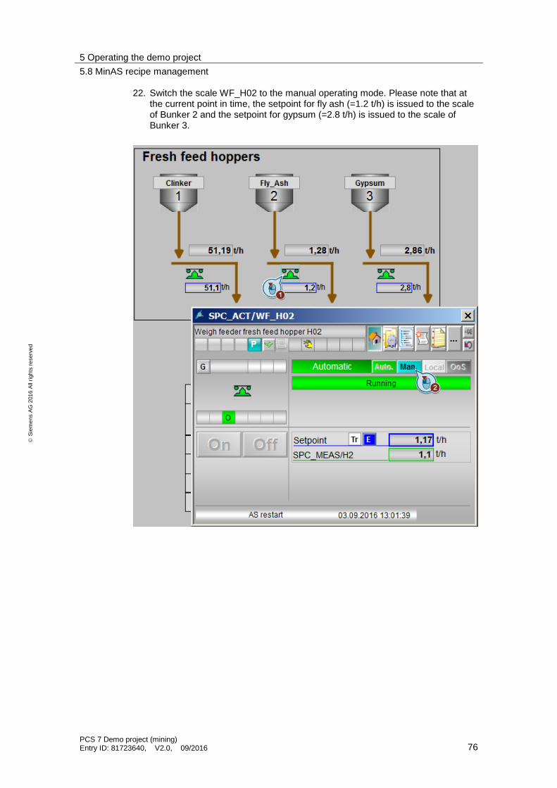
22. Switch the scale WF_H02 to the manual operating mode. Please note that at the current point in time, the setpoint for fly ash (=1.2 t/h) is issued to the scale of Bunker 2 and the setpoint for gypsum (=2.8 t/h) is issued to the scale of Bunker 3.

5 Operating the demo project
5.8 MinAS recipe management
PCS 7 Demo project (mining) Entry ID: 81723640, V2.0, 09/2016 77
S
iem
en
s A
G 2
01
6 A
ll ri
gh
ts r
ese
rve
d
23. Stop the motor.
24. Also set the scale WF_H03 to the manual operating mode and stop the motor.

5 Operating the demo project
5.8 MinAS recipe management
PCS 7 Demo project (mining) Entry ID: 81723640, V2.0, 09/2016 78
S
iem
en
s A
G 2
01
6 A
ll ri
gh
ts r
ese
rve
d
25. Then you can change the material assignment of these two storage locations.

5 Operating the demo project
5.8 MinAS recipe management
PCS 7 Demo project (mining) Entry ID: 81723640, V2.0, 09/2016 79
S
iem
en
s A
G 2
01
6 A
ll ri
gh
ts r
ese
rve
d
26. Assign the gypsum material to storage location Fresh_Feed_H02 (=Bunker 02) and the fly ash material to Fresh_Feed_H03 (=Bunker 03) and confirm your selection with OK.

5 Operating the demo project
5.8 MinAS recipe management
PCS 7 Demo project (mining) Entry ID: 81723640, V2.0, 09/2016 80
S
iem
en
s A
G 2
01
6 A
ll ri
gh
ts r
ese
rve
d
27. Click the "On" button to start the motor.
28. Switch to Automatic mode.
Also start the WF_H03 motor and switch to Automatic mode.

5 Operating the demo project
5.8 MinAS recipe management
PCS 7 Demo project (mining) Entry ID: 81723640, V2.0, 09/2016 81
S
iem
en
s A
G 2
01
6 A
ll ri
gh
ts r
ese
rve
d
29. Now you can see that the setpoints for gypsum and fly ash are supplied in reverse order (i.e., the right way) to the scale.
The materials management for cement silos 1 to 5 is only for display purposes
in the process picture and has no further function in the example project.

6 Further information
6.1 Application notes
PCS 7 Demo project (mining) Entry ID: 81723640, V2.0, 09/2016 82
S
iem
en
s A
G 2
01
6 A
ll ri
gh
ts r
ese
rve
d
6 Further information
6.1 Application notes
6.1.1 Process simulation
In order to allow you test a project properly even without connected hardware, CEMAT has an internal simulation that is only active during the sequence test.
For the purpose of this demo project, the sequence Test Mode has already been activated in the system chart SYSPLC01.
The following functions can be executed in Sequence Test Mode:
Save
Load
Pause (or Hold)
The hold function serves for freezing the state of all CEMAT objects.
The current state of all CEMAT blocks is saved by clicking the Save button.
Load is used for loading the last saved state.
The Diagnostics view of the CEMAT object faceplates enables you to influence the hardware-related block inputs.

6 Further information
6.1 Application notes
PCS 7 Demo project (mining) Entry ID: 81723640, V2.0, 09/2016 83
S
iem
en
s A
G 2
01
6 A
ll ri
gh
ts r
ese
rve
d
6.1.2 Changing the operating mode
To change the operating mode of a motor, a valve or a measuring point, proceed as follows:
1. Open the faceplate of an object.
2. Select the "Out of Service" mode.

6 Further information
6.2 Tips and tricks
PCS 7 Demo project (mining) Entry ID: 81723640, V2.0, 09/2016 84
S
iem
en
s A
G 2
01
6 A
ll ri
gh
ts r
ese
rve
d
6.1.3 Storing messages on objects
You can store messages on the objects in the project. With the object browser, it is easy to find all of the objects that have a message. To add a message to an object, proceed as follows:
1. Open the faceplate for an object.
2. Switch to the "memo" view.
3. The "Note" tab contains a text field in which you can leave your message.
4. Save the text you have entered.
Once you have completed this, a message icon is displayed in the faceplate header.
6.2 Tips and tricks
Trend groups
There are different ways of operating the MinAS block icons for analog value acquisition. You have the following options:
Left mouse click: The faceplate for the selected analog value is opened.
Right mouse click on the analog value: A trend display is opened which shows the archived value with the limit values that are currently set.
Right mouse click on the unit of the analog value: The configuration dialog window is opened for the MinAS trend display.

6 Further information
6.2 Tips and tricks
PCS 7 Demo project (mining) Entry ID: 81723640, V2.0, 09/2016 85
S
iem
en
s A
G 2
01
6 A
ll ri
gh
ts r
ese
rve
d
Adjusting the OS image resolution
The standard PCS 7 tool for adjusting the image resolution is the OS Project Editor. However, the Project Editor also replaces the special MinAS screens.
To revert back to the normal MinAS interface after changing the resolution, you can use the "CematProjectUpdate" tool.
Perform the steps illustrated in chapter "4.5 Customizing the OS project".
Displaying the measuring point names
To display the measuring point names at the process screen, you can use the function integrated in MinAS. To do this, click the following button:

7 References
PCS 7 Demo project (mining) Entry ID: 81723640, V2.0, 09/2016 86
S
iem
en
s A
G 2
01
6 A
ll ri
gh
ts r
ese
rve
d
7 References Table 7-1
Topic
\1\ Siemens Industry Online Support
https://support.industry.siemens.com
\2\ Download page of this entry https://support.industry.siemens.com/cs/ww/en/view/81723640
\3\ Minerals Automation Standard http://www.siemens.com/minas
\4\ Mining industry in the Industry Online Support https://support.industry.siemens.com/cs/ww/en/ps/21155/ae
8 History
Table 8-1
Version Date Change
V1.0 Feb. 2014 First edition
V2.0 Sept 2016 Updating to PCS 7 V8.2 and MinAS / CEMAT V8.2