application for communication · message orientation the transmission is organized in frames which...
TRANSCRIPT

Application for Communication
Comparison of Data Transmission via one and via four parallel ISO on TCP Connections on Industrial Ethernet

ISO on TCP connections on Industrial Ethernet
Rev. A- Final 16.02.2004 2/38
Cop
yrig
ht ©
Sie
men
s AG
200
5 A
ll rig
hts
rese
rved
20
9873
59_I
SOon
TCP_
DO
KU_v
10_e
Warranty, Liability and Support
We do not accept any liability for the information contained in this document. Any claims against us - based on whatever legal reason - resulting from the use of the examples, information, programs, engineering and performance data etc., described in this document shall be excluded. Such an exclusion shall not apply in the case of mandatory liability, e.g. under the German Product Liability Act (“Produkthaftungsgesetz”), in case of intent, gross negligence, or injury of life, body or health, guarantee for the quality of a product, fraudulent concealment of a deficiency or breach of a condition which goes to the root of the contract (“wesentliche Vertragspflichten”). However, claims arising from a breach of a condition which goes to the root of the contract shall be limited to the foreseeable damage which is intrinsic to the contract, unless caused by intent or gross negligence or based on mandatory liability for injury of life, body or health. The above provisions does not imply a change in the burden of proof to your detriment. The Application Examples are not binding and do not claim to be complete regarding the circuits shown, equipping and any eventuality. They do not represent customer-specific solutions. They are only intended to provide support for typical applications. You are responsible in ensuring that the described products are correctly used. These Application Examples do not relieve you of the responsibility in safely and professionally using, installing, operating and servicing equipment. When using these Application Examples, you recognize that Siemens cannot be made liable for any damage/claims beyond the liability clause described above. We reserve the right to make changes to these Application Examples at any time without prior notice. If there are any deviations between the recommendations provided in these Application Examples and other Siemens publications - e.g. Catalogs - then the contents of the other documents have priority.
Copyright© 2004 Siemens A&D. It is not permissible to transfer or copy these Application Examples or excerpts of them without first having prior authorization from Siemens A&D in writing. For questions about this document please use the following e-mail-address: [email protected]
ISO on TCP connections on Industrial Ethernet
Rev. A- Final 16.02.2004 3/38
Cop
yrig
ht ©
Sie
men
s AG
200
5 A
ll rig
hts
rese
rved
20
9873
59_I
SOon
TCP_
DO
KU_v
10_e
Table of Contents
1 Task Specification...................................................................................... 4 2 Principle of the Automation Solution....................................................... 5 2.1 Required components .................................................................................. 6 3 Function Mechanisms and Program Structures ..................................... 8 3.1 “ISO on TCP” based on “TCP“ ..................................................................... 8 3.2 User interface SEND / RECEIVE ............................................................... 10 3.2.1 AG_SEND / AG_LSEND............................................................................ 11 3.2.2 AG_RECEIVE / AG_LRECEIVE ................................................................ 13 3.2.3 Distinguishing criteria of the blocks............................................................ 15 3.3 Principle structure of this example ............................................................. 16 3.4 Program structures..................................................................................... 17 3.4.1 Block structure of the sender ..................................................................... 17 3.4.2 Block structure of the receiver.................................................................... 18 3.4.3 Other data blocks used .............................................................................. 20 3.5 Program procedure of the sender .............................................................. 21 3.5.1 Program procedure “Test_Manager” (FB 10)............................................. 21 3.5.2 Program procedure “Multiple_Send” (FB 1) ............................................... 24 3.5.3 Program procedure “Send_Data” (FB 31).................................................. 27 3.6 Program procedure of the receiver ............................................................ 29 3.6.1 Program procedure “Multiple_Receive” (FB 2) .......................................... 29 3.6.2 Program procedure “Combiner” (FB 37) .................................................... 31 4 Determined Measured Values ................................................................. 33 5 Installation of Hardware and Software................................................... 34 5.1 Hardware configuration .............................................................................. 34 5.2 Installation of the software ......................................................................... 34 5.3 The core configurations of the application ................................................. 35 5.4 Operator control and monitoring ................................................................ 36
ISO on TCP connections on Industrial Ethernet
Rev. A- Final 16.02.2004 4/38
Cop
yrig
ht ©
Sie
men
s AG
200
5 A
ll rig
hts
rese
rved
20
9873
59_I
SOon
TCP_
DO
KU_v
10_e
1 Task Specification
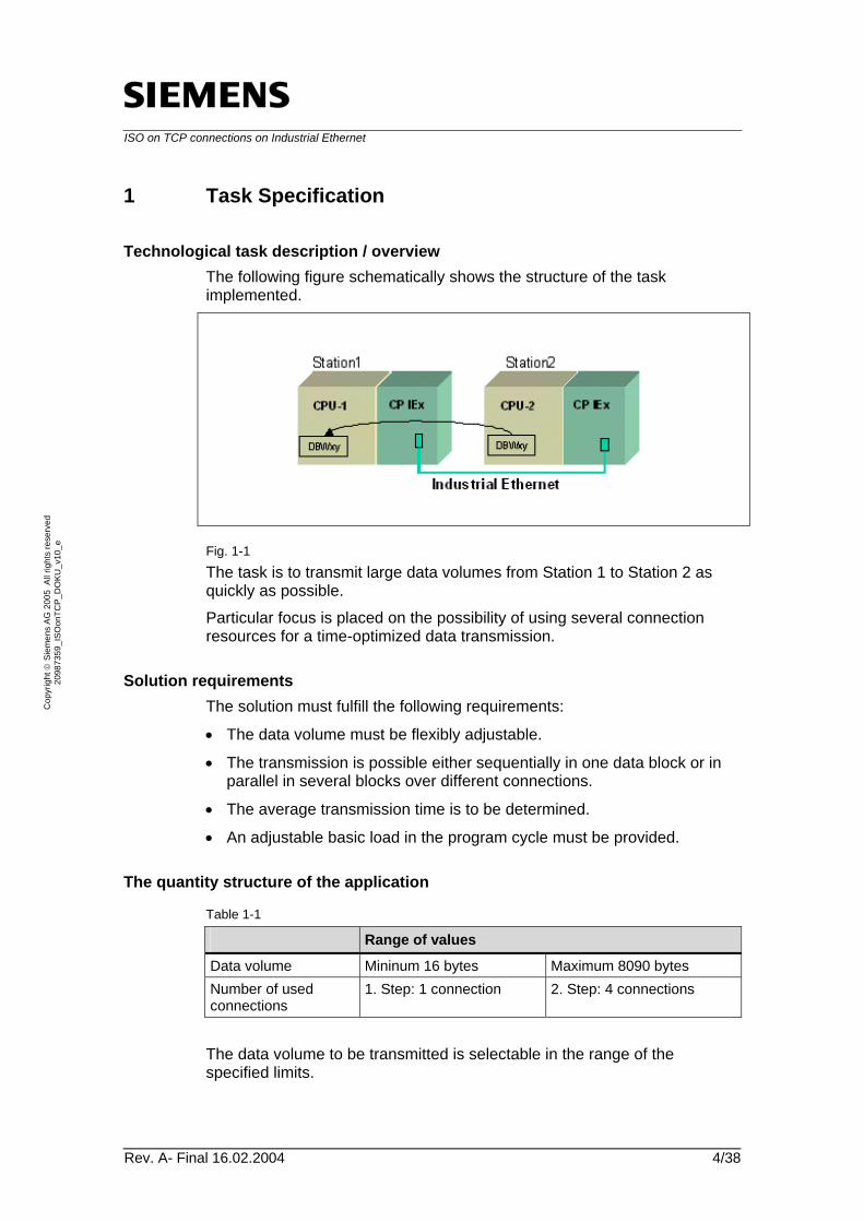
Technological task description / overview The following figure schematically shows the structure of the task implemented.
Fig. 1-1 The task is to transmit large data volumes from Station 1 to Station 2 as quickly as possible. Particular focus is placed on the possibility of using several connection resources for a time-optimized data transmission.
Solution requirements The solution must fulfill the following requirements:
• The data volume must be flexibly adjustable.
• The transmission is possible either sequentially in one data block or in parallel in several blocks over different connections.
• The average transmission time is to be determined.
• An adjustable basic load in the program cycle must be provided.
The quantity structure of the application
Table 1-1
Range of values
Data volume Mininum 16 bytes Maximum 8090 bytes Number of used connections
1. Step: 1 connection 2. Step: 4 connections
The data volume to be transmitted is selectable in the range of the specified limits.
ISO on TCP connections on Industrial Ethernet
Rev. A- Final 16.02.2004 5/38
Cop
yrig
ht ©
Sie
men
s AG
200
5 A
ll rig
hts
rese
rved
20
9873
59_I
SOon
TCP_
DO
KU_v
10_e
2 Principle of the Automation Solution
Introduction
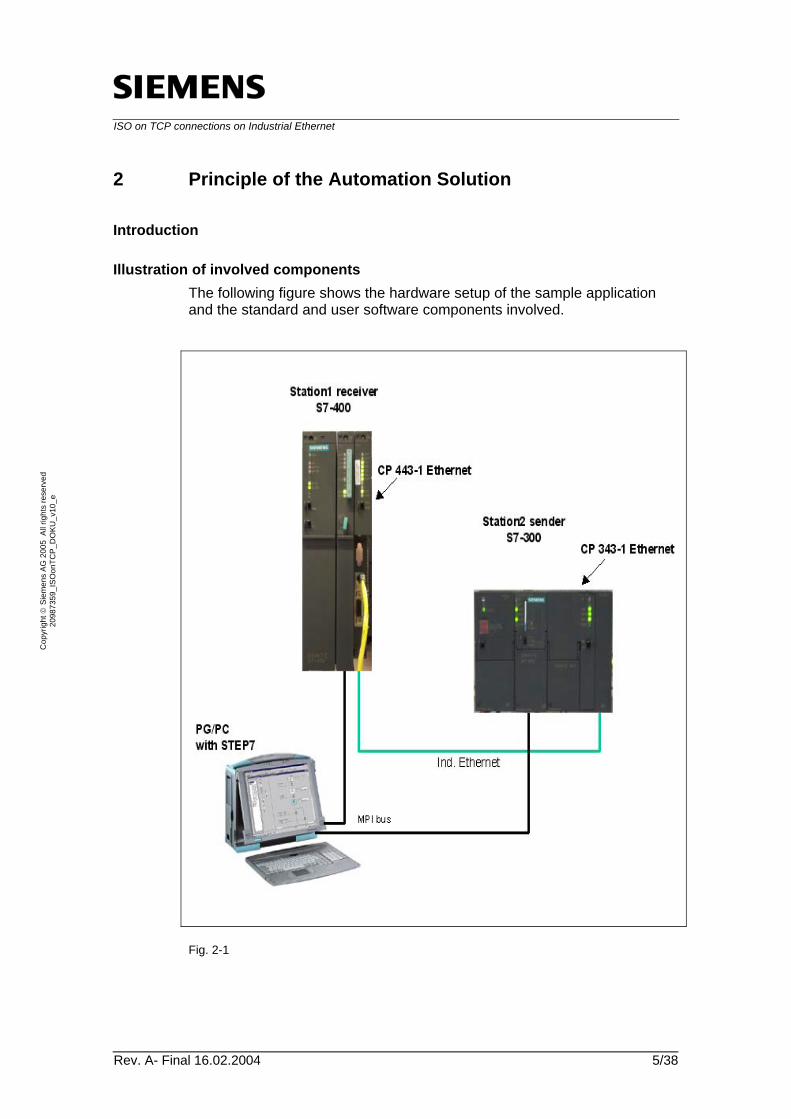
Illustration of involved components The following figure shows the hardware setup of the sample application and the standard and user software components involved.
Fig. 2-1
ISO on TCP connections on Industrial Ethernet
Rev. A- Final 16.02.2004 6/38
Cop
yrig
ht ©
Sie
men
s AG
200
5 A
ll rig
hts
rese
rved
20
9873
59_I
SOon
TCP_
DO
KU_v
10_e
2.1 Required components
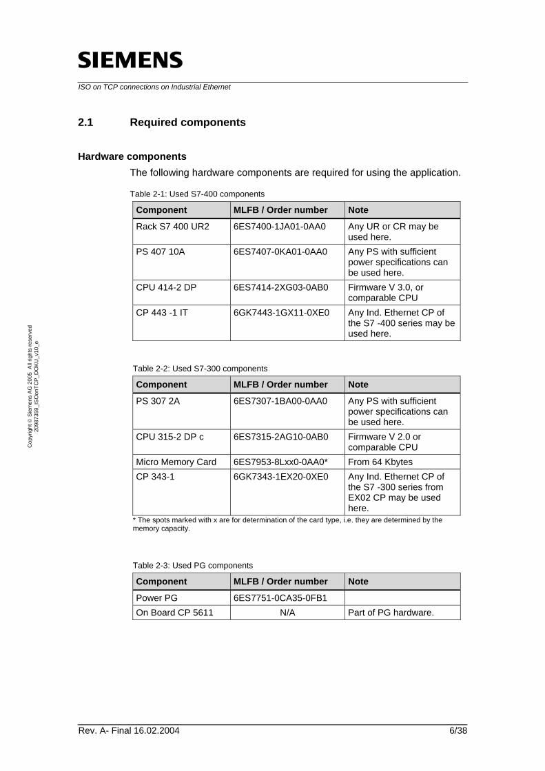
Hardware components The following hardware components are required for using the application.
Table 2-1: Used S7-400 components
Component MLFB / Order number Note
Rack S7 400 UR2 6ES7400-1JA01-0AA0 Any UR or CR may be used here.
PS 407 10A 6ES7407-0KA01-0AA0 Any PS with sufficient power specifications can be used here.
CPU 414-2 DP 6ES7414-2XG03-0AB0 Firmware V 3.0, or comparable CPU
CP 443 -1 IT 6GK7443-1GX11-0XE0 Any Ind. Ethernet CP of the S7 -400 series may be used here.
Table 2-2: Used S7-300 components
Component MLFB / Order number Note
PS 307 2A 6ES7307-1BA00-0AA0 Any PS with sufficient power specifications can be used here.
CPU 315-2 DP c 6ES7315-2AG10-0AB0 Firmware V 2.0 or comparable CPU
Micro Memory Card 6ES7953-8Lxx0-0AA0* From 64 Kbytes CP 343-1 6GK7343-1EX20-0XE0 Any Ind. Ethernet CP of
the S7 -300 series from EX02 CP may be used here.
* The spots marked with x are for determination of the card type, i.e. they are determined by the memory capacity.
Table 2-3: Used PG components
Component MLFB / Order number Note
Power PG 6ES7751-0CA35-0FB1 On Board CP 5611 N/A Part of PG hardware.

ISO on TCP connections on Industrial Ethernet
Rev. A- Final 16.02.2004 7/38
Cop
yrig
ht ©
Sie
men
s AG
200
5 A
ll rig
hts
rese
rved
20
9873
59_I
SOon
TCP_
DO
KU_v
10_e
Software components The following software components are required for using the application.
Table 2-4
Component MLFB / Order number Note
Step 7 V 5.2 6ES7810-4CC06-0YX0 Already included in the Power PG price.
NCM S7 Profibus N/A Part of Step 7 SW. SIMATIC S7-SCL V 5.1 + SP 5
6ES7811-1CC04-0YX0 Single License Version
Example project The example application consists of the following components:
Table 2-5: Used application components
Component Note
20987359_ISOonTCP_DOKU_v10.zip
This packed file contains the hardware configuration for both stations, the connection configuration as well as the application programs in AWL and SCL source code (except the system functions and functions for AG_SEND and AG_RECEIVE) .
20987359_ISOonTCP_DOKU_v10_d.pdf 20987359_ISOonTCP_DOKU_v10_e.pdf
This documentation
Further information on commissioning hardware and software is available in chapter 5 ”Installation of Hardware and Software”.
ISO on TCP connections on Industrial Ethernet
Rev. A- Final 16.02.2004 8/38
Cop
yrig
ht ©
Sie
men
s AG
200
5 A
ll rig
hts
rese
rved
20
9873
59_I
SOon
TCP_
DO
KU_v
10_e
3 Function Mechanisms and Program Structures
The following chapter briefly describes the “ISO on TCP” protocol which the present application is based on.
3.1 “ISO on TCP” based on “TCP“
The “Ethernet” network In the IEEE802.3 standard only physical boundary conditions such as transmission medium, distances, connections and access methods are defined for the Ethernet. To be able to establish a communication between two or more stations, an additional rule type for data transmission control – protocol is needed to be created.
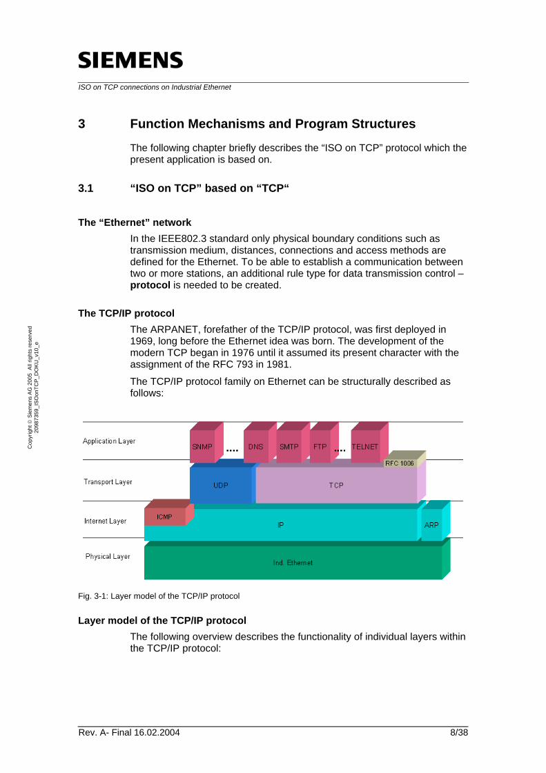
The TCP/IP protocol The ARPANET, forefather of the TCP/IP protocol, was first deployed in 1969, long before the Ethernet idea was born. The development of the modern TCP began in 1976 until it assumed its present character with the assignment of the RFC 793 in 1981. The TCP/IP protocol family on Ethernet can be structurally described as follows:
Fig. 3-1: Layer model of the TCP/IP protocol
Layer model of the TCP/IP protocol The following overview describes the functionality of individual layers within the TCP/IP protocol:
ISO on TCP connections on Industrial Ethernet
Rev. A- Final 16.02.2004 9/38
Cop
yrig
ht ©
Sie
men
s AG
200
5 A
ll rig
hts
rese
rved
20
9873
59_I
SOon
TCP_
DO
KU_v
10_e
Table 3-1
Layer Description
Application Layer The top layer of the TCP/IP layer model is called application layer. This layer offers a number of application protocols which many applications are based on. These application protocols are based either on UDP, TCP or on both of them. One of these supplements to the TCP protocol is RFC 1006 “ISO Transport Services on top of the TCP“.
Transport Layer The transport layer is based on the internet layer. It forms the actual data interface for applications or protocols which are based on TCP/IP. This layer is mainly divided into two large, equal blocks: • The UDP (User Datagram Protocol) which functions as a
datagram interface and transmits encapsulated data via a not acknowledged, connectionless networking service.
• The TCP (Transmission Control Protocol), an acknowledged, connection-oriented protocol, transmits data in a byte flow.
Internet Layer The internet layer is based on the physical layer and can be compared with the network layer of the ISO-OSI layer model. The function of IP (Internet Protocol) is to safely transfer data from one network to another until the destination is reached. This transmission is independent of the selected path and of the used network. Besides the Internet Protocol, an ARP (Address Resolution Protocol) is also located at the Internet layer. The IP has an unacknowledged functionality, therefore secure data transmission must be ensured at one of the higher layers.
Physical Layer The basis of the layer model is a network layer (physical layer). According to the TCP/IP philosophy, this layer is kept as flexible as possible which enables a quick connection to new networks or networks of different types so that the TCP/IP protocol is as portable as possible.
Although not related to the ISO-OSI reference model, the structure of TCP/IP is very similar to it. The ISO-OSI reference model was “completed” in 1983 and the TCP/IP model in 1981. Nevertheless, there is an obvious similarity between the TCP/IP and ISO-OSI reference model.
RFC 1006: “ISO Transport Services on top of the TCP” As opposed to the ISO transport service (ISO 8072), the TCP protocol, based on the transport layer, is not message-oriented but rather stream-oriented. Yet, message-oriented functionality is essential for the most applications.
ISO on TCP connections on Industrial Ethernet
Rev. A- Final 16.02.2004 10/38
Cop
yrig
ht ©
Sie
men
s AG
200
5 A
ll rig
hts
rese
rved
20
9873
59_I
SOon
TCP_
DO
KU_v
10_e
Table 3-2
Term Description
Message orientation The transmission is organized in frames which structurally combine user data with additional information for transmission of data.
Stream orientation For a stream-oriented data transmission a fixed data stream must be established between two communication partners. The user data is transmitted within this data stream. Upon transmission of user data, the data stream remains available.
A message-oriented approach is useful especially for the SIMATIC environment. A change-over from ISO transport to TCP transport should be done easily and without any complications. In order to achieve this, an additional protocol was necessary on top of the TCP. To remain as standardized as possible, the present RFC 1006 “ISO Transport Services on top of the TCP” standard has been chosen. The protocol, on the basis of RFC 1006, is mainly identical to ISO 8073, which also forms the basis of the ISO transport protocol. Problems typical to TCP, for example, a missing end-of-data marker, were thus avoided, and the advantages of the ISO and TCP/IP systems such as routability and an end-of-frame marker successfully combined. The protocol is supported on the so-called “Open Port“ Port 102 and operates in the same way as the ISO transport protocol with TSAPs. The ISO on TCP protocol as well as ISO transport protocol operate within SIMATIC using the SEND/RECEIVE interface.
3.2 User interface SEND / RECEIVE
The following section explains the SIMATIC function interface for communication using the ISO on TCP protocol.
ISO on TCP connections on Industrial Ethernet
Rev. A- Final 16.02.2004 11/38
Cop
yrig
ht ©
Sie
men
s AG
200
5 A
ll rig
hts
rese
rved
20
9873
59_I
SOon
TCP_
DO
KU_v
10_e
3.2.1 AG_SEND / AG_LSEND
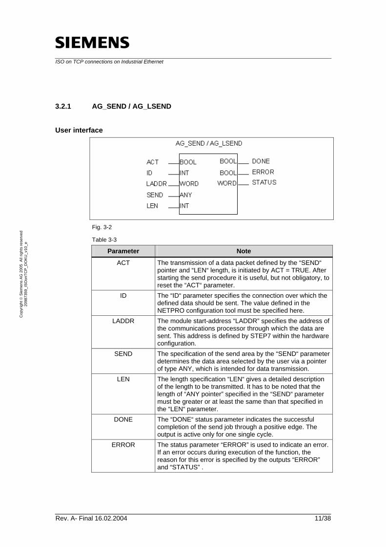
User interface
Fig. 3-2
Table 3-3
Parameter Note
ACT The transmission of a data packet defined by the “SEND“ pointer and “LEN“ length, is initiated by ACT = TRUE. After starting the send procedure it is useful, but not obligatory, to reset the “ACT“ parameter.
ID The “ID“ parameter specifies the connection over which the defined data should be sent. The value defined in the NETPRO configuration tool must be specified here.
LADDR The module start-address “LADDR” specifies the address of the communications processor through which the data are sent. This address is defined by STEP7 within the hardware configuration.
SEND The specification of the send area by the “SEND“ parameter determines the data area selected by the user via a pointer of type ANY, which is intended for data transmission.
LEN The length specification “LEN“ gives a detailed description of the length to be transmitted. It has to be noted that the length of “ANY pointer” specified in the “SEND“ parameter must be greater or at least the same than that specified in the “LEN“ parameter.
DONE The “DONE“ status parameter indicates the successful completion of the send job through a positive edge. The output is active only for one single cycle.
ERROR The status parameter “ERROR” is used to indicate an error. If an error occurs during execution of the function, the reason for this error is specified by the outputs “ERROR” and “STATUS” .
ISO on TCP connections on Industrial Ethernet
Rev. A- Final 16.02.2004 12/38
Cop
yrig
ht ©
Sie
men
s AG
200
5 A
ll rig
hts
rese
rved
20
9873
59_I
SOon
TCP_
DO
KU_v
10_e
Parameter Note
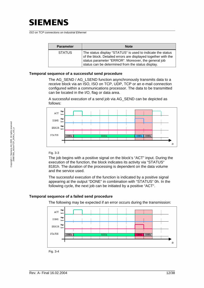
STATUS The status display “STATUS“ is used to indicate the status of the block. Detailed errors are displayed together with the status parameter “ERROR“. Moreover, the general job status can be determined from the status display.
Temporal sequence of a successful send procedure The AG_SEND / AG_LSEND function asynchronously transmits data to a receive block via an ISO, ISO on TCP, UDP, TCP or an e-mail connection configured within a communications processor. The data to be transmitted can be located in the I/O, flag or data area. A successful execution of a send job via AG_SEND can be depicted as follows:
Fig. 3-3 The job begins with a positive signal on the block’s “ACT” input. During the execution of the function, the block indicates its activity via “STATUS“ 8181h. The duration of the processing is dependent on the data volume and the service used. The successful execution of the function is indicated by a positive signal appearing at the output “DONE“ in combination with “STATUS“ 0h. In the following cycle, the next job can be initiated by a positive “ACT“.
Temporal sequence of a failed send procedure The following may be expected if an error occurs during the transmission:
Fig. 3-4
ISO on TCP connections on Industrial Ethernet
Rev. A- Final 16.02.2004 13/38
Cop
yrig
ht ©
Sie
men
s AG
200
5 A
ll rig
hts
rese
rved
20
9873
59_I
SOon
TCP_
DO
KU_v
10_e
This job also begins with a positive signal on the block’s “ACT” input. Here also, the block’s activity is indicated by “STATUS“ 8181h while the function is being executed. An error is displayed on the “ERROR“ output together with the corresponding “STATUS“ as soon as it is reported by the communications processor. (The status used here is just an example). This information is only available for a read cycle. In this case also, the send job can be tried again after the corresponding reaction time.
Note: Relevant error codes Detailed error messages relevant to this function can be found in the online-help or in the “SIMATIC NET NCM S7 for Industrial Ethernet“ documentation, in chapter 6.3.
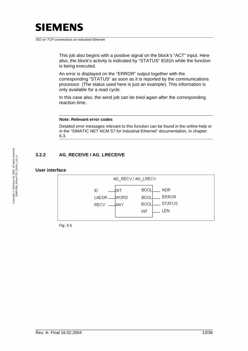
3.2.2 AG_RECEIVE / AG_LRECEIVE
User interface
Fig. 3-5

ISO on TCP connections on Industrial Ethernet
Rev. A- Final 16.02.2004 14/38
Cop
yrig
ht ©
Sie
men
s AG
200
5 A
ll rig
hts
rese
rved
20
9873
59_I
SOon
TCP_
DO
KU_v
10_e
Table 3-4
Parameter Note
ID The “ID“ parameter specifies the connection over which the defined data should be sent. The values defined in the NETPRO configuration tool must be specified here.
LADDR The module start-address “LADDR” specifies the address of the communications processor through which the data are sent. This address is defined by STEP7 within the hardware configuration.
RECV The specification of the receive area by the “RECV“ parameter determines the data area which the user has selected using an ANY pointer intended for reception of data.
NDR The “NDR“ status parameter indicates the reception of new data through a positive edge. The output is active only for one single cycle.
ERROR The status parameter “ERROR” is used to indicate an error. If an error occurs during execution of the function, the reason for this error is specified by the “ERROR” and “STATUS” outputs.
STATUS The status display “STATUS“ is used to indicate the status of the block. Detailed error information is displayed together with the “ERROR“ status parameter. Moreover, the general job status can be determined from the status display.
LEN The output value “LEN“ shows the actual length of the transmitted data in the receive area. The “LEN“ length specification must always be shorter or the same as that in the “RECV“ receive area.
Temporal sequence of a successful receiving procedure The AG_RECEIVE / AG_LRECEIVE function asynchronously receives data from a send block via an ISO, ISO on TCP, UDP or a TCP connection configured within a communications processor. The target data area can either be I/O, flag or data area. A successful execution of a receive job via AG_RECEIVE can be depicted as follows:
Fig. 3-6 A receive job is active as soon as it is called. The “STATUS“ 8180h is output until the job is processed and no date has been completely accepted in the receive buffer (there is no data available yet).
ISO on TCP connections on Industrial Ethernet
Rev. A- Final 16.02.2004 15/38
Cop
yrig
ht ©
Sie
men
s AG
200
5 A
ll rig
hts
rese
rved
20
9873
59_I
SOon
TCP_
DO
KU_v
10_e
The successful completion of a receive function is indicated by a positive impulse on the “NDR” output. The 0h value is currently output by the “STATUS“ parameter and the data length of the received message by the “LEN“ parameter. (8092 dec. in this example) In the next call cycle the “STATUS“ (8180h) “There is no data available yet“ is output.
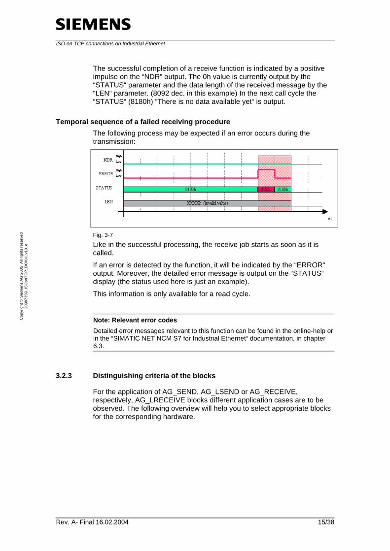
Temporal sequence of a failed receiving procedure The following process may be expected if an error occurs during the transmission:
Fig. 3-7 Like in the successful processing, the receive job starts as soon as it is called. If an error is detected by the function, it will be indicated by the “ERROR“ output. Moreover, the detailed error message is output on the “STATUS“ display (the status used here is just an example). This information is only available for a read cycle.
Note: Relevant error codes Detailed error messages relevant to this function can be found in the online-help or in the “SIMATIC NET NCM S7 for Industrial Ethernet“ documentation, in chapter 6.3.
3.2.3 Distinguishing criteria of the blocks
For the application of AG_SEND, AG_LSEND or AG_RECEIVE, respectively, AG_LRECEIVE blocks different application cases are to be observed. The following overview will help you to select appropriate blocks for the corresponding hardware.

ISO on TCP connections on Industrial Ethernet
Rev. A- Final 16.02.2004 16/38
Cop
yrig
ht ©
Sie
men
s AG
200
5 A
ll rig
hts
rese
rved
20
9873
59_I
SOon
TCP_
DO
KU_v
10_e
Table 3-5
Services S7-300 CPs > EX11
S7-300 CPs > EX11
S7-400 CPs
ISO, ISO on TCP, UDP connection
AG_SEND V 4.1 AG_RECV V 4.6
Data < 240 bytes AG_SEND V 4.1 AG_RECV V 4.6 Data > 240 bytes AG_LSEND V 3.0 AG_LRECV V 3.0
Data < 240 bytes AG_SEND V 1.1 AG_RECV V 1.1 Data > 240 bytes AG_LSEND V 3.0 AG_LRECV V 3.0
TCP connection AG_SEND V 4.1 AG_RECV V 4.6
AG_LSEND V 3.0 AG_LRECV V 3.0
AG_LSEND V 3.0 AG_LRECV V 3.0
3.3 Principle structure of this example
Introduction In this example, a constant data volume is alternately transmitted to the receiver
• in one block over a connection (Step 1), and
• in several partial blocks over a parallel connection (Step 2) The following data flow model illustrates the steps used in this example.
Data flow model
Fig. 3-8 The “identical“ data is transmitted in two modes.
• In the first step, the maximum volume of data is transmitted to a target station by means of one send job.
ISO on TCP connections on Industrial Ethernet
Rev. A- Final 16.02.2004 17/38
Cop
yrig
ht ©
Sie
men
s AG
200
5 A
ll rig
hts
rese
rved
20
9873
59_I
SOon
TCP_
DO
KU_v
10_e
• In the second step, the transmission is done by dynamically splitting the data into 4 equal areas, simultaneously using 4 connections and via the same CP. Subsequently, the data is recombined in the receiver in correct order.
Additionally, the runtimes of both steps are determined and output on the job block. The maximum, minimum and average runtimes of the jobs are determined using statistical functions.
3.4 Program structures
The following chapter will give you an overview of the used block structure in the source code of this example.
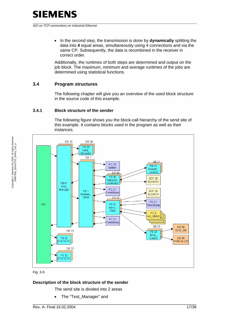
3.4.1 Block structure of the sender
The following figure shows you the block-call hierarchy of the send site of this example. It contains blocks used in the program as well as their instances.
Fig. 3-9
Description of the block structure of the sender The send site is divided into 2 areas
• The “Test_Manager” and
ISO on TCP connections on Industrial Ethernet
Rev. A- Final 16.02.2004 18/38
Cop
yrig
ht ©
Sie
men
s AG
200
5 A
ll rig
hts
rese
rved
20
9873
59_I
SOon
TCP_
DO
KU_v
10_e
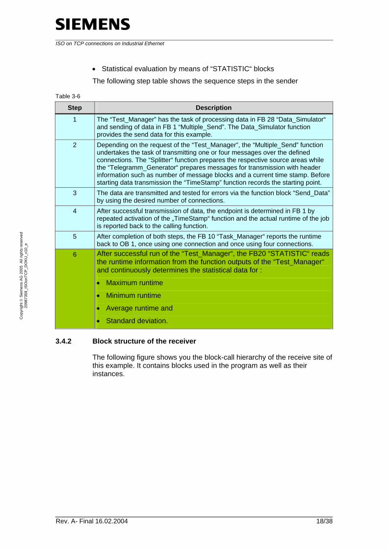
• Statistical evaluation by means of “STATISTIC“ blocks The following step table shows the sequence steps in the sender
Table 3-6
Step Description
1 The “Test_Manager” has the task of processing data in FB 28 “Data_Simulator“ and sending of data in FB 1 “Multiple_Send”. The Data_Simulator function provides the send data for this example.
2 Depending on the request of the “Test_Manager”, the “Multiple_Send” function undertakes the task of transmitting one or four messages over the defined connections. The “Splitter“ function prepares the respective source areas while the “Telegramm_Generator“ prepares messages for transmission with header information such as number of message blocks and a current time stamp. Before starting data transmission the “TimeStamp” function records the starting point.
3 The data are transmitted and tested for errors via the function block “Send_Data” by using the desired number of connections.
4 After successful transmission of data, the endpoint is determined in FB 1 by repeated activation of the „TimeStamp“ function and the actual runtime of the job is reported back to the calling function.
5 After completion of both steps, the FB 10 “Task_Manager“ reports the runtime back to OB 1, once using one connection and once using four connections.
6 After successful run of the “Test_Manager“, the FB20 “STATISTIC“ reads the runtime information from the function outputs of the “Test_Manager“ and continuously determines the statistical data for :
• Maximum runtime
• Minimum runtime
• Average runtime and
• Standard deviation.
3.4.2 Block structure of the receiver
The following figure shows you the block-call hierarchy of the receive site of this example. It contains blocks used in the program as well as their instances.

ISO on TCP connections on Industrial Ethernet
Rev. A- Final 16.02.2004 19/38
Cop
yrig
ht ©
Sie
men
s AG
200
5 A
ll rig
hts
rese
rved
20
9873
59_I
SOon
TCP_
DO
KU_v
10_e
Fig. 3-10
Description of the block structure of the receiver The following step table shows the sequence steps in the receiver:
Table 3-7
Step Description
1 The “Multiple_Receive“ function block cyclically monitors all four connections using the “Receive_Data“ function.
2 The “Receive_Data“ function block receives message blocks and, if required, records occurred errors of the receive blocks.
3 The “Combiner“ block is started to combine the data segments to the data block as soon as the “Multiple_Receive“ block detects that the defined number of messages is received by the “Receive_Data“ block.
4 The “Combiner“ function block reads the user data from individual message blocks and successively copies them to the target area.

ISO on TCP connections on Industrial Ethernet
Rev. A- Final 16.02.2004 20/38
Cop
yrig
ht ©
Sie
men
s AG
200
5 A
ll rig
hts
rese
rved
20
9873
59_I
SOon
TCP_
DO
KU_v
10_e
3.4.3 Other data blocks used
Table 3-8
Name Usage Sender
DB 2 „GLOBAL_DB“ The data block contains a structure for each of the 4 possible connections that has the following data:
• Source pointer which describes the data area to be sent in the source data.
• Buffer pointer which indicate the send area in the send buffer.
• ACT, DONE and ERROR block parameters
DB 11 “Data_Source“ This data block forms the data area for the data simulator where simulated data are stored as input data.
DB100 “Buffer_Send“ This data block is the data buffer where predefined messages, including header, are stored before being sent via the send functions.
Receiver DB 10 – 13
“Receive_Segment1 – 4“ These four data blocks are receive buffers of the respective receive blocks.
DB 101 “Buffer Receive“ This data block is the final storage location of the data received. The received data segments without the respective header are successively stored within this location.
ISO on TCP connections on Industrial Ethernet
Rev. A- Final 16.02.2004 21/38
Cop
yrig
ht ©
Sie
men
s AG
200
5 A
ll rig
hts
rese
rved
20
9873
59_I
SOon
TCP_
DO
KU_v
10_e
3.5 Program procedure of the sender
3.5.1 Program procedure “Test_Manager” (FB 10)
Table 3-9
Flowchart Description
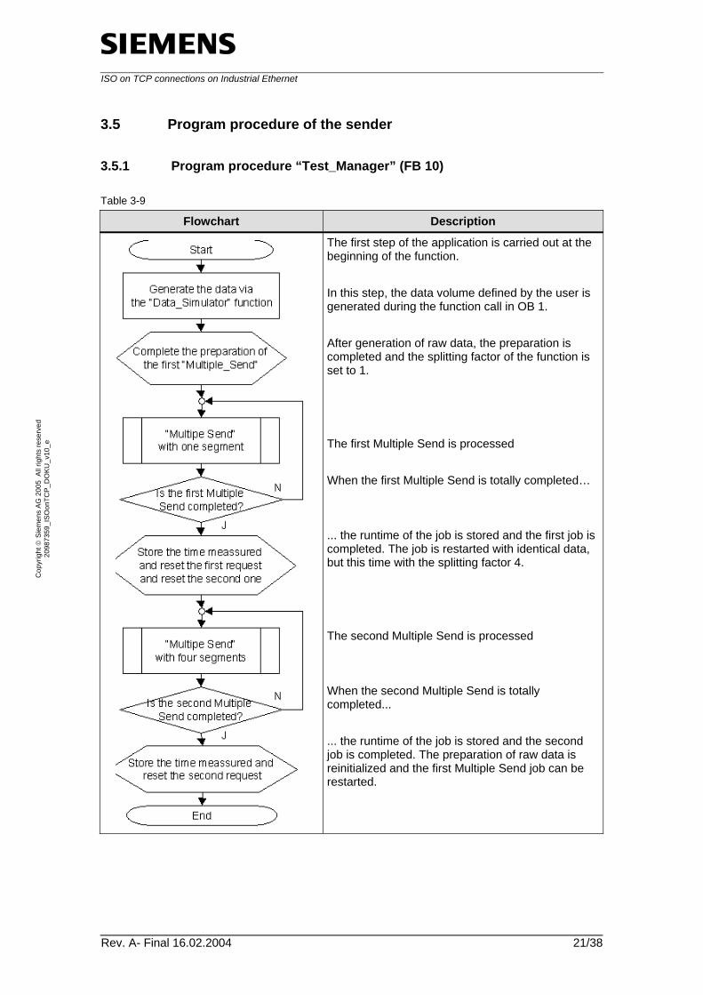
The first step of the application is carried out at the beginning of the function. In this step, the data volume defined by the user is generated during the function call in OB 1. After generation of raw data, the preparation is completed and the splitting factor of the function is set to 1. The first Multiple Send is processed When the first Multiple Send is totally completed… ... the runtime of the job is stored and the first job is completed. The job is restarted with identical data, but this time with the splitting factor 4. The second Multiple Send is processed When the second Multiple Send is totally completed... ... the runtime of the job is stored and the second job is completed. The preparation of raw data is reinitialized and the first Multiple Send job can be restarted.
ISO on TCP connections on Industrial Ethernet
Rev. A- Final 16.02.2004 22/38
Cop
yrig
ht ©
Sie
men
s AG
200
5 A
ll rig
hts
rese
rved
20
9873
59_I
SOon
TCP_
DO
KU_v
10_e
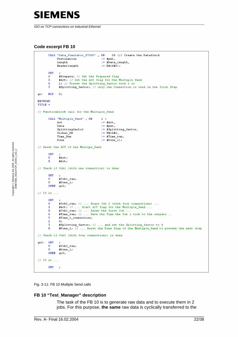
Code excerpt FB 10
Fig. 3-11: FB 10 Multiple Send calls
FB 10 “Test_Manager” description The task of the FB 10 is to generate raw data and to execute them in 2 jobs. For this purpose, the same raw data is cyclically transferred to the

ISO on TCP connections on Industrial Ethernet
Rev. A- Final 16.02.2004 23/38
Cop
yrig
ht ©
Sie
men
s AG
200
5 A
ll rig
hts
rese
rved
20
9873
59_I
SOon
TCP_
DO
KU_v
10_e
“Multiple_Send“ transfer function; once to be transferred via one connection and once via 4 connections. The runtimes of the both functions are returned to the calling block.
ISO on TCP connections on Industrial Ethernet
Rev. A- Final 16.02.2004 24/38
Cop
yrig
ht ©
Sie
men
s AG
200
5 A
ll rig
hts
rese
rved
20
9873
59_I
SOon
TCP_
DO
KU_v
10_e
3.5.2 Program procedure “Multiple_Send” (FB 1)
Table 3-10
Flowchart Description
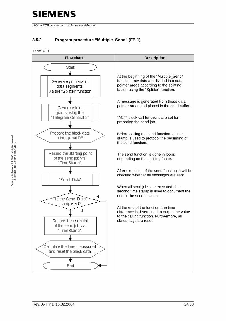
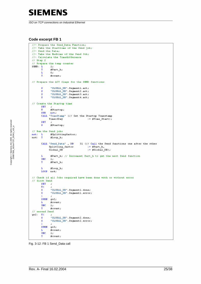
At the beginning of the “Multiple_Send“ function, raw data are divided into data pointer areas according to the splitting factor, using the “Splitter“ function. A message is generated from these data pointer areas and placed in the send buffer. “ACT“ block call functions are set for preparing the send job. Before calling the send function, a time stamp is used to protocol the beginning of the send function. The send function is done in loops depending on the splitting factor. After execution of the send function, it will be checked whether all messages are sent. When all send jobs are executed, the second time stamp is used to document the end of the send function. At the end of the function, the time difference is determined to output the value to the calling function. Furthermore, all status flags are reset.
ISO on TCP connections on Industrial Ethernet
Rev. A- Final 16.02.2004 25/38
Cop
yrig
ht ©
Sie
men
s AG
200
5 A
ll rig
hts
rese
rved
20
9873
59_I
SOon
TCP_
DO
KU_v
10_e
Code excerpt FB 1
Fig. 3-12: FB 1 Send_Data call
ISO on TCP connections on Industrial Ethernet
Rev. A- Final 16.02.2004 26/38
Cop
yrig
ht ©
Sie
men
s AG
200
5 A
ll rig
hts
rese
rved
20
9873
59_I
SOon
TCP_
DO
KU_v
10_e
FB 1 description The FB 1 “Multiple_Send” block forms the system environment for the send functions. In the first part of the block, if required, individual segments are created from the entire data volume and sent in portions using the “Splitter“ function. The second part of the block creates a message from the data fields which are then available. Apart from the pure data, it also contains a message header with further information for the receiving station. Furthermore, it also contains the number of the expected messages. The third and the last part of the block sequentially sends the data. A runtime is determined here to detect the duration of each job. After successful execution of all required jobs, the block is completed.
ISO on TCP connections on Industrial Ethernet
Rev. A- Final 16.02.2004 27/38
Cop
yrig
ht ©
Sie
men
s AG
200
5 A
ll rig
hts
rese
rved
20
9873
59_I
SOon
TCP_
DO
KU_v
10_e
3.5.3 Program procedure “Send_Data” (FB 31)
Table 3-11
Flowchart Description
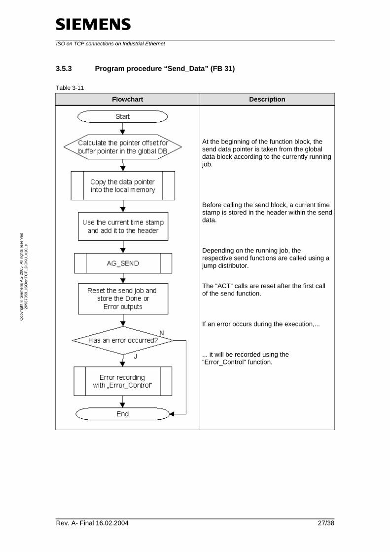
At the beginning of the function block, the send data pointer is taken from the global data block according to the currently running job. Before calling the send block, a current time stamp is stored in the header within the send data. Depending on the running job, the respective send functions are called using a jump distributor. The “ACT“ calls are reset after the first call of the send function. If an error occurs during the execution,... ... it will be recorded using the “Error_Control“ function.
ISO on TCP connections on Industrial Ethernet
Rev. A- Final 16.02.2004 28/38
Cop
yrig
ht ©
Sie
men
s AG
200
5 A
ll rig
hts
rese
rved
20
9873
59_I
SOon
TCP_
DO
KU_v
10_e
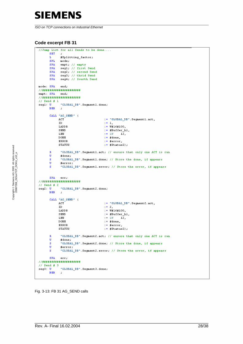
Code excerpt FB 31
Fig. 3-13: FB 31 AG_SEND calls

ISO on TCP connections on Industrial Ethernet
Rev. A- Final 16.02.2004 29/38
Cop
yrig
ht ©
Sie
men
s AG
200
5 A
ll rig
hts
rese
rved
20
9873
59_I
SOon
TCP_
DO
KU_v
10_e
FB 31 description The last block of the send path is the FB 31 “Send_Data“ block. The task of this block is to keep send jobs as encapsulated as possible in order to execute a sequential call in a closed way. The block takes data necessary for sending information from the global data block unless already predefined. After execution of the function, the function outputs are checked and saved. If errors occur during the function they are recorded using the “Error_Control“ function block.
3.6 Program procedure of the receiver
3.6.1 Program procedure “Multiple_Receive” (FB 2)
Table 3-12
Flowchart Description
At the beginning of the function block, all 4 possible receive functions are carried out successively. If an error occurs during the execution, it will be recorded correspondingly. If the number of the received message segments corresponds to the number of segments announced in the first message header... ... the “Combiner“ function block is started. In this function block, all message segments are combined to one block and stored in the target buffer. At the end of the block, all status flags are reset.
ISO on TCP connections on Industrial Ethernet
Rev. A- Final 16.02.2004 30/38
Cop
yrig
ht ©
Sie
men
s AG
200
5 A
ll rig
hts
rese
rved
20
9873
59_I
SOon
TCP_
DO
KU_v
10_e
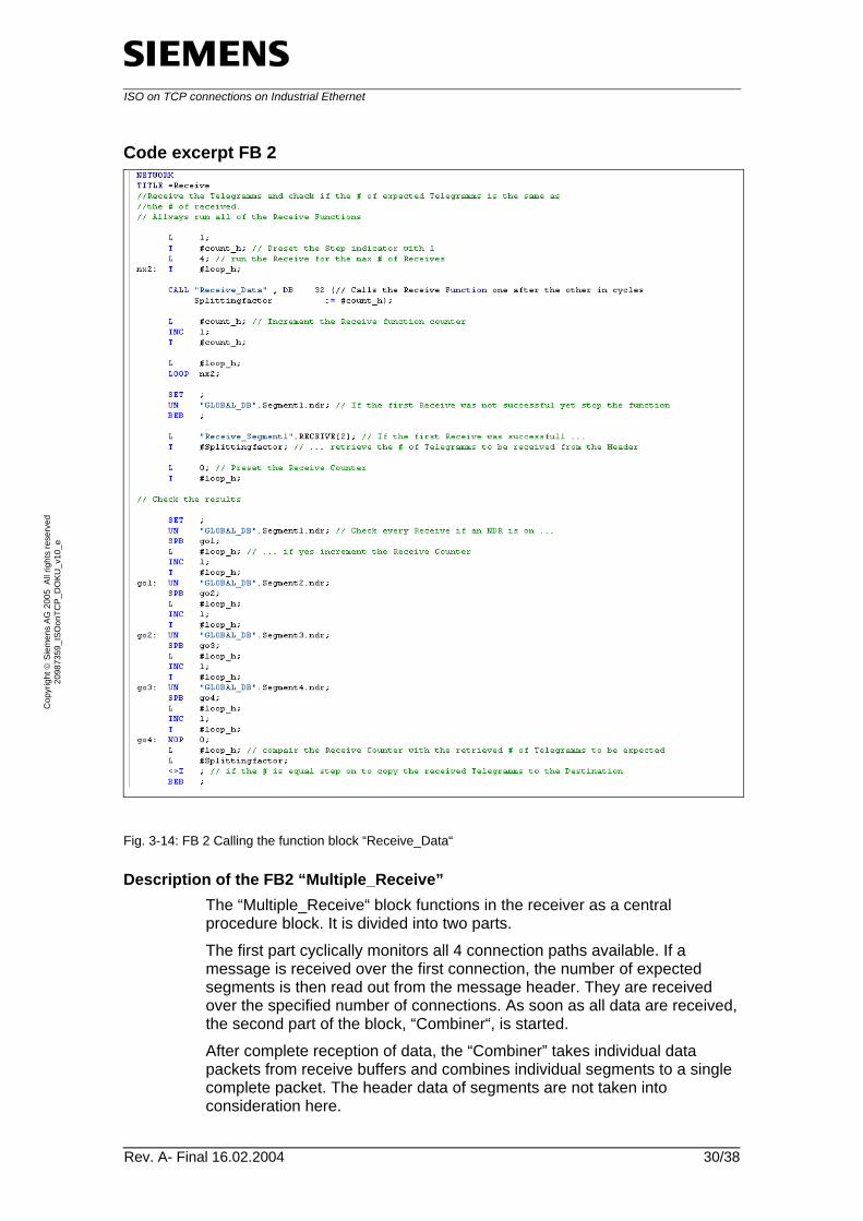
Code excerpt FB 2
Fig. 3-14: FB 2 Calling the function block “Receive_Data“
Description of the FB2 “Multiple_Receive” The “Multiple_Receive“ block functions in the receiver as a central procedure block. It is divided into two parts. The first part cyclically monitors all 4 connection paths available. If a message is received over the first connection, the number of expected segments is then read out from the message header. They are received over the specified number of connections. As soon as all data are received, the second part of the block, “Combiner“, is started. After complete reception of data, the “Combiner” takes individual data packets from receive buffers and combines individual segments to a single complete packet. The header data of segments are not taken into consideration here.
ISO on TCP connections on Industrial Ethernet
Rev. A- Final 16.02.2004 31/38
Cop
yrig
ht ©
Sie
men
s AG
200
5 A
ll rig
hts
rese
rved
20
9873
59_I
SOon
TCP_
DO
KU_v
10_e
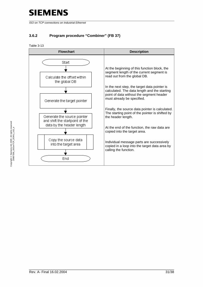
3.6.2 Program procedure “Combiner” (FB 37)
Table 3-13
Flowchart Description
At the beginning of this function block, the segment length of the current segment is read out from the global DB. In the next step, the target data pointer is calculated. The data length and the starting point of data without the segment header must already be specified. Finally, the source data pointer is calculated. The starting point of the pointer is shifted by the header length. At the end of the function, the raw data are copied into the target area. Individual message parts are successively copied in a loop into the target data area by calling the function.
ISO on TCP connections on Industrial Ethernet
Rev. A- Final 16.02.2004 32/38
Cop
yrig
ht ©
Sie
men
s AG
200
5 A
ll rig
hts
rese
rved
20
9873
59_I
SOon
TCP_
DO
KU_v
10_e
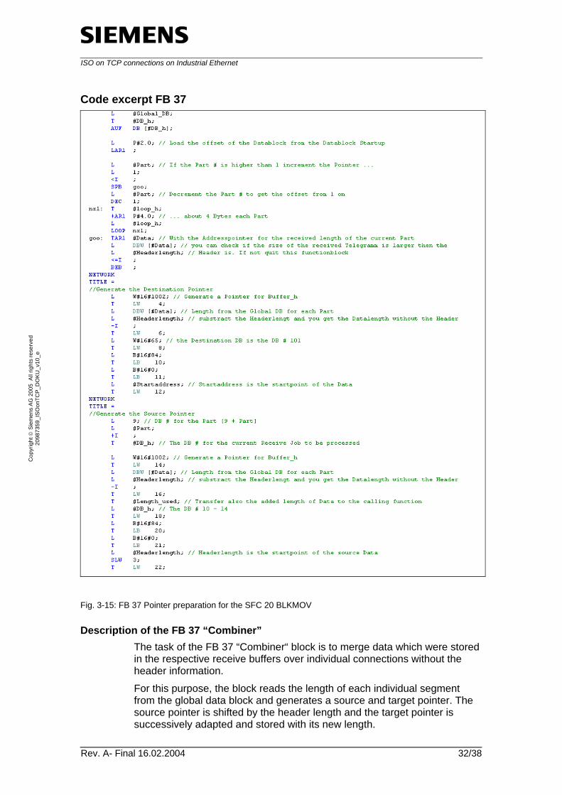
Code excerpt FB 37
Fig. 3-15: FB 37 Pointer preparation for the SFC 20 BLKMOV
Description of the FB 37 “Combiner” The task of the FB 37 “Combiner“ block is to merge data which were stored in the respective receive buffers over individual connections without the header information. For this purpose, the block reads the length of each individual segment from the global data block and generates a source and target pointer. The source pointer is shifted by the header length and the target pointer is successively adapted and stored with its new length.
ISO on TCP connections on Industrial Ethernet
Rev. A- Final 16.02.2004 33/38
Cop
yrig
ht ©
Sie
men
s AG
200
5 A
ll rig
hts
rese
rved
20
9873
59_I
SOon
TCP_
DO
KU_v
10_e
Because of data shifting, the processing is done synchronously to the cycle using the SFC 20 “BLKMOV”.
4 Determined Measured Values
The following section deals with measurements which were determined using the present application.
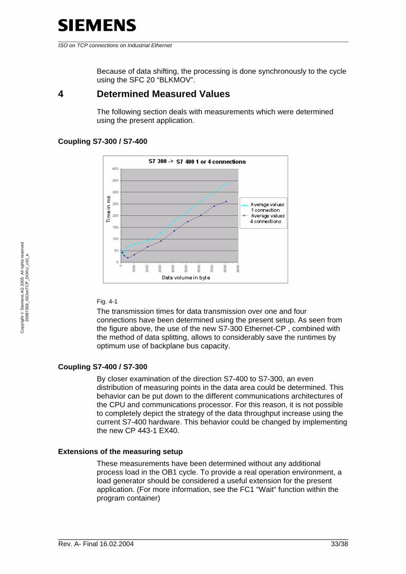
Coupling S7-300 / S7-400
Fig. 4-1 The transmission times for data transmission over one and four connections have been determined using the present setup. As seen from the figure above, the use of the new S7-300 Ethernet-CP , combined with the method of data splitting, allows to considerably save the runtimes by optimum use of backplane bus capacity.
Coupling S7-400 / S7-300 By closer examination of the direction S7-400 to S7-300, an even distribution of measuring points in the data area could be determined. This behavior can be put down to the different communications architectures of the CPU and communications processor. For this reason, it is not possible to completely depict the strategy of the data throughput increase using the current S7-400 hardware. This behavior could be changed by implementing the new CP 443-1 EX40.
Extensions of the measuring setup These measurements have been determined without any additional process load in the OB1 cycle. To provide a real operation environment, a load generator should be considered a useful extension for the present application. (For more information, see the FC1 “Wait“ function within the program container)
ISO on TCP connections on Industrial Ethernet
Rev. A- Final 16.02.2004 34/38
Cop
yrig
ht ©
Sie
men
s AG
200
5 A
ll rig
hts
rese
rved
20
9873
59_I
SOon
TCP_
DO
KU_v
10_e
5 Installation of Hardware and Software
5.1 Hardware configuration
The components of both controllers are available in chapter 2 ”Principle of the Automation Solution”.
Table 5-1: Hardware configuration
Step Focus Action
1 S7 Hardware Mount the S7 -400 into the prepared rack according to the installation guidelines.
2 S7 Hardware Mount the S7 -300 to the S7 -rack rail according to the installation guidelines.
3 Bus cabling Connect the MPI interfaces of both automating systems and the programming interface of the PG via a prepared Profibus cable.
4 Bus cabling Connect both Ethernet interfaces of the Ethernet CP using a cross-over cable or a stroke / switch.
5.2 Installation of the software
STEP7 At this point, we will not go further into the installation of STEP7. The installation takes place in the familiar Windows environment and is self-explanatory.
Installation of the STEP7 project To load the S7 project to controllers, proceed as follows:
Table 5-2
Step No. Action Note / Explanation
1 Open the Step 7 manager. 2 Extract the project via the menu File ->
Retrieve... Use the browser to search the SH_0457_Komm_ISOonTCP_CODE_v01_d/e.zip project and click OK to confirm.
ISO on TCP connections on Industrial Ethernet
Rev. A- Final 16.02.2004 35/38
Cop
yrig
ht ©
Sie
men
s AG
200
5 A
ll rig
hts
rese
rved
20
9873
59_I
SOon
TCP_
DO
KU_v
10_e
Step No. Action Note / Explanation
3 Select a directory into which the project files are to be extracted.
After extracting you are asked whether you wish to open the project with Step 7, acknowledge this query with Yes.
4 After opening the project you open the project tree of the project.
The project tree is located on the left side of the SIMATIC Manager and in the top line it displays the name of the project, in this case ISO_on_TCP.
5 Select the S7 –400 station first and then click
the icon to download the station.
This function is also available via Ctrl + L or the menu “Target system“ -> “Load“
6 Select now the S7 –300 station and again click
the icon to download the station.
This function is also available via Ctrl + L or the menu “Target system“ -> “Load“
Note If it is not possible to load the project directly, check whether Step 7 is able to establish a connection to the controller. In such a case, first load the hardware configuration into the controller to adapt the MPI address before loading the project into the CPU.
5.3 The core configurations of the application
The steps listed in the table below describe the configuration of the ISO on TCP connection using Netpro.
Table 5-3
Step No. Action Note / Explanation
1 Open the NETPRO network configuration within your project. This can be performed using the connection configuration named “Connections”, which is available in this project on CPU level, or
by clicking the button.
2 The following view should be displayed now: To have the configured connections displayed, select the respective CPU of the controller.
ISO on TCP connections on Industrial Ethernet
Rev. A- Final 16.02.2004 36/38
Cop
yrig
ht ©
Sie
men
s AG
200
5 A
ll rig
hts
rese
rved
20
9873
59_I
SOon
TCP_
DO
KU_v
10_e
Step No. Action Note / Explanation
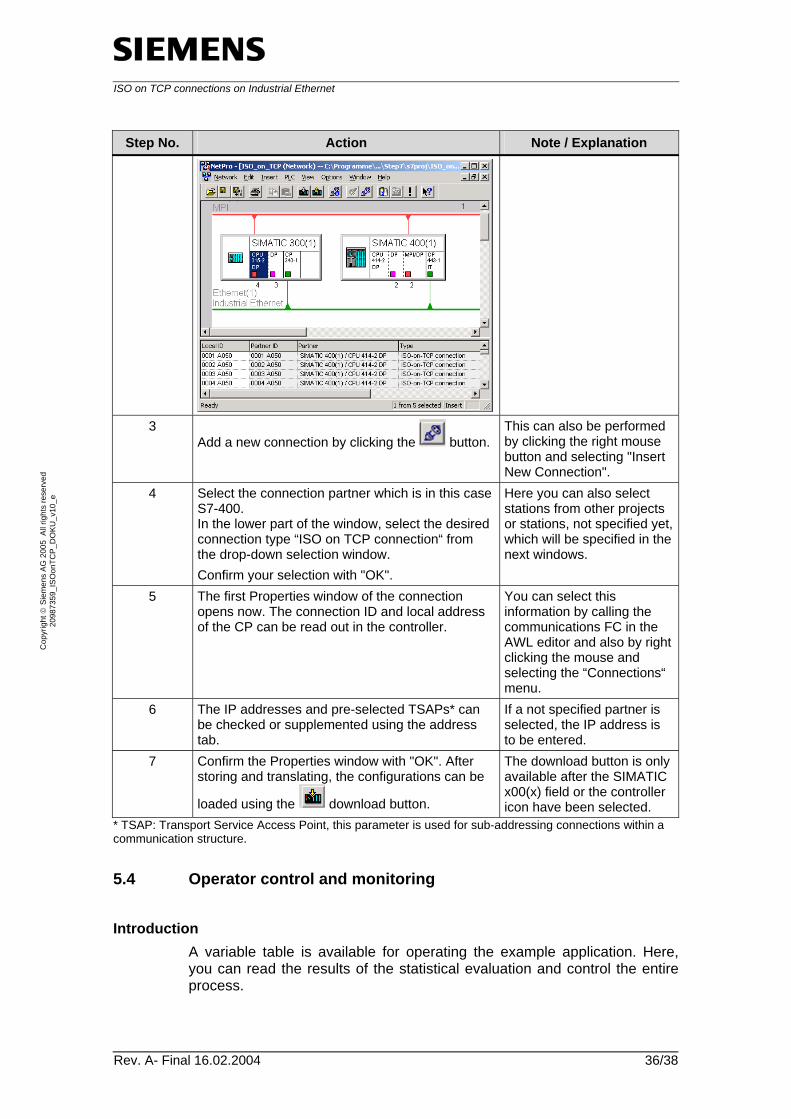
3 Add a new connection by clicking the button.
This can also be performed by clicking the right mouse button and selecting "Insert New Connection".
4 Select the connection partner which is in this case S7-400. In the lower part of the window, select the desired connection type “ISO on TCP connection“ from the drop-down selection window. Confirm your selection with "OK".
Here you can also select stations from other projects or stations, not specified yet, which will be specified in the next windows.
5 The first Properties window of the connection opens now. The connection ID and local address of the CP can be read out in the controller.
You can select this information by calling the communications FC in the AWL editor and also by right clicking the mouse and selecting the “Connections“ menu.
6 The IP addresses and pre-selected TSAPs* can be checked or supplemented using the address tab.
If a not specified partner is selected, the IP address is to be entered.
7 Confirm the Properties window with "OK". After storing and translating, the configurations can be
loaded using the download button.
The download button is only available after the SIMATIC x00(x) field or the controller icon have been selected.
* TSAP: Transport Service Access Point, this parameter is used for sub-addressing connections within a communication structure.
5.4 Operator control and monitoring
Introduction A variable table is available for operating the example application. Here, you can read the results of the statistical evaluation and control the entire process.
ISO on TCP connections on Industrial Ethernet
Rev. A- Final 16.02.2004 37/38
Cop
yrig
ht ©
Sie
men
s AG
200
5 A
ll rig
hts
rese
rved
20
9873
59_I
SOon
TCP_
DO
KU_v
10_e
Activating the variable table To start the variable table, perform the following steps.
Table 5-3
No. Description
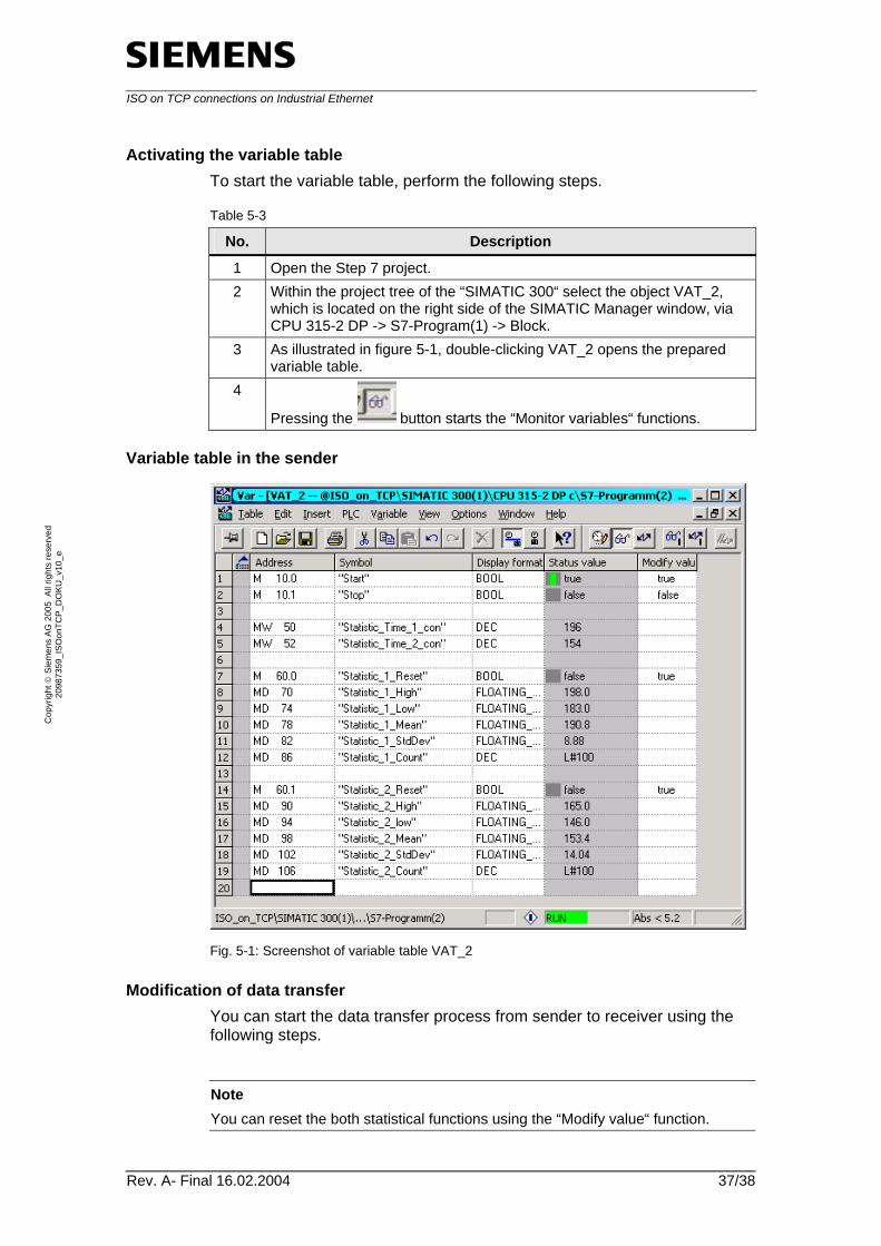
1 Open the Step 7 project. 2 Within the project tree of the “SIMATIC 300“ select the object VAT_2,
which is located on the right side of the SIMATIC Manager window, via CPU 315-2 DP -> S7-Program(1) -> Block.
3 As illustrated in figure 5-1, double-clicking VAT_2 opens the prepared variable table.
4
Pressing the button starts the “Monitor variables“ functions.
Variable table in the sender
Fig. 5-1: Screenshot of variable table VAT_2
Modification of data transfer You can start the data transfer process from sender to receiver using the following steps.
Note You can reset the both statistical functions using the “Modify value“ function.
ISO on TCP connections on Industrial Ethernet
Rev. A- Final 16.02.2004 38/38
Cop
yrig
ht ©
Sie
men
s AG
200
5 A
ll rig
hts
rese
rved
20
9873
59_I
SOon
TCP_
DO
KU_v
10_e
Table 5-4
Step No. Action Note
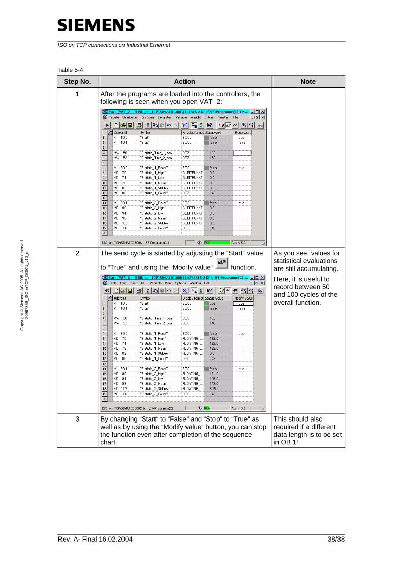
1 After the programs are loaded into the controllers, the following is seen when you open VAT_2:
2 The send cycle is started by adjusting the “Start“ value
to “True“ and using the “Modify value“ function.
As you see, values for statistical evaluations are still accumulating. Here, it is useful to record between 50 and 100 cycles of the overall function.
3 By changing “Start“ to “False“ and “Stop“ to “True“ as well as by using the “Modify value“ button, you can stop the function even after completion of the sequence chart.
This should also required if a different data length is to be set in OB 1!