application guidelines for 12-pulse operation of...
TRANSCRIPT
Application Technique
Application Guidelines for 12-Pulse Operation of PowerFlex 750-Series AC Drives

Application Guidelines for 12-Pulse Operation of PowerFlex 750-Series AC Drives
Important User InformationRead this document and the documents listed in the additional resources section about installation, configuration, and operation of this equipment before you install, configure, operate, or maintain this product. Users are required to familiarize themselves with installation and wiring instructions in addition to requirements of all applicable codes, laws, and standards.
Activities including installation, adjustments, putting into service, use, assembly, disassembly, and maintenance are required to be carried out by suitably trained personnel in accordance with applicable code of practice.
If this equipment is used in a manner not specified by the manufacturer, the protection provided by the equipment may be impaired.
In no event will Rockwell Automation, Inc. be responsible or liable for indirect or consequential damages resulting from the use or application of this equipment.
The examples and diagrams in this manual are included solely for illustrative purposes. Because of the many variables and requirements associated with any particular installation, Rockwell Automation, Inc. cannot assume responsibility or liability for actual use based on the examples and diagrams.
No patent liability is assumed by Rockwell Automation, Inc. with respect to use of information, circuits, equipment, or software described in this manual.
Reproduction of the contents of this manual, in whole or in part, without written permission of Rockwell Automation, Inc., is prohibited.
Throughout this manual, when necessary, we use notes to make you aware of safety considerations.
Labels may also be on or inside the equipment to provide specific precautions.
Allen-Bradley, PowerFlex, Rockwell Software, and Rockwell Automation are trademarks of Rockwell Automation, Inc.
Trademarks not belonging to Rockwell Automation are property of their respective companies.
WARNING: Identifies information about practices or circumstances that can cause an explosion in a hazardous environment, which may lead to personal injury or death, property damage, or economic loss.
ATTENTION: Identifies information about practices or circumstances that can lead to personal injury or death, property damage, or economic loss. Attentions help you identify a hazard, avoid a hazard, and recognize the consequence.
IMPORTANT Identifies information that is critical for successful application and understanding of the product.
SHOCK HAZARD: Labels may be on or inside the equipment, for example, a drive or motor, to alert people that dangerous voltage may be present.
BURN HAZARD: Labels may be on or inside the equipment, for example, a drive or motor, to alert people that surfaces may reach dangerous temperatures.
ARC FLASH HAZARD: Labels may be on or inside the equipment, for example, a motor control center, to alert people to potential Arc Flash. Arc Flash will cause severe injury or death. Wear proper Personal Protective Equipment (PPE). Follow ALL Regulatory requirements for safe work practices and for Personal Protective Equipment (PPE).
2 Rockwell Automation Publication 750-AT003A-EN-P - March 2014
Application Guidelines for 12-Pulse Operation of PowerFlex 750-Series AC Drives
Document Scope The scope of this document is to provide application guidelines for 12-pulse operation of PowerFlex 750-Series, frames 6…10, 400V…690V AC input drives. While several different transformer configurations are possible, only the commonly used delta-delta-wye transformer, which provides 30 degree phase shift between the two sets of secondary windings is addressed. The guidelines include sizing of the transformer and rectifier, grounding considerations, pre-charge, and circuit protection recommendations.
Drive Harmonics and Impact on Supply Network
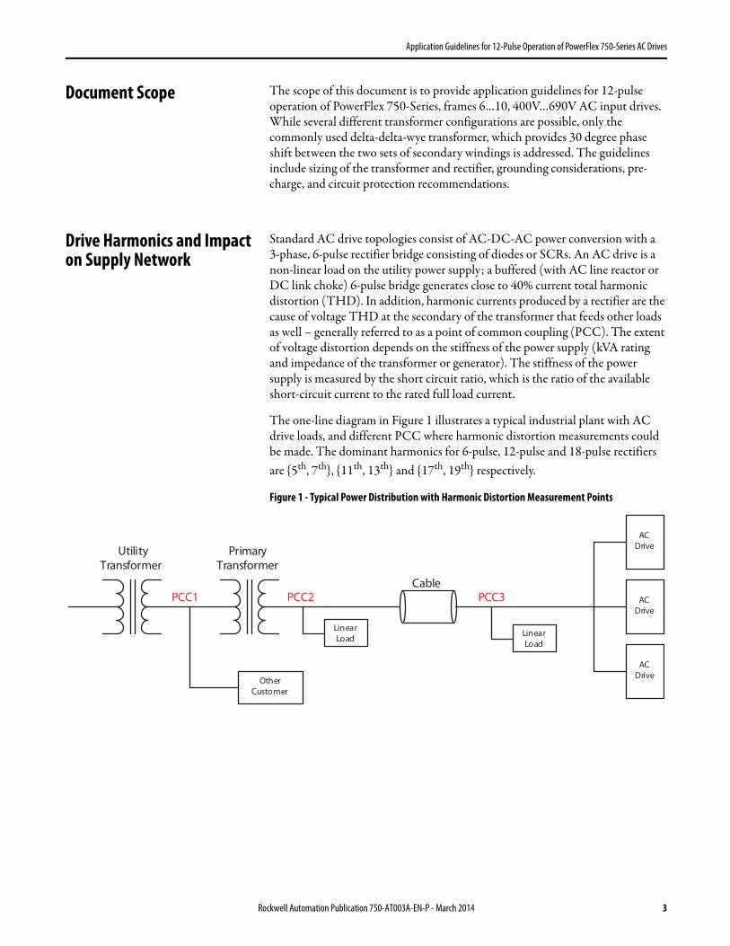
Standard AC drive topologies consist of AC-DC-AC power conversion with a3-phase, 6-pulse rectifier bridge consisting of diodes or SCRs. An AC drive is a non-linear load on the utility power supply; a buffered (with AC line reactor or DC link choke) 6-pulse bridge generates close to 40% current total harmonic distortion (THD). In addition, harmonic currents produced by a rectifier are the cause of voltage THD at the secondary of the transformer that feeds other loads as well – generally referred to as a point of common coupling (PCC). The extent of voltage distortion depends on the stiffness of the power supply (kVA rating and impedance of the transformer or generator). The stiffness of the power supply is measured by the short circuit ratio, which is the ratio of the available short-circuit current to the rated full load current.
The one-line diagram in Figure 1 illustrates a typical industrial plant with AC drive loads, and different PCC where harmonic distortion measurements could be made. The dominant harmonics for 6-pulse, 12-pulse and 18-pulse rectifiers are {5th, 7th}, {11th, 13th} and {17th, 19th} respectively.
Figure 1 - Typical Power Distribution with Harmonic Distortion Measurement Points
Other Customer
Linear Load
AC Drive
PCC3PCC2PCC1Cable
Primary Transformer
Utility Transformer
Linear Load
AC Drive
AC Drive
Rockwell Automation Publication 750-AT003A-EN-P - March 2014 3
Application Guidelines for 12-Pulse Operation of PowerFlex 750-Series AC Drives
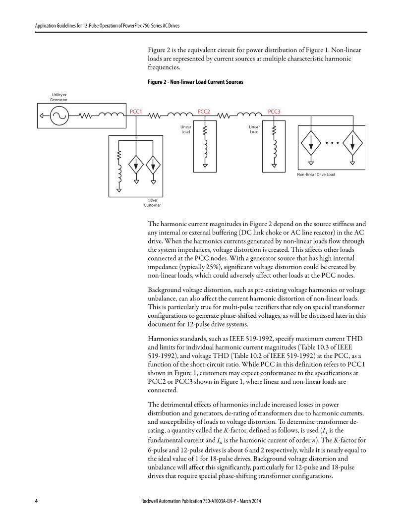
Figure 2 is the equivalent circuit for power distribution of Figure 1. Non-linear loads are represented by current sources at multiple characteristic harmonic frequencies.
Figure 2 - Non-linear Load Current Sources
The harmonic current magnitudes in Figure 2 depend on the source stiffness and any internal or external buffering (DC link choke or AC line reactor) in the AC drive. When the harmonics currents generated by non-linear loads flow through the system impedances, voltage distortion is created. This affects other loads connected at the PCC nodes. With a generator source that has high internal impedance (typically 25%), significant voltage distortion could be created by non-linear loads, which could adversely affect other loads at the PCC nodes.
Background voltage distortion, such as pre-existing voltage harmonics or voltage unbalance, can also affect the current harmonic distortion of non-linear loads. This is particularly true for multi-pulse rectifiers that rely on special transformer configurations to generate phase-shifted voltages, as will be discussed later in this document for 12-pulse drive systems.
Harmonics standards, such as IEEE 519-1992, specify maximum current THD and limits for individual harmonic current magnitudes (Table 10.3 of IEEE519-1992), and voltage THD (Table 10.2 of IEEE 519-1992) at the PCC, as a function of the short-circuit ratio. While PCC in this definition refers to PCC1 shown in Figure 1, customers may expect conformance to the specifications at PCC2 or PCC3 shown in Figure 1, where linear and non-linear loads are connected.
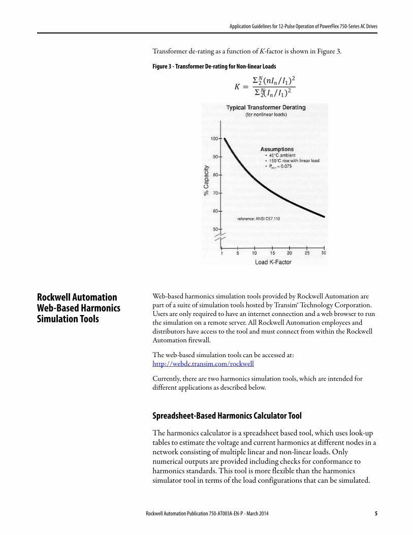
The detrimental effects of harmonics include increased losses in power distribution and generators, de-rating of transformers due to harmonic currents, and susceptibility of loads to voltage distortion. To determine transformer de-rating, a quantity called the K-factor, defined as follows, is used (I1 is the fundamental current and In is the harmonic current of order n). The K-factor for 6-pulse and 12-pulse drives is about 6 and 2 respectively, while it is nearly equal to the ideal value of 1 for 18-pulse drives. Background voltage distortion and unbalance will affect this significantly, particularly for 12-pulse and 18-pulse drives that require special phase-shifting transformer configurations.
…
PCC1 PCC2 PCC3
Other Customer
Linear Load
Linear Load
Non-linear Drive Load
Utility or Generator
4 Rockwell Automation Publication 750-AT003A-EN-P - March 2014
Application Guidelines for 12-Pulse Operation of PowerFlex 750-Series AC Drives
Transformer de-rating as a function of K-factor is shown in Figure 3.
Figure 3 - Transformer De-rating for Non-linear Loads
Rockwell AutomationWeb-Based Harmonics Simulation Tools
Web-based harmonics simulation tools provided by Rockwell Automation are part of a suite of simulation tools hosted by Transim® Technology Corporation. Users are only required to have an internet connection and a web browser to run the simulation on a remote server. All Rockwell Automation employees and distributors have access to the tool and must connect from within the Rockwell Automation firewall.
The web-based simulation tools can be accessed at:http://webdc.transim.com/rockwell
Currently, there are two harmonics simulation tools, which are intended for different applications as described below.
Spreadsheet-Based Harmonics Calculator Tool
The harmonics calculator is a spreadsheet based tool, which uses look-up tables to estimate the voltage and current harmonics at different nodes in a network consisting of multiple linear and non-linear loads. Only numerical outputs are provided including checks for conformance to harmonics standards. This tool is more flexible than the harmonics simulator tool in terms of the load configurations that can be simulated.
� = Σ (�I� I1/ )2�
2
Σ �2( I� I1/ )2
Rockwell Automation Publication 750-AT003A-EN-P - March 2014 5
Application Guidelines for 12-Pulse Operation of PowerFlex 750-Series AC Drives
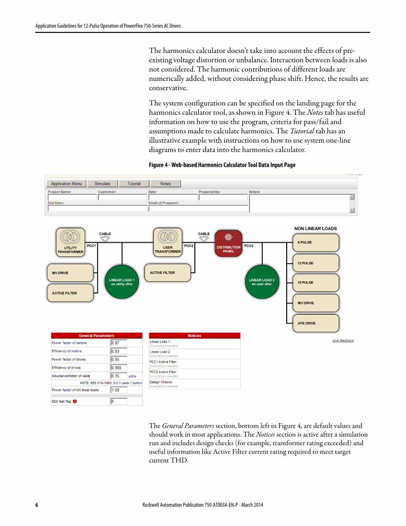
The harmonics calculator doesn’t take into account the effects of pre-existing voltage distortion or unbalance. Interaction between loads is also not considered. The harmonic contributions of different loads are numerically added, without considering phase shift. Hence, the results are conservative.
The system configuration can be specified on the landing page for the harmonics calculator tool, as shown in Figure 4. The Notes tab has useful information on how to use the program, criteria for pass/fail and assumptions made to calculate harmonics. The Tutorial tab has an illustrative example with instructions on how to use system one-line diagrams to enter data into the harmonics calculator.
Figure 4 - Web-based Harmonics Calculator Tool Data Input Page
The General Parameters section, bottom left in Figure 4, are default values and should work in most applications. The Notices section is active after a simulation run and includes design checks (for example, transformer rating exceeded) and useful information like Active Filter current rating required to meet target current THD.
6 Rockwell Automation Publication 750-AT003A-EN-P - March 2014
Application Guidelines for 12-Pulse Operation of PowerFlex 750-Series AC Drives
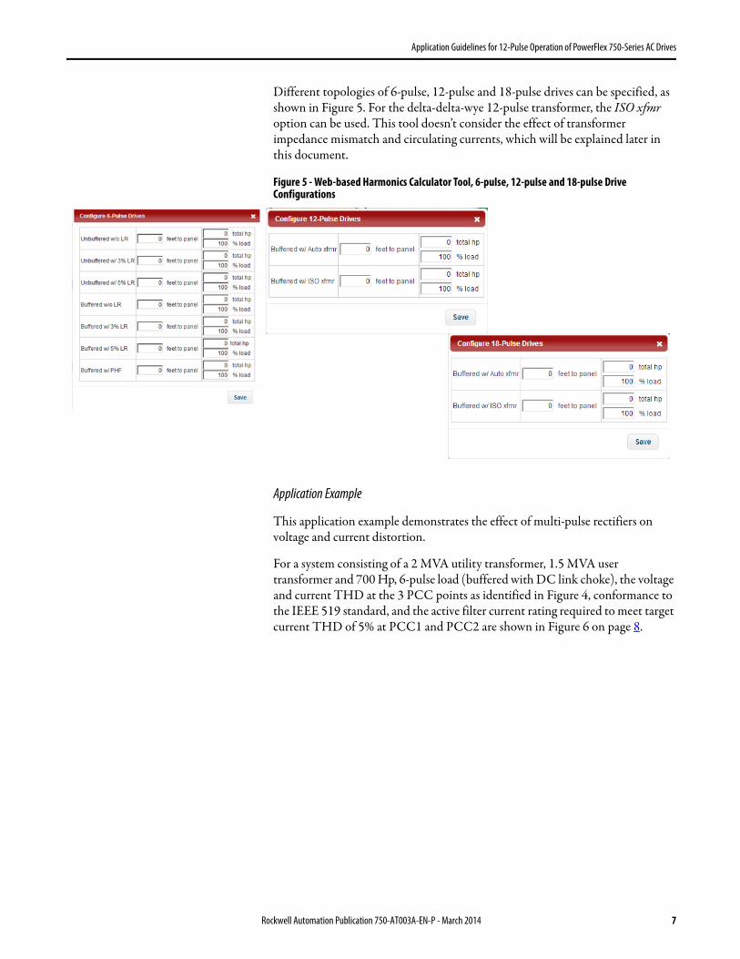
Different topologies of 6-pulse, 12-pulse and 18-pulse drives can be specified, as shown in Figure 5. For the delta-delta-wye 12-pulse transformer, the ISO xfmr option can be used. This tool doesn’t consider the effect of transformer impedance mismatch and circulating currents, which will be explained later in this document.
Figure 5 - Web-based Harmonics Calculator Tool, 6-pulse, 12-pulse and 18-pulse Drive Configurations
Application Example
This application example demonstrates the effect of multi-pulse rectifiers on voltage and current distortion.
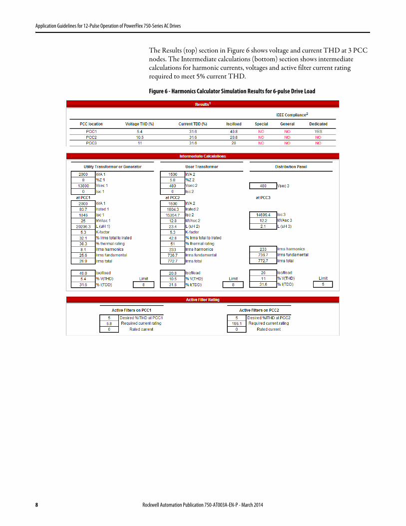
For a system consisting of a 2 MVA utility transformer, 1.5 MVA user transformer and 700 Hp, 6-pulse load (buffered with DC link choke), the voltage and current THD at the 3 PCC points as identified in Figure 4, conformance to the IEEE 519 standard, and the active filter current rating required to meet target current THD of 5% at PCC1 and PCC2 are shown in Figure 6 on page 8.
Rockwell Automation Publication 750-AT003A-EN-P - March 2014 7
Application Guidelines for 12-Pulse Operation of PowerFlex 750-Series AC Drives
The Results (top) section in Figure 6 shows voltage and current THD at 3 PCC nodes. The Intermediate calculations (bottom) section shows intermediate calculations for harmonic currents, voltages and active filter current rating required to meet 5% current THD.
Figure 6 - Harmonics Calculator Simulation Results for 6-pulse Drive Load
8 Rockwell Automation Publication 750-AT003A-EN-P - March 2014
Application Guidelines for 12-Pulse Operation of PowerFlex 750-Series AC Drives
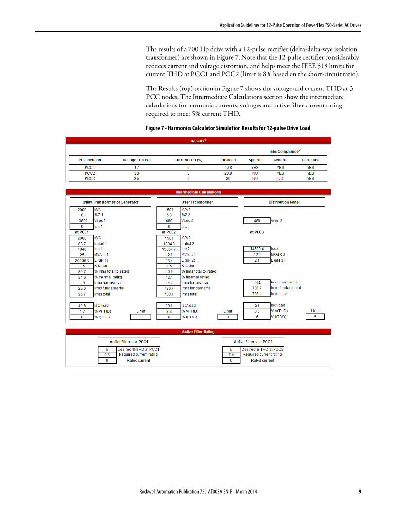
The results of a 700 Hp drive with a 12-pulse rectifier (delta-delta-wye isolation transformer) are shown in Figure 7. Note that the 12-pulse rectifier considerably reduces current and voltage distortion, and helps meet the IEEE 519 limits for current THD at PCC1 and PCC2 (limit is 8% based on the short-circuit ratio).
The Results (top) section in Figure 7 shows the voltage and current THD at 3 PCC nodes. The Intermediate Calculations section show the intermediate calculations for harmonic currents, voltages and active filter current rating required to meet 5% current THD.
Figure 7 - Harmonics Calculator Simulation Results for 12-pulse Drive Load
Rockwell Automation Publication 750-AT003A-EN-P - March 2014 9

Application Guidelines for 12-Pulse Operation of PowerFlex 750-Series AC Drives
Harmonics Circuit Simulator Tool
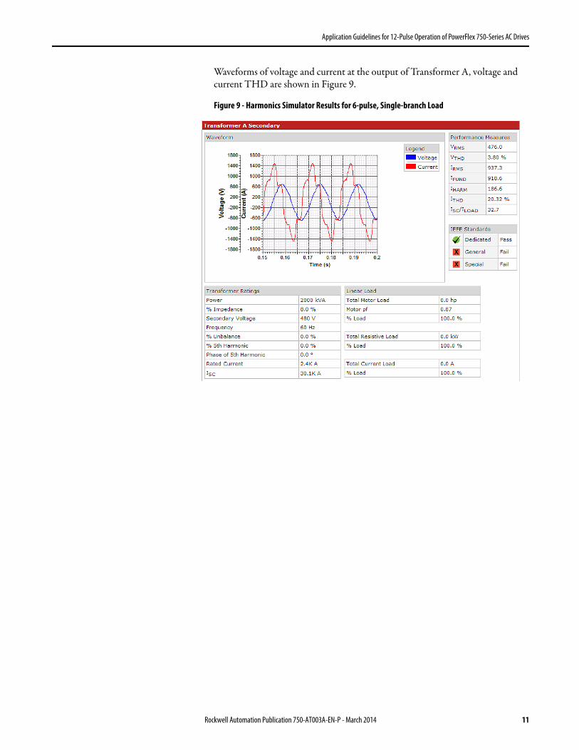
The harmonics simulator is a circuit simulation tool with one or two load branches. Each of the loads can be set to be of a specific type. Waveforms of voltage and current at different points of common coupling are generated along with numerical values for voltage and current THD, and checks for conformance to harmonics standards.
The one-line diagram of the system that is simulated is shown in Figure 8. On each branch, the load can only be of a certain type; currently only6-pulse or 18-pulse drives are supported on each individual transformer. Pre-existing distortion at the output of the utility transformer, 5th harmonic and voltage unbalance, can be set. Transformer B can be set to either delta-delta or delta-wye. To simulate a 12-pulse load, 6-pulse loads must be added on each transformer, and Transformer B must be set to delta-delta.
Figure 8 - Web-based Harmonics Circuit Simulation Tool Data Input Page
10 Rockwell Automation Publication 750-AT003A-EN-P - March 2014
Application Guidelines for 12-Pulse Operation of PowerFlex 750-Series AC Drives
Waveforms of voltage and current at the output of Transformer A, voltage and current THD are shown in Figure 9.
Figure 9 - Harmonics Simulator Results for 6-pulse, Single-branch Load
Rockwell Automation Publication 750-AT003A-EN-P - March 2014 11
Application Guidelines for 12-Pulse Operation of PowerFlex 750-Series AC Drives
12-pulse Drive Configurations
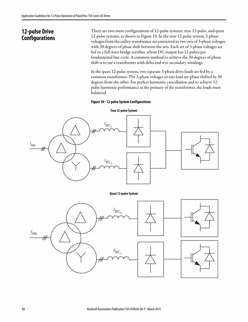
There are two main configurations of 12-pulse systems; true 12-pulse, and quasi 12-pulse systems, as shown in Figure 10. In the true 12-pulse system, 3-phase voltages from the utility transformer are converted to two sets of 3-phase voltages with 30 degrees of phase shift between the sets. Each set of 3-phase voltages are fed to a full wave bridge rectifier, whose DC output has 12 pulses per fundamental line cycle. A common method to achieve the 30 degrees of phase shift is to use a transformer with delta and wye secondary windings.
In the quasi 12-pulse system, two separate 3-phase drive loads are fed by a common transformer. The 3-phase voltages to one load are phase shifted by 30 degrees from the other. For perfect harmonic cancellation and to achieve 12-pulse harmonic performance at the primary of the transformer, the loads must balanced.
Figure 10 - 12-pulse System Configurations
IPRI
ISEC
ISECΔ
Y
True 12-pulse System
Quasi 12-pulse System
IPRI
ISEC
ISECΔ
Y
12 Rockwell Automation Publication 750-AT003A-EN-P - March 2014

Application Guidelines for 12-Pulse Operation of PowerFlex 750-Series AC Drives
Harmonic Cancellation in 12-pulse Drive Configurations
The predominant line current harmonics in a 3-phase, 6-pulse rectifier are the 5th and 7th harmonics of the fundamental. In a 12-pulse system, for both true12-pulse and balanced loads on quasi 12-pulse, the 5th and 7th harmonics are cancelled as demonstrated in the phasor diagram of Figure 11. Then, the dominant harmonics are the 11th and 13th, which are significantly lower in amplitude than the 5th and 7th. However, pre-existing voltage distortion and unbalance will significantly affect the performance of any 12-pulse system, as will be shown later.
Figure 11 - Cancellation of 5th and 7th Harmonics in a 12-pulse Drive
(a) (b)
Rockwell Automation Publication 750-AT003A-EN-P - March 2014 13

Application Guidelines for 12-Pulse Operation of PowerFlex 750-Series AC Drives
12-pulse Configurations for PowerFlex 750-Series Drives, Frames 6…10
For PowerFlex 750-Series drives, frames 6…10, several different 12-pulse configurations are possible, as shown in Figure 12, and Figure 13 and Figure 14 on page 15.
In the configuration shown in Figure 12, which is also similar to the configuration shown in Figure 13 and Figure 14, using the delta-delta-wye transformer and two rectifier bridges, a 12-pulse DC bus supply is created. Although shown specifically for frames 6…8, this configuration can be used to achieve true 12-pulse input for any combination of frames 6…10 DC input drives on the DC bus. With a diode rectifier front-end, integral pre-charge is required in the DC input drives, which is present on PowerFlex 750-Series frames 6…10 drives.
Quasi 12-pulse operation with AC input frames 6…10 drives can be achieved by distributing the load evenly between the delta and wye secondary windings.
Figure 12 - External Rectifier Bridges for PowerFlex 750-Series Frames 6…8 Drives with DC Input
External 6-pulse diode or SCR bridge rectifier
12-pulse DC Bus Supply
External 6-pulse diode or SCR bridge rectifier
Frame 6...8 PowerFlex 750-Series Drive with DC Input
14 Rockwell Automation Publication 750-AT003A-EN-P - March 2014
Application Guidelines for 12-Pulse Operation of PowerFlex 750-Series AC Drives
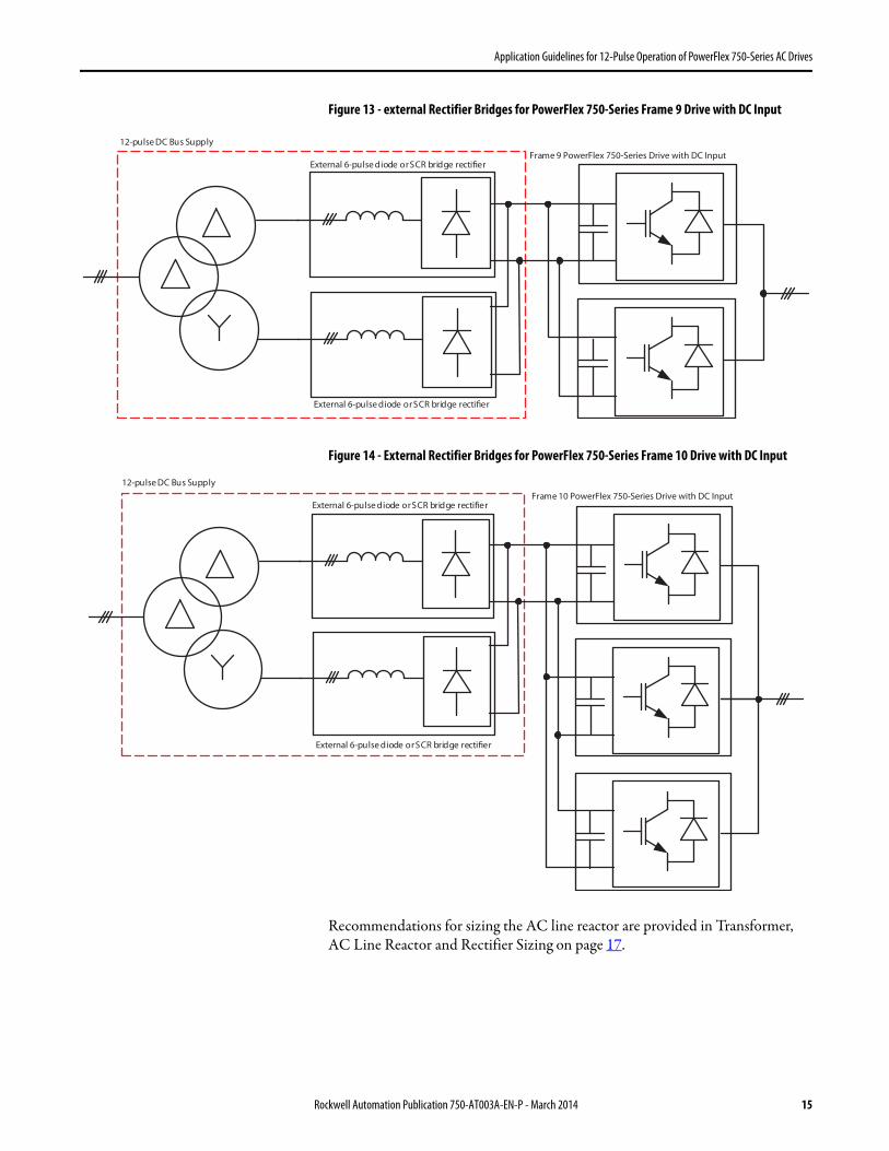
Figure 13 - external Rectifier Bridges for PowerFlex 750-Series Frame 9 Drive with DC Input
Figure 14 - External Rectifier Bridges for PowerFlex 750-Series Frame 10 Drive with DC Input
Recommendations for sizing the AC line reactor are provided in Transformer, AC Line Reactor and Rectifier Sizing on page 17.
External 6-pulse diode or SCR bridge rectifier
12-pulse DC Bus Supply
External 6-pulse diode or SCR bridge rectifier
Frame 9 PowerFlex 750-Series Drive with DC Input
External 6-pulse diode or SCR bridge rectifier
12-pulse DC Bus Supply
External 6-pulse diode or SCR bridge rectifier
Frame 10 PowerFlex 750-Series Drive with DC Input
Rockwell Automation Publication 750-AT003A-EN-P - March 2014 15
Application Guidelines for 12-Pulse Operation of PowerFlex 750-Series AC Drives
Grounding Considerations
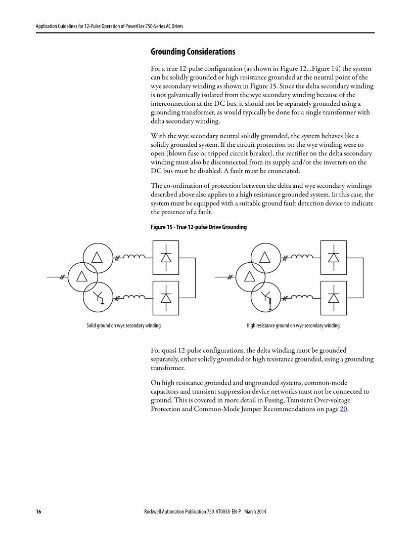
For a true 12-pulse configuration (as shown in Figure 12…Figure 14) the system can be solidly grounded or high resistance grounded at the neutral point of the wye secondary winding as shown in Figure 15. Since the delta secondary winding is not galvanically isolated from the wye secondary winding because of the interconnection at the DC bus, it should not be separately grounded using a grounding transformer, as would typically be done for a single transformer with delta secondary winding.
With the wye secondary neutral solidly grounded, the system behaves like a solidly grounded system. If the circuit protection on the wye winding were to open (blown fuse or tripped circuit breaker), the rectifier on the delta secondary winding must also be disconnected from its supply and/or the inverters on the DC bus must be disabled. A fault must be enunciated.
The co-ordination of protection between the delta and wye secondary windings described above also applies to a high resistance grounded system. In this case, the system must be equipped with a suitable ground fault detection device to indicate the presence of a fault.
Figure 15 - True 12-pulse Drive Grounding
For quasi 12-pulse configurations, the delta winding must be grounded separately, either solidly grounded or high resistance grounded, using a grounding transformer.
On high resistance grounded and ungrounded systems, common-mode capacitors and transient suppression device networks must not be connected to ground. This is covered in more detail in Fusing, Transient Over-voltage Protection and Common-Mode Jumper Recommendations on page 20.
Solid ground on wye secondary winding High resistance ground on wye secondary winding
16 Rockwell Automation Publication 750-AT003A-EN-P - March 2014
Application Guidelines for 12-Pulse Operation of PowerFlex 750-Series AC Drives
Pre-charge Considerations
For 12-pulse configurations that have diode bridge rectifiers, the DC input drives must have integral pre-charge. PowerFlex 750-Series, frames 6…10 drives with DC input all have integral pre-charge. On frames 6 and 7, the pre-charge circuit consists of a resistor in the +DC bus with SCR bypass and an anti-parallel diode for regenerative current flow. On frames 8…10, pre-charge resistors are placed on both +DC and –DC, with a Molded Case Switch (MCS) for bypass.
If SCR bridge rectifiers that have phase angle controlled pre-charge are used, then they must have independent means to synchronize to the phase shifted voltages. PowerFlex SCR Bus Supplies have this feature when two master units are used. See the PowerFlex SCR Bus Supply User Manual, publication 20S-UM001, for further information and particular parameter settings required for 12-pulse operation.
Transformer, AC Line Reactor and Rectifier Sizing
In this section, guidelines for sizing the transformer, AC line reactor and rectifier are provided. While the guidelines are based on certain assumptions for background voltage distortion (3% 5th harmonic voltage and 1% line unbalance), more severe background voltage distortion can result in higher continuous rating requirements for these components.
Rectifier and AC Line Reactor Sizing
For the true 12-pulse configuration of Figure 12, the causes of current unbalance between the two rectifier bridges are:
a. Fundamental voltage mismatch between delta and wye windings. The turns ratio between the delta and wye windings must ideally be .Since this is a non-integral ratio, the output voltages will not be perfectly balanced.
b. Impedance mismatch between the delta and wye windings due to differences in the number of turns and winding geometry. This asymmetry also presents different commutation inductances to the rectifier bridges.
c. Pre-existing 5th harmonic voltage has a different phase relationship with respect to the fundamental on the delta and wye secondaries.
d. Source voltage unbalance affects the delta and wye secondaries differently, due to the phase shift between them.
The extent of current unbalance can be reduced by adding an AC line reactor to each bridge. The impedance of the reactor minimizes the effect of impedance asymmetry between the delta and wye secondary windings, and helps to reduce the current unbalance caused by voltage unbalance or pre-existing voltage distortion. A line reactor sized at 3% impedance based on the rated voltage and current of one rectifier bridge is sufficient.
3:1
Rockwell Automation Publication 750-AT003A-EN-P - March 2014 17
Application Guidelines for 12-Pulse Operation of PowerFlex 750-Series AC Drives
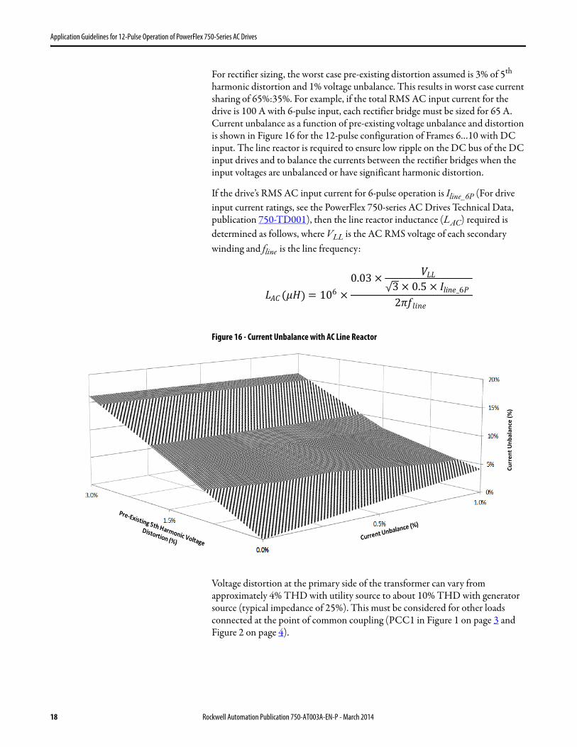
For rectifier sizing, the worst case pre-existing distortion assumed is 3% of 5th harmonic distortion and 1% voltage unbalance. This results in worst case current sharing of 65%:35%. For example, if the total RMS AC input current for the drive is 100 A with 6-pulse input, each rectifier bridge must be sized for 65 A. Current unbalance as a function of pre-existing voltage unbalance and distortion is shown in Figure 16 for the 12-pulse configuration of Frames 6…10 with DC input. The line reactor is required to ensure low ripple on the DC bus of the DC input drives and to balance the currents between the rectifier bridges when the input voltages are unbalanced or have significant harmonic distortion.
If the drive’s RMS AC input current for 6-pulse operation is Iline_6P (For drive input current ratings, see the PowerFlex 750-series AC Drives Technical Data, publication 750-TD001), then the line reactor inductance (LAC) required is determined as follows, where VLL is the AC RMS voltage of each secondary winding and fline is the line frequency:
Figure 16 - Current Unbalance with AC Line Reactor
Voltage distortion at the primary side of the transformer can vary from approximately 4% THD with utility source to about 10% THD with generator source (typical impedance of 25%). This must be considered for other loads connected at the point of common coupling (PCC1 in Figure 1 on page 3 and Figure 2 on page 4).
�AC (�� = 106 ×
0.03 �LL
3 × 0.5 × line_6
2�ƒ � ��
)
Cu
rre
nt
Un
ba
lan
ce (
%)
18 Rockwell Automation Publication 750-AT003A-EN-P - March 2014

Application Guidelines for 12-Pulse Operation of PowerFlex 750-Series AC Drives
Transformer Sizing and Specifications
Transformer kVA rating is based on worst case current unbalance between the delta and wye secondary windings.
Given that the drive’s input AC RMS current for 6-pulse input is Iline_6P and with the worst case unbalance of 65:35 between the two rectifier bridges, the total kVA rating of the transformer is determined as follows. The AC RMS voltage of each secondary winding is VLL. Since each secondary winding carries 6-pulse currents, an appropriate de-rating factor is applied:
Further, the open circuit voltage of the secondary windings must be matched.
The impedance of the transformer must be between 4…6%. The K-factor of the transformer must be greater than 6 to handle the harmonic currents.
The selection of PowerFlex SCR bus supplies for true 12-pulse operation of PowerFlex 750-Series, frames 6…10 drives, along with Bulletin 1321 line reactor catalog numbers and minimum transformer kVA is provided in PowerFlex SCR Bus Supply Selection Chart for 12-pulse Operation of PowerFlex 750-Series, Frames 6…10 Drives on page 21.
Electrostatic Shielding:
If the voltage on the primary side of the transformer is greater than twice the secondary voltage, an electrostatic shield between the primary and secondary windings is strongly recommended to prevent transients on the high voltage side from propagating to the secondary windings. An electrostatic shield reduces the capacitive coupling between the primary and secondary, and must be tied to ground. In addition, it is also recommended that the neutral of the wye secondary winding be solidly grounded. However, high resistance grounding with proper choice of resistance value to limit secondary transient voltage to ground is also acceptable. For quasi 12-pulse systems, the delta winding must be solidly grounded or high resistance grounded using a grounding transformer.
Transformer = 1.11
10003�LL 2 × 0.65 × line_6 ) = 1.43
1
10003�LLkVA ( line_6
Rockwell Automation Publication 750-AT003A-EN-P - March 2014 19

Application Guidelines for 12-Pulse Operation of PowerFlex 750-Series AC Drives
Fusing, Transient Over-voltage Protection and Common-Mode Jumper Recommendations
The recommended method for fusing and transient overvoltage protection is illustrated in Figure 17. The AC line fuses, typically high speed semiconductor fuses, should be integral to the rectifier bridge and are intended for short circuit protection of the rectifier power device. PowerFlex SCR bus supplies have AC fuses (on the 400 A and 600 A units, the fuses are on the AC line; on the 1000 A unit, the fuses are in series with each SCR device). If the rectifier bridge includes an integral capacitor bank, DC bus fuses should be placed after the capacitor bank and before the interconnection to the system DC bus, to prevent faults from cascading. PowerFlex SCR bus supplies do not have integral capacitor banks; however, the units rated at 400 A and 600 A have integral DC fuses, whereas the 1000 A unit does not have DC fuses.
Metal oxide varistors (MOV) are used for transient overvoltage protection and should be part of the rectifier power structure. PowerFlex SCR bus supplies have integral MOVs.
Fuses or circuit breakers should be used for branch circuit protection, with ratings in accordance with the NEC in the United States or local electrical codes as applicable. This is to protect each transformer secondary winding and the cabling to the rectifier bridge from overloads and short-circuits. The current rating to use for selection of the branch circuit protective device is 0.65Iline_6P, where a 65%:35% split is assumed for current sharing between the two rectifier bridges, and Iline_6P is the drive’s rated input RMS current for 6-pulse operation.
If the secondary wye winding of the transformer is not solidly grounded, then any common mode capacitor networks on the AC line or DC bus (on both the rectifier bridges and the drives on the DC bus), and the MOVs must be disconnected from ground. For instructions on how to disconnect the MOVs and common mode capacitors, see the PowerFlex SCR Bus Supply User Manual, publication 20S-UM001, and the PowerFlex 750-Series AC Drives Installation Instructions, publication 750-IN001.
To achieve compliance with the EMC directive of IEC, the AC system must be solidly grounded at the wye secondary and the common mode capacitor networks must be connected to ground.
Figure 17 - 12-pulse Drive Branch Circuit Protection, Fusing and Transient Overvoltage Protection
Branch CircuitProtection
FuseFuse
MOV
FuseFuse
MOV
20 Rockwell Automation Publication 750-AT003A-EN-P - March 2014

Application Guidelines for 12-Pulse Operation of PowerFlex 750-Series AC Drives
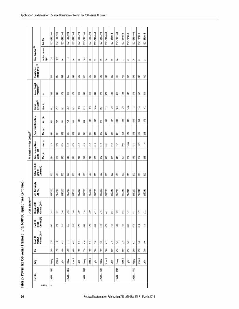
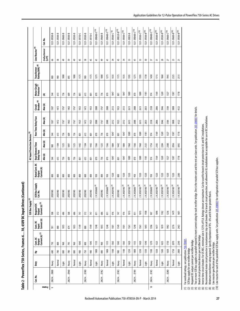
PowerFlex SCR Bus Supply Selection Chart for 12-pulse Operation of PowerFlex 750-Series, Frames 6…10 Drives
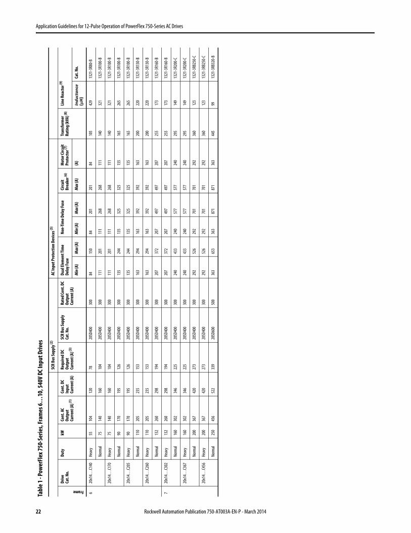
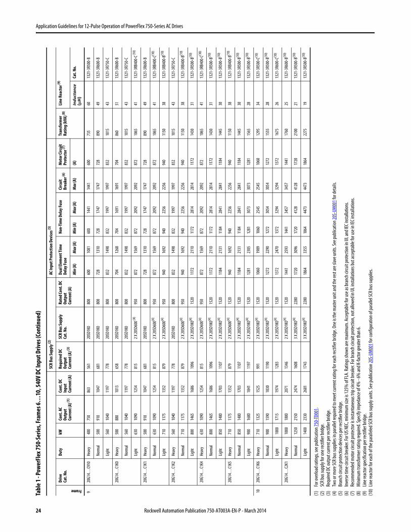
Table 1…Table 4, beginning on page 22, provide the PowerFlex SCR bus supply and Bulletin 1321 line reactor catalog numbers, ratings for input branch circuit protection devices, and the kVA rating of the delta-delta-wye transformer for use with PowerFlex 750-Series, frame 6…10 drives.
The ratings specified in the tables are based on maximum voltage unbalance of 1% and 5th harmonic distortion of 3%, which is a conservative estimate of worst case power quality. However, if the voltage unbalance or harmonic distortion exceeds these values, then the current unbalance between the rectifier bridges will exceed the assumptions made in Table 1…Table 4, requiring higher current rating for the rectifier, transformer and branch circuit protective device. Please contact Rockwell Automation Technical Support for assistance in sizing the components.
Rockwell Automation Publication 750-AT003A-EN-P - March 2014 21
Application Guidelines for 12-Pulse Operation of PowerFlex 750-Series AC Drives
Tabl
e 1 - P
ower
Flex
750-
Serie
s, Fr
ames
6…10
, 540
V DC
Inpu
t Driv
es
SCR
Bus S
uppl
y (2)
AC In
put P
rote
ctio
n De
vice
s (5)
Frame
Drive
Cat.
No.
Duty
kW
Cont
. AC
Outp
ut
Curre
nt (A
) (1)
Cont
. DC
Inpu
t Cu
rrent
(A)
Requ
ired
DC
Outp
ut
Curre
nt (A
) (3)
SCR
Bus S
uppl
yCa
t. No
.Ra
ted C
ont.
DC
Outp
ut
Curre
nt (A
)
Dual
Elem
ent T
ime
Dela
y Fus
eNo
n-Ti
me D
elay
Fuse
Circ
uit
Brea
ker (6
)M
otor
Circ
uit
Prot
ecto
r (7)
Tran
sform
er
Ratin
g (k
VA) (8
)Lin
e Rea
ctor
(9)
Min
(A)
Max
(A)
Min
(A)
Max
(A)
Max
(A)
(A)
Inductance
(µH
)Ca
t. No
.
620
x14…
C140
Heav
y55
104
120
7820
SD40
030
084
150
8420
120
184
105
429
1321
-3R8
0-B
Norm
al75
140
160
104
20SD
400
300
111
201
111
268
268
111
140
321
1321
-3R1
00-B
20x1
4…C1
70He
avy
7514
016
010
420
SD40
030
011
120
111
126
826
811
114
032
113
21-3
R100
-B
Norm
al90
170
195
126
20SD
400
300
135
244
135
325
325
135
165
265
1321
-3R1
00-B
20x1
4…C2
05He
avy
9017
019
512
620
SD40
030
013
524
413
532
532
513
516
526
513
21-3
R100
-B
Norm
al11
020
523
515
320
SD40
030
016
329
416
339
239
216
320
022
013
21-3
R130
-B
20x1
4…C2
60He
avy
110
205
235
153
20SD
400
300
163
294
163
392
392
163
200
220
1321
-3R1
30-B
Norm
al13
226
029
819
420
SD40
030
020
737
220
749
749
720
725
517
313
21-3
R160
-B
720
x14…
C302
Heav
y13
226
029
819
420
SD40
030
020
737
220
749
749
720
725
517
313
21-3
R160
-B
Norm
al16
030
234
622
520
SD40
030
024
043
324
057
757
724
029
514
913
21-3
R200
-C
20x1
4…C3
67He
avy
160
302
346
225
20SD
400
300
240
433
240
577
577
240
295
149
1321
-3R2
00-C
Norm
al20
036
742
027
320
SD40
030
029
252
629
270
170
129
236
012
313
21-3
RB25
0-C
20x1
4…C4
56He
avy
200
367
420
273
20SD
400
300
292
526
292
701
701
292
360
123
1321
-3RB
250-
C
Norm
al25
045
652
233
920
SD60
050
036
365
336
387
187
136
344
599
1321
-3RB
320-
B
22 Rockwell Automation Publication 750-AT003A-EN-P - March 2014

Application Guidelines for 12-Pulse Operation of PowerFlex 750-Series AC Drives
820
G14…
C460
Heav
y20
038
544
328
820
SD40
030
030
955
630
974
174
130
938
011
613
21-3
RB25
0-B
Norm
al25
046
052
934
420
SD60
050
037
066
537
088
788
737
045
597
1321
-3RB
320-
B
Light
315
540
621
404
20SD
600
500
434
781
434
1041
1041
434
530
8313
21-3
RB40
0-C
20G1
4…C5
40He
avy
250
456
525
341
20SD
600
500
366
658
366
878
878
366
450
9813
21-3
RB32
0-B
Norm
al31
554
062
140
420
SD60
050
043
378
043
310
3910
3943
353
083
1321
-3RB
400-
C
Light
315
585
673
437
20SD
600
500
470
845
470
1127
1127
470
575
7613
21-3
RB40
0-B
20G1
4…C5
67He
avy
250
472
543
353
20SD
600
500
379
682
379
909
909
379
465
9513
21-3
RB32
0-B
Norm
al31
556
765
242
420
SD60
050
045
581
945
510
9210
9245
555
579
1321
-3RB
400-
B
Light
355
612
704
458
20SD
600
500
491
883
491
1178
1178
491
600
7313
21-3
RB40
0-B
20G1
4…C6
50He
avy
315
540
621
404
20SD
600
500
433
780
433
1039
1039
433
530
8313
21-3
RB40
0-C
Norm
al35
565
074
848
620
SD60
050
052
093
652
012
4812
4852
063
569
1321
-3RB
400-
B
Light
400
750
863
561
20SD
1K0
800
600
1081
600
1441
1441
600
735
6013
21-3
R500
-B
20G1
4…C7
50He
avy
315
585
673
437
20SD
600
500
469
844
469
1125
1125
469
575
7613
21-3
RB40
0-B
Norm
al40
075
086
356
120
SD1K
080
060
010
8160
014
4114
4160
073
560
1321
-3R5
00-B
Light
450
796
916
595
20SD
1K0
800
637
1147
637
1529
1529
637
780
5613
21-3
R500
-B
20G1
4…C7
70He
avy
355
642
739
480
20SD
600
500
515
927
515
1236
1236
515
630
7013
21-3
RB40
0-B
Norm
al40
077
088
657
620
SD1K
080
061
611
0961
614
7814
7861
675
558
1321
-3R5
00-B
Light
450
832
957
622
20SD
1K0
800
665
1198
665
1597
1597
665
815
5413
21-3
R600
-C
Tabl
e 1 - P
ower
Flex
750-
Serie
s, Fr
ames
6…10
, 540
V DC
Inpu
t Driv
es (C
ontin
ued)
SCR
Bus S
uppl
y (2)
AC In
put P
rote
ctio
n De
vice
s (5)
Frame
Drive
Cat.
No.
Duty
kW
Cont
. AC
Outp
ut
Curre
nt (A
) (1)
Cont
. DC
Inpu
t Cu
rrent
(A)
Requ
ired
DC
Outp
ut
Curre
nt (A
) (3)
SCR
Bus S
uppl
yCa
t. No
.Ra
ted C
ont.
DC
Outp
ut
Curre
nt (A
)
Dual
Elem
ent T
ime
Dela
y Fus
eNo
n-Ti
me D
elay
Fuse
Circ
uit
Brea
ker (6
)M
otor
Circ
uit
Prot
ecto
r (7)
Tran
sform
er
Ratin
g (k
VA) (8
)Lin
e Rea
ctor
(9)
Min
(A)
Max
(A)
Min
(A)
Max
(A)
Max
(A)
(A)
Inductance
(µH
)Ca
t. No
.
Rockwell Automation Publication 750-AT003A-EN-P - March 2014 23
Application Guidelines for 12-Pulse Operation of PowerFlex 750-Series AC Drives
920
G14…
C910
Heav
y40
075
086
356
120
SD1K
080
060
010
8160
014
4114
4160
073
560
1321
-3R5
00-B
Norm
al50
091
010
4768
120
SD1K
080
072
813
1072
817
4717
4772
889
049
1321
-3R6
00-B
Light
560
1040
1197
778
20SD
1K0
800
832
1498
832
1997
1997
832
1015
4313
21-3
R750
-C
20G1
4…C1
K0He
avy
500
880
1013
658
20SD
1K0
800
704
1268
704
1691
1691
704
860
5113
21-3
R600
-B
Norm
al56
010
4011
9777
820
SD1K
080
083
214
9883
219
9719
9783
210
1543
1321
-3R7
50-C
Light
630
1090
1254
815
2 X 20
SD60
0 (4)
950
872
1569
872
2092
2092
872
1065
4113
21-3
RB40
0-C (1
0)
20G1
4…C1
K1He
avy
500
910
1047
681
20SD
1K0
800
728
1310
728
1747
1747
728
890
4913
21-3
R600
-B
Norm
al63
010
9012
5481
52 X
20SD
600(4
)95
087
215
6987
220
9220
9287
210
6541
1321
-3RB
400-
C(10)
Light
710
1175
1352
879
2 X 20
SD60
0(4)
950
940
1692
940
2256
2256
940
1150
3813
21-3
RB40
0-B(1
0)
20G1
4…C1
K2He
avy
560
1040
1197
778
20SD
1K0
800
832
1498
832
1997
1997
832
1015
4313
21-3
R750
-C
Norm
al71
011
7513
5287
92 X
20SD
600(4
)95
094
016
9294
022
5622
5694
011
5038
1321
-3RB
400-
B(10)
Light
800
1465
1686
1096
2 X 20
SD1K
0(4)
1520
1172
2110
1172
2814
2814
1172
1430
3113
21-3
R500
-B(1
0)
20G1
4…C1
K4He
avy
630
1090
1254
815
2 X 20
SD60
0(4)
950
872
1569
872
2092
2092
872
1065
4113
21-3
RB40
0-C(1
0)
Norm
al80
014
6516
8610
962 X
20SD
1K0(4
)15
2011
7221
1011
7228
1428
1411
7214
3031
1321
-3R5
00-B
(10)
Light
850
1480
1703
1107
2 X 20
SD1K
0(4)
1520
1184
2131
1184
2841
2841
1184
1445
3013
21-3
R500
-B(1
0)
20G1
4…C1
K5He
avy
710
1175
1352
879
2 X 20
SD60
0(4)
1520
940
1692
940
2256
2256
940
1150
3813
21-3
RB40
0-B(1
0)
Norm
al85
014
8017
0311
072 X
20SD
1K0(4
)15
2011
8421
3111
8428
4128
4111
8414
4530
1321
-3R5
00-B
(10)
Light
900
1600
1841
1197
2 X 20
SD1K
0(4)
1520
1281
2305
1281
3073
3073
1281
1565
2813
21-3
R500
-B(1
0)
1020
G14…
C1K6
Heav
y71
013
2515
2599
12 X
20SD
1K0(4
)15
2010
6019
0910
6025
4525
4510
6012
9534
1321
-3R5
00-C
(10)
Norm
al90
015
9018
3011
902 X
20SD
1K0(4
)15
2012
7222
9012
7230
5430
5412
7215
5528
1321
-3R5
00-B
(10)
Light
1000
1715
1974
1283
2 X 20
SD1K
0(4)
1520
1372
2470
1372
3294
3294
1372
1675
2613
21-3
R600
-C(1
0)
20G1
4…C2
K1He
avy
1000
1800
2071
1346
2 X 20
SD1K
0(4)
1520
1441
2593
1441
3457
3457
1441
1760
2513
21-3
R600
-B(1
0)
Norm
al12
5021
5024
7416
083 X
20SD
1K0(4
)22
8017
2030
9617
2041
2841
2817
2021
0021
1321
-3R5
00-B
(10)
Light
1400
2330
2681
1743
3 X 20
SD1K
0(4)
2280
1864
3355
1864
4473
4473
1864
2275
1913
21-3
R500
-B(1
0)
(1)
For o
verlo
ad ra
tings
, see
publi
catio
n 750
-TD0
01.
(2)
SCR b
us su
pply
for o
ne re
ctifie
r brid
ge.
(3)
Requ
ired D
C out
put c
urre
nt pe
r rec
tifier
bridg
e.(4
)Tw
o or m
ore S
CR bu
s sup
plies
in pa
ralle
l requ
ired t
o mee
t cur
rent
ratin
g for
each
recti
fier b
ridge
. One
is th
e mas
ter u
nit an
d the
rest
are s
lave u
nits.
See p
ublic
ation
20S-
UM00
1 for
deta
ils.
(5)
Bran
ch ci
rcuit
prot
ectio
n dev
ices p
er re
ctifie
r brid
ge.
(6)
Inve
rse ti
me c
ircuit
brea
ker. F
or U
S NEC
, mini
mum
size
is 12
5% of
FLA.
Ratin
gs sh
own a
re m
axim
um. A
ccept
able
for u
se as
bran
ch ci
rcuit p
rote
ction
in U
L and
IEC i
nsta
llatio
ns.
(7)
Reco
mm
ende
d mot
or ci
rcuit
prot
ecto
r is in
stant
aneo
us tr
ip cir
cuit
brea
ker. F
or br
anch
circu
it pr
otec
tion,
not a
llowe
d in U
L ins
talla
tions
but a
ccep
tabl
e for
use i
n IEC
insta
llatio
ns.
(8)
Min
imum
tran
sform
er ra
ting r
equir
ed. S
pecif
y im
peda
nce o
f 4%
- 6%
and K
-facto
r gre
ater
than
6.(9
)Lin
e rea
ctor s
pecif
icatio
n per
recti
fier b
ridge
.(1
0)Lin
e rea
ctor f
or ea
ch of
the p
arall
eled S
CR bu
s sup
ply u
nits.
See p
ublic
ation
20S-
UM00
1 for
conf
igura
tion o
f par
allel
SCR b
us su
pplie
s.
Tabl
e 1 - P
ower
Flex
750-
Serie
s, Fr
ames
6…10
, 540
V DC
Inpu
t Driv
es (C
ontin
ued)
SCR
Bus S
uppl
y (2)
AC In
put P
rote
ctio
n De
vice
s (5)
Frame
Drive
Cat.
No.
Duty
kW
Cont
. AC
Outp
ut
Curre
nt (A
) (1)
Cont
. DC
Inpu
t Cu
rrent
(A)
Requ
ired
DC
Outp
ut
Curre
nt (A
) (3)
SCR
Bus S
uppl
yCa
t. No
.Ra
ted C
ont.
DC
Outp
ut
Curre
nt (A
)
Dual
Elem
ent T
ime
Dela
y Fus
eNo
n-Ti
me D
elay
Fuse
Circ
uit
Brea
ker (6
)M
otor
Circ
uit
Prot
ecto
r (7)
Tran
sform
er
Ratin
g (k
VA) (8
)Lin
e Rea
ctor
(9)
Min
(A)
Max
(A)
Min
(A)
Max
(A)
Max
(A)
(A)
Inductance
(µH
)Ca
t. No
.
24 Rockwell Automation Publication 750-AT003A-EN-P - March 2014

Application Guidelines for 12-Pulse Operation of PowerFlex 750-Series AC Drives
Tabl
e 2 - P
ower
Flex
750-
Serie
s, Fr
ames
6…10
, 650
V DC
Inpu
t Driv
es
SCR
Bus S
uppl
y (2)
AC In
put P
rote
ctio
n De
vice
s (5)
Frame
Cat.
No.
Duty
HpCo
nt. A
C Ou
tput
Cu
rrent
(A) (1
)
Cont
. DC
Inpu
t Cu
rrent
(A)
Requ
ired
DC
Outp
ut
Curre
nt (A
) (3)
SCR
Bus S
uppl
y Ca
t. No
.Ra
ted C
ont.
DC
Outp
ut
Curre
nt (A
)
Dual
Elem
ent T
ime
Dela
y Fus
eNo
n-Ti
me D
elay
Fuse
Circ
uit
Brea
ker (6
)M
otor
Circ
uit
Prot
ecto
r (7)
Tran
sform
er
Ratin
g (k
VA) (8
)Lin
e Rea
ctor
(9)
Min
(A)
Max
(A)
Min
(A)
Max
(A)
Max
(A)
(A)
Inductance
(µ
H)
Cat.
No.
620
x14…
D125
Heav
y75
9610
568
20SD
400
300
7313
273
176
176
7311
049
013
21-3
R55-
B
Norm
al10
012
513
789
20SD
400
300
9517
295
229
229
9514
037
613
21-3
R80-
B
20x1
4…D1
56He
avy
100
125
137
8920
SD40
030
095
172
9522
922
995
140
376
1321
-3R8
0-B
Norm
al12
515
617
111
120
SD40
030
011
921
411
928
628
611
917
530
113
21-3
R100
-B
20x1
4…D1
86He
avy
125
156
171
111
20SD
400
300
119
214
119
286
286
119
175
301
1321
-3R1
00-B
Norm
al15
018
620
413
320
SD40
030
014
225
514
234
034
014
221
025
313
21-3
R130
-C
20x1
4…D2
48He
avy
150
186
204
133
20SD
400
300
142
255
142
340
340
142
210
253
1321
-3R1
30-C
Norm
al20
024
827
217
720
SD40
030
018
934
018
945
445
418
928
018
913
21-3
R160
-B
720
x14…
D302
Heav
y20
024
827
217
720
SD40
030
018
934
018
945
445
418
928
018
913
21-3
R160
-B
Norm
al25
030
233
121
520
SD40
030
023
041
523
055
355
323
034
015
613
21-3
R200
-B
20x1
4…D3
61He
avy
250
302
331
215
20SD
400
300
230
415
230
553
553
230
340
156
1321
-3R2
00-B
Norm
al30
036
139
625
720
SD40
030
027
549
627
566
166
127
540
513
013
21-3
RB25
0-C
20x1
4…D4
15He
avy
300
361
396
257
20SD
400
300
275
496
275
661
661
275
405
130
1321
-3RB
250-
C
Norm
al35
041
545
529
620
SD40
030
031
757
031
776
076
031
746
511
313
21-3
RB25
0-B
Rockwell Automation Publication 750-AT003A-EN-P - March 2014 25
Application Guidelines for 12-Pulse Operation of PowerFlex 750-Series AC Drives
820
G14…
D430
Heav
y30
037
040
726
520
SD40
030
028
451
028
468
168
128
441
512
613
21-3
RB25
0-C
Norm
al35
043
047
330
720
SD60
050
033
059
433
079
279
233
048
510
913
21-3
RB25
0-B
Light
400
485
533
346
20SD
600
500
372
670
372
893
893
372
545
9613
21-3
RB32
0-B
20G1
4…D4
85He
avy
350
414
455
296
20SD
400
300
318
572
318
762
762
318
465
113
1321
-3RB
250-
B
Norm
al40
048
553
334
620
SD60
050
037
267
037
289
389
337
254
596
1321
-3RB
320-
B
Light
450
545
599
389
20SD
600
500
418
752
418
1002
1002
418
615
8613
21-3
RB32
0-B
20G1
4…D5
45He
avy
350
454
499
324
20SD
600
500
348
626
348
835
835
348
510
103
1321
-3RB
320-
C
Norm
al45
054
559
938
920
SD60
050
041
875
241
810
0210
0241
861
586
1321
-3RB
320-
B
Light
500
590
649
422
20SD
600
500
453
815
453
1086
1086
453
665
7913
21-3
RB40
0-B
20G1
4…D6
17He
avy
400
485
533
346
20SD
600
500
372
670
372
893
893
372
545
9613
21-3
RB32
0-B
Norm
al50
061
767
844
120
SD60
050
047
385
147
311
3511
3547
369
576
1321
-3RB
400-
B
Light
600
710
781
508
20SD
1K0
800
544
980
544
1307
1307
544
800
6613
21-3
R500
-B
20G1
4…D7
10He
avy
450
545
599
389
20SD
600
500
418
752
418
1002
1002
418
615
8613
21-3
RB32
0-B
Norm
al60
071
078
150
820
SD1K
080
050
190
250
112
0312
0350
173
571
1321
-3R4
00-B
Light
650
765
841
547
20SD
1K0
800
587
1056
587
1408
1408
587
860
6113
21-3
R500
-B
20G1
4…D7
40He
avy
500
617
678
441
20SD
600
800
473
851
473
1135
1135
473
695
7613
21-3
RB40
0-B
Norm
al65
074
081
452
920
SD1K
080
056
710
2156
713
6113
6156
783
063
1321
-3R5
00-B
Light
700
800
880
572
20SD
1K0
800
613
1104
613
1472
1472
613
900
5813
21-3
R500
-B
Tabl
e 2 - P
ower
Flex
750-
Serie
s, Fr
ames
6…10
, 650
V DC
Inpu
t Driv
es (C
ontin
ued)
SCR
Bus S
uppl
y (2)
AC In
put P
rote
ctio
n De
vice
s (5)
Frame
Cat.
No.
Duty
HpCo
nt. A
C Ou
tput
Cu
rrent
(A) (1
)
Cont
. DC
Inpu
t Cu
rrent
(A)
Requ
ired
DC
Outp
ut
Curre
nt (A
) (3)
SCR
Bus S
uppl
y Ca
t. No
.Ra
ted C
ont.
DC
Outp
ut
Curre
nt (A
)
Dual
Elem
ent T
ime
Dela
y Fus
eNo
n-Ti
me D
elay
Fuse
Circ
uit
Brea
ker (6
)M
otor
Circ
uit
Prot
ecto
r (7)
Tran
sform
er
Ratin
g (k
VA) (8
)Lin
e Rea
ctor
(9)
Min
(A)
Max
(A)
Min
(A)
Max
(A)
Max
(A)
(A)
Inductance
(µ
H)
Cat.
No.
26 Rockwell Automation Publication 750-AT003A-EN-P - March 2014
Application Guidelines for 12-Pulse Operation of PowerFlex 750-Series AC Drives
920
G14…
D800
Heav
y60
071
078
150
820
SD1K
080
054
498
054
413
0713
0754
480
066
1321
-3R5
00-B
Norm
al70
080
088
057
220
SD1K
080
061
311
0461
314
7214
7261
390
058
1321
-3R5
00-B
Light
800
960
1055
686
20SD
1K0
800
736
1325
736
1767
1767
736
1080
4913
21-3
R600
-B
20G1
4…D9
60He
avy
700
795
874
568
20SD
1K0
800
609
1097
609
1463
1463
609
895
5913
21-3
R500
-B
Norm
al80
096
010
5568
620
SD1K
080
073
613
2573
617
6717
6773
610
8049
1321
-3R5
00-B
Light
900
1045
1149
747
20SD
1K0
800
801
1442
801
1923
1923
801
1175
4513
21-3
R750
-C
20G1
4…D1
K0He
avy
750
800
880
572
20SD
1K0
800
613
1104
613
1472
1472
613
900
5813
21-3
R500
-B
Norm
al90
010
4511
4974
720
SD1K
080
080
114
4280
119
2319
2380
111
7545
1321
-3R7
50-C
Light
1000
1135
1248
811
2 X 20
SD60
0 (4)
950
870
1566
870
2088
2088
870
1275
4113
21-3
RB40
0-C(1
0)
20G1
4…D1
K2He
avy
800
960
1055
686
20SD
1K0
800
736
1325
736
1767
1767
736
1080
4913
21-3
R600
-B
Norm
al10
0011
3512
4881
12 X
20SD
600 (4
)95
087
015
6687
020
8820
8887
012
7541
1321
-3RB
400-
C(10)
Light
1100
1365
1501
976
2 X 20
SD1K
0 (4)
1520
1047
1884
1047
2512
2512
1047
1535
3413
21-3
R500
-C 10
)
20G1
4…D1
K3He
avy
900
1045
1149
747
20SD
1K0
800
801
1442
801
1923
1923
801
1175
4513
21-3
RB32
0-B(1
0)
Norm
al11
0013
6515
0197
62 X
20SD
1K0 (4
)15
2010
4718
8410
4725
1225
1210
4715
3534
1321
-3R5
00-C
(10)
Light
1250
1420
1561
1015
2 X 20
SD1K
0 (4)
1520
1089
1960
1089
2613
2613
1089
1595
3313
21-3
R850
-B
20G1
4…D1
K4He
avy
1000
1135
1248
811
2 X 20
SD60
0 (4)
950
870
1566
870
2088
2088
870
1275
4113
21-3
RB40
0-C(1
0)
Norm
al12
5014
2015
6110
152 X
20SD
1K0 (4
)15
2010
8919
6010
8926
1326
1310
8915
9533
1321
-3R5
00-C
(10)
Light
1350
1540
1693
1100
2 X 20
SD1K
0 (4)
1520
1181
2125
1181
2833
2833
1181
1730
3013
21-3
R500
-B(1
0)
1020
G14…
D1K5
Heav
y11
0012
7013
9690
72 X
20SD
600 (4
)95
097
417
5497
423
3823
3897
414
3037
1321
-3RB
400-
C(10)
Norm
al13
5015
2516
7710
902 X
20SD
1K0 (4
)15
2011
6921
0511
6928
0628
0611
6917
1531
1321
-3R5
00-B
(10)
Light
1500
1655
1819
1182
2 X 20
SD1K
0 (4)
1520
1269
2284
1269
3046
3046
1269
1860
2813
21-3
R500
-B(1
0)
20G1
4…D2
K0He
avy
1650
1730
1902
1236
2 X 20
SD1K
0 (4)
1520
1327
2388
1327
3184
3184
1327
1945
2713
21-3
R600
-C(1
0)
Norm
al17
5020
7022
7614
792 X
20SD
1K0 (4
)15
2015
8728
5615
8738
0838
0815
8723
2523
1321
-3R6
00-B
(10)
Light
2000
2240
2463
1601
3 X 20
SD1K
0 (4)
2280
1718
3092
1718
4122
4122
1718
2515
2113
21-3
R500
-B(1
0)
(1)
For o
verlo
ad ra
tings
, see
publi
catio
n 750
-TD0
01.
(2)
SCR b
us su
pply
for o
ne re
ctifie
r brid
ge.
(3)
Requ
ired D
C out
put c
urre
nt pe
r rec
tifier
bridg
e.(4
)Tw
o or m
ore S
CR bu
s sup
plies
in pa
ralle
l requ
ired t
o mee
t cur
rent
ratin
g for
each
recti
fier b
ridge
. One
is th
e mas
ter u
nit an
d the
rest
are s
lave u
nits.
See p
ublic
ation
20S-
UM00
1 for
deta
ils.
(5)
Bran
ch ci
rcuit
prot
ectio
n dev
ices p
er re
ctifie
r brid
ge.
(6)
Inve
rse ti
me c
ircuit
brea
ker. F
or U
S NEC
, mini
mum
size
is 12
5% of
FLA.
Ratin
gs sh
own a
re m
axim
um. C
an be
used
for b
ranc
h circ
uit pr
otec
tion i
n UL a
nd IE
C ins
talla
tions
.(7
)Re
com
men
ded m
otor
circu
it pr
otec
tor is
insta
ntan
eous
trip
circu
it br
eake
r. For
bran
ch ci
rcuit
prot
ectio
n, no
t allo
wed i
n UL i
nsta
llatio
ns bu
t acc
epta
ble f
or us
e in I
EC in
stalla
tions
.(8
)M
inim
um tr
ansfo
rmer
ratin
g req
uired
. Spe
cify i
mpe
danc
e of 4
% -
6% an
d K-fa
ctor g
reat
er th
an 6.
(9)
Line r
eacto
r spe
cifica
tion p
er re
ctifie
r brid
ge.
(10)
Line r
eacto
r for
each
of th
e par
allele
d SCR
bus s
uppl
y unit
s. Se
e pub
licat
ion 20
S-UM
001 f
or co
nfigu
ratio
n of p
arall
el SC
R bus
supp
lies.
Tabl
e 2 - P
ower
Flex
750-
Serie
s, Fr
ames
6…10
, 650
V DC
Inpu
t Driv
es (C
ontin
ued)
SCR
Bus S
uppl
y (2)
AC In
put P
rote
ctio
n De
vice
s (5)
Frame
Cat.
No.
Duty
HpCo
nt. A
C Ou
tput
Cu
rrent
(A) (1
)
Cont
. DC
Inpu
t Cu
rrent
(A)
Requ
ired
DC
Outp
ut
Curre
nt (A
) (3)
SCR
Bus S
uppl
y Ca
t. No
.Ra
ted C
ont.
DC
Outp
ut
Curre
nt (A
)
Dual
Elem
ent T
ime
Dela
y Fus
eNo
n-Ti
me D
elay
Fuse
Circ
uit
Brea
ker (6
)M
otor
Circ
uit
Prot
ecto
r (7)
Tran
sform
er
Ratin
g (k
VA) (8
)Lin
e Rea
ctor
(9)
Min
(A)
Max
(A)
Min
(A)
Max
(A)
Max
(A)
(A)
Inductance
(µ
H)
Cat.
No.
Rockwell Automation Publication 750-AT003A-EN-P - March 2014 27

Application Guidelines for 12-Pulse Operation of PowerFlex 750-Series AC Drives
Tabl
e 3 - P
ower
Flex
750-
Serie
s, Fr
ames
6…10
, 810
V DC
Inpu
t Driv
es
SCR
Bus S
uppl
y (2)
AC In
put P
rote
ctio
n De
vice
s (5)
Frame
Cat.
No.
Duty
HpCo
nt. A
C Ou
tput
Cu
rrent
(A) (1
)
Cont
. DC
Inpu
t Cu
rrent
(A)
Requ
ired
DC
Outp
ut
Curre
nt (A
) (3)
SCR
Bus S
uppl
yCa
t. No
.Ra
ted
DC
Outp
ut
Curre
nt (A
)
Dual
Elem
ent T
ime
Dela
y Fus
eNo
n-Ti
me D
elay
Fuse
Circ
uit
Brea
ker (6
)M
otor
Circ
uit
Prot
ecto
4 (7)
Tran
sform
er
Ratin
g (k
VA) (8
)Li
ne R
eact
or (9
)
Min
(A)
Max
(A)
Min
(A)
Max
(A)
Max
(A)
(A)
Inductance
(µ
H)
Cat.
No.
620
x14…
E099
Heav
y75
7784
5520
SF1K
080
059
106
5914
114
159
110
763
1321
-3R5
5-C
Norm
al10
099
108
7020
SF1K
080
075
136
7518
118
175
140
593
1321
-3R5
5-B
20x1
4…E1
25He
avy
100
9910
870
20SF
1K0
800
7513
675
181
181
7514
059
313
21-3
R55-
B
Norm
al12
512
513
789
20SF
1K0
800
9517
295
229
229
9517
547
013
21-3
R80-
C
20x1
4…E1
44He
avy
125
125
137
8920
SF1K
080
095
172
9522
922
995
175
470
1321
-3R8
0-C
Norm
al15
014
415
810
220
SF1K
080
011
019
811
026
426
411
020
540
813
21-3
R80-
B
720
x14…
E192
Heav
y15
014
415
810
220
SF1K
080
011
019
811
026
426
411
020
540
813
21-3
R80-
B
Norm
al20
019
221
013
720
SF1K
080
014
626
414
635
235
214
627
030
613
21-3
R130
-C
20x1
4…E2
42He
avy
200
192
210
137
20SF
1K0
800
146
264
146
352
352
146
270
306
1321
-3R1
30-C
Norm
al25
024
226
517
220
SF1K
080
018
533
218
544
344
318
534
024
313
21-3
RB16
0-C
20x1
4…E2
89He
avy
250
242
265
172
20SF
1K0
800
185
332
185
443
443
185
340
243
1321
-3RB
160-
C
Norm
al30
028
931
620
620
SF1K
080
022
039
722
052
952
922
040
520
313
21-3
R200
-C
820
G14…
E295
Heav
y25
027
230
019
520
SF1K
080
020
937
620
950
150
120
938
521
513
21-3
RB16
0-C
Norm
al30
029
532
521
120
SF1K
080
024
243
624
258
158
124
244
518
513
21-3
RB20
0-C
Light
350
355
391
254
20SF
1K0
800
272
490
272
653
653
272
500
165
1321
-3RB
250-
C
20G1
4…E3
55He
avy
300
295
325
211
20SF
1K0
800
226
407
226
542
542
226
415
198
1321
-3R2
00-C
Norm
al35
035
539
125
420
SF1K
080
027
249
027
265
365
327
250
016
513
21-3
RB25
0-C
Light
400
395
436
283
20SF
1K0
800
303
546
303
727
727
303
555
148
1321
-3RB
250-
C
20G1
4…E3
95He
avy
350
329
363
236
20SF
1K0
800
252
453
252
605
605
252
465
178
1321
-3RB
200-
C
Norm
al40
039
543
628
320
SF1K
080
030
354
630
372
772
730
355
514
813
21-3
RB25
0-C
Light
450
435
480
312
20SF
1K0
800
334
601
334
801
801
334
615
134
1321
-3RB
320-
C
20G1
4…E4
35He
avy
350
355
391
254
20SF
1K0
800
272
490
272
653
653
272
500
165
1321
-3RB
250-
C
Norm
al45
043
548
031
220
SF1K
080
033
460
133
480
180
133
461
513
413
21-3
RB32
0-C
Light
500
460
507
330
20SF
1K0
800
353
635
353
846
846
353
645
127
1321
-3RB
320-
C
20G1
4…E4
60He
avy
400
395
436
283
20SF
1K0
800
303
546
303
727
727
303
555
148
1321
-3RB
250-
C
Norm
al50
046
050
733
020
SF1K
080
035
363
535
384
684
635
364
512
713
21-3
RB32
0-C
Light
500
510
562
365
20SF
1K0
800
391
703
391
938
938
391
715
115
1321
-3RB
320-
C
20G1
4…E5
10He
avy
450
425
469
305
20SF
1K0
800
326
586
326
782
782
326
600
137
1321
-3RB
320-
C
Norm
al50
051
056
236
520
SF1K
080
039
170
339
193
893
839
171
511
513
21-3
RB32
0-C
Light
550
545
601
391
20SF
1K0
800
418
752
418
1002
1002
418
765
107
1321
-3R4
00-C
28 Rockwell Automation Publication 750-AT003A-EN-P - March 2014
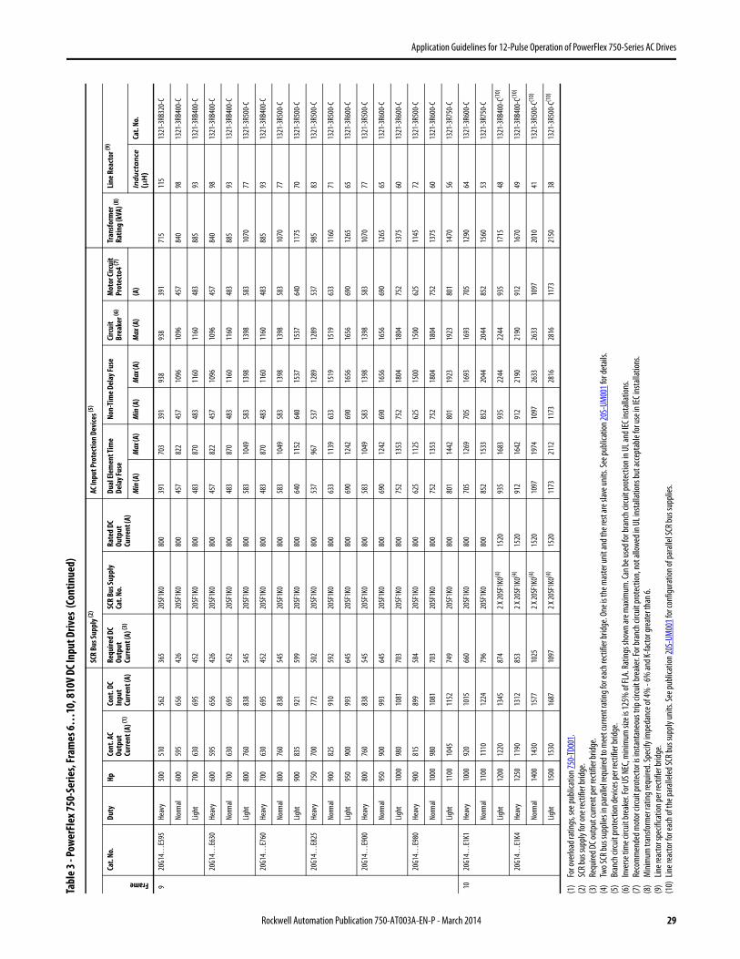
Application Guidelines for 12-Pulse Operation of PowerFlex 750-Series AC Drives
920
G14…
E595
Heav
y50
051
056
236
520
SF1K
080
039
170
339
193
893
839
171
511
513
21-3
RB32
0-C
Norm
al60
059
565
642
620
SF1K
080
045
782
245
710
9610
9645
784
098
1321
-3RB
400-
C
Light
700
630
695
452
20SF
1K0
800
483
870
483
1160
1160
483
885
9313
21-3
RB40
0-C
20G1
4…E6
30He
avy
600
595
656
426
20SF
1K0
800
457
822
457
1096
1096
457
840
9813
21-3
RB40
0-C
Norm
al70
063
069
545
220
SF1K
080
048
387
048
311
6011
6048
388
593
1321
-3RB
400-
C
Light
800
760
838
545
20SF
1K0
800
583
1049
583
1398
1398
583
1070
7713
21-3
R500
-C
20G1
4…E7
60He
avy
700
630
695
452
20SF
1K0
800
483
870
483
1160
1160
483
885
9313
21-3
RB40
0-C
Norm
al80
076
083
854
520
SF1K
080
058
310
4958
313
9813
9858
310
7077
1321
-3R5
00-C
Light
900
835
921
599
20SF
1K0
800
640
1152
640
1537
1537
640
1175
7013
21-3
R500
-C
20G1
4…E8
25He
avy
750
700
772
502
20SF
1K0
800
537
967
537
1289
1289
537
985
8313
21-3
R500
-C
Norm
al90
082
591
059
220
SF1K
080
063
311
3963
315
1915
1963
311
6071
1321
-3R5
00-C
Light
950
900
993
645
20SF
1K0
800
690
1242
690
1656
1656
690
1265
6513
21-3
R600
-C
20G1
4…E9
00He
avy
800
760
838
545
20SF
1K0
800
583
1049
583
1398
1398
583
1070
7713
21-3
R500
-C
Norm
al95
090
099
364
520
SF1K
080
069
012
4269
016
5616
5669
012
6565
1321
-3R6
00-C
Light
1000
980
1081
703
20SF
1K0
800
752
1353
752
1804
1804
752
1375
6013
21-3
R600
-C
20G1
4…E9
80He
avy
900
815
899
584
20SF
1K0
800
625
1125
625
1500
1500
625
1145
7213
21-3
R500
-C
Norm
al10
0098
010
8170
320
SF1K
080
075
213
5375
218
0418
0475
213
7560
1321
-3R6
00-C
Light
1100
1045
1152
749
20SF
1K0
800
801
1442
801
1923
1923
801
1470
5613
21-3
R750
-C
1020
G14…
E1K1
Heav
y10
0092
010
1566
020
SF1K
080
070
512
6970
516
9316
9370
512
9064
1321
-3R6
00-C
Norm
al11
0011
1012
2479
620
SF1K
080
085
215
3385
220
4420
4485
215
6053
1321
-3R7
50-C
Light
1200
1220
1345
874
2 X 20
SF1K
0(4)
1520
935
1683
935
2244
2244
935
1715
4813
21-3
RB40
0-C(1
0)
20G1
4…E1
K4He
avy
1250
1190
1312
853
2 X 20
SF1K
0(4)
1520
912
1642
912
2190
2190
912
1670
4913
21-3
RB40
0-C(1
0)
Norm
al14
0014
3015
7710
252 X
20SF
1K0(4
)15
2010
9719
7410
9726
3326
3310
9720
1041
1321
-3R5
00-C
(10)
Light
1500
1530
1687
1097
2 X 20
SF1K
0(4)
1520
1173
2112
1173
2816
2816
1173
2150
3813
21-3
R500
-C(1
0)
(1)
For o
verlo
ad ra
tings
, see
publi
catio
n 750
-TD0
01.
(2)
SCR b
us su
pply
for o
ne re
ctifie
r brid
ge.
(3)
Requ
ired D
C out
put c
urre
nt pe
r rec
tifier
bridg
e.(4
)Tw
o SCR
bus s
uppl
ies in
para
llel re
quire
d to m
eet c
urre
nt ra
ting f
or ea
ch re
ctifie
r brid
ge. O
ne is
the m
aste
r unit
and t
he re
st ar
e slav
e unit
s. Se
e pub
licat
ion 20
S-UM
001 f
or de
tails
.(5
)Br
anch
circu
it pr
otec
tion d
evice
s per
recti
fier b
ridge
.(6
)In
verse
tim
e circ
uit br
eake
r. For
US N
EC, m
inim
um si
ze is
125%
of FL
A. Ra
tings
show
n are
max
imum
. Can
be us
ed fo
r bra
nch c
ircuit
prot
ectio
n in U
L and
IEC i
nsta
llatio
ns.
(7)
Reco
mm
ende
d mot
or ci
rcuit
prot
ecto
r is in
stant
aneo
us tr
ip cir
cuit
brea
ker. F
or br
anch
circu
it pr
otec
tion,
not a
llowe
d in U
L ins
talla
tions
but a
ccep
tabl
e for
use i
n IEC
insta
llatio
ns.
(8)
Min
imum
tran
sform
er ra
ting r
equir
ed. S
pecif
y im
peda
nce o
f 4%
- 6%
and K
-facto
r gre
ater
than
6.(9
)Lin
e rea
ctor s
pecif
icatio
n per
recti
fier b
ridge
.(1
0)Lin
e rea
ctor f
or ea
ch of
the p
arall
eled S
CR bu
s sup
ply u
nits.
See p
ublic
ation
20S-
UM00
1 for
conf
igura
tion o
f par
allel
SCR b
us su
pplie
s.
Tabl
e 3 - P
ower
Flex
750-
Serie
s, Fr
ames
6…10
, 810
V DC
Inpu
t Driv
es (C
ontin
ued)
SCR
Bus S
uppl
y (2)
AC In
put P
rote
ctio
n De
vice
s (5)
Frame
Cat.
No.
Duty
HpCo
nt. A
C Ou
tput
Cu
rrent
(A) (1
)
Cont
. DC
Inpu
t Cu
rrent
(A)
Requ
ired
DC
Outp
ut
Curre
nt (A
) (3)
SCR
Bus S
uppl
yCa
t. No
.Ra
ted
DC
Outp
ut
Curre
nt (A
)
Dual
Elem
ent T
ime
Dela
y Fus
eNo
n-Ti
me D
elay
Fuse
Circ
uit
Brea
ker (6
)M
otor
Circ
uit
Prot
ecto
4 (7)
Tran
sform
er
Ratin
g (k
VA) (8
)Li
ne R
eact
or (9
)
Min
(A)
Max
(A)
Min
(A)
Max
(A)
Max
(A)
(A)
Inductance
(µ
H)
Cat.
No.
Rockwell Automation Publication 750-AT003A-EN-P - March 2014 29
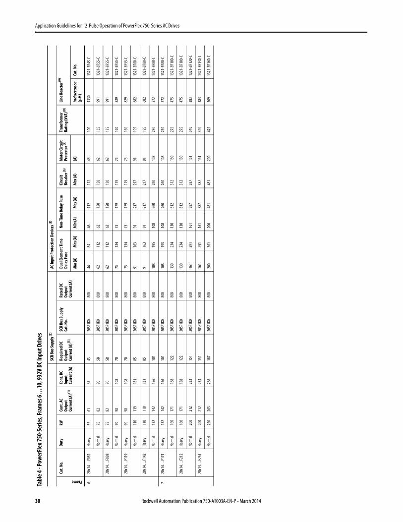
Application Guidelines for 12-Pulse Operation of PowerFlex 750-Series AC Drives
Tabl
e 4 - P
ower
Flex
750-
Serie
s, Fr
ames
6…10
, 932
V DC
Inpu
t Driv
es
SCR
Bus S
uppl
y (2)
AC In
put P
rote
ctio
n De
vice
s (5)
Frame
Cat.
No.
Duty
kWCo
nt. A
C Ou
tput
Cu
rrent
(A) (1
)
Cont
. DC
Inpu
t Cu
rrent
(A)
Requ
ired
DC
Outp
ut
Curre
nt (A
) (3)
SCR
Bus S
uppl
yCa
t. No
.Ra
ted
DC
Outp
ut
Curre
nt (A
)
Dual
Elem
ent T
ime
Dela
y Fus
eNo
n-Ti
me D
elay
Fuse
Circ
uit
Brea
ker (6
)M
otor
Circ
uit
Prot
ecto
r (7)
Tran
sform
er
Ratin
g (k
VA) (8
)Li
ne R
eact
or (9
)
Min
(A)
Max
(A)
Min
(A)
Max
(A)
Max
(A)
(A)
Inductance
(µ
H)
Cat.
No.
620
x14…
F082
Heav
y55
6167
4320
SF1K
080
046
8446
112
112
4610
013
3013
21-3
R45-
C
Norm
al75
8290
5820
SF1K
080
062
112
6215
015
062
135
991
1321
-3R5
5-C
20x1
4…F0
98He
avy
7582
9058
20SF
1K0
800
6211
262
150
150
6213
599
113
21-3
R55-
C
Norm
al90
9810
870
20SF
1K0
800
7513
475
179
179
7516
082
913
21-3
R55-
C
20x1
4…F1
19He
avy
9098
108
7020
SF1K
080
075
134
7517
917
975
160
829
1321
-3R5
5-C
Norm
al11
011
913
185
20SF
1K0
800
9116
391
217
217
9119
568
213
21-3
R80-
C
20x1
4…F1
42He
avy
110
110
131
8520
SF1K
080
091
163
9121
721
791
195
682
1321
-3R8
0-C
Norm
al13
214
215
610
120
SF1K
080
010
819
510
826
026
010
823
057
213
21-3
R80-
C
720
x14…
F171
Heav
y13
214
215
610
120
SF1K
080
010
819
510
826
026
010
823
057
213
21-3
R80-
C
Norm
al16
017
118
812
220
SF1K
080
013
023
413
031
231
213
027
547
513
21-3
R100
-C
20x1
4…F2
12He
avy
160
171
188
122
20SF
1K0
800
130
234
130
312
312
130
275
475
1321
-3R1
00-C
Norm
al20
021
223
315
120
SF1K
080
016
129
116
138
738
716
134
038
313
21-3
R130
-C
20x1
4…F2
63He
avy
200
212
233
151
20SF
1K0
800
161
291
161
387
387
161
340
383
1321
-3R1
30-C
Norm
al25
026
328
818
720
SF1K
080
020
036
120
048
148
120
042
530
913
21-3
R160
-C
30 Rockwell Automation Publication 750-AT003A-EN-P - March 2014
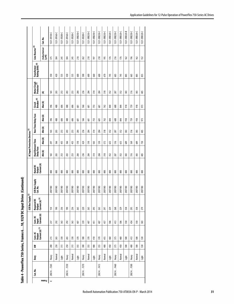
Application Guidelines for 12-Pulse Operation of PowerFlex 750-Series AC Drives
820
G14…
F265
Heav
y20
021
523
715
420
SF1K
080
016
529
716
539
639
616
535
037
513
21-3
R130
-C
Norm
al25
026
529
219
020
SF1K
080
020
336
620
348
848
820
343
030
413
21-3
R160
-C
Light
315
330
363
236
20SF
1K0
800
253
455
253
606
606
253
535
245
1321
-3R2
00-C
20G1
4…F3
30He
avy
250
265
292
190
20SF
1K0
800
203
366
203
488
488
203
430
304
1321
-3R1
60-C
Norm
al31
533
036
323
620
SF1K
080
025
345
525
360
660
625
353
524
513
21-3
R200
-C
Light
355
370
407
265
20SF
1K0
800
284
510
284
681
681
284
600
218
1321
-3RB
250-
C
20G1
4…F3
70He
avy
300
308
339
220
20SF
1K0
800
236
424
236
566
566
236
500
262
1321
-3R2
00-C
Norm
al35
537
040
726
520
SF1K
080
028
451
028
468
168
128
460
021
813
21-3
RB25
0-C
Light
400
410
451
293
20SF
1K0
800
314
565
314
753
753
314
660
197
1321
-3RB
250-
C
20G1
4…F4
15He
avy
355
370
407
265
20SF
1K0
800
284
510
284
681
681
284
600
218
1321
-3RB
250-
C
Norm
al40
041
545
729
720
SF1K
080
031
857
231
876
276
231
867
019
513
21-3
RB25
0-C
Light
450
460
506
329
20SF
1K0
800
352
633
352
844
844
352
745
176
1321
-3RB
320-
C
20G1
4…F4
60He
avy
375
375
413
268
20SF
1K0
800
287
516
287
688
688
287
605
216
1321
-3RB
250-
C
Norm
al45
046
050
632
920
SF1K
080
035
263
335
284
484
435
274
517
613
21-3
RB32
0-C
Light
500
500
550
358
20SF
1K0
800
383
689
383
918
918
383
805
162
1321
-3RB
320-
B
20G1
4…F5
00He
avy
400
413
454
295
20SF
1K0
800
316
569
316
759
759
316
665
196
1321
-3RB
250-
C
Norm
al50
050
055
035
820
SF1K
080
038
368
938
391
891
838
380
516
213
21-3
RB32
0-C
Light
530
530
583
379
20SF
1K0
800
405
730
405
973
973
405
855
152
1321
-3RB
320-
C
Tabl
e 4 - P
ower
Flex
750-
Serie
s, Fr
ames
6…10
, 932
V DC
Inpu
t Driv
es (C
ontin
ued)
SCR
Bus S
uppl
y (2)
AC In
put P
rote
ctio
n De
vice
s (5)
Frame
Cat.
No.
Duty
kWCo
nt. A
C Ou
tput
Cu
rrent
(A) (1
)
Cont
. DC
Inpu
t Cu
rrent
(A)
Requ
ired
DC
Outp
ut
Curre
nt (A
) (3)
SCR
Bus S
uppl
yCa
t. No
.Ra
ted
DC
Outp
ut
Curre
nt (A
)
Dual
Elem
ent T
ime
Dela
y Fus
eNo
n-Ti
me D
elay
Fuse
Circ
uit
Brea
ker (6
)M
otor
Circ
uit
Prot
ecto
r (7)
Tran
sform
er
Ratin
g (k
VA) (8
)Li
ne R
eact
or (9
)
Min
(A)
Max
(A)
Min
(A)
Max
(A)
Max
(A)
(A)
Inductance
(µ
H)
Cat.
No.
Rockwell Automation Publication 750-AT003A-EN-P - March 2014 31

Application Guidelines for 12-Pulse Operation of PowerFlex 750-Series AC Drives
920
G14…
F590
Heav
y45
046
050
632
920
SF1K
080
035
263
335
284
484
435
274
517
613
21-3
RB32
0-C
Norm
al56
059
064
942
220
SF1K
080
045
281
345
210
8410
8445
295
513
713
21-3
RB40
0-C
Light
630
650
715
465
20SF
1K0
800
497
895
497
1193
1193
497
1050
124
1321
-3RB
400-
C
20G1
4…F6
50He
avy
500
500
550
358
20SF
1K0
800
383
689
383
918
918
383
805
162
1321
-3RB
320-
C
Norm
al63
065
071
546
520
SF1K
080
049
789
549
711
9311
9349
710
5012
413
21-3
RB40
0-C
Light
710
710
781
508
20SF
1K0
800
544
978
544
1305
1305
544
1145
114
1321
-3R5
00-C
20G1
4…F7
10He
avy
560
590
649
422
20SF
1K0
800
452
813
452
1084
1084
452
955
137
1321
-3RB
400-
C
Norm
al71
071
078
150
820
SF1K
080
054
497
854
413
0513
0554
411
4511
413
21-3
R500
-C
Light
800
790
869
565
20SF
1K0
800
605
1088
605
1451
1451
605
1275
102
1321
-3R5
00-C
20G1
4…F7
65He
avy
630
650
715
465
20SF
1K0
800
497
895
497
1193
1193
497
1050
124
1321
-3RB
400-
C
Norm
al75
076
584
254
720
SF1K
080
058
610
5458
614
0614
0658
612
3510
613
21-3
R500
-C
Light
850
860
946
615
20SF
1K0
800
658
1185
658
1580
1580
658
1385
9413
21-3
R600
-C
20G1
4…F7
95He
avy
710
750
825
536
20SF
1K0
800
574
1033
574
1377
1377
574
1210
108
1321
-3R5
00-C
Norm
al80
079
587
556
920
SF1K
080
060
910
9560
914
6114
6160
912
8510
213
21-3
R500
-C
Light
900
960
1056
686
20SF
1K0
800
735
1322
735
1763
1763
735
1545
8413
21-3
R600
-C
20G1
4…F9
60He
avy
800
795
875
569
20SF
1K0
800
609
1095
609
1461
1461
609
1285
102
1321
-3R5
00-C
Norm
al90
096
010
5668
620
SF1K
080
073
513
2273
517
6317
6373
515
4584
1321
-3R6
00-C
Light
1000
1020
1122
729
20SF
1K0
800
781
1405
781
1874
1874
781
1645
7913
21-3
R600
-C
1020
G14…
E1K1
Heav
y90
086
595
261
920
SF1K
080
066
211
9266
215
8915
8966
213
9593
1321
-3R6
00-C
Norm
al10
0010
4011
4474
420
SF1K
080
079
614
3379
619
1119
1179
616
7578
1321
-3R6
00-C
Light
1100
1150
1265
822
2 X 20
SF1K
0(4)
1520
880
1584
880
2112
2112
880
1855
7013
21-3
RB40
0-C(1
0)
20G1
4…E1
K4He
avy
1120
1160
1276
829
2 X 20
SF1K
0(4)
1520
888
1599
888
2131
2131
888
1870
7013
21-3
RB40
0-C(1
0)
Norm
al14
0014
0015
4010
012 X
20SF
1K0(4
)15
2010
7219
2910
7225
7225
7210
7222
5558
1321
-3R5
00-C
(10)
Light
1500
1485
1634
1062
2 X 20
SF1K
0(4)
1520
1137
2046
1137
2728
2728
1137
2395
5413
21-3
R500
-C(1
0)
(1)
For o
verlo
ad ra
tings
, see
publi
catio
n 750
-TD0
01.
(2)
SCR b
us su
pply
for o
ne re
ctifie
r brid
ge.
(3)
Requ
ired D
C out
put c
urre
nt pe
r rec
tifier
bridg
e.(4
)Tw
o SCR
bus s
uppl
ies in
para
llel re
quire
d to m
eet c
urre
nt ra
ting f
or ea
ch re
ctifie
r brid
ge. O
ne is
the m
aste
r unit
and t
he re
st ar
e slav
e unit
s. Se
e pub
licat
ion 20
S-UM
001 f
or de
tails
.(5
)Br
anch
circu
it pr
otec
tion d
evice
s per
recti
fier b
ridge
.(6
)In
verse
tim
e circ
uit br
eake
r. For
US N
EC, m
inim
um si
ze is
125%
of FL
A. Ra
tings
show
n are
max
imum
. Can
be us
ed fo
r bra
nch c
ircuit
prot
ectio
n in U
L and
IEC i
nsta
llatio
ns.
(7)
Reco
mm
ende
d mot
or ci
rcuit
prot
ecto
r is in
stant
aneo
us tr
ip cir
cuit
brea
ker. F
or br
anch
circu
it pr
otec
tion,
not a
llowe
d in U
L ins
talla
tions
but a
ccep
tabl
e for
use i
n IEC
insta
llatio
ns.
(8)
Min
imum
tran
sform
er ra
ting r
equir
ed. S
pecif
y im
peda
nce o
f 4%
- 6%
and K
-facto
r gre
ater
than
6.(9
)Lin
e rea
ctor s
pecif
icatio
n per
recti
fier b
ridge
.(1
0)Lin
e rea
ctor f
or ea
ch of
the p
arall
eled S
CR bu
s sup
ply u
nits.
See p
ublic
ation
20S-
UM00
1 for
conf
igura
tion o
f par
allel
SCR b
us su
pplie
s.
Tabl
e 4 - P
ower
Flex
750-
Serie
s, Fr
ames
6…10
, 932
V DC
Inpu
t Driv
es (C
ontin
ued)
SCR
Bus S
uppl
y (2)
AC In
put P
rote
ctio
n De
vice
s (5)
Frame
Cat.
No.
Duty
kWCo
nt. A
C Ou
tput
Cu
rrent
(A) (1
)
Cont
. DC
Inpu
t Cu
rrent
(A)
Requ
ired
DC
Outp
ut
Curre
nt (A
) (3)
SCR
Bus S
uppl
yCa
t. No
.Ra
ted
DC
Outp
ut
Curre
nt (A
)
Dual
Elem
ent T
ime
Dela
y Fus
eNo
n-Ti
me D
elay
Fuse
Circ
uit
Brea
ker (6
)M
otor
Circ
uit
Prot
ecto
r (7)
Tran
sform
er
Ratin
g (k
VA) (8
)Li
ne R
eact
or (9
)
Min
(A)
Max
(A)
Min
(A)
Max
(A)
Max
(A)
(A)
Inductance
(µ
H)
Cat.
No.
32 Rockwell Automation Publication 750-AT003A-EN-P - March 2014

Application Guidelines for 12-Pulse Operation of PowerFlex 750-Series AC Drives
Notes:
Rockwell Automation Publication 750-AT003A-EN-P - March 2014 33

Publication 750-AT003A-EN-P - March 2014 Copyright © 2014 Rockwell Automation, Inc. All rights reserved. Printed in the U.S.A.
Rockwell Automation SupportRockwell Automation provides technical information on the Web to assist you in using its products.At http://www.rockwellautomation.com/support you can find technical and application notes, sample code, and links to software service packs. You can also visit our Support Center at https://rockwellautomation.custhelp.com/ for software updates, support chats and forums, technical information, FAQs, and to sign up for product notification updates.
In addition, we offer multiple support programs for installation, configuration, and troubleshooting. For more information, contact your local distributor or Rockwell Automation representative, or visithttp://www.rockwellautomation.com/services/online-phone.
Installation Assistance
If you experience a problem within the first 24 hours of installation, review the information that is contained in this manual. You can contact Customer Support for initial help in getting your product up and running.
New Product Satisfaction Return
Rockwell Automation tests all of its products to help ensure that they are fully operational when shipped from the manufacturing facility. However, if your product is not functioning and needs to be returned, follow these procedures.
Documentation Feedback Your comments will help us serve your documentation needs better. If you have any suggestions on how to improve this document, complete this form, publication RA-DU002, available at http://www.rockwellautomation.com/literature/.
United States or Canada 1.440.646.3434
Outside United States or Canada Use the Worldwide Locator at http://www.rockwellautomation.com/rockwellautomation/support/overview.page, or contact your local Rockwell Automation representative.
United States Contact your distributor. You must provide a Customer Support case number (call the phone number above to obtain one) to your distributor to complete the return process.
Outside United States Please contact your local Rockwell Automation representative for the return procedure.
U.S. Allen-Bradley Drives Technical Support - Tel: (1) 262.512.8176, Fax: (1) 262.512.2222, E-mail: [email protected]: www.ab.com/support/abdrives