application manual - wolseley.co.uk · pipe fittings ... measure the pipe circumference (2) with a...
TRANSCRIPT

C F C / H C F C F R E ES I N C F C / H C F CC F C / H C F C F R E E
Application Manual


3
Page
Introduction ..................................................................................4Basic rules and useful tips for the application of nmc insulation products .......................................................... 5List of tools ................................................................................. 6nmc ancillary products ................................................................7New installation pipework ........................................................... 8Insulating existing pipework installations .................................. 10Pipe fittings ................................................................................ 11Ninety degree bends .................................................................12Segmented bends (lobster back) ...............................................14Pipe elbow ................................................................................ 16T. piece method 1 ......................................................................20T. piece method 2 ..................................................................... 22Screwed T. piece fitting ............................................................ 23Small valves ............................................................................. 24Gate valves ............................................................................... 25Strainer valves .......................................................................... 32Flanges ......................................................................................39Mitre & sharp bends ................................................................. 42Double layering of pipework ..................................................... 46Sheet insulation to flat or curved surfaces ................................47Removable caps ....................................................................... 48Insulation Tape ......................................................................... 50The use of trace heating ........................................................... 51Application and storage temperatures ...................................... 52Technical information on Austenitic Stainless Steel ................. 53Insulating pipes installed underground ..................................... 54

4
This nmc insulation application manual is a basic guide to assistthe installer to use the recommended techniques for the correctapplication of Insul Tube®, Insul Sheet®, k-flex Eco, Climaflex,Mondoflex and k-flex Solar HT.
It is intended as a reminder of the basic rules and procedures forthe experienced installer, also as a step by step guide for begin-ners.
Please contact nmc UK ltd. for any additional information.
nmc (uk) ltd.Tafarnaubach Industrial Estate • Tredegar • South Wales NP22 3AA
Customer Services Department direct lines – Tel: 01495 713266 • Fax: 01495 713277
Website: www.nmc-uk.com • E-mail: [email protected]
Introduction
5
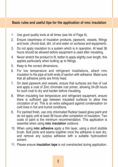
1. Use good quality tools at all times (see list of Page 6).2. Ensure cleanliness of insulation products, pipework, vessels, fittings
and tools. (Avoid dust, dirt, oil and water on surfaces and equipment).3. Do not apply insulation to a system which is in operation. At least 36
hours should be allowed before equipment is used after insulating.4. Never stretch the product to fit, better to apply slightly over length, this
applies particularly when butting up to fittings.5. Keep to the correct dimensions.6. For low temperature and refrigerant installations, attach nmc
insulation to the pipe at both ends of section with adhesive. Make surethat all adhesive joints are firmly fixed.
7. On steel pipework and vessels, ensure that surfaces are free of rustand apply a coat of Zinc chromate rust primer, allowing 24-28 hoursfor such coat to dry and harden before insulating.
8. When insulating low temperature and refrigerant equipment, ensurethere is sufficient gap between insulated surfaces to allow freecirculation of air. This is an extra safeguard against condensation oncold lines in hot and humid conditions.
9. For painted finish, use only chlorinated Rubber based gloss paint anddo not apply until at least 36 hours after completion of insulation. Twocoats of paint is the minimum recommendation. This application isessential when using nmc insulation outdoors.
10. When using nmc adhesive apply a thin layer, using a short stubblebrush. Butt joints and seams together once the adhesive is tack dry,and remove any surplus adhesive with a suitable hydrocarbonsolvent.
11. Please ensure insulation tape is not overstrected during application.
Basic rules and useful tips for the application of nmc insulation

6
• Carpenter’s expanding metal rule.• Tape measure.• Blackboard chalk/marker.• 1 long blade knife not stainless steel.• 1 short blade knife keep sharp at all times.• Metal straight edge.• Tee square.• Scissors.• Dividers.• Calipers.• Mitre box.• Whetstone/File.• Brush (short firm bristles).• Slitting knife and spare blades.• Templates.• Clamps.• Punches.
List of tools
}

7
Non flammable adhesive available in 1/4, 1/2
and 1 litre tins.
Insulation Tape3mm thick x 50mm wide.
Ancillary products

8
Sleeve pipe insulation along the pipework for straight runs.
Also around drawn bends.
NOTE : Pipe insulation must be eased along the pipework bypushing, NEVER PULL.
New installation pipework

9
When brazing pipe joints or fittings, ease the insulation back alongthe pipe by 8” (20 cm) on each side of joint and retain with clamps.
When the brazed joint has fully cooled, apply a brush coat ofadhesive to each butt joint, when set, press joints together.
New installation pipework
10
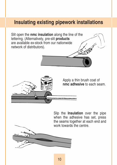
Slit open the nmc insulation along the line of the lettering. (Alternatively, pre-slit productsare available ex-stock from our nationwidenetwork of distributors).
Apply a thin brush coat ofnmc adhesive to each seam.
Slip the Insulation over the pipewhen the adhesive has set, pressthe seams together at each end andwork towards the centre.
Insulating existing pipework installations

11
Unions (heavy bronzeand screwed fittings).
Butt nmc insulation toeach side of the fittingand apply insulationtape on the fitting tomatch the wall thicknessof the insulation used.
Please ensure insulation tape isnot overstretched duringapplication.
Use oversize pipe or sheetinsulation of correctdimensions to cover thefitting, overlap the pipeinsulation by 1" (25 mm) onboth sides of fitting.
Slip the oversize section intoposition and apply adhesive to the seams, when set press firmlytogether.
Pipe fittings
12
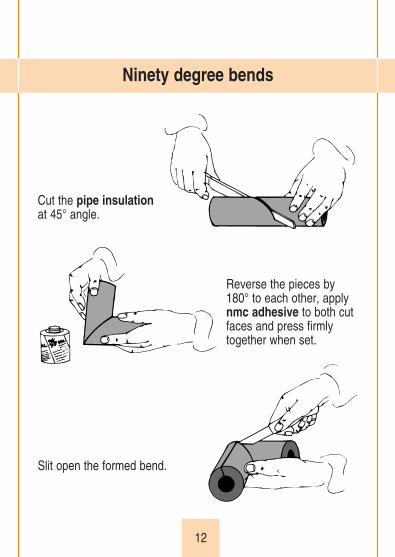
Cut the pipe insulationat 45° angle.
Reverse the pieces by180° to each other, applynmc adhesive to both cutfaces and press firmlytogether when set.
Slit open the formed bend.
Ninety degree bends
13
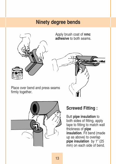
Apply brush coat of nmcadhesive to both seams.
Place over bend and press seams firmly together.
Screwed Fitting :
Butt pipe insulation toboth sides of fitting, applytape to fitting to match wallthickness of pipeinsulation. Fit bend (madeup as above) to overlappipe insulation by 1" (25mm) on each side of bend.
Ninety degree bends
14
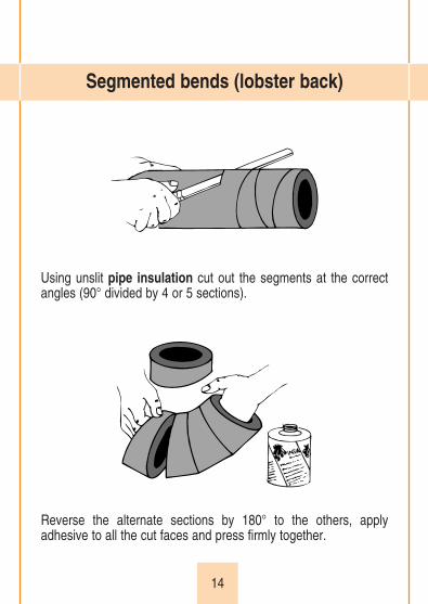
Using unslit pipe insulation cut out the segments at the correctangles (90° divided by 4 or 5 sections).
Reverse the alternate sections by 180° to the others, applyadhesive to all the cut faces and press firmly together.
Segmented bends (lobster back)
15
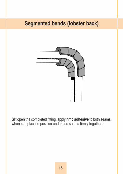
Slit open the completed fitting, apply nmc adhesive to both seams,when set, place in position and press seams firmly together.
Segmented bends (lobster back)

16
Measure the inner radius (1).
Measure the pipe circumference (2) with a strip of sheet insulation.(DO NOT STRETCH IT).
Pipe elbow
2
1

17
Transfer dimensions toinsulation sheet:- small arc = (1), - large arc = (1) + 1/2 (2).
Mark out fully with dividers, the two half sections.
Pipe elbow
21

18
Cut out the sections and applynmc adhesive to the longseams.
Join the two sections at one end.
Press the opposite ends toge-ther and working to the centrecomplete the seam. TURN THE ELBOW OVER,PRESS THE SEAM FIRMLYTOGETHER ON THE INSIDE.
Pipe elbow
19
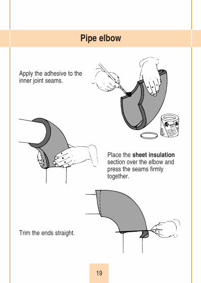
Apply the adhesive to the inner joint seams.
Place the sheet insulationsection over the elbow andpress the seams firmlytogether.
Trim the ends straight.
Pipe elbow
20
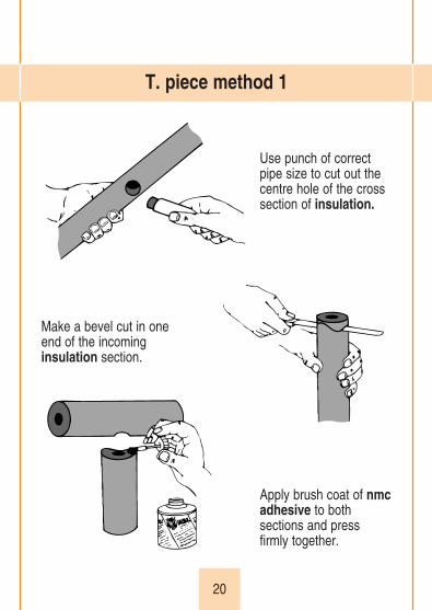
Use punch of correctpipe size to cut out thecentre hole of the crosssection of insulation.
Make a bevel cut in one end of the incoming insulation section.
Apply brush coat of nmcadhesive to bothsections and pressfirmly together.
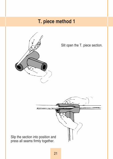
T. piece method 1
21
Slit open the T. piece section.
Slip the section into position and press all seams firmly together.
T. piece method 1
22
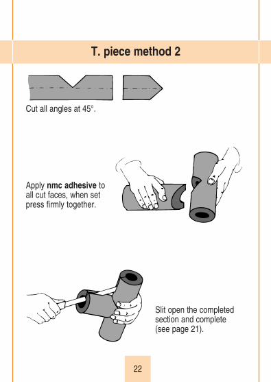
Cut all angles at 45°.
Apply nmc adhesive to all cut faces, when set press firmly together.
Slit open the completedsection and complete (see page 21).
T. piece method 2

23
Butt insulation to either side of fitting, apply insulation tape tomatch the wall thickness of the insulation.Make up and apply an oversize section as shown above. Overlap the insulation by 1" (25 mm) on each side of fitting.
Screwed T. piece fitting

24
Butt insulation up toeach side of the valve,apply tape to the valveto match the wall thick-ness of the insulation.
Make up an oversize section and apply as shown overpage. Overlap the insulation by 1" (25 mm) on each side of the valve.
Small valves

25
Measure, mark out on sheet insulation and cut out a pair of flange rings. Place in position.
Gate valves

26
Measure the circumference of the flanges (I).(DO NOT STRETCHTHE sheet insulationSTRIP)
Measure the distance between the outer facesof the flange rings (II) and the O/D of the valve neck (III).
Gate valves
I
III II

27
Transfer these dimensions to the sheet insulation and cut outthe valve body cover.
Apply adhesive to flange rings, inside strip andseam of valve cover, place into position andpress all joints firmlytogether
Gate valves
III II
I

28
Measure the flange length (A)and width (B) if oval (O/D if circular) and transfer tosheet insulation.
Cut out the flange disc, usingpunch cut hole for valve spindle,slit at one side, apply adhesive toseam and place into position.
Gate valves
AB

29
Measure the flange ring circumference, the short (I) and long (II) heights of valve neck.
Transfer the measurements to the sheet insulation marking the width out in four equal divisions.
Gate valves
I
II
III
IIII
30
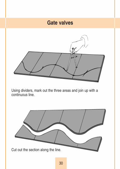
Using dividers, mark out the three areas and join up with a continuous line.
Cut out the section along the line.
Gate valves

31
Chamfer the inside edge at the highest areas.
Apply adhesive to theedge of flange disc, toinside and seam ofcover, place in positionand press all jointsfirmly together. Finally,apply adhesivebetween valve neckand valve body cover.
Gate valves
32
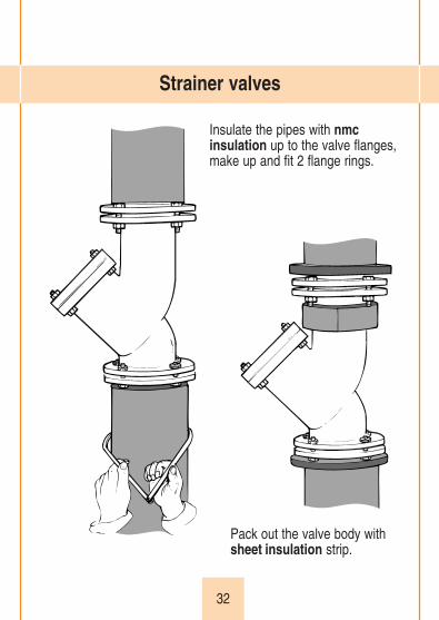
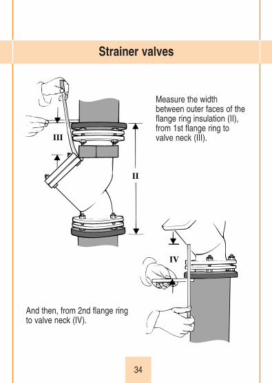
Insulate the pipes with nmcinsulation up to the valve flanges,make up and fit 2 flange rings.
Pack out the valve body withsheet insulation strip.
Strainer valves

33
Measure the flange circumference(I).(DO NOT STRETCH THEsheet insulation STRIP).
Mark this dimension, onto thesheet insulation.
Strainer valves
I
34
Measure the widthbetween outer faces of theflange ring insulation (II),from 1st flange ring tovalve neck (III).
And then, from 2nd flange ring to valve neck (IV).
Strainer valves
III
II
IV

35
Transfer all dimensions to the sheet insulation,mark up and cut out the valve body cover.
Apply adhesive to the seams, when set place over valve and press firmly together.
Strainer valves
IV
III
I
II

36
Using a strip of sheetinsulation, measure the lengthof the three available sides ofthe cover (A). (DO NOT STRETCH STRIP).Tranfer this dimension to yoursheet insulation.
Measure distance fromtop of valve toinsulated valve body athighest point (B).
Strainer valves
A
B

37
Using dividers, mark out two arcs of radius (B) and join the top ofthe arcs with a continuous line.
Cut out the completed sections.
Strainer valves
A
B

38
Cut a chamfer edge on thelower inside of the cover.
Apply a brush coat of adhesive to bothseams, place into position and press seams firmly together.Finally apply adhesivebetween the two insulatedsections of the body andthe cover and then sealthe insulation section tothe cover rim.
Strainer valves

39
Using calipers, measure the O/Ds of theinsulated pipe and the flange.
Mark out the flange rings with dividers andcut out with a sharp knife.
Flanges
40
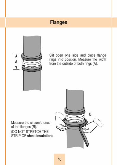
Slit open one side and place flangerings into position. Measure the widthfrom the outside of both rings (A).
B
Measure the circumference of the flanges (B).(DO NOT STRETCH THE STRIP OF sheet insulation)
Flanges
A

41
Mark out the width (A) and circumference dimensions (B)onto the sheet insulation, then cut out the cover.
Apply adhesive to the flangerings, on the inside and theseam of the cover strip, placeover flange and press alljoints firmly together.Finally, apply adhesive bet-ween the pipe insulation andthe flange rings.
Flanges
A
A
B

42
Measure circumference of bend (I).(DO NOT STRETCH sheetinsulation STRIP)
Measure the outer height of bend (II).
Measure the inner height ofbend (III).
Mitre & sharp bends
I
II
III
43
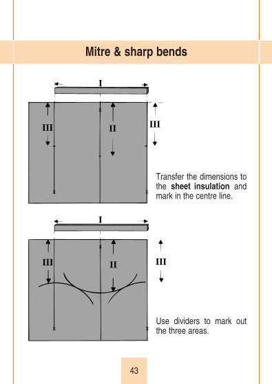
Transfer the dimensions tothe sheet insulation andmark in the centre line.
Use dividers to mark outthe three areas.
Mitre & sharp bends
III II III
I
III II III
I

44
Join up the three areas and cut along it to form the two sections of the bend.
Apply adhesive to the butt joints,when set press together to form thebend.
Mitre & sharp bends
45
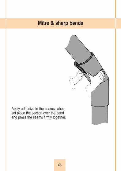
Apply adhesive to the seams, when set place the section over the bend and press the seams firmly together.
Mitre & sharp bends
46
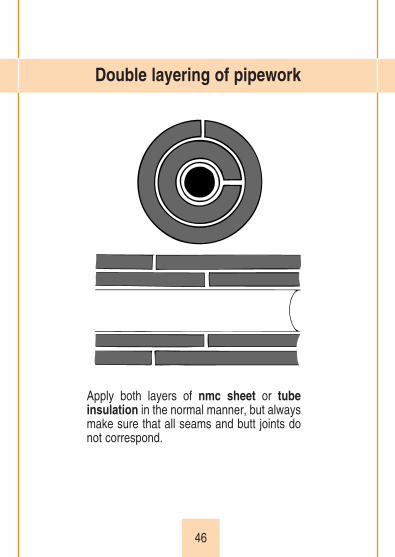
Apply both layers of nmc sheet or tubeinsulation in the normal manner, but alwaysmake sure that all seams and butt joints donot correspond.
Double layering of pipework

47
nmc sheet insulation is suitable for use on all ducts, vessels andtanks.
Draw up a work schedule of the sizes needed to complete the jobin hand and calculate the most efficient combinations availablefrom the standard sheets or rolls of nmc sheet insulation. In thisway unnecessary waste is avoided. Always cut oversize, allow 6mm (1/4") to both length and width. Apply adhesive to the inner sur-face of the sheet as well as to the metal surfaces. Because of itsflexibility, nmc sheet insulation is ideal for insulating awkwardirregular shapes. Chalk lines applied directly onto the metal surfacecan be transferred to nmc sheet insulation. Press it firmly againstthe marked surface for an accurate image of the required outline.For repetition work, make up templates from sheet metal or othersuitable material that is available. Use them only to mark out, ascutting the nmc sheet insulation directly against templates willreduce their effective life.
Sheet insulation to flat or curved surfaces

48
For hot lines a band is often used to secure the cap in position. Inthe case of cold, chilled and refrigerant systems, the cap should besufficiently well fitted to prevent condensation problems.
Removable caps

49
The removable cover is built up insections to form a tight fitting cap.
For ease of application, letter theindividual components with chalk as they are made.
Allow sufficient time for the adhesiveto be fully set, then test all joints forfirmness by fixing and removing the cap2 - 3 times.
Removable caps

50
nmc tape used to complement nmc insulation products to fillgaps in fittings, to achieve neat, tight joints at brackets and flangeson ductwork and vessels. It is useful to effect quick efficient repairsto damage on existing insulated systems.
nmc tape is the modern solution to insulating short lengths of pipe-work and fittings in cramped spaces and hard-to-reach locations.We recommend a double spiral wrap of tape with a 50% overlapusing as many layers as necessary to meet the specified wallthickness.To insulate valves, fittings and irregular shapes, cut tape to therequired length and mould to suit the particular shape. Ensure that all surface areas are fully insulated by the tape andapply further layers as necessary.Please ensure nmc tape is not overstretched during application.
Insulation Tape

51
Care should be taken when specifying trace heating tapes for usewith insulation and must not exceed the upper temperature of anynmc insulation products.
We recommend a maximum tape temperature of 80°C on line, thisshould cover surge temperatures and not reach the upper limit ofnmc insulation products.
The line temperatures show on the technical data of the tapeliterature piece and in some cases on the tape itself, this relates tothe temperature limitations of the pipe to which the tape is beingapplied not the temperature the tape can achieve.
Trace heating tapes normally used on domestic cold water pipesshould fit the criteria but still check to make sure the upper servicelimit will not be breached.
The use of trace heating tapes with nmc insulation products

52
It is recommended that nmc synthetic foam rubber andthermoplastic products are stored between 5°C and 25°C. Theideal application temperature is between 20°C and 25°C althoughthe material can be fitted at temperatures between 5°C and 25°C.
AdhesivesStorage Temperature +10°C to +25°C Application Temperature +5°C to +25°C
PaintsStorage Temperature +10°C to +25°CApplication Temperature +5°C to +25°C in dry conditions
System 2000 PrimerStorage Temperature +5°C to +35°C Application Temperature +5°C to +30°CUsable life at 5°C 4 days, at 30°C 24 hours
System 2000 CoatingsStorage Temperature +5°C to +40°CApplication Temperature +5°C to +30°C in dry conditionsThe recommended maximum application temperature with paintsis to stop premature drying and allow proper bonding to the surfaceto which it is being applied.
Application and Storage Temperatures of all nmc UK products

53
Please use Fosters Heat Resistant Coating 57-73 with theexception of K Flex Eco which does not contain any chloride ionsand may therefore be used on stainless steel without anyprotective measures.
Coverage Rates of nmc Accessories
Technical Information Bulletin on the use of nmc (uk) ltdInsulation Materials on Austenitic Stainless Steel
nmc Accessories Coverage
Insul & Climaflex Adhesives Sheets – 2.2 sq metres per litre
Tubes – 60 Linear metres per litre, butt ends and seams
Insul & Climaflex Paints 4 sq metres per litre
System 2000 Coating 1st Coat 1.5 sq. metre per kilo2nd Coat 2.5 sq. metre per kilo
54
1. Use tubular nmc (uk) Ltd products in preference to slit materialwherever practical to reduce the number of seams in thesystem.
Maintain the design thickness of insulation at all valves,strainers, flanges or other fitments and ensure that the systemis properly vapour sealed at these points.
2. Once the system is fully insulated and all adhesive joints arefully cured (allow a minimum of 24 hours), wrap the nmcinsulation products with a suitable hydrophobic, waterproofingtape, e.g. Denso tape or equivalent installed in accordance withthe manufacturers' recommendations.
3. Enclose the insulated and wrapped system within a rigid PVCsoil pipe to provide protection for the nmc insulation productsagainst compression and soil movement.
a) For applications above the water table, put 10mm drain holes at intervals of approximately 600mm along the bottom centre of the PVC soil pipe (prior to installation over insulation).
b) For applications where the system is or may on occasion be below the water table, do not put in any drain holes but seal the push fit joints of the soilpipe with a suitable waterproof mastic or use a continuously welded PVC pipe system.
Insulating pipes installed underground


NMC (uk) Ltd reserves the right to change or modify any of the technical data orsize range of its products without prior notice. The data contained in this manual arefor informative purposes only. The correct application of our products is theresponsibility of the user.This manual or part of it can only be reproduced after prior written authorization.