application note 1035 - rs online · line carrying data, ... turbine, to medium/high voltage for...
TRANSCRIPT

IntroductionOptical fiber technology has changed data communication transfer especially in the industrial environment, where data must be transferred between machines rapidly while still ensuring high reliability. Optical fiber is typically fabricated from either transparent plastic (POF = plastic optical fiber) or glass. Optical fibers provides many advantages:
• The dielectric material eliminates ground loop and common mode noise problems. It also isolates large common mode voltage since there is no direct electrical contact between transmitter and receiver.
• It is immune to electromagnetic interference (EMI). This prevent signal interference as well as coupled noise between neighboring cables.
• It can protect equipment from excessive voltage, and ensure data integrity by eliminating the hazard of generating sparks.
Avago Technologies can provide a complete, higly reliable, and low cost optical link solution using our versatile link (VL) family of components consisting of Transmitter, Receiver, plastic optical fiber (POF) cable, and connectors for different applications. Maximum optical link distances are guaranteed at Industrial temperature range (-40°C to +85°C).
Avago’s Optical link using Versatile link (VL) components
Versatile Link Family
Application Note 1035
ContentsThis application note introduces Avago Technologies versatile link family (VLF) and includes the following topics:
• Application Examples• Versatile link family (VLF) description • Part number selection guide • Available options• Summary of Data rate and Link distances• Evaluation kits• Application note literature
• VLF Mechanical dimension and foot prints• Interlocked assembly• Plastic optical fiber (POF)• Plastic fiber connectors (PFC) styles• Step-by-Step instruction of connectorizing POF cable• Connector alignment principle

2
Figure 1c. Point of Sales Terminals
Figure 1d. GPIB (IEEE-488) Bus Extender
Figure 1b. Robot Controller
Figure 1a. Programmble Logic Controller
Application ExamplesDifferent application have different requirements and therefore, different reasons for using fiber optics. The following paragraphs discusses a few examples of common fiber optic application and why fiber optics are used in those applications.
The first type of application utilizes the EMI immunity of fiber-optics for data transmission in electrically noisy envi-ronments. A good example is data transmission between a programmable logic controller (PLC) and the computer that is directing it, illustrated in Figure 1a. The two computers might be in a factory containing machinery that generates large amounts of electrical noise. Data transmission lines commonly run along-side lines that supply power to the machinery. There may be large amounts of electrical noise present on the power lines caused by the machinery. This noise can couple electromagnetically into any adjacent lines. If one of those adjacent lines is twisted-pair or coax line carrying data, the coupled electrical noise may signifi-cantly interfere with the data transmission. The noise may cause only periodic errors, or it might completely corrupt
all of the data being sent. Because optical fiber is not sus-ceptible to EMI, it can eliminate the undesirable coupling of noise from the power lines on to the data lines and ensure error-free data transmission.
Figures 1b, 1c, and 1d illustrate other applications which utilize the EMI immunity of fiber optics. Figure 1b shows how bending properties of POF can connect a robot con-troller with the cell controller and the robot. The fiber eliminates the large amounts of noise generated by the motors, solenoids, etc. that are part of the robot. Figure 1c illustrates how fiber is used to network point-of-sales terminals (cash registers) in a retail store. Fiber optics ensures that sales information is not corrupted or lost due to noise generated inside the building. Figure 1d shows fiber optics connecting two GPIB (IEEE-488) data buses. The GPIB data bus is commonly used to connect test in-struments in manufacturing automated test systems. Again, fiber optics eliminates the noise that is commonly present in a factory and ensures that correct test data is transferred to the test system controller.

3
Figure 2a. Industrial Data Acquisition System
Figure 2b. X-Ray Machine
Figure 2c. Lightning Protection
Figures 2a, 2b, and 2c also illustrate the use of fiber in voltage-isolation applications. Figure 2a is a simple block diagram of an industrial data acquisition system. The fiber protects the system from the high voltage sensed by the sensor. This system can be used to monitor patient behavior. Figure 2b shows the use of fiber in a clinical
X-ray machine. The fiber isolates the high voltages used to power the X-ray tube and provides EMI immunity from the noise generated by switching high voltages and currents. Figure 2c illustrates how fiber can protect electronic equipment from the high voltages generated by nearby lightning strikes.

4
Figure 3. Block diagram of Wind Turbine Power Generation
Global warming and climate change has created huge market for alternative power generation. Wind turbine energy has become a popular alternative to meet the fast growing energy demand. Wind turbine power is used to convert kinetic energy into electrical energy. A rectifier, inverter, transformer and filter are needed within the wind turbine for utility-grade AC power to be transmitted over long distance (Figure 3) A transform-er is usually installed at the tower bottom to provide voltage conversion from low voltage generated by wind turbine, to medium/high voltage for transmission. Fiber optic components offer protection by providing insula-tion from high-voltage glitches and unwanted signals in power electronics devices. These products can be installed to operate in close proximity to power-carrying conduits which emit disruptive electrical interference since fiber optic provides high immunity to EMI.
Figure 4. Block diagram of Solar Power Generation
The key application for industrial fiber optic components in wind turbine system includes:
• Power electronics gate driver for rectifiers and inverters
• Control and communication boards
• Turbine control units
• Condition monitoring systems
• Wind farm networking
Solar energy has also become popular alternative energy source to meet demands of human being. Figure 4 shows the block diagram of solar power generation system. The key application for the industrial fiber optic com-ponents in solar energy systems include:
• Power electronic gate drivers for inverters
• Control and communication boards
• Substation automation and protection relays

5
Another application example for versatile link family is in static VAR compensator (SVC). It provides very fast system response caused by reactive power fluctuations in high voltage electricity systems. In modern high voltage power networks SVC devices secure power stability and power quality. SVC utilizes Thyristor-Switched Capacitors (TSCs) and Thyristor-Controlled Reactor (TCR) to compensate the unbalanced load (Figure 5). TSC and TCR operate and switch on/off at high voltage and current. This creates very high electromagnetic fields that will induce electrical noise into nearby copper lines. Fiber optic cables are the best medium for sending control signals to the devices in SVC systems because they are immune to electromagnet-ic fields, no capacitive coupling and it provides galvanic isolation.
Figure 5. Block diagram of SVC system
Another example is an optoelectronic arc flash detection system (Figure 6) in a protective relay, it is possible to minimize the time needed to trigger the circuit breaker when a system fault occurs. The light intensity during an arc-flash event is significantly higher than the normal light background. The light surge is created from the initiation of the flash and is easily detected using proven technology. Lens-point sensors and bare fiber-optic sensors are most commonly implemented for optical detection. This system can be used remotely. Fiber optic cable properties of isolation, EMI insensitive and no crosstalk is utilized.
Figure 6. Arc flash detection system

6
Another application of VLF is in Power inverters. A power inverter is a device that converts direct current (DC) to alternating current (AC). An inverter is necessary if the electrical source provides direct current (such as batteries, solar panels, or fuel cells), but the device to be powered needs alternating current to work. Large power inverters normally use IGBTs (Insulated Gate Bipolar Transistor) for switching (Figure 7). To control these IGBTs fiber optic cable are ideal because they provide galvanic isolation and the EMI immunity.
Figure 7. IGBT’s Gate Driver Block Diagram
Figure 8. Gaming machine
Gaming machines (Figure 8) offer three different possible applications for the use fiber optic components. The first is within the machine itself, for the connection between the control unit and user interface. The second ap-plication provides a secure and hack-free connection between the single gaming machine and the central computer monitoring the single machines. The last one is a player tracking system. For this the communication is between the single gaming machines connected to support networked gaming

7
Figure 9. Versatile link family (VLF) components
Versatile Link Family (VLF) Description The versatile link series is a complete fiber optic link component family for application requiring a low cost solution. The HFBR-0500Z and HFBR-0500ETZ series includes transmitters, receivers, connectors and connector cables. This provides system designer an easy way to build an optical system in industrial , medical or other enviro-ments. The optical system link design is simplified by the logic compatible receivers and complete specification for each component.
VLF products are available at commercial temperature range (0°C to 70°C) as well as for industrial temperature range (-40°C to 85°C). This ensures reliable circuit operation and guarantees maximum link distances. Table 1 and Table 2 summarizes the data rate and distance capabilities of versatile link family for commerical and industrial tem-perature range respectively. Typical distances at room temperature are also shown. The maximum data rates for versatile link components ranges from 40 kBd to 155 MBd.
The VLF, shown in Figure 9, is intended for use with 1 mm plastic optical flber (POF) and hard clad silica (HCS) fiber. No optical design is required because the speci-fications include any connector losses at the transmit-ter and at the receiver. The transmitter module contains 650 nm large area LED's that can be easily interfaced to all standard logic familes. The receiver module contains optics detector with TTL/CMOS compatible output except HFBR-2526Z. The compact, low-profile package is color
coded to distinguish transmitters from receivers; transmit-ter module is in gray color and receiver module is in blue color except 2528Z. Both horizontal and vertical package styles are available with standard 8-pin DIP pinouts. The packages can also be interlocked or stacked (“n-plexed”) to decrease the required amount of PC-board space.
The data sheet for the versatile link family contains complete guaranteed specification for entire links and in-dividual components, electrical pin outs, interface circuits, connectoring information, mechanical dimensions, part number and ordering information.
Reliability data sheets are available which provide complete reliability information for all versatile compo-nents.

8
– x x x x ET ZHFBRHFBR x x x x ET Z
1 = Transmitter (TX)1 = Transmitter (TX)
2 = Receiver (RX)2 = Receiver (RX)
Z = RoHS CompliantZ = RoHS Compliant
ET = Extended Temperature RangeET = Extended Temperature Range
AFBRAFBR
5 = 650nm TX and RX products5 = 650nm TX and RX products
6 = 650nm Tx (IC +LED) and Rx (Integrated PD) products6 = 650nm Tx (IC +LED) and Rx (Integrated PD) products
ET = Extended Temperature RangeET = Extended Temperature Range
1 = 5 MBd High Performance Link1 = 5 MBd High Performance Link(Integrated PD) products(Integrated PD) products
2 = Horizontal Package2 = Horizontal Package
3 = Vertical Package3 = Vertical Package
2 = 1 MBd High Performance Link2 = 1 MBd High Performance Link
3 = 40 KBd Low Current/Extended distance Link3 = 40 KBd Low Current/Extended distance Link
4 = 1 MBd Standard Link / 50 MBd Non‐Inverted 4 = 1 MBd Standard Link / 50 MBd Non‐Inverted
4 = Tilted (30°) Package4 = Tilted (30°) Package 5 = 12 MBd Receiver5 = 12 MBd Receiver
7 = 155 MBd Transmitter7 = 155 MBd Transmitter
6 = 155 MBd Receiver6 = 155 MBd Receiver
7 = 155 MBd Transmitter7 = 155 MBd Transmitter
8 = 10 MBd High Performance Link8 = 10 MBd High Performance Link
9 = 10/50 MBd Transmitter and Receiver9 = 10/50 MBd Transmitter and Receiver
Figure 10. Part number selection guide of VLF components
Part Number Selection GuideThe figure below shows the part number selection guide for VLF components.
Available options
Vertical Packages
HFBR-x531Z HFBR-x532Z HFBR-x533Z
HFBR-x531ETZ HFBR-x532ETZ
Tilted (30°) Packages
AFBR-x644Z HFBR-x541ETZ HFBR-x542ETZ
Horizontal Packages
HFBR-x521Z HFBR-x522Z HFBR-x523Z HFBR-x524Z
AFBR-x624Z AFBR-x629Z HFBR-x521ETZ HFBR-x522ETZ
HFBR-x525EZ HFBR-1527Z HFBR-2526Z HFBR-1527ETZ
HFBR-2526ETZ AFBR-x529Z

9
Summary of Data rate and Link distance
Table 1. Summary of Data rate and Link distance for xxxxZ
Versatile Link Family
Guaranteed Minimum Link Length (m) Typical Link Length (m)
0° C to +70° C 25° C 25° C
Standard Cable
Improved Cable
Standard Cable
Improved Cable
Standard Cable
Improved Cable
Extended Link distance 40 KBd 94 111 138 154 110 125
Standard Performance 1 MBd 8 10 17 19 43 48
High Performance 1 MBd 39 45 47 56 70 78
High Performance 5 MBd 19 22 27 27 48 53
Table 2. Summary of Data rate and Link distance for xxxxETZ
Versatile Link Family
Guaranteed Minimum Link Length (m) Typical Link Length (m)
-40° C to +85° C 25° C 25° C
Standard Cable
Improved Cable
Standard Cable
Improved Cable
Standard Cable
Improved Cable
High Performance 1 MBd 37 43 58 67 78 87
High Performance 5 MBd 17 20 33 38 53 58
DC-50 MBd 45 50 45 50 45 50
Application Note (AN) Literature
AN Description1080 DC to 10 MBd Versatile link with plastic optical
fiber or Hard clad slica for factor automation and industrial control application (AV02-0784EN)
1109 LED Safety
1137 Generic printed circuit layout rules for low cost fiber optics components (AV02-0879EN)
5341 Electronic circuits for Avago POF components (AV02-3323EN)
5374 74AC08, Alternative LED transmitter driver chip for DC-10 MBd (AV02-1027EN)
Evaluation Kits
Evaluation Kit DescriptionModule Part No.
HFBR-0501Z DC to 5 MBd, 650 nm POF HFBR-x521Z
HFBR-0502Z DC to 1 MBd, 650 nm POF HFBR-x522Z
HFBR-0503Z DC to 40 KBd, 650 nm POF HFBR-x523Z
AFBR-0546Z DC to 50 MBd, 650 nm POF AFBR-x624Z
AFBR-0547Z DC to 50 MBd, 650 nm POF AFBR-x529Z
AFBR-0548Z DC to 50MBd, 650 nm POF AFBR-x624Z
Example: HFBR-0502Z, 1MBd Versatile linkThis kit contains: HFBR-1522 Tx, HFBR-2522 Rx, polishing kit, 3 styles of plastic connectors, Bulk head feed through, 5 m of 1 mm POF cable, lapping film, grit paper and HFBR-0500Z data sheet.

10
Mechanical Dimensions
Tilted (30°) Package
Dimensions in Millimeters (Inches)
2.03(0.080)
10.16(0.400)
5.08(0.200)
6.86(0.27)
18.80(0.740)
18.29(0.720)
6.86(0.270)
10.16(0.400)
4.19(0.165)
1.27(0.050)2.54
(0.100)
0.51(0.020)
18.8(0.74)
2.03(0.080)
7.62(0.30)
0.64(0.025)
7.62(0.300)
2.77(0.109)
1.85(0.073)
0.64 (0.025) DIA.
5.08(0.200)
3.81 (0.150) MAX.3.56 (0.140) MIN.
7.62(0.300)
2.54(0.100)
0.4(0.02)
5.2
(0.2
1)
10.2
(0.4
0)
B
18.7
(0.74)
30°
2(0
.08)
∅0.7(0.03)
0.5(0.02)
6.6
(0.2
6)
2.8
(0.1
1)15
.2(0
.60)
4.6
(0.1
8)0.
6(0
.03)
A
1.1(0.05)
2.2(0.09)
19.3(0.76)
1.3(0.05)
8.7(0.34)
10.1(0.40)
Dimensions in Millimeters (Inches)
Dimensions in Millimeters (Inches)
Horizontal Package Vertical Package
11
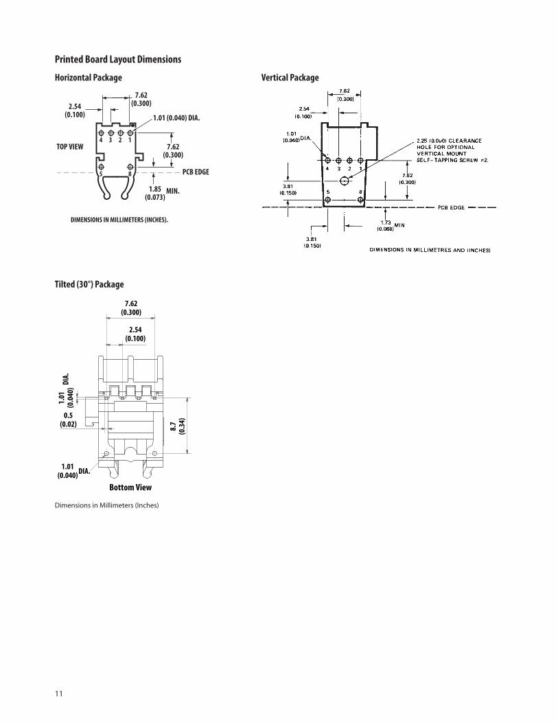
Printed Board Layout Dimensions
Tilted (30°) Package
Dimensions in Millimeters (Inches)
4 13 2
5 8
7.62(0.300)
1.01 (0.040) DIA.
1.85(0.073)
MIN.
PCB EDGE
TOP VIEW
2.54(0.100)
7.62(0.300)
DIMENSIONS IN MILLIMETERS (INCHES).
Horizontal Package Vertical Package
7.62(0.300)
2.54(0.100)
0.5(0.02) 8.
7(0
.34)
1.01
(0.0
40)
Bottom View
1.01(0.040) DIA.
DIA.

12
Interlocked (Stacked) AssembliesHorizontal packages may be stacked by placing units with pins facing upward. Initially engage the interlocking mechanism by sliding the L bracket body from above into the L slot body of the lower package. Use a straight edge, such as a ruler, to bring all stacked units into uniform alignment. This technique prevents potential harm that could occur to fingers and hands of assemblers from the package pins. Stacked horizontal package can be disen-gaged if necessary. Repeated stacking and un stacking causes no damage to individual units.
To stack vertical packages, hold one unit in each hand, with the pin facing away and the optical ports on the bottom. Slide the L bracket unit into the L slot unit. The straight edge used for horizontal package alignment is not needed. (Figure 11)
Stacking - Horizontal Package Stacking - Vertical Package
Stacking - Tilted (30°) Package
Figure11. Interlocked (stacked) horizontal, vertical and tilted (30°) packages

13
Plastic Optical Fiber (POF) CableThe HFBR-C/R/EXXYYYZ series of plastic optical fiber (POF) cables are constructed of a single step-index fiber sheathed in a black polyethylene jacket. The duplex fiber consists of two simplex fibers joined with a zipcord web
Standard (Type = ”R”) and Extra Low Loss (Type = ”E”) cables comply with UL VW-1 flame retardant specification (UL file #E89328) except for Ordinary (Type = ”C”)
Features• Compatible with Avago Versatile Link Family of
connectors and fiber optic components
• 1 mm diameter POF in 3 grades
– Ordinary POF with 0.22 dB/m typical attenuation (0° C to 70° C)
– Standard POF with 0.22 dB/m typical attenuation (-40° C to 85° C)
– High performance extra low loss POF with 0.19 dB/m typical attenuation (-40° C to 85° C)
Cables are available in unconnectored or connectored options. Refer to the ordering guide of POF cable or contact your Avago representative or official distributors.
Odering guide of POF cable
Cable CodeR = Standard Attenuation POF E = Extra Low Loss POF C = Ordinary POF
HFBR – Z
Connector CodeU = Unconnectored N = Standard Simplex Connectors L = Latching Simplex ConnectorsM = Standard Duplex ConnectorsT = Latching Duplex Connectors
RoHS Compliant
Length Code(measured from connector tip to tip of connector)Maximum 500 meters (not 1 meter increments)e.g. 010 = 10 meters
Channel CodeS = Simplex Connector D = Duplex Zipcord Cable
For Example:HFBR-RUD500Z is a Standard attenuation, Unconnec-tored, Duplex, 500 meter cable.
HFBR-RLS001Z is a Standard attenuation, Latching Simplex Connectored, Simplex, 1 meter cable.
HFBR-RMD010Z is a Standard attenuation, Standard Duplex Connectored, Duplex, 10 meter cable.
HFBR-RMD100Z is a Standard attenuation, Standard Duplex Connectored, Duplex, 100 meter cable.
Cable Length Tolerances: The plastic cable length tolerances are: Max. +10% and Min. 0%

14
Plastic Fiber Connector (PFC) StylesThere are two types of connectors available for versatile link family:
1. Crimp Ring Connectors
2. Crimpless Connectors
Crimp Ring Connectors DescriptionThere are four connector styles are available for termina-tion of plastic optical fiber (POF): simplex non-latching, simplex latching, duplex non-latching and duplex latching. All connectors provide a snap-in action when mated to versatile link components.
Simplex connectors are color coded to facilitate identifi-cation of transmitter and receiver connections. Duplex connectors are keyed so that proper orientation is ensured during insertion. If the POF cable/connector will be used at extreme operating temperatures or experience frequent and wide temperature cycling effects, the cable/connector attachment can be strengthened with an RTV adhesive (see Plastic connectoring Instructions for more detail). The connectors are made of a flame retardant VALOX UL94 V-0 material (UL file # E121562)
SIMPLEX CONNECTOR STYLES
HFBR- 4501Z/4511Z – Simplex, Non-LatchingThe simplex connector provides a quick and stable con-nection for applications that require a component-to-connector retention force of 8N (1.8lb).
These connectors are available in gray (HFBR-4501Z) or blue (HFBR-4511Z).
HFBR-4503Z/4513Z – Simplex, LatchingThe simplex latching connector is designed for rugged applications requiring a greater retention force 80N (18lb) – than provided by a simplex non-latching connector. When inserting the simplex latching connector into a module, the connector latch mechanism should be aligned with the top surface of the horizontal modules, or with the tall vertical side of the vertical modules. Misalignment of an inserted latching connector into either module will not result in a positive latch. The connector is released by depressing the rear section of the connector lever, and then pulling the connector assembly away from the module housing.
The simplex latching connector is available in gray (HFBR-4503Z) or blue (HFBR-4513Z).
Figure12. Simplex Crimp Ring - HFBR-4525Z Figure13. Simplex Crimp Ring - HFBR-4513Z

15
DUPLEX CONNECTOR STYLES
HFBR- 4516Z – Duplex, LatchingThe duplex latching connector is designed for rugged applications requiring greater retention force than the non latching duplex connector. When inserting the duplex latching connector into a module, the connector latch mechanism should be aligned with the top surface of the dual combination of horizontal or vertical versatile link components.
The duplex latching connector is available in gray (HFBR-4516Z).
Mechanical characteristics of Crimp ring Connectors
Parameter Part Number Symbol Min Typ Units Temp °C NoteRetension force toHFBR-0500Z series
Simplex, Non-LachingHFBR-4501Z/4511Z
FR-C 7 8 N 25 1
3 N -40 to +85
Simplex, LatchingHFBR-4503Z/4513Z
FR-C 47 80 N 25 1
11 N -40 to +85
Duplex, Non-LatchingHFBR-4506Z
FR-C 7 12 N 25 1
4 N -40 to +85
Duplex, LatchingHFBR-4516Z
FR-C 50 80 N 25 1
15 N -40 to +85
Note:1. Retention force of non-latching connectors is lower at elevated temperatures. Latching connectors are recommended for applications where a
high retention force at higher temperature is desired
HFBR- 4506Z – Duplex, Non-LatchingDuplex connectors provide convenient duplex cable ter-mination and are keyed to prevent incorrect insertion into duplex configured modules. The duplex connector is compatible with dual combinations of horizontal or vertical versatile link components (e.g., two horizontal transmitters, two vertical receivers, a horizontal transmit-ter with a horizontal receiver, etc.).
The duplex non-latching connector is available in parchment, off-white (HFBR-4506Z).
Figure14. Duplex Crimp Ring - HFBR-4506Z Figure15. Duplex Crimp Ring - HFBR-4516Z

16
Crimpless ConnectorsThe HFBR-453xZ series are an enhanced version of HFBR-450xZ series low cost connectors for POF, which are compatible with versatile link series transmitters and receivers. The innovative design uses a simple, snap- together concept which eliminates the need for crimping. This connector not only saves the user labor and tool cost, but reduces the yield loss due to installation error. The HFBR-453xZ connectors are available in two types: Non-Latching and Latching. The connectors are made of a rugged, flame retardant plastic which is good for industrial and other harsh environments. The HFBR-453xZ connector series are available in three colors: Black, Blue and Grey. The color code help to match transmitter and receiver and make it easier for the user to differentiate between fiber connections especially when there are a large number.
Duplex ConnectorsDuplex connector is prepared from two simplex connec-tors. Place one connector on top of the other, so that the top half of each connector is over the ferrule half of the opposite connector. Manually press connectors together in the center of the arrangement. Then latch by pressing on the sides of each connector.
Figure16. Crimpless Non-Latching and Latching connectors Figure17. Crimpless Duplex Connector
Mechanical characteristics of Crimpless Connectors
Parameter Part Number Symbol Min Typ Units Temp °C NoteRetension force toHFBR-0500Z series
Simplex, Non-LachingHFBR-453xZ
FR-C 8 12 N 25 1
2.5 N -40 to +85
Duplex Configuration, Non-LatchingHFBR-453xZ
FR-C 14 24 N 25 1
4 N -40 to +85
Tensile Force, Connector to Cable
HFBR-4531Z FT 40 50 N -40 to +85
HFBR-4532Z
Note:1. Retention force of non-latching connectors is lower at elevated temperature.
Figure 17a shows the average retention force for simplex and duplex non-latching connectors over temperature range. The average retention force decreases from – 40°C to +85°C for both connectors. As a thumb rule for versatile connectors the average retention force for duplex con-nectors is approximately 1.7 times the average retention force of simplex connectors.
0
5
10
15
20
25
30
‐40° ° +85°C
Aver
age R
eten
tion
force
(N)
Temperature (°C)
Simplex - Nonlatching - HFBR-453xZDuplex - Nonlatching - HFBR-453xZ
+25°C
Figure 17a. Average Retention force of simplex and duplex connectors over industrial temperature range

17
Step-by-Step Plastic Cable Connectorizing InstructionsThe following step-by-step guide describes how to terminate POF cable. It is ideal for both field and factory installation. Connectors can be easily installed on cable ends with wire strippers, cutters and with/without crimping tool.
Finishing the cable is accomplished with the Avago HFBR-4593Z polishing kit, consisting of a polishing fixture, 600 grit abrasive paper and 3 μm pink lapping film. The connector can be used immediately after polishing.
Figure18. AFBR-4593Z Polishing kit
Materials needed for POF cable termination are:
1. Avago Plastic Optical Fiber Cable (Example: HFBR- EUD500Z).
2. Fiber cutter (e.g Fiberfin / Scissor).
3. 16 Gauge Latching Wire Strippers (Example: Ideal Strip-master TM type 45-092).
4. HFBR-4597Z Crimping Tool.
5. HFBR-4593Z Polishing Kit.
6. Crimp Ring Connectors or Crimpless Connectors.
Step 1: Cutting the POF CableInsert the POF cable into the POF cutter. Press downward the cutter handle to cut the POF cable. You can use these cutter to cut cable of required length.
Figure19. Inserting POF cable into POF cutter
With using the duplex connector arrangement, the separated duplex cable should be stripped to roughly equal lengths on each cable end. The zip cord structure of the duplex cable permits easy separation of the channels. The channels should be separated a minimum of 100 mm (4 in) to a maximum of 150 mm (6 in) back from the ends to permit connectorizing and polishing.
Step 2: Stripping of POF CableAfter cutting the cable to the desired length, strip off approximately 7 mm (0.3 in) of the outer jacket with the 16 gauge wire strippers.
Figure 20. POF cable stripping using Ideal strip-master
Step 3: Inserting POF cable into Connectors
Crimp Ring ConnectorsPlace the crimp ring and connector over the end of the cable; the fiber should protrude about 3 mm (0.12 in.) through the end of the connector. Carefully position the crimp ring so that it is entirely on the connector with the rim of the crimp ring flush with the connector, leaving a small space between the crimp ring and the flange. Then crimp the ring in place with the crimping tool.
Figure 21. Inserting POF cable into crimp ring simplex and duplex connectors

18
When using the duplex connector and duplex cable, the separated duplex cable must be stripped to equal lengths on each cable. This allows easy and proper seating of the cable into the duplex connector.
Figure 22. Crimp the ring using crimping tool
Note: By convention, place the gray connector on the transmitter cable end and the blue connector on the receiver cable end to maintain color coding (different color connectors are mechanically identical).Simplex connector crimp rings cannot be used with duplex connectors and duplex connector crimp rings cannot be used with simplex connectors because of size different. The simplex crimp has a dull luster appearance; the duplex ring is glossy and has a thinner wall.
For applications with extreme temperature operation or frequent temperature cycling, improved connector to cable attachment can be achieved with the use of an RTV (GE Company, RTV-128 or Dow Corning 3145-RTV) adhesive. The RTV is placed into the connector prior to insertion of the fiber and the fiber is crimped normally. The connector can be polished after the RTV has cured and is then ready for use.
Crimpless ConnectorPlace the connector on each end of the fiber, and slide the connector down until the fiber jacket stops it. The fiber should protrude no less than 1.5 mm (0.06 in) from the end of the connector.
To install simplex connectors flip the top half of the connector over and snap it into the ferrule half (with your fingers). When the top half latches inside the body of the ferrule half, proper connector-to-cable attachment is achieved.
Figure 23. POF cable termination using simplex crimpless connector
For duplex connector installation place one connector on top of the other, so that the top half of each connector is over the ferrule half of the opposite connector. Manually press connectors together in the center of the ar-rangement. Then latch by pressing on the sides of each connector. As with the simplex version, connectors are secured when top halves latch into the ferrule halves.
Figure 24. Preparing crimpless duplex connectors
Figure 25. POF cable terminated with duplex crimpless connector

19
Note: The four dots on the bottom of the polishing fixture are wear indicator. Replace the polishing fixture when any dot is no longer visible. Typically, the polishing fixture can be used 10 times; 10 duplex con-nectors or 20 simplex connectors; two at a time.
Step 4: Trimming and PolishingAny excess fiber protruding from the connector end may be cut off with the scissor; however, the trimmed fiber should extend at least 1.5 mm (0.06 in) from the connector end. Insert the connector fully into the polishing fixture with the trimmed fiber protruding from the bottom of the fixture. This plastic polishing fixture can be used to polish two simplex connectors or simplex latching connectors simultaneously, or one duplex connector.
Figure 26. Polishing fixture for polishing process
Press the polishing tool down on the 600 grit abrasive paper. Polish the fiber using a figure eight pattern until the connector is flush with the bottom of the polishing fixture. Wipe the connector and fixture with a clean cloth or tissue.
Note: The pink polishing film provides improvement of approximately 2 dB in coupling performance of either a transmitter receiver link or a bulk-head/splice over a 600 grit polish alone. This fine polishing is com-parable to the Avago factory polish. The fine polishing step may be omitted where an extra 2 dB of optical power Is not essential; as with short link lengths. Proper polishing of the fiber/connector face results in a tip diameter between 2.5 mm (0.098 inch) minimum and 3.2 mm (0.126 inch) maximum
Figure 27. Polishing by drawing pattern 8 on abrasive paper
Step 5: FinishingPlace the flush connector and polishing fixture on the dull side of the 3 μm pink lapping film and continue to polish the fiber in the same figure eight pattern for approximate-ly 25 strokes. The fiber end should be flat, smooth and clean. This fine polish is comparable to the Avago Tech-nologies factor polish.
Figure 28. Simplex and duplex POF cable with crimp ring and crimpless solutions

For product information and a complete list of distributors, please go to our web site: www.avagotech.com
Avago, Avago Technologies, and the A logo are trademarks of Avago Technologies in the United States and other countries.Data subject to change. Copyright © 2005-2012 Avago Technologies. All rights reserved. Obsoletes 5964-40027EAV02-0730EN - August 2, 2012
Figure 29. Principle of Connector Alignment
Connector Alignment PrincipleThe Versatile Link package uses an active optical alignment system to ensure proper coupling between the connector and the package (Figure 29). The precision-molded lens on the insert is located at the bottom of a depression in the shape of a truncated cone. When the connector is inserted into the package, the jaws of the housing force the beveled end of the connector into the cone-shaped depression. This accurately centers the fiber directly above the molded lens on the insert and ensures reliable and repeatable connections.
CONNECTOR
FIBER
INSERT
LEAD FRAME
LENS
IC DIE