application note - instrumentsystems.com · conditions and advanced light measurement devices...
TRANSCRIPT
Reflective Illumination for DMS 803 / 505 DHS, SDR, VADIS, PID & PLS
The instruments of the DMS 803 / 505 series are precision goniometers for directional scanning of viewing directions with photometric and spectroradiometric light measurement devices (LMDs).
The open structure of these instruments allows for integration of a range of illumination devices, especially for reflective displays under test (DUT) and for transmissive and emissive displays under ambient illumination. The illumination devices of the DMS are designed to deliver light from a range of sources (incandescent, discharge, luminescent, etc.) under well-defined geometric conditions. The directional illumination devices can be provided with additional adjustable polarizers (linear and circular, absorptive film and birefringent crystal types). With the combination of well-controlled illumination conditions and advanced light measurement devices (spectroradiometers), the instruments DMS 505 and DMS 803 are the best choice for systematic optimization of (1) anti-glare treatments (e.g. scattering AG-layers) and for (2) non-scattering anti-reflection measures based on dielectric interference coatings and on circular polarizers.
APPLICATION NOTE // Dr. Michael E. Becker
APPLICATIONNOTE

2 APPLICATION NOTE // Reflective Illumination for DMS 803 / 505
// 1. INTRODUCTION
For the DMS 803 / DMS 505 Instrument Systems offers a range of devices for controlled illumination of the DUT with white light. The subtended angles range from 180° (2π Ω0) to less than 1°.
// 2. THE ILLUMINATION DEVICES AND THEIR APPLICATIONS
2.1 Overview
Illumination Device Feature Application
DHS - Diffusing hemisphere for extended conical illumination of reflective DUTs (e.g. LCDs) during measurement of contrast.
Measurement of contrast in reflective mode of operation.
SDR - Integrating sphere for diffuse reflectance for uniform, full hemispherical diffuse illumination with gloss trap.
Measurement of spectral reflectance and for evaluation of display performance under ambient illumination.
VADIS - Variable aperture diffuse source for conical illumination (1° – 15° subtended angle).
Measurement of surface scattering and for evaluation of display performance under ambient illumination.
PID - Parallel illumination device for directed collimated beam illumination with adjustable beam diameter.
Measurement of BRDF, etc.
PLS - Point light-source, high-luminance LED light-source for illumination during in-plane BRDF measurement.
Measurement of BRDF, specular reflectance (factor), luminance factor, etc.

2.2 DHS - Diffusing hemisphere (Illumination device with external light source)
The diffusing hemisphere DHS is designed for extended conical illumination of reflective DUTs (Fig. 1). The first devices for illumination of reflective LCDs during the measurement of contrast versus viewing direction have been designed and built at Texas Instruments (G. G. Barna, Rev. Scientific Instruments 47, 10 (1976), 1250-1260) and at the University of Karlsruhe (R. Cremers et al., Displays, 1 (1979), 12-16). The basic idea since then has been to provide illumination over a sufficiently extended solid angle to assure a constant level of incident elementary illuminance, ∆E(θ), for the sample during scanning of the viewing cone.
2.2.1 DHS - Feature
An important feature of the DHS is the slit through the north pole of the hemisphere, which is provided for two purposes:
The first half (from north pole to the equatorial plane) provides a path for the light from the display under test (DUT) to the measurement microscope;
The second half acts as a gloss trap for all angles of microscope inclination, excluding specular reflections from the front surface of the DUT.
Depending on whether specular surface reflections are
to be included or excluded during the measurement, the gloss-trap slit can be covered with a special inset (SCI/SPINC: specular components included) or left open (SCI/SPEX: specular components excluded). Fig. 2 shows an approximate hemispheric illumination of the DUT by the DHS up to an angle of light incidence (inclination) of 70° and Fig. 3 shows the DHS in two different configurations.
Depending on the constructive details of different variants of the DHS (standard DHS, DHS for temperature control chamber, etc.), the variation of differential illuminance with angle of inclination, ∆E(θ), may be different from the one shown in Fig. 4.
~Figure 2: DHS cross-section parallel to the north-polar gloss-trap slit (left). DHS cross-section perpendicular to the gloss-trap slit. The LMD (measurement microscope) does not “see” the illumination when the DUT is a mirror, specular surface reflections are thus excluded. The angle subtended by the gloss-trap slit is 10° (right).
3 APPLICATION NOTE // Reflective Illumination for DMS 803 / 505
~Figure 1: DHS with measurement microscope.
~ Figure 3: Gloss-trap slit partially closed (SCI/SPINC for microscope inclinations ≥ 10°; left); gloss-trap slit closed (microscope inclination restricted to 0°; right).

The range of illuminance levels that can be obtained with the combination of DHS and HEL-4 is between 45 000 and 65 000 lux. Fig. 5 shows the typical spectrum of irradiance provided by the DHS with the HEL-4 and a xenon discharge lamp. Depending on the light source the illuminance of the sample can be 100 000 lux and above.
2.2.2 DHS - Measurement of reflectance factor
The reflectance factor is defined as (CIE 17.4: 845-04-64) “the ratio of the reflected flux from the material within a specified detection cone to the flux that would be reflected from a perfect (reflecting) diffuser (perfectly white Lambertian surface) under the same specified illumination.”
When trying to measure the reflectance factor of a display with the DHS, the following will happen:
The DUT reflects some of the incident light back into the DHS thus affecting the net illuminance of the sample and the spectral distribution of irradiance.
When the DUT is a display comprised of several layers (e.g. LCD with touch-screen), the different optical interfaces in that stack are illuminated with different intensities due to the variation of illuminance with distance to the bottom plate of the DHS as sketched in Fig. 6.
When the reference measurement is made with the diffuse white reflectance standard, the reflected luminance is depending on the distance between the surface of the reflection standard and the bottom plate of the DHS.
As a consequence, reflectance factors should not be measured with the DHS.
The SDR has been realized to perform such measurements under well controlled and reproducible conditions.
Fig. 6 shows a variation of DUT illuminance with distance between DUT surface and DHS bottom plate.
4 APPLICATION NOTE // Reflective Illumination for DMS 803 / 505
~ Figure 4: Relative elementary illuminance, ∆E(θ), of the DHS as a function of the angle of microscope inclination. At an inclination of the measurement microscope of 8° the illuminance is maximum, and it is reduced to about 86% at an inclination of 70°.
~ Figure 5: Typical spectrum of irradiance provided by the DHS with the HEL-4 (incandescent tungsten halogen lamp, red curve) and a xenon discharge lamp (blue curve).
~Figure 6: Illuminance of DUT in close proximity to the bottom plane of the DHS (left). Illuminance of DUT removed from the bottom plane of the DHS (right).

2.3 SDR - Integrating sphere for measurement of diffuse reflectance (Illumination device with external light source) The integrating sphere based SDR is designed for measurement of the spectral reflectance, ρ(λ), under hemispherical diffuse illumination, with specular components included (SCI/SPINC) or excluded (SCE/SPEX) at an inclination angle of the light measuring device (LMD) of 8°. The SDR is an optional accessory for the DMS 803/505 (Fig. 7 and 8).
From the spectral diffuse reflectance, ρ(λ), evaluated with the SDR the chromaticity of the DUT can be evaluated with a variety of illuminants (e.g. CIE A, D65, etc.) and arbitrary illumination spectra by calculation at different illuminance levels. This procedure is described in e.g.: IEC 62341-6-2, Ed. 1: Organic light emitting diode (OLED) displays - Part 6-2: Measuring methods of visual quality and ambient performance.
In addition, the measured spectral diffuse reflectance of the DUT can be used for evaluation of the contrast of display devices (transmissive LCD+backlight, emissive OLED, etc.) under various ambient illumination conditions (i.e. intensity of illuminance and spectral distribution of illumination).
While the DHS provides multidirectional illumination for measurement of contrast of reflective displays, the SDR has been designed for measurement of chromaticity under uniform hemispherical illumination.
Fig. 9 shows a schematic representation of the SDR with two inclinations of the measurement microscope (LMD) for measuring the DUT reflectance (blue beam) and for the white reference (black beam).
5 APPLICATION NOTE // Reflective Illumination for DMS 803 / 505
~ Figure 7: SDR with measurement microscope and additional optics for modification of the focusing distance.
~Figure 8: Standard CIE geometry for hemispherical diffuse illumination and measurement of reflected radiance at an angle of inclination of 8°.

2.3.1 SDR - Geometry and operation
The initial DMS microscope aperture of 4.6° is reduced to an aperture of 1°(full subtended angle) by a supplementary optical system which also modifies the imaging properties of the microscope, so that the focus is now in the plane of the light trap port.
The axis of inclination theta intersects the center of the
viewport at the inner surface of the sphere as shown in Fig. 9. Thus the measurement beam stays centered in the viewport of the sphere when the inclination of the microscope changes. At an inclination of typically 15° the reference measurement of the luminance of the inner wall of the sphere or illuminance easily can be performed to obtain reference values for the irradiance provided by the SDR.
~Figure 9: Schematic representation of the SDR.
6 APPLICATION NOTE // Reflective Illumination for DMS 803 / 505
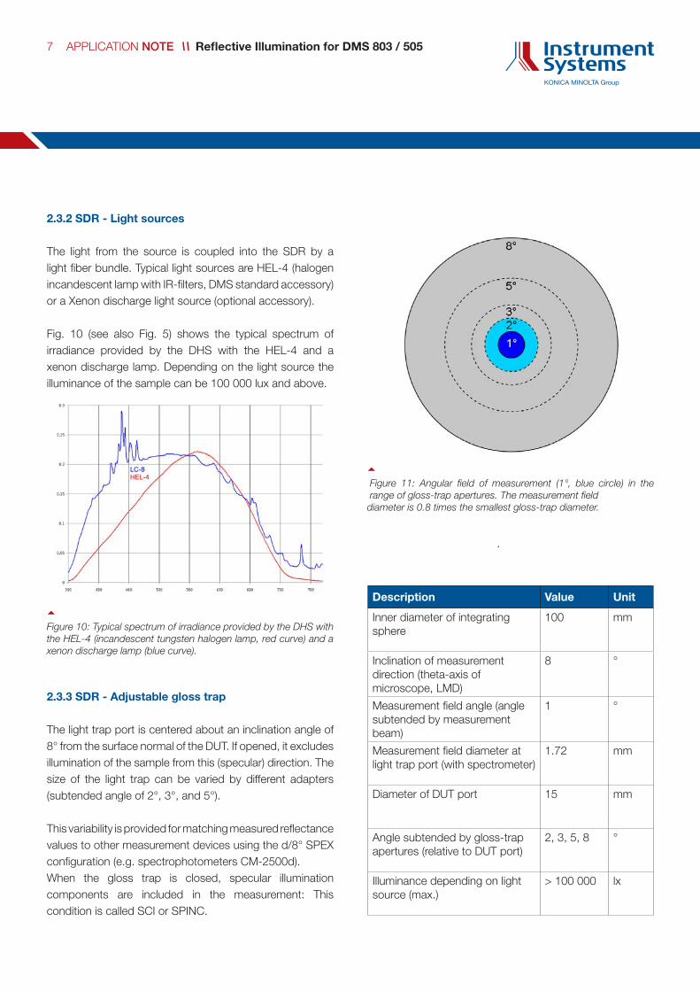
2.3.2 SDR - Light sources
The light from the source is coupled into the SDR by a light fiber bundle. Typical light sources are HEL-4 (halogen incandescent lamp with IR-filters, DMS standard accessory) or a Xenon discharge light source (optional accessory).
Fig. 10 (see also Fig. 5) shows the typical spectrum of irradiance provided by the DHS with the HEL-4 and a xenon discharge lamp. Depending on the light source the illuminance of the sample can be 100 000 lux and above.
2.3.3 SDR - Adjustable gloss trap
The light trap port is centered about an inclination angle of 8° from the surface normal of the DUT. If opened, it excludes illumination of the sample from this (specular) direction. The size of the light trap can be varied by different adapters (subtended angle of 2°, 3°, and 5°).
This variability is provided for matching measured reflectance values to other measurement devices using the d/8° SPEX configuration (e.g. spectrophotometers CM-2500d).When the gloss trap is closed, specular illumination components are included in the measurement: This condition is called SCI or SPINC.
7 APPLICATION NOTE // Reflective Illumination for DMS 803 / 505
~Figure 10: Typical spectrum of irradiance provided by the DHS with the HEL-4 (incandescent tungsten halogen lamp, red curve) and a xenon discharge lamp (blue curve).
Description Value Unit
Inner diameter of integrating sphere
100 mm
Inclination of measurement direction (theta-axis of microscope, LMD)
8 °
Measurement field angle (angle subtended by measurement beam)
1 °
Measurement field diameter at light trap port (with spectrometer)
1.72 mm
Diameter of DUT port 15 mm
Angle subtended by gloss-trap apertures (relative to DUT port)
2, 3, 5, 8 °
Illuminance depending on light source (max.)
> 100 000 lx
~ Figure 11: Angular field of measurement (1°, blue circle) in the range of gloss-trap apertures. The measurement field
diameter is 0.8 times the smallest gloss-trap diameter.

2.4 VADIS – Variable Aperture Diffuse Source (Illumination device with integrated light source)
The VADIS (Variable Aperture Diffuse Source) is an optional illumination device for the DMS series in order to perform the following measurements:
Display performance under ambient illuminance with the VADIS as illumination device for reflective displays or as a source of additional ambient illumination for transmissive and/or emissive displays with different sizes of the exit aperture (conical illumination) and at different angles of inclination or
Scattering evaluations via measurement of the luminance reflected by the sample in the specular direction as a function of the exit aperture of the VADIS, or
In-plane BRDF (Bidirectional Reflectance Distribution Function) measurements, with the exit aperture of the VADIS preferably set to the smallest size (i.e. 1°). These measurements may suffer from low reflected intensity and thus high noise level. It is recommended to use the PLS point light-source illumination with very high luminance for such measurements.
As shown in Fig. 12, the VADIS provides illumination for the complete DUT with the illuminance at a certain location being inversely proportional to the square of the distance to the VADIS exit aperture. Thus the variation of illuminance across the field of measurement (blue ellipse) is low. The measurement field on the DUT is illuminated from within the solid angle Ωa given by the exit aperture of the VADIS.
2.4.1 VADIS – Components
VADIS head with fixture arm Aperture stops (stainless steel, 1°, 2°, 3°, 5°and 10°) 15° aperture without additional stop Stabilized power supply Lens adapter for microscope (additional optics)
The luminance of the exit port of the VADIS is in the range of 12 000 to 14 000 cd/m2 depending on the aperture stop used. With decreasing aperture the amount of light reflected into the VADIS increases and thus also the luminance.
8 APPLICATION NOTE // Reflective Illumination for DMS 803 / 505
~Figure 13: VADIS mounted at the reflective illumination arm of a DMS 803.
~Figure12: The geometries of the VADIS.
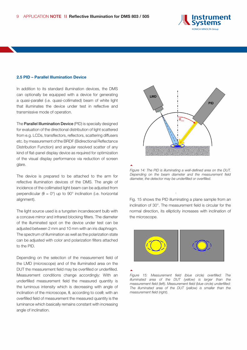
2.5 PID – Parallel Illumination Device
In addition to its standard illumination devices, the DMS can optionally be equipped with a device for generating a quasi-parallel (i.e. quasi-collimated) beam of white light that illuminates the device under test in reflective and transmissive mode of operation.
The Parallel Illumination Device (PID) is specially designed for evaluation of the directional distribution of light scattered from e.g. LCDs, transflectors, reflectors, scattering diffusers etc. by measurement of the BRDF (Bidirectional Reflectance Distribution Function) and angular resolved scatter of any kind of flat-panel display device as required for optimization of the visual display performance via reduction of screen glare.
The device is prepared to be attached to the arm for reflective illumination devices of the DMS. The angle of incidence of the collimated light beam can be adjusted from perpendicular (θ = 0°) up to 90° inclination (i.e. horizontal alignment).
The light source used is a tungsten incandescent bulb with a concave mirror and infrared blocking filters. The diameter of the illuminated spot on the device under test can be adjusted between 2 mm and 10 mm with an iris diaphragm. The spectrum of illumination as well as the polarization state can be adjusted with color and polarization filters attached to the PID.
Depending on the selection of the measurement field of the LMD (microscope) and of the illuminated area on the DUT the measurement field may be overfilled or underfilled. Measurement conditions change accordingly: With an underfilled measurement field the measured quantity is the luminous intensity which is decreasing with angle of inclination of the microscope, θ, according to cosθ; with an overfilled field of measurement the measured quantity is the luminance which basically remains constant with increasing angle of inclination.
Fig. 15 shows the PID illuminating a plane sample from an inclination of 30°. The measurement field is circular for the normal direction, its ellipticity increases with inclination of the microscope.
9 APPLICATION NOTE // Reflective Illumination for DMS 803 / 505
~Figure 14: The PID is illuminating a well-defined area on the DUT. Depending on the beam diameter and the measurement field diameter, the detector may be underfilled or overfilled.
~Figure 15: Measurement field (blue circle) overfilled: The illuminated area of the DUT (yellow) is larger than the measurement field (left). Measurement field (blue circle) underfilled: The illuminated area of the DUT (yellow) is smaller than the measurement field (right).
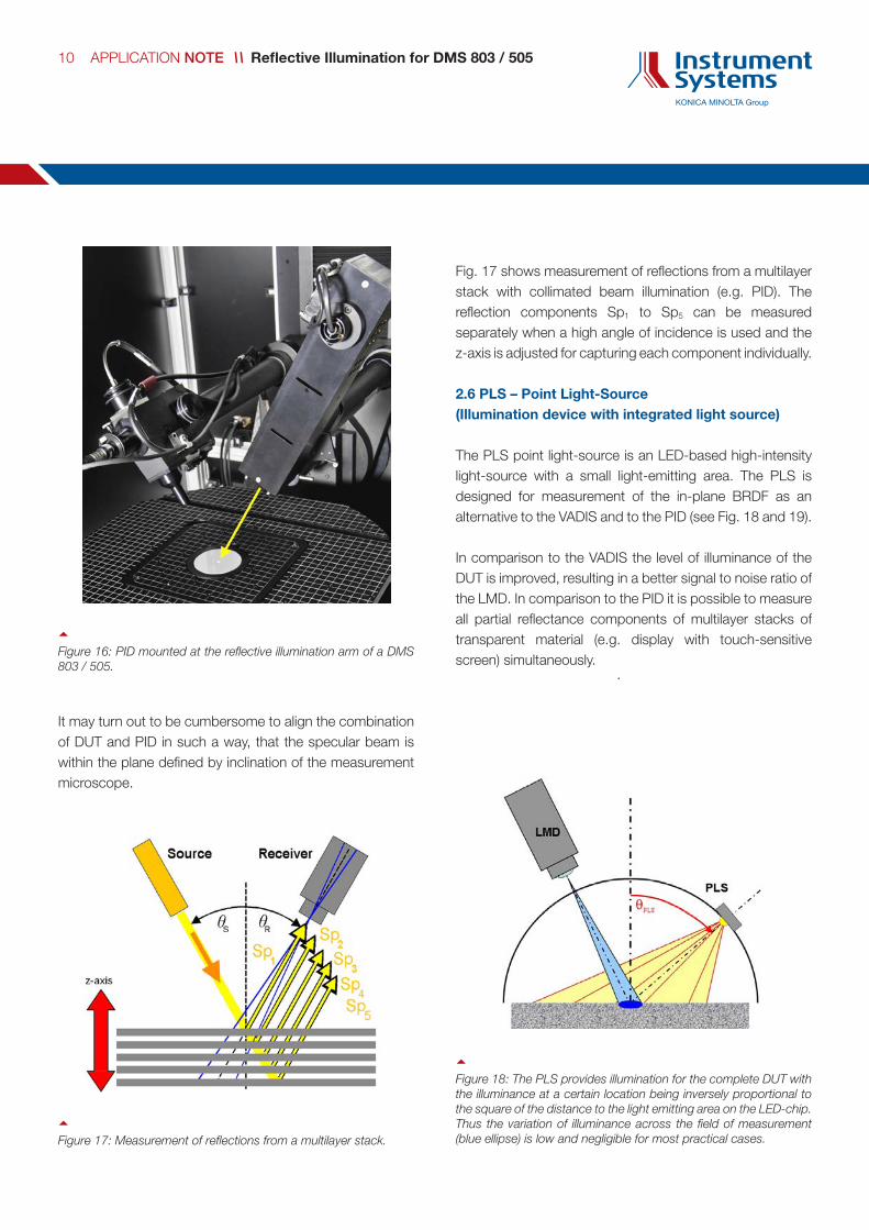
It may turn out to be cumbersome to align the combination of DUT and PID in such a way, that the specular beam is within the plane defined by inclination of the measurement microscope.
Fig. 17 shows measurement of reflections from a multilayer stack with collimated beam illumination (e.g. PID). The reflection components Sp1 to Sp5 can be measured separately when a high angle of incidence is used and the z-axis is adjusted for capturing each component individually.
2.6 PLS – Point Light-Source (Illumination device with integrated light source)
The PLS point light-source is an LED-based high-intensity light-source with a small light-emitting area. The PLS is designed for measurement of the in-plane BRDF as an alternative to the VADIS and to the PID (see Fig. 18 and 19).
In comparison to the VADIS the level of illuminance of the DUT is improved, resulting in a better signal to noise ratio of the LMD. In comparison to the PID it is possible to measure all partial reflectance components of multilayer stacks of transparent material (e.g. display with touch-sensitive screen) simultaneously.
10 APPLICATION NOTE // Reflective Illumination for DMS 803 / 505
~Figure 16: PID mounted at the reflective illumination arm of a DMS 803 / 505.
~Figure 17: Measurement of reflections from a multilayer stack.
~Figure 18: The PLS provides illumination for the complete DUT with the illuminance at a certain location being inversely proportional to the square of the distance to the light emitting area on the LED-chip. Thus the variation of illuminance across the field of measurement (blue ellipse) is low and negligible for most practical cases.
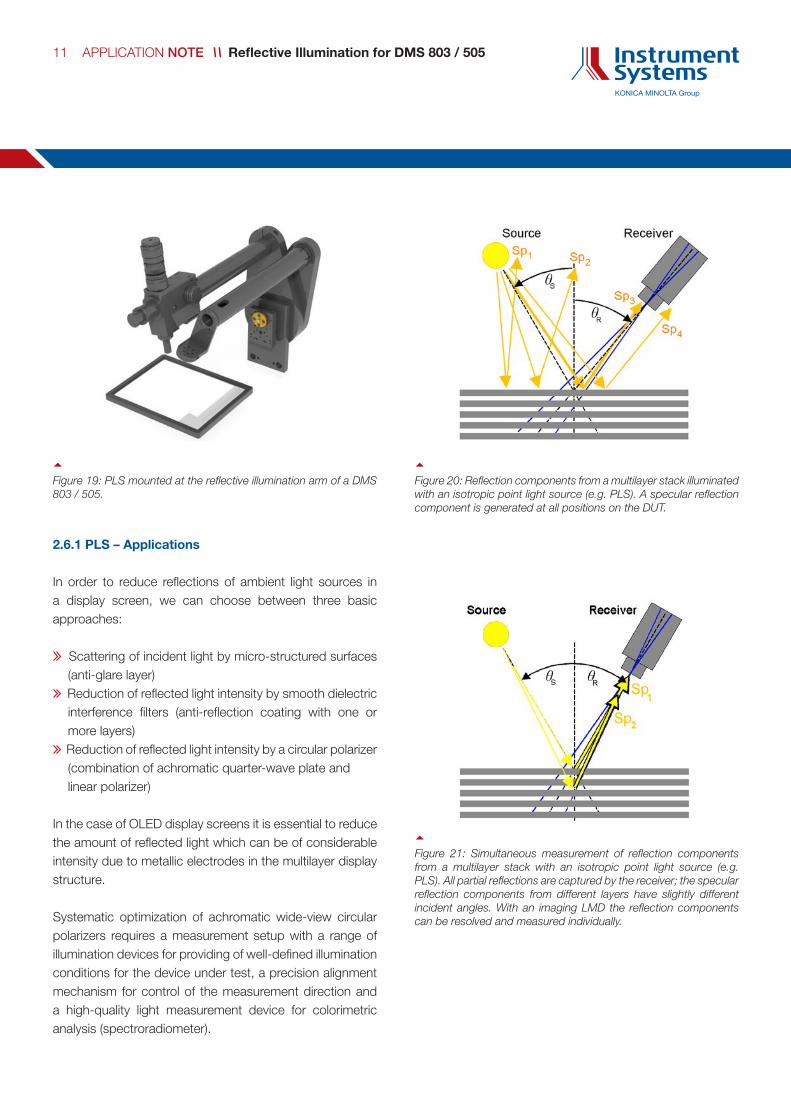
2.6.1 PLS – Applications
In order to reduce reflections of ambient light sources in a display screen, we can choose between three basic approaches:
Scattering of incident light by micro-structured surfaces (anti-glare layer)
Reduction of reflected light intensity by smooth dielectric interference filters (anti-reflection coating with one or more layers)
Reduction of reflected light intensity by a circular polarizer (combination of achromatic quarter-wave plate and linear polarizer)
In the case of OLED display screens it is essential to reduce the amount of reflected light which can be of considerable intensity due to metallic electrodes in the multilayer display structure.
Systematic optimization of achromatic wide-view circular polarizers requires a measurement setup with a range of illumination devices for providing of well-defined illumination conditions for the device under test, a precision alignment mechanism for control of the measurement direction and a high-quality light measurement device for colorimetric analysis (spectroradiometer).
11 APPLICATION NOTE // Reflective Illumination for DMS 803 / 505
~Figure 19: PLS mounted at the reflective illumination arm of a DMS 803 / 505.
~Figure 20: Reflection components from a multilayer stack illuminated with an isotropic point light source (e.g. PLS). A specular reflection component is generated at all positions on the DUT.
~Figure 21: Simultaneous measurement of reflection components from a multilayer stack with an isotropic point light source (e.g. PLS). All partial reflections are captured by the receiver; the specular reflection components from different layers have slightly different incident angles. With an imaging LMD the reflection components can be resolved and measured individually.

2.6.2 PLS – Illumination geometries
When directional illumination is used for analysis of the spectral distribution of sample reflectance, e.g. provided by PLS, VADIS or PID, the variation of both reflected luminance and chromaticity can be evaluated as a function of the azimuth angle for one constant angle of inclination of light incidence.
When multi-directional illumination is used in order to take into account light illuminating the sample from all directions in the hemisphere, the DHS can be used to approximate this situation (illumination up to inclinations of 70°) with specular components excluded or included, depending on the intention of the analysis.
In both cases, the illumination is measured in the first step with one of the following approaches:
Via a diffuse white reflectance standard (with calibrated reflectance vs. wavelength of light when only the spectrum of illumination matters)
Via a calibrated specular mirror (polished black glass or metallic surface mirror)
Measurement of the light source spectral radiance directly (possible with PLS and VADIS)
All subsequent sample measurements are then referred to this source spectrum, so only the spectrum of sample reflectance is obtained.
Since these measurements do not require absolute radiance measurements, the accuracy of the measurement is only depending on LMD linearity, dynamical range and wavelength calibration. High quality measurements are thus assured.
During evaluation of the measurement data in the DMS ViPer software, arbitrary measured or tabulated spectra can be added to the reflectance spectra (by multiplication) in order to take into account arbitrary illumination sources and illuminants (e.g. D65). The comprehensive evaluation software module for DMS measurement data (ViPer)
provides a wide range of evaluations and graphical representations according to the customers’ requirements.
12 APPLICATION NOTE // Reflective Illumination for DMS 803 / 505
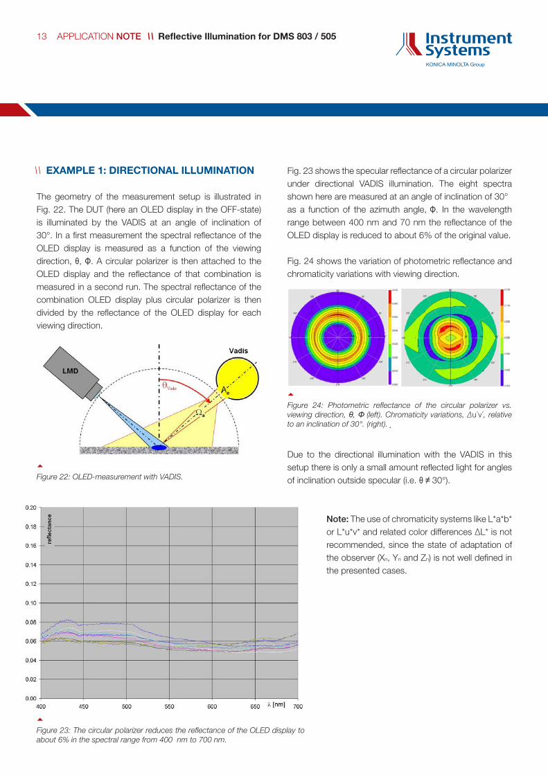
// EXAMPLE 1: DIRECTIONAL ILLUMINATION
The geometry of the measurement setup is illustrated in Fig. 22. The DUT (here an OLED display in the OFF-state) is illuminated by the VADIS at an angle of inclination of 30°. In a first measurement the spectral reflectance of the OLED display is measured as a function of the viewing direction, θ, Φ. A circular polarizer is then attached to the OLED display and the reflectance of that combination is measured in a second run. The spectral reflectance of the combination OLED display plus circular polarizer is then divided by the reflectance of the OLED display for each viewing direction.
Fig. 23 shows the specular reflectance of a circular polarizer under directional VADIS illumination. The eight spectra shown here are measured at an angle of inclination of 30° as a function of the azimuth angle, Φ. In the wavelength range between 400 nm and 70 nm the reflectance of the OLED display is reduced to about 6% of the original value.
Fig. 24 shows the variation of photometric reflectance and chromaticity variations with viewing direction.
Due to the directional illumination with the VADIS in this setup there is only a small amount reflected light for angles of inclination outside specular (i.e. θ ≠ 30°).
~Figure 22: OLED-measurement with VADIS.
~Figure 23: The circular polarizer reduces the reflectance of the OLED display to about 6% in the spectral range from 400 nm to 700 nm.
13 APPLICATION NOTE // Reflective Illumination for DMS 803 / 505
~Figure 24: Photometric reflectance of the circular polarizer vs. viewing direction, θ, Φ (left). Chromaticity variations, ∆u´v´, relative to an inclination of 30°. (right).
Note: The use of chromaticity systems like L*a*b* or L*u*v* and related color differences ∆L* is not recommended, since the state of adaptation of the observer (Xn, Yn and Zn) is not well defined in the presented cases.

// EXAMPLE 2: MULTIDIRECTIONAL ILLUMINATION
The sample is illuminated by the DHS up to an angle of inclination of 70° with specular components excluded by the north-polar slit in the hemisphere.
An aluminum reflector with a rough scattering surface is used for measurement of the spectral distribution of illumination. The reflectance of the sample (circular polarizer) is evaluated with respect to this spectral distribution of reflected radiance.
Fig. 25 illustrates the spectral distribution of circular polarizer reflectance as a function of direction of measurement, θ, Φ, together with the corresponding chromaticity coordinates, u´v´ CIE 1976.
Fig. 26 shows variation of photometric reflectance and chromaticity variations with viewing direction. In this case the chromaticity difference, ∆u'v' exhibts considerable variations with both angle of inclination and azimuth angle.
14 APPLICATION NOTE // Reflective Illumination for DMS 803 / 505
~Figure 25: Specular reflectance of a circular polarizer under multidirectional DHS illumination together with the corresponding chromaticities, u´v´ CIE 1976. The spectra shown here are measured for angles of inclination between 0° and 60° as a function of the azimuth angle, Φ. In the wavelength range between 400 nm and 70 nm the reflectance of the OLED display is reduced to about 6% of the original value.
~Figure 26: Photometric reflectance of the circular polarizer vs. viewing direction (left). Chromaticity variations, ∆u'v', relative to an inclination of 0° (right).
Note: The use of chromaticity systems like L*a*b* or L*u*v* and related color differences ∆L* is not recommended, since the state of adaptation of the observer (Xn, Yn and Zn) is not well defined in the presented cases.

Instrument Systems GmbH Kastenbauerstr. 2 81677 Munich, Germany
ph: +49 (0)89 45 49 43-58 fax: +49 (0)89 45 49 43-11 [email protected] www.instrumentsystems.com
We bring quality to light.
an_i
llum
inat
ion
for
DM
S_e
n_V
1.1