application note / datasheet preciseloop magnetic loop...
TRANSCRIPT
THE PeciseLOOP® MAGNETIC LOOP ANTENNA (MLA)Roger Stenbock W1RMS September 12, 2017
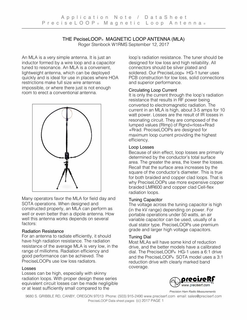
An MLA is a very simple antenna. It is just an inductor formed by a wire loop and a capacitor tuned to resonance. An MLA is a convenient, lightweight antenna, which can be deployed quickly and is ideal for use in places where HOA restrictions make full size wire antennas impossible, or where there just is not enough room to erect a conventional antenna.
Many operators favor the MLA for field day and SOTA operations. When designed and constructed properly, an MLA can perform as well or even better than a dipole antenna. How well this antenna works depends on several factors: Radiation ResistanceFor an antenna to radiate efficiently, it should have high radiation resistance. The radiation resistance of the average MLA is very low, in the range of milliohms. Radiation efficiency and good performance can be achieved. The PreciseLOOPs use low loss radiators.LossesLosses can be high, especially with skinny radiation loops. With proper design these series equivalent circuit losses can be made negligible or at least sufficiently small compared to the
loop’s radiation resistance. The tuner should be designed for low loss and high reliability. All connectors should be silver plated and soldered. Our PreciseLoop® HG-1 tuner uses PCB construction for low loss, solid connections and superior performance.Circulating Loop CurrentIt is only the current through the loop’s radiation resistance that results in RF power being converted to electromagnetic radiation. The current in an MLA is high, about 3-5 amps for 10 watt power. Losses are the result of IR losses in resonating circuit. They are composed of the lumped values (Rlmp) of Rgnd+rloss+Rrad+Rrad. PreciseLOOPs are designed for maximum loop current providing the highest efficiency. Loop LossesBecause of skin effect, loop losses are primarily determined by the conductor’s total surface area. The greater the area, the lower the losses. Recall that the surface area increases by the square of the conductor’s diameter. This is true for both braided and copper clad loops. That is why PreciseLOOPs use more expensive copper braided LMR600 and copper clad Cell-flex radiation loops. Tuning CapacitorThe voltage across the tuning capacitor is high (in the kV range) depending on power. For portable operations under 50 watts, an air variable capacitor can be used, usually of a dual stator type. PreciseLOOPs use premium grade and larger high voltage capacitors. Tuning DialMost MLAs will have some kind of reduction drive, and the better models have a calibrated dial. The PreciseLOOP® HG-1 uses a 6:1 drive and the PreciseLOOP® SOTA model uses a 3:1 reduction drive with clearly marked band coverage.
A p p l i c a t i o n N o t e / D a t a S h e e tP r e c i s e L O O P ® M a g n e t i c L o o p A n t e n n a ®
9680 S. GRIBBLE RD, CANBY, OREGON 97013 Phone: (503) 915-2490 www.preciserf.com email: [email protected] PreciseLOOP Data sheet.pages (c) 2017 PAGE 1
Precision Ham Radio Measurements

Receiver Mode AdvangeThe high-Q resonator imparts a very narrow band frequency selective bandpass filter ahead of the Rx front-end stages. Such an incidental preselector comprising the antenna itself imparts greatly improved receiver performance on the congested lower HF bands with high power broadcast stations and particularly when lightning strikes and atmospheric electrical discharges are present in the regional area.
Gain ParametersThe MLA with its doughnut shaped radiation pattern exhibits a typical gain of 1.5 dBi over average ground and a gain of 5 dBi when deployed with either short radials (the length of each radial need only be twice the loop diameter) or mounted over a conductive ground plane surface. The front to side ratio of a loop is typically 20 to 25 dB.
Fig.1 PreciseLOOP radiation vertical plane
In comparison a large ½ λ horizontal dipole mounted ¼ λ above average ground has a gain of 5.12 dBi, and a ¼ λ Vertical, with 120 radials each ¼ λ long, has a gain of 2 dBi over average ground.
Fig.2 Dipole radiation at 40’ vertical plane
Gain v. DipoleAn MLA is usually deployed under portable operations such as field day and Summit On The Air (SOTA). In these applications the questions arrises how does the MLA compare to a dipole erected at lower levels. Since the dipole’s takeoff angle is considerably higher, an MLA can outperform a low dipole by as much as 6 dB at the lower takeoff angles for DX use.
Fig. 3 Gain of MLA (blue) v. low dipole (red) at 15’
A p p l i c a t i o n N o t e / D a t a S h e e tP r e c i s e L O O P ® M a g n e t i c L o o p A n t e n n a ®
9680 S. GRIBBLE RD, CANBY, OREGON 97013 Phone: (503) 915-2490 www.preciserf.com email: [email protected] PreciseLOOP Data sheet.pages (c) 2017 PAGE 2
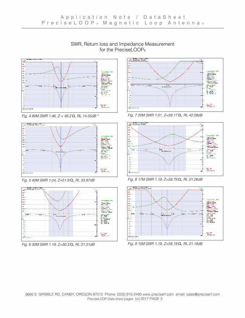
SWR, Return loss and Impedance Measurement for the PreciseLOOP®
Fig. 4 80M SWR 1.46, Z = 48.2 Ω, RL 14.55dB *
Fig. 5 40M SWR 1.04, Z=51.9 Ω, RL 33.97dB
Fig. 6 30M SWR 1.19, Z=50.3 Ω, RL 21.31dB
Fig. 7 20M SWR 1.01, Z=59.17 Ω, RL 42.09dB
Fig. 8 17M SWR 1.19, Z=58.79 Ω, RL 21.26dB
Fig. 9 15M SWR 1.19, Z=58.19 Ω, RL 21.18dB
A p p l i c a t i o n N o t e / D a t a S h e e tP r e c i s e L O O P ® M a g n e t i c L o o p A n t e n n a ®
9680 S. GRIBBLE RD, CANBY, OREGON 97013 Phone: (503) 915-2490 www.preciserf.com email: [email protected] PreciseLOOP Data sheet.pages (c) 2017 PAGE 3

Fig. 10 12M SWR 1.07, Z=51.00 Ω, RL 28.86dB
Fig. 11 10M SWR 1.14, Z=56.85 Ω, RL 23.40dB
Fig. 12 Induction loop sensitivity, vertical position +/- 1/4”
Measurements taken with an Array Solutions VNA-UHF two port Vector Network Analyzer, 4 kHz to 1200 MHz
Fig. 13 Vector Network Analyzer
Current Measurements
Fig. 14 MFJ RF Clamp-on current meter.
EZNEC is a great simulation tool, but it only provide a starting point. Whenever possible, I back-up the simulations with actual measurements. Short of an antenna range, the loop current is the most reliable way to check loop performance. While not a lab grade instrument, the MFJ-853 is a good tool for this measurement. It was calibrated agains a NIST traceable lab RF current probe and calibrated to be accurate to 5%.
In Fig. 14 at left, the meter is indicating 100% of full scale in the 3A position. The clamp disturbance is negligible. VSWR variations were minuscule with the clamped on meter. In all measurements, maximum current was observed at minimum VSWR. I tested a number of loop diameters ranging from 3/8” to 1/2” “hard line (Cell-flex) and LMR600. There was no observable difference between braided and solid coper shielding. The most significant differences was attributed to loop surface area. The test correlated well with SWR Rlmp of Rgnd+Rloss+Rrad+Rrad and power measurements.
A p p l i c a t i o n N o t e / D a t a S h e e tP r e c i s e L O O P ® M a g n e t i c L o o p A n t e n n a ®
9680 S. GRIBBLE RD, CANBY, OREGON 97013 Phone: (503) 915-2490 www.preciserf.com email: [email protected] PreciseLOOP Data sheet.pages (c) 2017 PAGE 4
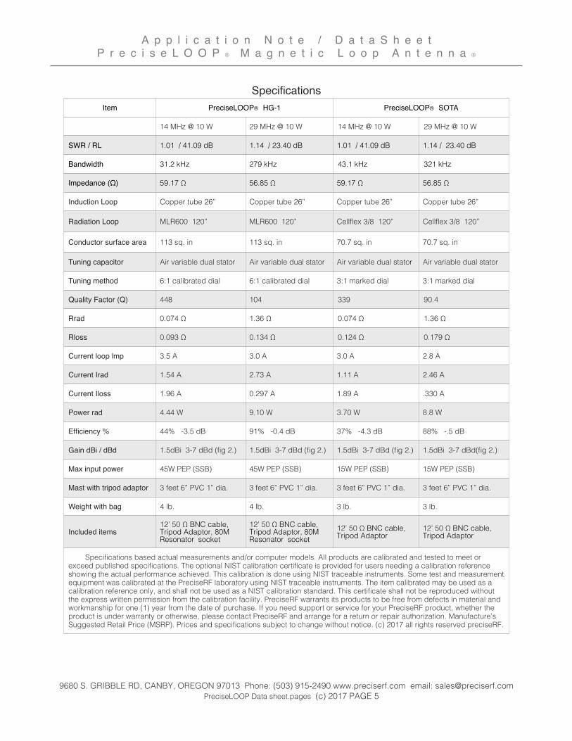
SpecificationsItem PreciseLOOP® HG-1PreciseLOOP® HG-1 PreciseLOOP® SOTAPreciseLOOP® SOTA
14 MHz @ 10 W 29 MHz @ 10 W 14 MHz @ 10 W 29 MHz @ 10 W
SWR / RL 1.01 / 41.09 dB 1.14 / 23.40 dB 1.01 / 41.09 dB 1.14 / 23.40 dB
Bandwidth 31.2 kHz 279 kHz 43.1 kHz 321 kHz
Impedance (Ω) 59.17 Ω 56.85 Ω 59.17 Ω 56.85 Ω
Induction Loop Copper tube 26” Copper tube 26” Copper tube 26” Copper tube 26”
Radiation Loop MLR600 120” MLR600 120” Cellflex 3/8 120” Cellflex 3/8 120”
Conductor surface area 113 sq. in 113 sq. in 70.7 sq. in 70.7 sq. in
Tuning capacitor Air variable dual stator Air variable dual stator Air variable dual stator Air variable dual stator
Tuning method 6:1 calibrated dial 6:1 calibrated dial 3:1 marked dial 3:1 marked dial
Quality Factor (Q) 448 104 339 90.4
Rrad 0.074 Ω 1.36 Ω 0.074 Ω 1.36 Ω
Rloss 0.093 Ω 0.134 Ω 0.124 Ω 0.179 Ω
Current loop lmp 3.5 A 3.0 A 3.0 A 2.8 A
Current Irad 1.54 A 2.73 A 1.11 A 2.46 A
Current Iloss 1.96 A 0.297 A 1.89 A .330 A
Power rad 4.44 W 9.10 W 3.70 W 8.8 W
Efficiency % 44% -3.5 dB 91% -0.4 dB 37% -4.3 dB 88% -.5 dB
Gain dBi / dBd 1.5dBi 3-7 dBd (fig 2.) 1.5dBi 3-7 dBd (fig 2.) 1.5dBi 3-7 dBd (fig 2.) 1.5dBi 3-7 dBd(fig 2.)
Max input power 45W PEP (SSB) 45W PEP (SSB) 15W PEP (SSB) 15W PEP (SSB)
Mast with tripod adaptor 3 feet 6” PVC 1” dia. 3 feet 6” PVC 1” dia. 3 feet 6” PVC 1” dia. 3 feet 6” PVC 1” dia.
Weight with bag 4 lb. 4 lb. 3 lb. 3 lb.
Included items12’ 50 Ω BNC cable, Tripod Adaptor, 80M Resonator socket
12’ 50 Ω BNC cable, Tripod Adaptor, 80M Resonator socket
12’ 50 Ω BNC cable, Tripod Adaptor
12’ 50 Ω BNC cable, Tripod Adaptor
Specifications based actual measurements and/or computer models. All products are calibrated and tested to meet or exceed published specifications. The optional NIST calibration certificate is provided for users needing a calibration reference showing the actual performance achieved. This calibration is done using NIST traceable instruments. Some test and measurement equipment was calibrated at the PreciseRF laboratory using NIST traceable instruments. The item calibrated may be used as a calibration reference only, and shall not be used as a NIST calibration standard. This certificate shall not be reproduced without the express written permission from the calibration facility. PreciseRF warrants its products to be free from defects in material and workmanship for one (1) year from the date of purchase. If you need support or service for your PreciseRF product, whether the product is under warranty or otherwise, please contact PreciseRF and arrange for a return or repair authorization. Manufacture’s Suggested Retail Price (MSRP). Prices and specifications subject to change without notice. (c) 2017 all rights reserved preciseRF.
Specifications based actual measurements and/or computer models. All products are calibrated and tested to meet or exceed published specifications. The optional NIST calibration certificate is provided for users needing a calibration reference showing the actual performance achieved. This calibration is done using NIST traceable instruments. Some test and measurement equipment was calibrated at the PreciseRF laboratory using NIST traceable instruments. The item calibrated may be used as a calibration reference only, and shall not be used as a NIST calibration standard. This certificate shall not be reproduced without the express written permission from the calibration facility. PreciseRF warrants its products to be free from defects in material and workmanship for one (1) year from the date of purchase. If you need support or service for your PreciseRF product, whether the product is under warranty or otherwise, please contact PreciseRF and arrange for a return or repair authorization. Manufacture’s Suggested Retail Price (MSRP). Prices and specifications subject to change without notice. (c) 2017 all rights reserved preciseRF.
Specifications based actual measurements and/or computer models. All products are calibrated and tested to meet or exceed published specifications. The optional NIST calibration certificate is provided for users needing a calibration reference showing the actual performance achieved. This calibration is done using NIST traceable instruments. Some test and measurement equipment was calibrated at the PreciseRF laboratory using NIST traceable instruments. The item calibrated may be used as a calibration reference only, and shall not be used as a NIST calibration standard. This certificate shall not be reproduced without the express written permission from the calibration facility. PreciseRF warrants its products to be free from defects in material and workmanship for one (1) year from the date of purchase. If you need support or service for your PreciseRF product, whether the product is under warranty or otherwise, please contact PreciseRF and arrange for a return or repair authorization. Manufacture’s Suggested Retail Price (MSRP). Prices and specifications subject to change without notice. (c) 2017 all rights reserved preciseRF.
Specifications based actual measurements and/or computer models. All products are calibrated and tested to meet or exceed published specifications. The optional NIST calibration certificate is provided for users needing a calibration reference showing the actual performance achieved. This calibration is done using NIST traceable instruments. Some test and measurement equipment was calibrated at the PreciseRF laboratory using NIST traceable instruments. The item calibrated may be used as a calibration reference only, and shall not be used as a NIST calibration standard. This certificate shall not be reproduced without the express written permission from the calibration facility. PreciseRF warrants its products to be free from defects in material and workmanship for one (1) year from the date of purchase. If you need support or service for your PreciseRF product, whether the product is under warranty or otherwise, please contact PreciseRF and arrange for a return or repair authorization. Manufacture’s Suggested Retail Price (MSRP). Prices and specifications subject to change without notice. (c) 2017 all rights reserved preciseRF.
Specifications based actual measurements and/or computer models. All products are calibrated and tested to meet or exceed published specifications. The optional NIST calibration certificate is provided for users needing a calibration reference showing the actual performance achieved. This calibration is done using NIST traceable instruments. Some test and measurement equipment was calibrated at the PreciseRF laboratory using NIST traceable instruments. The item calibrated may be used as a calibration reference only, and shall not be used as a NIST calibration standard. This certificate shall not be reproduced without the express written permission from the calibration facility. PreciseRF warrants its products to be free from defects in material and workmanship for one (1) year from the date of purchase. If you need support or service for your PreciseRF product, whether the product is under warranty or otherwise, please contact PreciseRF and arrange for a return or repair authorization. Manufacture’s Suggested Retail Price (MSRP). Prices and specifications subject to change without notice. (c) 2017 all rights reserved preciseRF.
A p p l i c a t i o n N o t e / D a t a S h e e tP r e c i s e L O O P ® M a g n e t i c L o o p A n t e n n a ®
9680 S. GRIBBLE RD, CANBY, OREGON 97013 Phone: (503) 915-2490 www.preciserf.com email: [email protected] PreciseLOOP Data sheet.pages (c) 2017 PAGE 5
Deploying the PreciseLOOP® Antenna
The PreciseLOOP® is designed for quick deployment. Everything you need is included in the handy premium bag. The process takes under five minutes.
Assembly1. Find a level surface that is clear of any obstructions within approximately 15 foot radius. Extend your
tripod to a convenient height. The PreciseLOOP® will work well from two feet or higher above the ground.
2. Assemble the antenna mast. It consists of three sections. The lower section contains the tuner, the center section connects the lower and the top section and the top section contains the induction loop. All it takes is slight pressure to fit the mast sections securely together. Attach the included tripod adaptor to the antenna mast.
3. Attach the tuner to the lower mast section using the supplied bolts. Mount the mast to the tripod’s standard 25 mm socket.
4. Spread the radiation loop and fit to the top of the mast. Make sure the loop element is facing toward the front over the induction loop. Securely attached PL239 connectors to the tuner inputs.
5. Connect the 12 foot, 50 ohm BNC cable, from the induction loop output the transceivers antenna input. Adjust the loop assembly for a symmetrical appearance.
Tuning
1. Tuning instructions are also printed on the tuning enclosure, refer to them as well.
2. Select the band you wish to use. Set the transceiver to SSB (this provides the loudest background noise).
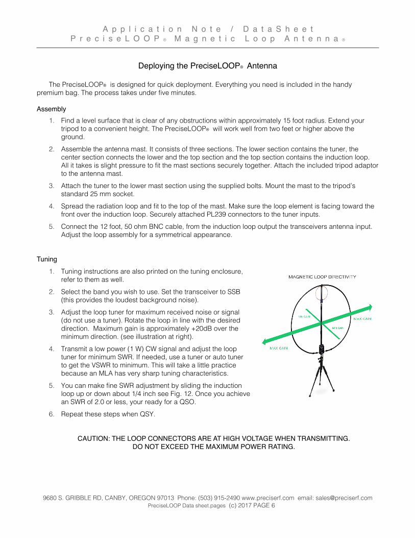
3. Adjust the loop tuner for maximum received noise or signal (do not use a tuner). Rotate the loop in line with the desired direction. Maximum gain is approximately +20dB over the minimum direction. (see illustration at right).
4. Transmit a low power (1 W) CW signal and adjust the loop tuner for minimum SWR. If needed, use a tuner or auto tuner to get the VSWR to minimum. This will take a little practice because an MLA has very sharp tuning characteristics.
5. You can make fine SWR adjustment by sliding the induction loop up or down about 1/4 inch see Fig. 12. Once you achieve an SWR of 2.0 or less, your ready for a QSO.
6. Repeat these steps when QSY.
CAUTION: THE LOOP CONNECTORS ARE AT HIGH VOLTAGE WHEN TRANSMITTING. DO NOT EXCEED THE MAXIMUM POWER RATING.
A p p l i c a t i o n N o t e / D a t a S h e e tP r e c i s e L O O P ® M a g n e t i c L o o p A n t e n n a ®
9680 S. GRIBBLE RD, CANBY, OREGON 97013 Phone: (503) 915-2490 www.preciserf.com email: [email protected] PreciseLOOP Data sheet.pages (c) 2017 PAGE 6
Information on the Internet
Not withstanding the useful information available from the ARRL, engineers and hams such as Leigh Turner VK5KLT, who in his excellent article wrote “It seems one of the best kept secrets in the amateur radio community is how well a small diminutive magnetic loop antenna can really perform in practice compared with large traditional HF antennas”, there still are a few nay-sayers who fail to appreciate the MLA.
Julian OH8STN, a retired broadcast engineer, in part, puts it this way. “These days it seems like everyone is attacking the very popular, small, lightweight, and extremely portable, magnetic loop antenna (MLA). Lately there’s been a few forum threads, blog posts, and video comments, reportedly comparing the performance differences between a magnetic loop antenna and dipole antenna in various deployment scenarios. For the most part, these comparisons are absolutely valid and well meaning. Unfortunately, there are those instances, when comparisons present a very one sided view, leaving much to be desired. Often the “comparisons” only focus on the 40 meter amateur radio band.”
As did this “expert” who fancies having a superior grasp of mathematics and NEC modeling skills. In a review of a new MLA, without hands on the product, he based MLA efficiency primarily from VSWR & bandwidth data using his model. (However, when his model was compared to measurements, loop current was not given, and MLA dBi gain did not agree with the accepted values). He then opined the published gain was an obfuscation. Those who disagree with him have their work belittled as “appeals to the innumerate.”
ARRL technical editor, Jerry Hall K1TD, in describing MLS gain concluded “in fact it (MLA) considerably exceeds the gain of a dipole when the MLA is mounted close to the ground, the gain increases to 8.16 dBi for a perfect ground (for 20M to 10M band) Jul 1985 QST.
Julian continues...”Small portable loops are at a distinct disadvantage on 40, 60, & 80 meters, in comparison to a full size antenna. Everyone knows this, but none of the tests or comparisons will ever show you 30, 20, 17, 15, 12 or 10 meters because the test results, would no longer be as “clear”. Loop performance (efficiency) increases as we head higher up the band. So much so, that a dipole and MLA could be indistinguishable on higher band results. In fact, it actually becomes an outright fair fight! Focusing solely on the 40 meter band is not a lie, it’s just doesn’t tell us the whole truth ... these comparisons usually ignore the larger diameter magnetic loops as add-ons, multi-turn loops, and larger “less portable” loops, since doing so would completely debunk the results as presented in these tests. So their focus is usually the less efficient, but very much smaller, more portable, lightweight and easy to deploy little brothers. For example, MLAs like the Chameleon P-Loop, F-Loop in their default configuration, AlexLoop, [PreciseLOOP] and so on.
So let’s point out for the record that operators don’t usually build or buy small portable magnetic loops for their excellent performance on 40 meters. They use these systems because of their portability and very small deployment footprint. In a way, these comparisons are as ridiculous as saying “lets test a dipole versus a small magnetic in my kitchen.”
73’Roger W1RMS
A p p l i c a t i o n N o t e / D a t a S h e e tP r e c i s e L O O P ® M a g n e t i c L o o p A n t e n n a ®
9680 S. GRIBBLE RD, CANBY, OREGON 97013 Phone: (503) 915-2490 www.preciserf.com email: [email protected] PreciseLOOP Data sheet.pages (c) 2017 PAGE 7
Precision Ham Radio Measurements