application note of w-cdma/gsm measurements · revision history ver. no date contents related...
TRANSCRIPT
Revision History
Ver. No
Date Contents Related product software version
1.00 May 2015 MT8820B/20C/21C W/G Application Note (Ver 1.00) succeeded MT8820B/20C W/G Application Note (Ver 6.00) Overall: Changed model name from MT8820B/C to “equipment” Overall: Added MT8821C option model names to MT8820B/C option model names Added MT8821C software specification Changed 1.10 CALIBRATION and 2.13 CALIBRATION to refer to the application note for UE Calibration.
MX882000C Ver23.20 MX882001C Ver23.03 MX882100C Ver30.00 MX882101C Ver30.00
1.01 Jan 2016 Corrected error in red box in figure MX882000C Ver23.30
MX882001C Ver23.04
MX882100C Ver30.13
MX882101C Ver30.13 2.00 Jun 2016 Added the judgment procedure using 3GPP TS51.010-1
measurement procedure to 2.3.7 Output RF spectrum Added the judgment procedure using 3GPP TS51.010-1 measurement procedure to 2.5.5 Output RF spectrum in GPRS multislot configuration. Added the judgment procedure using 3GPP TS51.010-1 measurement procedure to 2.8.5Output RF spectrum
MX882000C Ver23.30
MX882001C Ver23.04
MX882100C Ver30.32
MX882101C Ver30.32
W-CDMA/GSM Measurement Radio Communication Analyzer MT8820B/MT8820C/MT8821C

Contents 1. W-CDMA Measurement Software ..................................................................................... 7
1.1. SPECIFICATIONS ...................................................................................................................................... 7 1.1.1. MT8820B/20C software specification .......................................................................................... 7 1.1.2. MT8821C Specification ................................................................................................................ 13
1.2. 3GPP MEASUREMENT SPECIFICATION TABLE ......................................................................................... 19 1.2.1. MX882000C/MX882100C - MT8820B/20C/21C W-CDMA Measurement Software ................. 19 1.2.2. W-CDMA Bands ............................................................................................................................ 22
1.3. TRX MEASUREMENT (FUNDAMENTAL MEASUREMENT) ........................................................................... 23 1.3.1. Connection with Test Loop Mode .............................................................................................. 23 1.3.2. Disconnection with Test Loop Mode .......................................................................................... 23 1.3.3. Channel Switching using Handover ........................................................................................... 23 1.3.4. Selecting Test Items .................................................................................................................... 23 1.3.5. 5.2 Maximum Output Power ...................................................................................................... 24 1.3.6. 5.3 Frequency Error ..................................................................................................................... 24 1.3.7. 5.7 Power setting in uplink compressed mode ........................................................................ 25 1.3.8. 5.8 Occupied Bandwidth ............................................................................................................. 27 1.3.9. 5.9 Spectrum Emission Mask ...................................................................................................... 27 1.3.10. 5.10 Adjacent Channel Leakage Power ................................................................................... 28 1.3.11. 5.13.1 Error Vector Magnitude (EVM) ...................................................................................... 29 1.3.12. 6.2 Reference Sensitivity Level ................................................................................................. 29 1.3.13. Measurement Time Reduction using Batch Process .............................................................. 30 1.3.14. 5.4.3 Minimum Output Power .................................................................................................. 30
1.4. OPEN LOOP POWER CONTROL MEASUREMENT ...................................................................................... 31 1.4.1. 5.4.1 Open Loop Power Control in Uplink (RX-middle) ............................................................ 31 1.4.2. 5.4.1 Open Loop Power Control in Uplink (RX Upper dynamic end) ....................................... 32 1.4.3. 5.4.1 Open Loop Power Control in Uplink (RX-Sensitivity level) .............................................. 33 1.4.4. 5.5 Transmit ON/OFF Power ....................................................................................................... 34 1.4.5. 5.13.4 PRACH Preamble Quality ................................................................................................. 36 1.4.6. Continuous Measurement of Open Loop Power Control ........................................................ 36
1.5. INNER LOOP POWER CONTROL MEASUREMENT ...................................................................................... 37 1.5.1. 5.4.2 Inner Loop Power Control in the Uplink .......................................................................... 37 1.5.2. 5.13.3 UE Phase Discontinuity .................................................................................................... 38
1.6. OTHER MEASUREMENTS ........................................................................................................................ 43 1.6.1. 5.4.4 Out-of-synchronization of output power. 5.4.4AOut-of-synchronization handling of
output power for a UE which supports type1 for DCH............................................................ 43 1.6.2. 5.4.4 Out-of-synchronisation of output power (Auto) 5.4.4AOut-of-synchronization
handling of output power for a UE which supports type1 for DCH ....................................... 46 1.6.3. 5.6 Change of TFC ........................................................................................................................ 48 1.6.4. 6.3 Maximum Input Level ........................................................................................................... 49 1.6.5. 6.8 Spurious Emissions ............................................................................................................... 49 1.6.6. 7.2 Demodulation in Static Propagation Condition .................................................................. 50
1.7. REDUCTION OF W-CDMA/GSM MEASUREMENT TIME BY INTER-RAT HANDOVER ................................... 51 1.8. UE REPORT .......................................................................................................................................... 52 1.9. FUNCTIONAL TEST ................................................................................................................................. 53
1.9.1. Voice Call ...................................................................................................................................... 53
2
1.9.2. External Packet Data ................................................................................................................... 54 1.9.3. Videophone .................................................................................................................................. 58
1.10. CALIBRATION MEASUREMENT FUNCTION .............................................................................................. 60 1.11. HSDPA MEASUREMENT ....................................................................................................................... 61
1.11.1. Location Registration of Fixed Reference Channel ................................................................ 61 1.11.2. Connection of Fixed Reference Channel ................................................................................. 61 1.11.3. Disconnection of Fixed Reference Channel ............................................................................ 61 1.11.4. Channel Change by Handover ................................................................................................. 61 1.11.5. Change of Tβc, βd by Transport Channel Reconfiguration .................................................... 62 1.11.6. Selection of Measurement Items ............................................................................................. 62 1.11.7. 5.2A Maximum Output Power with HS-DPCCH (Release 5 only) 5.2AA Maximum
Output Power with HS-DPCCH (Release 6 and later) ............................................................... 63 1.11.8. 5.2C UE Relative Code Domain Power Accuracy (Release 6 and later) ............................. 65 1.11.9. 5.7A HS-DPCCH Power Control................................................................................................. 71 1.11.10. 5.9A Spectrum Emission Mask with HS-DPCCH .................................................................... 76 1.11.11. 5.10A Adjacent Channel Leakage Power Ratio (ACLR) with HS-DPCCH .............................. 77 1.11.12. 5.13.1A Error Vector Magnitude (EVM) with HS-DPCCH 5.13.1AA Error Vector Magnitude
(EVM) and Phase Discontinuity with HS-DPCCH ....................................................................... 79 1.11.13. 5.13.2A Relative Code Domain Error with HS-DPCCH .......................................................... 82 1.11.14. 6.3A Maximum Input Level for HS-PDSCH Reception (16QAM) .......................................... 86
1.12. HSUPA MEASUREMENT ...................................................................................................................... 87 1.12.1. E-DCH RF Test Location Registration ....................................................................................... 87 1.12.2. E-DCH RF Test Connection ........................................................................................................ 87 1.12.3. E-DCH RF Test Disconnection ................................................................................................... 87 1.12.4. Channel Change at Handover .................................................................................................. 87 1.12.5. Change of βc and βd by Transport Channel Reconfiguration ............................................... 88 1.12.6. Measurement Item Selection ................................................................................................... 88 1.12.7. 5.2B Maximum Output Power with HS-DPCCH and E-DCH ................................................... 89 1.12.8. 5.2D UE Relative Code Domain Power Accuracy for HS-DPCCH and E-DCH ........................ 94 1.12.9. 5.9B Spectrum Emission Mask with E-DCH ........................................................................... 100 1.12.10. 5.10B Adjacent Channel Leakage Power Ratio (ACLR) with E-DCH ................................... 100 1.12.11. 5.13.2B Relative Code Domain Error with HS-DPCCH and E-DCH ..................................... 101
1.13. HSPA EVOLUTION MEASUREMENT ..................................................................................................... 107 1.13.1. E-DCH RF Test (TTI 2ms/16QAM) Location Registration ...................................................... 107 1.13.2. E-DCH RF Test (TTI 2ms/16QAM) Connection ....................................................................... 107 1.13.3. E-DCH RF Test (TTI 2ms/16QAM) Disconnection .................................................................. 107 1.13.4. Channel Change by Handover ............................................................................................... 107 1.13.5. 5.2E UE Relative Code Domain Power Accuracy for HS-DPCCH and E-DCH with 16QAM . 108 1.13.6. 5.13.1AAA EVM and IQ origin offset for HS-DPCCH and E-DCH with 16 QAM ................... 110 1.13.7. 5.13.2C Relative Code Domain Error for HS-DPCCH and E-DCH with 16QAM ................... 111 1.13.8. 6.3B Maximum Input Level for HS-PDSCH Reception (64QAM) .......................................... 114
1.14. DC-HSDPA MEASUREMENT ...............................................................................................................115 1.14.1. Synchronization of Frame Timing between 2 cells ............................................................... 115 1.14.2. Location Registration for DC-HSDPA ..................................................................................... 115 1.14.3. Connection with DC-HSDPA .................................................................................................... 115 1.14.4. Disconnection with DC-HSDPA ............................................................................................... 115 1.14.5. Channel Switching using Handover ....................................................................................... 116 1.14.7. 6.2A Reference Sensitivity Level for DC-HSDPA ................................................................ 117 1.14.8. 6.3C Maximum Input Level for DC-HSDPA Reception (16QAM) ...................................... 118
3
1.14.9. 6.3D Maximum Input Level for DC-HSDPA Reception (64QAM) ...................................... 119 1.15. 4C-HSDPA MEASUREMENT .............................................................................................................. 120
1.15.1. Connection and Disconnection with Single band 4C-HSDPA .............................................. 120 1.15.1.1. Location Registration for Single band 4C-HSDPA.............................................................. 120 1.15.1.2. Connection with Single band 4C-HSDPA ............................................................................ 120 1.15.1.3. Disconnection with Single Band 4C-HSDPA ....................................................................... 120 1.15.1.4. Channel Switching using Handover(Single band 4C-HSDPA) ........................................... 120 1.15.2. Connection and Disconnection with Dual band 4C-HSDPA ................................................. 121 1.15.2.1. Synchronization of Frame Timing between 2 cells ............................................................ 121 1.15.2.2. Location Registration for Dual Band 4C-HSDPA ................................................................ 121 1.15.2.3. Connection with Dual Band 4C-HSDPA .............................................................................. 122 1.15.2.4. Disconnection with Dual Band 4C-HSDPA .......................................................................... 122 1.15.2.5. Channel Switching using Handover(Dual band 4C-HSDPA) ............................................. 123 1.15.3. 6.2C Reference Sensitivity Level for Single band 4C-HSDPA ............................................... 124 1.15.4. 6.2D Reference Sensitivity Level for Dual band 4C-HSDPA .................................................. 125 1.15.5. 6.3G Maximum Input Level for 4C-HSDPA Reception (16QAM) .......................................... 126 1.15.6. 6.3GA Maximum Input Level for 4C-HSDPA Reception (16QAM) (3carrier) ....................... 127 1.15.7. 6.3H Maximum Input Level for 4C-HSDPA Reception (64QAM) .......................................... 128 1.15.8. 6.3HA Maximum Input Level for 4C-HSDPA Reception (64QAM) (3carrier) ....................... 129
1.16. DC-HSUPA MEASUREMENT .............................................................................................................. 130 1.16.1. Synchronization of Frame Timing between 2 cells ............................................................... 130 1.16.2. Location Registration for DC-HSUPA ..................................................................................... 130 1.16.3. Connection with DC-HSUPA(QPSK) ........................................................................................ 130 1.16.4. Connection with DC-HSUPA(16QAM) ..................................................................................... 131 1.16.5. Disconnection with DC-HSUPA ............................................................................................... 131 1.16.6. Channel Switching using Handover ....................................................................................... 131 1.16.7. Measurement Item Selection ................................................................................................. 132 1.16.8. 5.2BA UE Maximum Output Power for DC-HSUPA(QPSK) ................................................... 133 1.16.9. 5.2BB UE Maximum Output Power for DC-HSUPA(16QAM) ................................................ 133 1.16.10. 5.2DA UE Relative Code Domain Power Accuracy for DC-HSUPA with QPSK................... 134 1.16.11. 5.2EA UE Relative Code Domain Power Accuracy for DC-HSUPA with 16QAM ................ 135 1.16.12. 5.3A Frequency Error for DC-HSUPA ................................................................................... 136 1.16.13. 5.4.1A Open Loop Power Control in the Uplink for DC-HSUPA ......................................... 137 1.16.14. 5.4.1A Open Loop Power Control in the Uplink for DC-HSUPA (RX-middle) .................... 137 1.16.15. 5.4.1A Open Loop Power Control in the Uplink for DC-HSUPA (RX Upper dynamic end)137 1.16.16. 5.4.1A Open Loop Power Control in the Uplink for DC-HSUPA (RX-Sensitivity level) ...... 138 1.16.17. 5.4.2A Inner Loop Power Control in the Uplink for DC-HSUPA ......................................... 140 1.16.17.1. Inner Loop Power Control Parameter .............................................................................. 141 1.16.17.2. Measurement of Inner Loop Power Control in Uplink for DC-HSUPA ........................... 142 1.16.17.3. How to Combine Segmentations at Step E, F, G, H of Inner Loop Power Control ....... 149 1.16.18. 5.4.3A Minimum Output Power for DC-HSUPA................................................................... 151 1.16.19. 5.8A Occupied Bandwidth (OBW) for DC-HSUPA ................................................................ 152 1.16.20. 5.9C Additional Spectrum Emission Mask for DC-HSUPA(QPSK) ...................................... 153 1.16.21. 5.9D Additional Spectrum Emission Mask for DC-HSUPA(16QAM) ................................... 154 1.16.22. 5.10C Adjacent Channel Leakage Power Ratio (ACLR) with E-DCH for DC-HSUPA(QPSK)155 1.16.23. 5.10D Adjacent Channel Leakage Power Ratio (ACLR) with E-DCH for
DC-HSUPA(16QAM) ................................................................................................................... 155 1.16.24. 5.13.2BA Relative Code Domain Error with HS-DPCCH and E-DCH for DC-HSUPA.......... 156 1.16.25. 5.13.2CA Relative Code Domain Error with HS-DPCCH and E-DCH with 16QAM for
DC-HSUPA .................................................................................................................................. 157
4

1.16.26. 5.13.5 In-band emission for DC-HSUPA ............................................................................... 160 1.17. OTHERS ............................................................................................................................................ 162
1.17.1. Calibration ................................................................................................................................ 162 1.17.2. Dynamic Range ........................................................................................................................ 162 1.17.3. External Loss ............................................................................................................................ 163 1.17.4. Synchronization of Control PC and the equipment .............................................................. 164 1.17.5. Speeding-up Control Software ............................................................................................... 164
2. GSM Measurement Software ........................................................................................ 165 2.1. SPECIFICATION .................................................................................................................................... 165
2.1.1. MT8820B/20C software specification ...................................................................................... 165 2.1.2. MT8821C software specification .............................................................................................. 170
2.2. 3GPP MEASUREMENT SPECIFICATION TABLE ....................................................................................... 175 2.3. TRX MEASUREMENT (GSM) ................................................................................................................ 179
2.3.1. Connection with GSM ................................................................................................................ 179 2.3.2. Disconnection from GSM .......................................................................................................... 179 2.3.3. Changing TCH Channel and MS Power Level at Handover .................................................... 179 2.3.4. Band Indicator ........................................................................................................................... 180 2.3.5. 13.1 Frequency error and phase error .................................................................................... 181 2.3.6. 13.3 Transmitter output power and burst timing .................................................................. 182 2.3.7. 13.4 Output RF spectrum .......................................................................................................... 183 2.3.8. 14.2.1 Reference sensitivity – TCH/FS ...................................................................................... 185 2.3.9. Measurement Time Reduction using Batch Process .............................................................. 186
2.4. CONNECTION WITH GPRS ................................................................................................................... 186 2.4.1. Attach procedures ..................................................................................................................... 186 2.4.2. Connection Type ........................................................................................................................ 186 2.4.3. Multi-slot setting ........................................................................................................................ 187 2.4.4. Change of TCH Channel, MS Power Level and CS (Coding Scheme) at Handover ............... 189 2.4.5. Connection with Test Mode A................................................................................................... 190 2.4.6. Disconnection from Test Mode A ............................................................................................. 190 2.4.7. 13.16.1 Frequency error and phase error in GPRS multi-slot configuration ........................ 191 2.4.8. 13.16.2 Transmitter Output Power in GPRS Multi-slot Configuration .................................. 192 2.4.9. 13.16.3 Output RF Spectrum in GPRS Multi-slot Configuration ............................................ 193
2.5. RX MEASUREMENT (GPRS) ................................................................................................................ 195 2.5.1. Connection with BLER ............................................................................................................... 195 2.5.2. Disconnection from BLER ......................................................................................................... 195 2.5.3. 14.16.1 Minimum Input level for Reference Performance .................................................... 195
2.6. CONNECTION WITH EGPRS................................................................................................................. 196 2.6.1. Attach Procedure ....................................................................................................................... 196 2.6.2. Connection Type ........................................................................................................................ 196 2.6.3. Multi-slot Setting ....................................................................................................................... 196 2.6.4. Change of TCH Channel, MS Power Level, CS (Coding Scheme) by Handover .................... 196 2.6.5. GMSK and 8PSK Modulations ................................................................................................... 197
2.7. TX MEASUREMENT (EGPRS) .............................................................................................................. 198 2.7.1. Connection with Test Mode A................................................................................................... 198 2.7.2. Disconnection from Test Mode A ............................................................................................. 198 2.7.3. 13.17.1 Frequency Error and Modulation Accuracy in EGPRS Configuration ...................... 199 2.7.4. 13.17.3 EGPRS Transmitter Output Power .............................................................................. 200
5

2.7.5. 13.17.3 Output RF Spectrum in EGPRS Configuration............................................................ 200 2.8. RX MEASUREMENT (EGPRS) ............................................................................................................. 203
2.8.1. Connection with BLER ............................................................................................................... 203 2.8.2. Disconnection from BLER ......................................................................................................... 203 2.8.3. 14.18.1 Minimum Input level for Reference Performance .................................................... 203
2.9. MS REPORT ........................................................................................................................................ 204 2.10. FUNCTIONAL TEST ............................................................................................................................. 204
2.10.1. Voice Call .................................................................................................................................. 204 2.10.2. External Packet Data (Option MX882001C-002) .................................................................... 206
2.11. CALIBRATION MEASUREMENT FUNCTION ............................................................................................ 209 2.11.1. Adjustment of Orthogonal Modulator by TXIQ Measurement ........................................... 209
2.12. OTHERS .............................................................................................................................................211 2.12.1. External Loss ............................................................................................................................ 211 2.12.2. Power Control (SACCH Channel) ............................................................................................ 212 2.12.3. MS-TXPWR-MAX-CCH............................................................................................................... 214 2.12.4. Frequency Hopping ................................................................................................................. 217 2.12.5. Multislot Power vs. Time Measurement ................................................................................ 218
3. Audio Measurement ....................................................................................................... 219 3.1. SPECIFICATIONS .................................................................................................................................. 219 3.2. HOW TO USE VOICE CODEC IN W-CDMA ............................................................................................. 220 3.3. HOW TO USE VOICE CODEC IN GSM .................................................................................................... 220 3.4. COMMUNICATIONS TEST ...................................................................................................................... 220 3.5. TX AUDIO MEASUREMENT .................................................................................................................... 221 3.6. RX AUDIO MEASUREMENT ................................................................................................................... 222 3.7. GENERAL-PURPOSE AUDIO GENERATOR/ANALYZER ............................................................................. 223 3.8. FULL SCALE OF AF INPUT/OUTPUT WHEN USING VOICE CODEC ............................................................ 224
3.8.1. AF Input ...................................................................................................................................... 224 3.8.2. AF Output ................................................................................................................................... 224
3.9. AUDIO MEASUREMENT ......................................................................................................................... 226 3.9.1. Tx Measurement ........................................................................................................................ 226 3.9.2. Rx Test ........................................................................................................................................ 227
APPENDIX A INNER LOOP POWER CONTROL MEASUREMENT(PREVIOUS PROCEDURE) ............................... 228 A.1 INNER LOOP POWER CONTROL PARAMETER ................................................................................... 228 A.2 5.4.2 INNER LOOP POWER CONTROL IN UPLINK .............................................................................. 230 A.3 HOW TO COMBINE SEGMENTATIONS AT STEP E, F, G, H OF INNER LOOP POWER CONTROL ............. 238
6

1. W-CDMA Measurement Software 1.1. Specifications 1.1.1. MT8820B/20C software specification
Table 1.1.1-1 Specifications for MX882000C W-CDMA Measurement Software
Item Specifications
Electrical characteristics
Typical values (typ.) are only for reference and are not guaranteed.
Frequency/Modulation measurement
Frequency 300 to 2700 MHz
Input level –30 to +35 dBm (Main)
Carrier frequency accuracy ±(Set frequency ×Reference oscillator accuracy +10 Hz)
Modulation accuracy
Residual vector error ≤2.5% (When one DPCCH signal and one DPDCH signal are input)
Amplitude measurement
Frequency 300 to 2700 MHz
Input level –65 to +35 dBm (Main)
Measurement accuracy MT8820B/MT8815B ±0.5 dB (–25 to +35 dBm), ±0.7 dB (–55 to –25 dBm), ±0.9 dB (–65 to –55 dBm), after calibration MT8820C ±0.5 dB (–20 to +35 dBm), typ. ±0.3 dB (–20 to +35 dBm), ±0.7 dB (–50 to –20 dBm), ±0.9 dB (–60 to –50 dBm), after calibration, 10 to 40°C
Linearity ±0.2 dB (–40 to 0 dB, ≥–50 dBm), ±0.4 dB (–40 to 0 dB, ≥–65 dBm),
Measurement object DPCH, PRACH
7

Table 1.1.1-1 Specifications for MX882000C W-CDMA Measurement Software (Cont’d)
Item Specifications
Occupied bandwidth Frequency 300 to 2700 MHz
Input level –10 to +35 dBm (Main)
Adjacent channel leakage power
Frequency 300 to 2700 MHz
Input level –10 to +35 dBm (Main)
Measurement point ±5 MHz, ±10 MHz
Measurement range ≥50 dB (±5 MHz), ≥55 dB (±10 MHz)
RF signal generator Output frequency 300 to 2700 MHz (1 Hz steps)
Channel level (CPICH, P-CCPCH, SCH, PICH, DPCH, S-CCPCH, AICH) Off, –30.0 to 0.0 dB (0.1 dB steps, Relative level with Ior (Total power))
Channel level (OCNS) Off, automatic setting
Channel level accuracy ±0.2 dB (Relative level accuracy with Ior (Total power))
AWGN level Off, –20 to +5 dB (0.1 dB steps, Relative level with Ior (Total power))
AWGN level accuracy ±0.2 dB (Relative level accuracy with Ior (Total power))
Error rate measurement
Function Applying PN9 or PN15 pattern to DTCH
Measurement item BER, BLER
BER measurement object Loop Back data applied to uplink DTCH and serial data input from the call processing I/O port on the rear panel
BLER measurement object Loop Back data applied to uplink DTCH
Call processing Call control Location registration, call origination, call termination, handover, network-side release, UE-side release (Execution of the operation conforming to the 3GPP standard and pass/fail judgment can be performed.)
UE control Output level, Loopback (UE control conforming to the 3GPP standard can be performed.)
8

Table 1.1.1-2 Specifications for MX882000C-001 W-CDMA Voice Codec
Item Specifications
Function End-to-end communications test between a handset connected to the MT8820C and UE. Encode the voice from Audio Input, Output the decoded voice to AF Output. Encode the tone signal and Output the tone signal to AF Output. Measure the voice signal from AF Input and decoded voice signal.
Voice codec AMR 12.2 kbps
Codec level adjustment Encoder input gain –3.00 to 3.00 dB, 0.01 dB steps
Handset microphone volume 0, 1, 2, 3, 4, 5
Handset speaker volume 0, 1, 2, 3, 4, 5
AF output Frequency range 30 Hz to 10 kHz, Resolution 1 Hz
Accuracy ±(Setting Frequency × Reference oscillator accuracy +0.1 Hz)
Level setting range 0 to 5 Vpeak (AF Output connector)
Setting resolution 1 mV (≤5 Vpeak), 100 µV (≤500 mVpeak), 10 µV (≤50 mVpeak)
Accuracy ±0.2 dB (≥10 mVpeak, ≥50 Hz), ±0.3 dB (≥10 mVpeak, <50 Hz)
Waveform distortion Band at ≤30 kHz ≤–60 dB (≥500 mVpeak, ≤5 kHz), ≤–54 dB (≥70 mVpeak)
Output impedance ≤1 Ω
Max. output current 100 mA
AF input Frequency range 50 Hz to 10 kHz
Input voltage range 1 mVpeak to 5 Vpeak (AF Input connector)
Max. allowable input voltage 30 Vrms
Frequency measurement accuracy ± (Reference oscillator accuracy + 0.5 Hz)
Level measurement accuracy ±0.2 dB (≥10 mV peak, ≥50 Hz) ±0.4 dB (≥1 mV peak, ≥1 kHz)
SINAD measurement Frequency at 1 kHz ≥60 dB (≥1000 mV peak) ≥54 dB (>50 mV peak) ≥46 dB (≥10 mV peak)
Distortion rate measurement Frequency at 1 kHz ≤–60 dB (≥1000 mV peak) ≤–54 dB (>50 mV peak) ≤–46 dB (≥10 mV peak)
Input impedance 100 kΩ
9
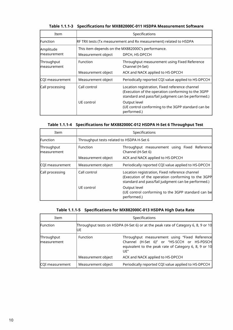
Table 1.1.1-3 Specifications for MX882000C-011 HSDPA Measurement Software
Item Specifications
Function RF TRX tests (Tx measurement and Rx measurement) related to HSDPA
Amplitude measurement
This item depends on the MX882000C’s performance.
Measurement object DPCH, HS-DPCCH
Throughput measurement
Function Throughput measurement using Fixed Reference Channel (H-Set)
Measurement object ACK and NACK applied to HS-DPCCH
CQI measurement Measurement object Periodically reported CQI value applied to HS-DPCCH
Call processing Call control Location registration, Fixed reference channel (Execution of the operation conforming to the 3GPP standard and pass/fail judgment can be performed.)
UE control Output level (UE control conforming to the 3GPP standard can be performed.)
Table 1.1.1-4 Specifications for MX882000C-012 HSDPA H-Set 6 Throughput Test
Item Specifications
Function Throughput tests related to HSDPA H-Set 6
Throughput measurement
Function Throughput measurement using Fixed Reference Channel (H-Set 6)
Measurement object ACK and NACK applied to HS-DPCCH
CQI measurement Measurement object Periodically reported CQI value applied to HS-DPCCH
Call processing Call control Location registration, Fixed reference channel (Execution of the operation conforming to the 3GPP standard and pass/fail judgment can be performed.)
UE control Output level (UE control conforming to the 3GPP standard can be performed.)
Table 1.1.1-5 Specifications for MX882000C-013 HSDPA High Data Rate
Item Specifications
Function Throughput tests on HSDPA (H-Set 6) or at the peak rate of Category 6, 8, 9 or 10 UE
Throughput measurement
Function Throughput measurement using “Fixed Reference Channel (H-Set 6)” or “HS-SCCH or HS-PDSCH equivalent to the peak rate of Category 6, 8, 9 or 10 UE”
Measurement object ACK and NACK applied to HS-DPCCH
CQI measurement Measurement object Periodically reported CQI value applied to HS-DPCCH
10
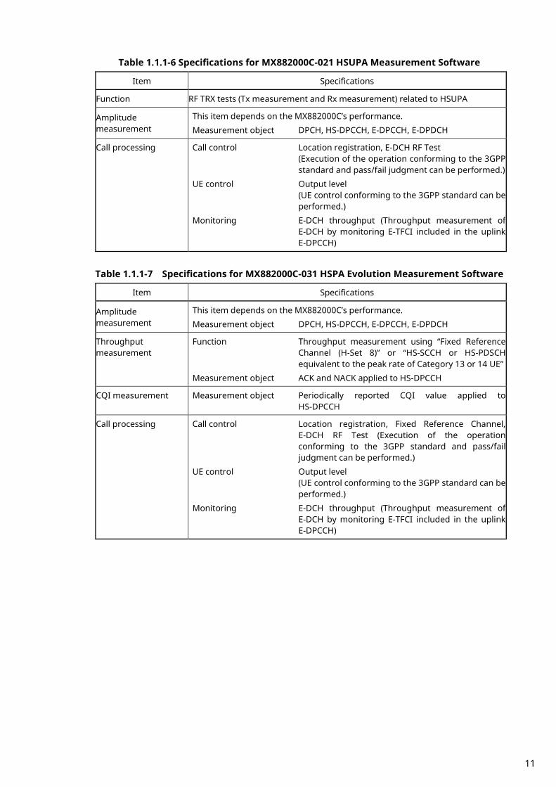
Table 1.1.1-6 Specifications for MX882000C-021 HSUPA Measurement Software
Item Specifications
Function RF TRX tests (Tx measurement and Rx measurement) related to HSUPA
Amplitude measurement
This item depends on the MX882000C’s performance.
Measurement object DPCH, HS-DPCCH, E-DPCCH, E-DPDCH
Call processing Call control Location registration, E-DCH RF Test (Execution of the operation conforming to the 3GPP standard and pass/fail judgment can be performed.)
UE control Output level (UE control conforming to the 3GPP standard can be performed.)
Monitoring E-DCH throughput (Throughput measurement of E-DCH by monitoring E-TFCI included in the uplink E-DPCCH)
Table 1.1.1-7 Specifications for MX882000C-031 HSPA Evolution Measurement Software
Item Specifications
Amplitude measurement
This item depends on the MX882000C’s performance.
Measurement object DPCH, HS-DPCCH, E-DPCCH, E-DPDCH
Throughput measurement
Function Throughput measurement using “Fixed Reference Channel (H-Set 8)” or “HS-SCCH or HS-PDSCH equivalent to the peak rate of Category 13 or 14 UE”
Measurement object ACK and NACK applied to HS-DPCCH
CQI measurement Measurement object Periodically reported CQI value applied to HS-DPCCH
Call processing Call control Location registration, Fixed Reference Channel, E-DCH RF Test (Execution of the operation conforming to the 3GPP standard and pass/fail judgment can be performed.)
UE control Output level (UE control conforming to the 3GPP standard can be performed.)
Monitoring E-DCH throughput (Throughput measurement of E-DCH by monitoring E-TFCI included in the uplink E-DPCCH)
11
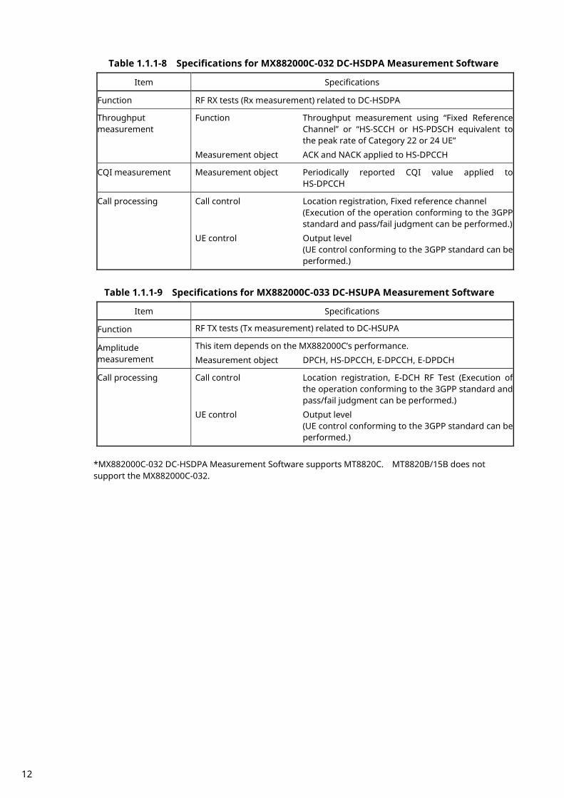
Table 1.1.1-8 Specifications for MX882000C-032 DC-HSDPA Measurement Software
Item Specifications
Function RF RX tests (Rx measurement) related to DC-HSDPA
Throughput measurement
Function Throughput measurement using “Fixed Reference Channel” or “HS-SCCH or HS-PDSCH equivalent to the peak rate of Category 22 or 24 UE”
Measurement object ACK and NACK applied to HS-DPCCH
CQI measurement Measurement object Periodically reported CQI value applied to HS-DPCCH
Call processing Call control Location registration, Fixed reference channel (Execution of the operation conforming to the 3GPP standard and pass/fail judgment can be performed.)
UE control Output level (UE control conforming to the 3GPP standard can be performed.)
Table 1.1.1-9 Specifications for MX882000C-033 DC-HSUPA Measurement Software
Item Specifications
Function RF TX tests (Tx measurement) related to DC-HSUPA
Amplitude measurement
This item depends on the MX882000C’s performance.
Measurement object DPCH, HS-DPCCH, E-DPCCH, E-DPDCH
Call processing Call control Location registration, E-DCH RF Test (Execution of the operation conforming to the 3GPP standard and pass/fail judgment can be performed.)
UE control Output level (UE control conforming to the 3GPP standard can be performed.)
*MX882000C-032 DC-HSDPA Measurement Software supports MT8820C. MT8820B/15B does not support the MX882000C-032.
12

1.1.2. MT8821C Specification Table 1.1.2-1Specifications for MX882100C W-CDMA Measurement Software
Item Specifications
Electrical characteristics
Typical values (typ.) are only for reference and are not guaranteed.
Frequency/ Modulation measurement
Frequency 350 to 2700 MHz For the frequencies below 500 MHz, only the
following range meets the specifications: 452.5 to 457.5 MHz (LTE Operating Band31) Input level –30 to +35 dBm (Main1/2) Carrier frequency accuracy
±(Set frequency ×Reference oscillator accuracy +10 Hz)
Modulation accuracy Residual vector error ≤2.5% (When one DPCCH signal and one DPDCH
signal are input) Amplitude measurement
Frequency 350 to 2700 MHz For the frequencies below 500 MHz, only the
following range meets the specifications: 452.5 to 457.5 MHz (LTE Operating Band31) Input level –65 to +35 dBm (Main1/2) Measurement accuracy ±0.5 dB (–30 to +35 dBm),
typ. ±0.3 dB (–30 to +35 dBm), ±0.7 dB (–55 to –30 dBm), ±0.9 dB (–65 to –55 dBm), after calibration 10 to 40°C
Linearity ±0.2 dB (–40 to 0 dB, ≥–55 dBm), ±0.4 dB (–40 to 0 dB, ≥–65 dBm),
Relative measurement error Range <2 dB
typ. ±0.10 dB (–40 to 0 dB, ≥–50 dBm) Measurement object DPCH, PRACH
13
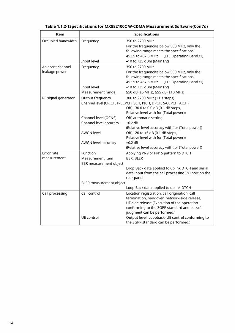
Table 1.1.2-1Specifications for MX882100C W-CDMA Measurement Software(Cont’d)
Item Specifications
Occupied bandwidth Frequency 350 to 2700 MHz For the frequencies below 500 MHz, only the
following range meets the specifications: 452.5 to 457.5 MHz (LTE Operating Band31) Input level –10 to +35 dBm (Main1/2)
Adjacent channel leakage power
Frequency 350 to 2700 MHz For the frequencies below 500 MHz, only the
following range meets the specifications: 452.5 to 457.5 MHz (LTE Operating Band31) Input level –10 to +35 dBm (Main1/2) Measurement range ≥50 dB (±5 MHz), ≥55 dB (±10 MHz)
RF signal generator Output frequency 300 to 2700 MHz (1 Hz steps) Channel level (CPICH, P-CCPCH, SCH, PICH, DPCH, S-CCPCH, AICH)
Off, –30.0 to 0.0 dB (0.1 dB steps, Relative level with Ior (Total power))
Channel level (OCNS) Off, automatic setting Channel level accuracy ±0.2 dB
(Relative level accuracy with Ior (Total power)) AWGN level Off, –20 to +5 dB (0.1 dB steps,
Relative level with Ior (Total power)) AWGN level accuracy ±0.2 dB
(Relative level accuracy with Ior (Total power)) Error rate measurement
Function Applying PN9 or PN15 pattern to DTCH Measurement item BER, BLER BER measurement object
Loop Back data applied to uplink DTCH and serial data input from the call processing I/O port on the rear panel
BLER measurement object Loop Back data applied to uplink DTCH
Call processing Call control Location registration, call origination, call termination, handover, network-side release, UE-side release (Execution of the operation conforming to the 3GPP standard and pass/fail judgment can be performed.)
UE control Output level, Loopback (UE control conforming to the 3GPP standard can be performed.)
14

Table 1.1.2-2 Specifications for MX882100C-001 W-CDMA Voice Codec
Item Specifications
Function End-to-end communications test between a handset connected to the MT8821C and UE. Encode the voice from Audio Input, Output the decoded voice to AF Output. Encode the tone signal and Output the tone signal to AF Output. Measure the voice signal from AF Input and decoded voice signal.
Voice codec AMR 12.2 kbps Codec level adjustment
Encoder input gain –3.00 to 3.00 dB, 0.01 dB steps Handset microphone volume 0, 1, 2, 3, 4, 5 Handset speaker volume 0, 1, 2, 3, 4, 5
AF output Frequency range 30 Hz to 10 kHz, Resolution 1 Hz Accuracy ±(Setting Frequency × Reference oscillator
accuracy +0.1 Hz) Level setting range 0 to 5 Vpeak (AF Output connector) Setting resolution 1 mV (≤5 Vpeak), 100 µV (≤500 mVpeak),
10 µV (≤50 mVpeak) Accuracy ±0.2 dB (≥10 mVpeak, ≥50 Hz),
±0.3 dB (≥10 mVpeak, <50 Hz) Waveform distortion Band at ≤30 kHz
≤–60 dB (≥500 mVpeak, ≤5 kHz), ≤–54 dB (≥70 mVpeak)
Output impedance ≤1 Ω Max. output current 100 mA
AF input Frequency range 50 Hz to 10 kHz Input voltage range 1 mVpeak to 5 Vpeak (AF Input connector) Max. allowable input voltage
30 Vrms Frequency measurement accuracy
±(Reference oscillator accuracy+0.5 Hz) Level measurement accuracy
±0.2 dB (≥10 mV peak, ≥50 Hz) ±0.4 dB (≥1 mV peak, ≥1 kHz)
SINAD measurement Frequency at 1 kHz ≥60 dB (≥1000 mV peak) ≥54 dB (>50 mV peak) ≥46 dB (≥10 mV peak)
Distortion rate measurement Frequency at 1 kHz ≤–60 dB (≥1000 mV peak) ≤–54 dB (>50 mV peak) ≤–46 dB (≥10 mV peak)
Input impedance 100 kΩ
15
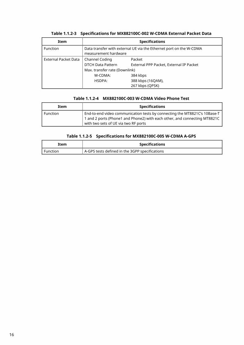
Table 1.1.2-3 Specifications for MX882100C-002 W-CDMA External Packet Data
Item Specifications
Function Data transfer with external UE via the Ethernet port on the W-CDMA measurement hardware
External Packet Data
Channel Coding Packet DTCH Data Pattern External PPP Packet, External IP Packet Max. transfer rate (Downlink)
W-CDMA: 384 kbps HSDPA: 388 kbps (16QAM),
267 kbps (QPSK)
Table 1.1.2-4 MX882100C-003 W-CDMA Video Phone Test
Item Specifications
Function End-to-end video communication tests by connecting the MT8821C’s 10Base-T 1 and 2 ports (Phone1 and Phone2) with each other, and connecting MT8821C with two sets of UE via two RF ports
Table 1.1.2-5 Specifications for MX882100C-005 W-CDMA A-GPS
Item Specifications
Function A-GPS tests defined in the 3GPP specifications
16

Table 1.1.2-6 Specifications for MX882100C-019 HSPA Measurement Software
Item Specifications
Function • RF TRX tests (Tx measurement and Rx measurement) related to HSPA and HSPA Evolution
• Throughput tests related to HSDPA on the Fixed Reference Channel (H-Set 6 or 8) or at the peak rate of Category 6, 8, 9, 10, 13 or 14 UE
Amplitude measurement
This item depends on the MX882100C’s performance. Measurement object DPCH, HS-DPCCH, E-DPCCH, E-DPDCH
Throughput measurement
Function • Throughput measurement using Fixed Reference Channel (H-Set)
• Throughput measurement using “FRC (H-Set 6 or 8)” and “HS-SCCH or HS-PDSCH equivalent to the peak rate of Category 6, 8, 9, 10, 13 or 14 UE”
Measurement object ACK and NACK applied to HS-DPCCH Call processing Call control Location registration, Fixed Reference Channel,
E-DCH RF Test (Execution of the operation conforming to the 3GPP standard and pass/fail judgment can be performed.)
UE control Output level (UE control conforming to the 3GPP standard can be performed.)
Monitoring E-DCH throughput (Throughput measurement of E-DCH by monitoring E-TFCI included in the uplink E-DPCCH)
Table 1.1.2-7 Specifications for MX882100C-032 DC-HSDPA Measurement Software
Item Specifications
Function RF RX tests (Rx measurement) related to DC-HSDPA Throughput measurement
Function Throughput measurement that uses HS-SCCH or HS-PDSCH equivalent to the peak rate of Category 22 or 24 UE
Measurement object ACK and NACK applied to HS-DPCCH CQI measurement Measurement object Periodically reported CQI value applied to
HS-DPCCH Call processing Call control Location registration, Fixed reference channel
(Execution of the operation conforming to the 3GPP standard and pass/fail judgment can be performed.)
UE control Output level (UE control conforming to the 3GPP standard can be performed.)
17

Table 1.1.2-8 Specifications for MX882100C-033 DC-HSUPA Measurement Software
Item Specifications
Function RF TX tests (Tx measurement) related to DC-HSUPA
Amplitude measurement
This item depends on the MX882100C’s performance. Measurement object DPCH, HS-DPCCH, E-DPCCH, E-DPDCH
Call processing Call control Location registration, E-DCH RF Test (Execution of the operation conforming to the 3GPP standard and pass/fail judgment can be performed.)
UE control Output level (UE control conforming to the 3GPP standard can be performed.)
18

1.2. 3GPP Measurement Specification Table 1.2.1. MX882000C/MX882100C - MT8820B/20C/21C W-CDMA Measurement Software
Item (TS 34.121 V9.4.0) Comment
5 Transmitter Characteristics
5.2 Maximum Output Power √√
5.2A Maximum Output Power with HS-DPCCH (Release 5 only) MX882000C-011
MX882100C-019
√√
5.2AA Maximum Output Power with HS-DPCCH (Release 6 and later) MX882000C-011
MX882100C-019
√√
5.2B Maximum Output Power with HS-DPCCH and E-DCH MX882000C-021
MX882100C-019
√√
5.2BA UE Maximum Output Power for DC-HSUPA(QPSK) MX882000C-033
MX882100C-033
√√
5.2BB UE Maximum Output Power for DC-HSUPA(16QAM) MX882000C-033
MX882100C-033
√√
5.2C UE relative code domain power accuracy MX882000C-011
MX882100C-019
√√
5.2D UE Relative Code Domain Power Accuracy for HS-DPCCH and
EDCH
MX882000C-021
MX882100C-019
√√
5.2DA UE Relative Code Domain Power Accuracy for DC-HSUPA with QPSK
MX882000C-033
MX882100C-033
√√
5.2E UE Relative Code Domain Power Accuracy for HS-DPCCH and
E-DCH with 16QAM
MX882000C-031
MX882100C-019
√√
5.2EA UE Relative Code Domain Power Accuracy for DC-HSUPA with 16QAM
MX882000C-033
MX882100C-019
√√
5.3 Frequency Error √√
5.3A Frequency Error for DC-HSUPA MX882000C-033
MX882100C-033
√√
5.4 Output Power Dynamics in Uplink
5.4.1 Open Loop Power Control in Uplink √√
5.4.1A Open Loop Power Control in Uplink for DC-HSUPA MX882000C-033
MX882100C-033
√√
5.4.2 Inner Loop Power Control in Uplink √√
5.4.2A Inner Loop Power Control in Uplink for DC-HSUPA MX882000C-033
MX882100C-033
√√
5.4.3 Minimum Output Power √√
5.4.4 Out-of-synchronisation handling of output power √√
5.4.4A Out-of-synchronisation handling of output power for a UE
which supports type1 for DCH
√√
5.5 Transmit ON/OFF Power √√
5.6 Change of TFC √√
5.7 Power setting in uplink compressed mode √√
5.7A HS-DPCCH (Rel-6) MX882000C-011
MX882100C-019
√√
5.7A HS-DPCCH Power Control (Rel-7 and later) MX882000C-011 √√
19

MX882100C-019
5.8 Occupied Bandwidth (OBW) √√
5.8A Occupied Bandwidth (OBW) for DC-HSUPA MX882000C-033
MX882100C-033
√√
5.9 Spectrum emission mask √√
5.9A Spectrum Emission Mask with HS-DPCCH MX882000C-011
MX882100C-019
√√
5.9B Spectrum Emission Mask with E-DCH MX882000C-021
MX882100C-019
√√
5.9C Additional Spectrum Emission Mask for DC-HSUPA(QPSK) MX882000C-033
MX882100C-033
√√
5.9D Additional Spectrum Emission Mask for DC-HSUPA(16QAM) MX882000C-033
MX882100C-033
√√
5.10 Adjacent Channel Leakage Power Ratio (ACLR) √√
5.10A Adjacent Channel Leakage Power Ratio (ACLR) with HS-DPCCH MX882000C-011
MX882100C-019
√√
5.10B Adjacent Channel Leakage Power Ratio (ACLR) with E-DCH MX882000C-021
MX882100C-019
√√
5.10C Adjacent Channel Leakage Power Ratio (ACLR) with E-DCH for
DC-HSUPA(QPSK)
MX882000C-033 MX882100C-033
√√
5.10D Adjacent Channel Leakage Power Ratio (ACLR) with E-DCH for
DC-HSUPA(16QAM)
MX882000C-033 MX882100C-033
√√
5.11 Spurious Emissions Requires SPA √
5.12 Transmit Intermodulation Requires SG and SPA √
5.13 Transmit Modulation
5.13.1 Error Vector Magnitude (EVM) √√
5.13.1A Error Vector Magnitude (EVM) with HS-DPCCH (Rel-6) MX882000C-011
MX882100C-019
√√
5.13.1A Error Vector Magnitude (EVM) with HS-DPCCH (Rel-7 and later) MX882000C-011
MX882100C-019
√√
5.13.1AA Error Vector Magnitude (EVM) and phase discontinuity with
HS-DPCCH
MX882000C-011
MX882100C-019
√√
5.13.1AA
A
EVM and IQ origin offset for HS-DPCCH and E-DCH with 16
QAM
MX882000C-031
MX882100C-019
√√
5.13.2 Peak code domain error Single Code Only √√
5.13.2A Relative Code Domain Error with HS-DPCCH MX882000C-011
MX882100C-019
√√
5.13.2B Relative Code Domain Error with HS-DPCCH and E-DCH MX882000C-021
MX882100C-019
√√
5.13.2BA Relative Code Domain Error with HS-DPCCH and E-DCH for
DC-HSUPA
MX882000C-033
MX882100C-033
√√
5.13.2C Relative Code Domain Error for HS-DPCCH and E-DCH with
16QAM
MX882000C-031
MX882100C-019
√√
5.13.2CA Relative Code Domain Error for HS-DPCCH and E-DCH 16QAM for DC-HSUPA
MX882000C-033
MX882100C-033
√√
5.13.3 UE phase discontinuity √√
5.13.4 PRACH preamble quality √√
20
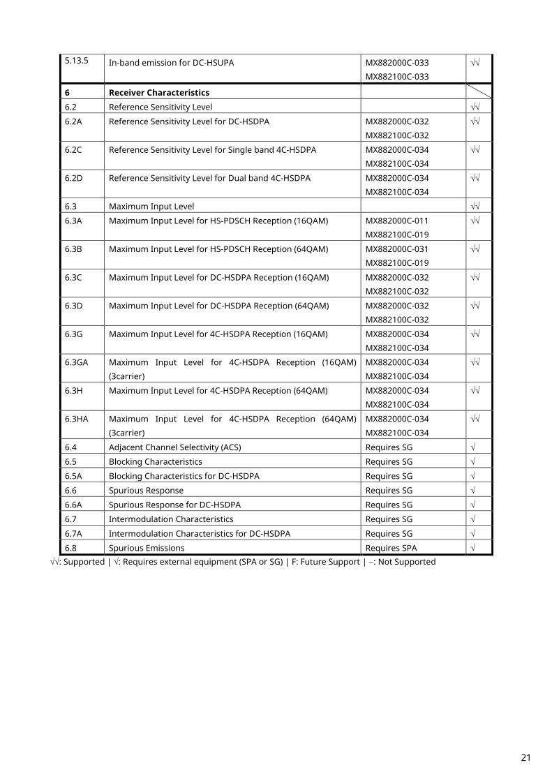
5.13.5 In-band emission for DC-HSUPA MX882000C-033
MX882100C-033
√√
6 Receiver Characteristics
6.2 Reference Sensitivity Level √√
6.2A Reference Sensitivity Level for DC-HSDPA MX882000C-032
MX882100C-032
√√
6.2C Reference Sensitivity Level for Single band 4C-HSDPA MX882000C-034
MX882100C-034
√√
6.2D Reference Sensitivity Level for Dual band 4C-HSDPA MX882000C-034
MX882100C-034
√√
6.3 Maximum Input Level √√
6.3A Maximum Input Level for HS-PDSCH Reception (16QAM) MX882000C-011
MX882100C-019
√√
6.3B Maximum Input Level for HS-PDSCH Reception (64QAM) MX882000C-031
MX882100C-019
√√
6.3C Maximum Input Level for DC-HSDPA Reception (16QAM) MX882000C-032
MX882100C-032
√√
6.3D Maximum Input Level for DC-HSDPA Reception (64QAM) MX882000C-032
MX882100C-032
√√
6.3G Maximum Input Level for 4C-HSDPA Reception (16QAM) MX882000C-034
MX882100C-034
√√
6.3GA Maximum Input Level for 4C-HSDPA Reception (16QAM)
(3carrier)
MX882000C-034
MX882100C-034
√√
6.3H Maximum Input Level for 4C-HSDPA Reception (64QAM) MX882000C-034
MX882100C-034
√√
6.3HA Maximum Input Level for 4C-HSDPA Reception (64QAM)
(3carrier)
MX882000C-034
MX882100C-034
√√
6.4 Adjacent Channel Selectivity (ACS) Requires SG √
6.5 Blocking Characteristics Requires SG √
6.5A Blocking Characteristics for DC-HSDPA Requires SG √
6.6 Spurious Response Requires SG √
6.6A Spurious Response for DC-HSDPA Requires SG √
6.7 Intermodulation Characteristics Requires SG √
6.7A Intermodulation Characteristics for DC-HSDPA Requires SG √
6.8 Spurious Emissions Requires SPA √ √√: Supported | √: Requires external equipment (SPA or SG) | F: Future Support | −: Not Supported
21
Item Comment
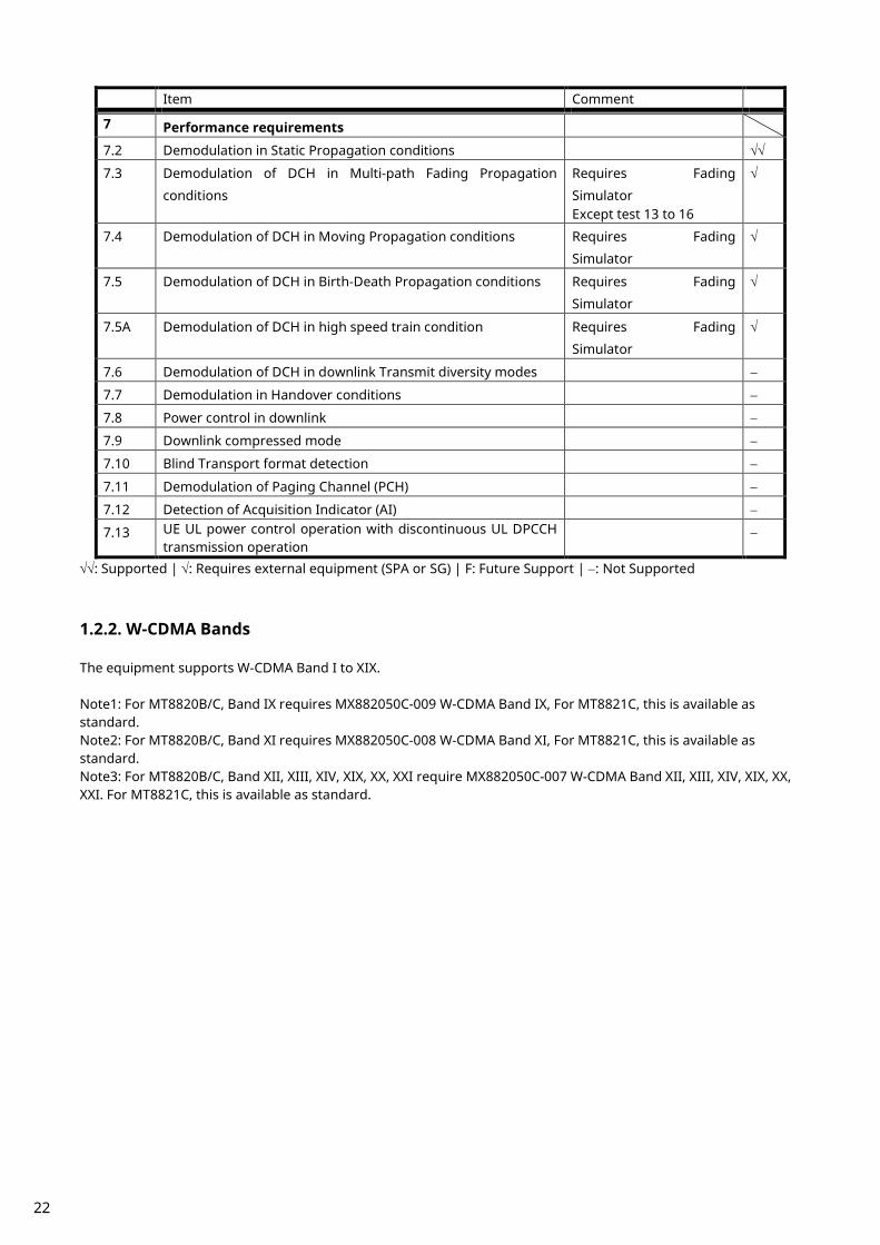
7 Performance requirements
7.2 Demodulation in Static Propagation conditions √√
7.3 Demodulation of DCH in Multi-path Fading Propagation
conditions
Requires Fading
Simulator Except test 13 to 16
√
7.4 Demodulation of DCH in Moving Propagation conditions Requires Fading
Simulator
√
7.5 Demodulation of DCH in Birth-Death Propagation conditions Requires Fading
Simulator
√
7.5A Demodulation of DCH in high speed train condition Requires Fading
Simulator
√
7.6 Demodulation of DCH in downlink Transmit diversity modes −
7.7 Demodulation in Handover conditions −
7.8 Power control in downlink −
7.9 Downlink compressed mode −
7.10 Blind Transport format detection −
7.11 Demodulation of Paging Channel (PCH) −
7.12 Detection of Acquisition Indicator (AI) −
7.13 UE UL power control operation with discontinuous UL DPCCH transmission operation
−
√√: Supported | √: Requires external equipment (SPA or SG) | F: Future Support | −: Not Supported
1.2.2. W-CDMA Bands The equipment supports W-CDMA Band I to XIX. Note1: For MT8820B/C, Band IX requires MX882050C-009 W-CDMA Band IX, For MT8821C, this is available as standard. Note2: For MT8820B/C, Band XI requires MX882050C-008 W-CDMA Band XI, For MT8821C, this is available as standard. Note3: For MT8820B/C, Band XII, XIII, XIV, XIX, XX, XXI require MX882050C-007 W-CDMA Band XII, XIII, XIV, XIX, XX, XXI. For MT8821C, this is available as standard.
22

1.3. TRX Measurement (Fundamental Measurement) The control software is presupposed to have been created using GPIB. See the operation manual for details of GPIB commands and manual operations. GPIB commands are in bold red.
1.3.1. Connection with Test Loop Mode Measurement is performed with Test Loop Mode1. The connection procedures are shown below. By turning off ATT Flag, the UE can stop location registration (only inside registered network). If location registration is not needed, turn off the ATT Flag (ATTFLAG OFF) before turning on UE power. For optimum measurement, connection should be executed after turning off the Measurement Report (MEASREP OFF).
1. Execute PRESET_3GPP to preset parameter for 3GPP. 2. Execute INTEGRITY ON to set [Integrity Protection] to [On]. 3. Execute DRXCYCLNG 64 to set [DRX Cycle Length] to [64] Frame (= 640 ms). 4. Turn on the UE power. 5. Execute CALLSTAT? and wait until the response becomes 2 (= Idle (Regist)). 6. Execute CALLSA to connect with Test Loop Mode1. 7. Execute CALLSTAT? and wait until the response becomes 7 (= Test Loop Mode 1).
1.3.2. Disconnection with Test Loop Mode
1. Execute CALLSO to disconnect with Test Loop Mode1. 2. Execute CALLSTAT? and wait until the response becomes 2 (= Idle(Regist)).
1.3.3. Channel Switching using Handover Usually, measurement is performed at three frequency points (L, M, H). In this case, the Channel can be switched quickly without reconnection by switching it at handover with a higher output level. When a GPIB command is sent during handover, it waits until handover ends.
1. Execute TRX measurement at M channel. 2. Execute CHAN 9613 to handover to L channel. 3. Execute TRX measurement. 4. Execute CHAN 9887 to handover to H channel. 5. Execute TRX measurement.
1.3.4. Selecting Test Items Set unnecessary items, such as BER and BLER measurements (BER_MEAS OFF, BLER_MEAS OFF), to off to reduce measurement time. Execute ALLMEASITEMS_OFF to set all measurements to off.
23

1.3.5. 5.2 Maximum Output Power
1. Connect with Test Loop Mode1. 2. Execute ILVL 35.0 to set Input Level to [+35.0] dBm. 3. Execute OLVL -106 to set [Output Level] to [–106] dBm. 4. Execute TPCPAT ALL1 to set [Power Control Bit Pattern] to [ALL1]. 5. Execute PWR_MEAS ON to set [Power Measurement] to [On]. 6. Execute PWR_AVG 20 to set [Average Count] of power measurement to [20] times. 7. Execute SWP to perform power measurement. 8. Execute AVG_POWER? to read the power measurement result. 9. Confirm the measurement result is 24 dBm (Tolerance +1.7/-3.7 dB).
TX Power means Mean power (5 MHz band), and Filtered Power means RRC filtered mean power.
1.3.6. 5.3 Frequency Error Average measurement result is the average value of signed measurement results. Max and Min results must be used.
1. Connect with Test Loop Mode1. 2. Execute ILVL 35.0 to set [Input Level] to [+35.0] dBm. 3. Execute OLVL -106 to set [Output Level] to [–106] dBm. 4. Execute TPCPAT ALL1 to set [Power Control Bit Pattern] to [ALL1]. 5. Execute FREQ_MEAS ON to set [Frequency Error] measurement to [On]. 6. Execute FREQ_AVG 20 to set [Average Count] of Frequency Error measurement to [20] times. 7. Execute SWP to perform Frequency Error measurement. 8. Execute MAX_CARRFERR? PPM to read the Frequency Error measurement result. 9. Execute MIN_CARRFERR? PPM to read the Frequency Error measurement result.
10. Confirm the measurement result is lower than (0.1 ppm + 10 Hz). Max and Min results must be used for signed measurements such as Frequency Error.
24

1.3.7. 5.7 Power setting in uplink compressed mode 1. Connect with Test Loop Mode1. (Refer to 1.3.1.) 2. Execute SCRSEL TDMEAS to display the Time Domain Measurement screen. 3. Execute MEASOBJ COMPRESS to set [Measurement Object] to [Compressed Mode]. 4. Execute TPCSTEP 2 to set [TPC Step Size] to [2 dB]. 5. Execute ILVL -36.0 to set [Input Level] to [-36.0] dBm. 6. Wait until the UE power is -36.0 dBm. 7. Execute TPCPAT ALT to set [Power Control Bit Pattern] to [Alternate]. [Pattern A(Up)] 8. Execute ILP_TPC PAT_A_UP to set [TPC Method] to [Pattern A(Up)]. 9. Execute ILVL -16.0 to set [Input Level] to [-16.0] dBm. 10. Execute SWP to perform measurement. 11. Execute COMPPASS? to read the measurement result. 12. Confirm the measurement result is PASS.
[Pattern A(Down)] 13. Execute ILP_TPC PAT_A_DOWN to set [TPC Method] to [Pattern A(Down)]. 14. Execute TPCPAT ILPC to set [Power Control Bit Pattern] to [Inner Loop Power Control]. 15. Execute ILVL 2.0 to set [Input Level] to [2.0] dBm. 16. Wait about 30ms until the UE power becomes [2.0] dBm. 17. Execute SWP to perform measurement. 18. Execute COMPPASS? to read the measurement result. 19. Confirm the measurement result is PASS.
25

[Pattern B] 20. Execute ILP_TPC PAT_B to set [TPC Method] to [Pattern B]. 21. Execute TPCPAT ILPC to set [Power Control Bit Pattern] to [Inner Loop Power Control]. 22. Execute ILVL -10.0 to set [Input Level] to [-10.0] dBm. 23. Wait about 30ms until the UE power becomes [-10.0] dBm. 24. Execute TPCSTEP 1 to set [TPC Step Size] to [1 dB]. 25. Execute SWP to perform measurement. 26. Execute COMPPASS? to read the measurement result. 27. Confirm the measurement result is PASS.
26

1.3.8. 5.8 Occupied Bandwidth
1. Connect with Test Loop Mode1. 2. Execute ILVL 35.0 to set [Input Level] to [+35.0] dBm. 3. Execute OLVL -106 to set [Output Level] to [–106] dBm. 4. Execute TPCPAT ALL1 to set [Power Control Bit Pattern] to [ALL1]. 5. Execute OBW_MEAS ON to set [Occupied Bandwidth] measurement to [On]. 6. Execute OBW_AVG 20 to set [Average Count] of Occupied Bandwidth measurement to [20] times. 7. Execute SWP to perform Occupied Bandwidth measurement. 8. Execute OBW? to read the Occupied Bandwidth measurement result. 9. Confirm the measurement result lower than 5 MHz.
1.3.9. 5.9 Spectrum Emission Mask
1. Connect with Test Loop Mode1. 2. Execute ILVL 35.0 to set [Input Level] to [+35.0] dBm. 3. Execute OLVL -106 to set [Output Level] to [–106] dBm. 4. Execute TPCPAT ALL1 to set [Power Control Bit Pattern] to [ALL1]. 5. Execute SMASK_MEAS ON to set [Spectrum Emission Mask] measurement to [On]. 6. Execute SMASK_AVG 20 to set [Average Count] of Spectrum Emission Mask measurement to [20] times. 7. Execute SWP to perform Spectrum Emission Mask measurement. 8. Execute SMASKPASS? to read the Spectrum Emission Mask measurement result. 9. Confirm the measurement result is PASS.
27

1.3.10. 5.10 Adjacent Channel Leakage Power
1. Connect with Test Loop Mode1. 2. Execute ILVL 35.0 to set [Input Level] to [+35.0] dBm. 3. Execute OLVL -106 to set [Output Level] to [–106] dBm. 4. Execute TPCPAT ALL1 to set [Power Control Bit Pattern] to [ALL1]. 5. Execute ADJ_MEAS ON to set [Adjacent Channel Power] measurement to [On]. 6. Execute ADJ_AVG 20 to set [Average Count] of Adjacent Channel Power measurement to [20] times. 7. Execute SWP to perform Adjacent Channel Power measurement. 8. Execute AVG_MODPWR? LOW10 to read the Adjacent Channel Power measurement result. 9. Confirm the measurement result is lower than -42.2 dB.
10. Execute AVG_MODPWR? LOW5 to read the Adjacent Channel Power measurement result. 11. Confirm the measurement result is lower than -32.2 dB. 12. Execute AVG_MODPWR? UP5 to read the Adjacent Channel Power measurement result. 13. Confirm the measurement result is lower than-32.2 dB. 14. Execute AVG_MODPWR? UP10 to read the Adjacent Channel Power measurement result. 15. Confirm the measurement result is lower than –42.2 dB.
28

1.3.11. 5.13.1 Error Vector Magnitude (EVM)
1. Connect with Test Loop Mode1. 2. Execute ILVL 35.0 to set [Input Level] to [+35.0] dBm. 3. Execute OLVL -106 to set [Output Level] to [–106] dBm. 4. Execute TPCPAT ALL1 to set [Power Control Bit Pattern] to [ALL1]. 5. Execute INC_ORGNOFS ON to set [EVM include Origin Offset] to [On]. 6. Execute MOD_MEAS ON to set [Modulation Analysis] measurement to [On]. 7. Execute MOD_AVG 20 to set [Average Count] of Modulation Analysis measurement to [20] times. 8. Execute SWP to perform modulation analysis measurement. 9. Execute AVG_EVM? to read the EVM (Error Vector Magnitude) measurement result.
10. Confirm the measurement result is lower than 17.5%. 11. Execute TOCALGO 2 to set [Power Control Algorithm] to [Algorithm 2]. 12. Execute TPCPAT ILPC to set [Power Control Bit Pattern] to [Inner Loop Power Control]. 13. Execute ILVL -18.0 to set [Input Level] to [–18.0] dBm. 14. Wait about 200mm seconds until the UE power becomes [–18.0] dBm. 15. Execute TPCPAT ALT to set [Power Control Bit Pattern] to [Alternate]. 16. Repeat procedures 8, 9, and 10.
1.3.12. 6.2 Reference Sensitivity Level
1. Connect with Test Loop Mode1. 2. Execute ILVL 35.0 to set [Input Level] to [+35.0] dBm. 3. Execute OLVL -106 to set [Output Level] to [–106] dBm. (in case of Band I) 4. Execute TPCPAT ALL1 to set [Power Control Bit Pattern] to [ALL1]. 5. Execute BER_MEAS ON to set [Bit Error Rate] measurement to [On]. 6. Execute BER_SAMPLE 10000 to set [Number of Sample] at BER measurement to [10000] bits. 7. Execute SWP to perform BER measurement. 8. Execute BER? to read the BER measurement result. 9. Confirm the measurement result is lower than 0.001 (0.1%).
29

1.3.13. Measurement Time Reduction using Batch Process The above TRX test items can be measured under the same measurement condition, so measurement time can be reduced by performing all measurements simultaneously.
1. Connect with Test Loop Mode1. 2. Execute ILVL 35.0 to set [Input Level] to [+35.0] dBm. 3. Execute OLVL -106 to set [Output Level] to [–106] dBm. 4. Execute TPCPAT ALL1 to set [Power Control Bit Pattern] to [ALL1]. 5. Execute INC_ORGNOFS ON to set [EVM include Origin Offset] to [On]. 6. Execute ALLMEASITEMS ON,20,ON,20,ON,20,ON,20,ON,20,ON,20,OFF,1,ON,OFF, to set all measurements
to [On] other than [Code Domain Power] and [BLER Measurement], and to set [Average Count] to [20] times. 7. Execute BER_SAMPLE 10000 to set [Number of Sample] at BER measurement samples to [10000] bits. 8. Execute SWP to perform the measurement. 9. Execute AVG_POWER?, etc., to read the measurement result.
*There are items that cannot be measured with the same parameter.
1.3.14. 5.4.3 Minimum Output Power The procedure, how to measure Minimum Output Power on Fundamental Measurement screen, is shown below (It can be also measured simultaneously with Inner Loop Power Control in the Uplink STEP E, G).
1. Execute SCRSEL FMEAS to display the Fundamental Measurement screen. 2. Execute ILVL -30.0 to set [Input Level] to [–30.0] dBm. 3. Execute OLVL -93.0 to set [Output Level] to [–93.0] dBm. 4. Execute TPCPAT ALL0 to set [Power Control Bit Pattern] to [ALL0]. 5. Execute PWR_MEAS ON to set [Power Measurement] to [On]. 6. Execute PWR_AVG 20 to set [Average Count] of power measurement to [20] times. 7. Execute SWP to perform the measurement. 8. Execute AVG_POWER? to read the power measurement result. 9. Confirm the measurement result is lower than –49 dBm.
30
1.4. Open Loop Power Control Measurement The following is measured using RACH with Time Mask measurement on the Time Domain Measurement screen. On the Time Domain Measurement screen, RRC Filter Off (TDM_RRC OFF) corresponds to Mean power (5 MHz band), and RRC Filter On (TDM_RRC ON) corresponds to RRC filtered mean power.
1. Execute SCRSEL TDMEAS to display the Time Domain Measurement screen. 2. Execute MEASOBJ RACHTMSK to set [Measurement Object] to [RACH with Time Mask]. 3. Execute TIMSPAN 4.0MS to set [Time Span] of Time Domain measurement to [4.0] ms. 4. Execute TRGDELAY -1.0MS to set [Trigger Delay] of Time Domain measurement to [–1.0] ms. 5. Execute MAXULPWR 24 to set [Maximum Allowed UL TX Power] to [24.0] dBm. 6. Execute RABCONNECT OFF_FAST to set [RAB connection] to [Off - Fast].
Maximum Allowed TX Power is a standard parameter of Cell Selection and Reselection. Power Class must be set lower than Maximum Allowed TX Power, so the UE can perform Cell Selection and Reselection with Sensitivity Level. For example, when UE Power Class is 3, MAXULPWR is 24.0. By turning off RAB connection, the call status can be returned to Idle without connecting RAB at Test Loop Mode connection.
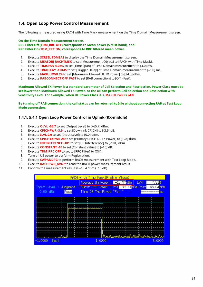
1.4.1. 5.4.1 Open Loop Power Control in Uplink (RX-middle)
1. Execute OLVL -65.7 to set [Output Level] to [–65.7] dBm. 2. Execute CPICHPWR -3.9 to set [Downlink CPICH] to [-3.9] dB. 3. Execute ILVL 0.0 to set [Input Level] to [0.0] dBm. 4. Execute CPICHTXPWR 28 to set [Primary CPICH DL TX Power] to [+28] dBm. 5. Execute INTERFERENCE -101 to set [UL Interference] to [–101] dBm. 6. Execute CONSTANT -10 to set [Constant Value] to [–10] dB. 7. Execute TDM_RRC OFF to set to [RRC Filter] to [Off]. 8. Turn on UE power to perform Registration. 9. Execute SWPANDPG to perform RACH measurement with Test Loop Mode.
10. Execute RACHPWR_AVG? to read the RACH power measurement result. 11. Confirm the measurement result is –13.4 dBm (±10 dB).
31

1.4.2. 5.4.1 Open Loop Power Control in Uplink (RX Upper dynamic end)
1. Execute OLVL -25.0 to set [Output Level] to [ovel]t dBm. 2. Execute CPICHPWR -3.9 to set [Downlink CPICH] to [-3.9] dB. 3. Execute ILVL -25.0 to set [Input Level] to [ovel]e dBm. 4. Execute CPICHTXPWR 19 to set [Primary CPICH DL TX Power] to [+19] dBm. 5. Execute INTERFERENCE -75 to set [UL Interference] to [–75] dBm. 6. Execute CONSTANT -10 to set [Constant Value] to [–10] dB. 7. Execute TDM_RRC OFF to set [RRC Filter] to [Off]. 8. Turn on the UE to perform Registration. 9. Execute SWPANDPG to perform RACH measurement with Test Loop Mode.
10. Execute RACHPWR_AVG? to read the RACH power measurement result. 11. Confirm the measurement result is –37.1 dBm (±10 dB).
32

1.4.3. 5.4.1 Open Loop Power Control in Uplink (RX-Sensitivity level)
1. Execute OLVL -65.7 to set [Output Level] to [–65.7] dBm. 2. Execute CPICHPWR -3.9 to set [Downlink CPICH] to [-3.9] dB. 3. Execute ILVL 25.0 to set [Input Level] to [+25.0] dBm. 4. Execute CPICHTXPWR 19 to set [Primary CPICH DL TX Power] to [+19] dBm. 5. Execute INTERFERENCE -110 to set [UL Interference] to [–110] dBm. 6. Execute CONSTANT -10 to set [Constant Value] to [–10] dB. 7. Execute TDM_RRC OFF to set [RRC Filter] to [Off]. 8. Turn on the UE and perform Registration. 9. Execute OLVL -106.7 to set [Output Level] to [–106.7] dBm.
10. Execute SWPANDPG to perform RACH measurement with Test Loop Mode. 11. Execute RACHPWR_AVG? to read the RACH power measurement result. 12. Confirm the measurement result is +8.9 dBm (±10 dB).
33
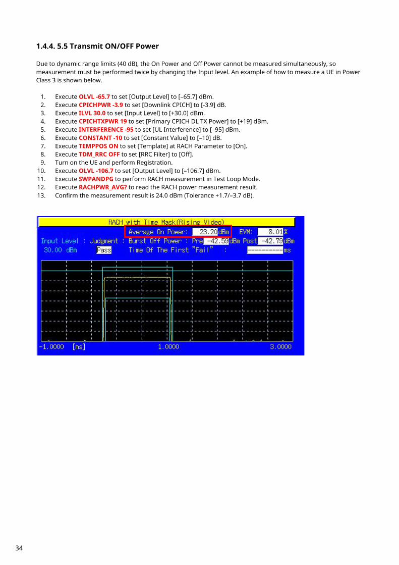
1.4.4. 5.5 Transmit ON/OFF Power Due to dynamic range limits (40 dB), the On Power and Off Power cannot be measured simultaneously, so measurement must be performed twice by changing the Input level. An example of how to measure a UE in Power Class 3 is shown below.
1. Execute OLVL -65.7 to set [Output Level] to [–65.7] dBm. 2. Execute CPICHPWR -3.9 to set [Downlink CPICH] to [-3.9] dB. 3. Execute ILVL 30.0 to set [Input Level] to [+30.0] dBm. 4. Execute CPICHTXPWR 19 to set [Primary CPICH DL TX Power] to [+19] dBm. 5. Execute INTERFERENCE -95 to set [UL Interference] to [–95] dBm. 6. Execute CONSTANT -10 to set [Constant Value] to [–10] dB. 7. Execute TEMPPOS ON to set [Template] at RACH Parameter to [On]. 8. Execute TDM_RRC OFF to set [RRC Filter] to [Off]. 9. Turn on the UE and perform Registration.
10. Execute OLVL -106.7 to set [Output Level] to [–106.7] dBm. 11. Execute SWPANDPG to perform RACH measurement in Test Loop Mode. 12. Execute RACHPWR_AVG? to read the RACH power measurement result. 13. Confirm the measurement result is 24.0 dBm (Tolerance +1.7/–3.7 dB).
34
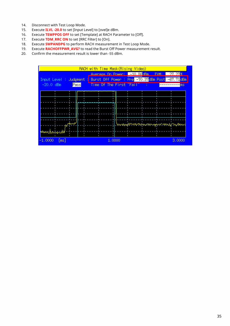
14. Disconnect with Test Loop Mode. 15. Execute ILVL -20.0 to set [Input Level] to [ovel]e dBm. 16. Execute TEMPPOS OFF to set [Template] at RACH Parameter to [Off]. 17. Execute TDM_RRC ON to set [RRC Filter] to [On]. 18. Execute SWPANDPG to perform RACH measurement in Test Loop Mode. 19. Execute RACHOFFPWR_AVG? to read the Burst Off Power measurement result. 20. Confirm the measurement result is lower than -55 dBm.
35

1.4.5. 5.13.4 PRACH Preamble Quality Although RACH Sub Channel and PRACH Signature cannot be specified, the EVM and Frequency Error of RACH can be measured. An example of how to measure a UE in Power Class3 is shown below.
1. Execute OLVL -98.1 to set [Output Level] to [–ovel] dBm. 2. Execute CPICHPWR -3.9 to set [Downlink CPICH] to [-3.9] dB. 3. Execute ILVL 30.0 to set [Input Level] to [+30.0] dBm. 4. Execute CPICHTXPWR 24 to set [Primary CPICH DL TX Power] to [+24] dBm. 5. Execute INTERFERENCE -92 to set [UL Interference] to [–92] dBm. 6. Execute CONSTANT -10 to set [Constant Value] to [–10] dB. 7. Turn on the UE and perform Registration. 8. Execute SWPANDPG to perform RACH measurement in Test Loop Mode. 9. Execute RACHEVM? to read the RACH EVM measurement result.
10. Confirm the measurement result is lower than 17.5%. 11. Execute RACHFERR? PPM to read the RACH Frequency Error measurement result. 12. Confirm the measurement result is lower than (0.1 ppm + 10 Hz).
1.4.6. Continuous Measurement of Open Loop Power Control Open Loop Power Control measurement is performed by changing Primary CPICH DL TX Power, UL Interference and Constant Value. However, these parameters are for broadcast information, so some time is required to reflect the parameter changes at the UE side. To perform continuous Open Loop Power Control measurement, the parameters must be reflected at the UE using one of following methods.
1) Wait about 5 s after changing parameters (when changing parameters, the equipment sends BCCH modification info to the UE as PAGING TYPE1 message. It takes about 5 s until the UE reflects the changes).
2) Turn on the UE power again after changing the parameters and wait until the UE starts Registration. 3) In addition to changing the above parameters, change the LAC parameter and wait until the UE starts Registration.
The UE can be notified quickly about the change of broadcast information by executing DRXCYCLNG 64 to set [CN DRX Cycle Length] to [64] Frame, which is the minimum value.
36

1.5. Inner Loop Power Control Measurement
1.5.1. 5.4.2 Inner Loop Power Control in the Uplink
1. Execute SCRSEL TDMEAS to display the Time Domain Measurement screen. 2. Execute MEASOBJ ILPC_AUTO to set [Measurement Object] to [Inner Loop Power Control (Auto)]. 3. Execute OLVL -93 to set [Output Level] to [–93] dBm. 4. Connect using Test Loop Mode1. 5. Execute ILPC_MEAS AUTO_ALL to set [ILPC Measurement Method] to [Auto (Step All)]. 6. Execute SWP to perform measurement. 7. Execute ILPC_PASS? ALL and check the measurement result is PASS.
37

1.5.2. 5.13.3 UE Phase Discontinuity UE phase discontinuity uses Phase Discontinuity measurement on the Time Domain Measurement screen. Due to dynamic range limits (40 dB), measurement cannot be performed once; it must be executed four times with different Input Levels.
1. Execute SCRSEL TDMEAS to display the Time Domain Measurement screen. 2. Execute MEASOBJ PHASEDISC to set [Measurement Object] to [Phase Discontinuity]. 3. Execute SLOTLIST ON to display slot list. 4. Execute REGSLOTLIST 0-359 to register Slot0~Slot359 for the slot list. 5. Execute TIMESPAN 240.0MS to set [Time Span] of Time Domain measurement to [240.0] ms. 6. Execute OLVL –93 to set [Output Level] to [–93] dBm. 7. Execute TPCALGO 1 to set [Power Control Algorithm] to [Algorithm 1]. 8. Execute TPCSTEP 1 to set [TPC Step Size] to [1 dB]. 9. Execute TDM_RRC OFF to set [RRC Filter] to [Off].
10. Connect with Test Loop Mode1. 11. Execute ILVL 25.0 to set [Input Level] to [+25.0] dBm. 12. Execute TPCPAT ALL1 to set [Power Control Bit Pattern] to [ALL1].
38
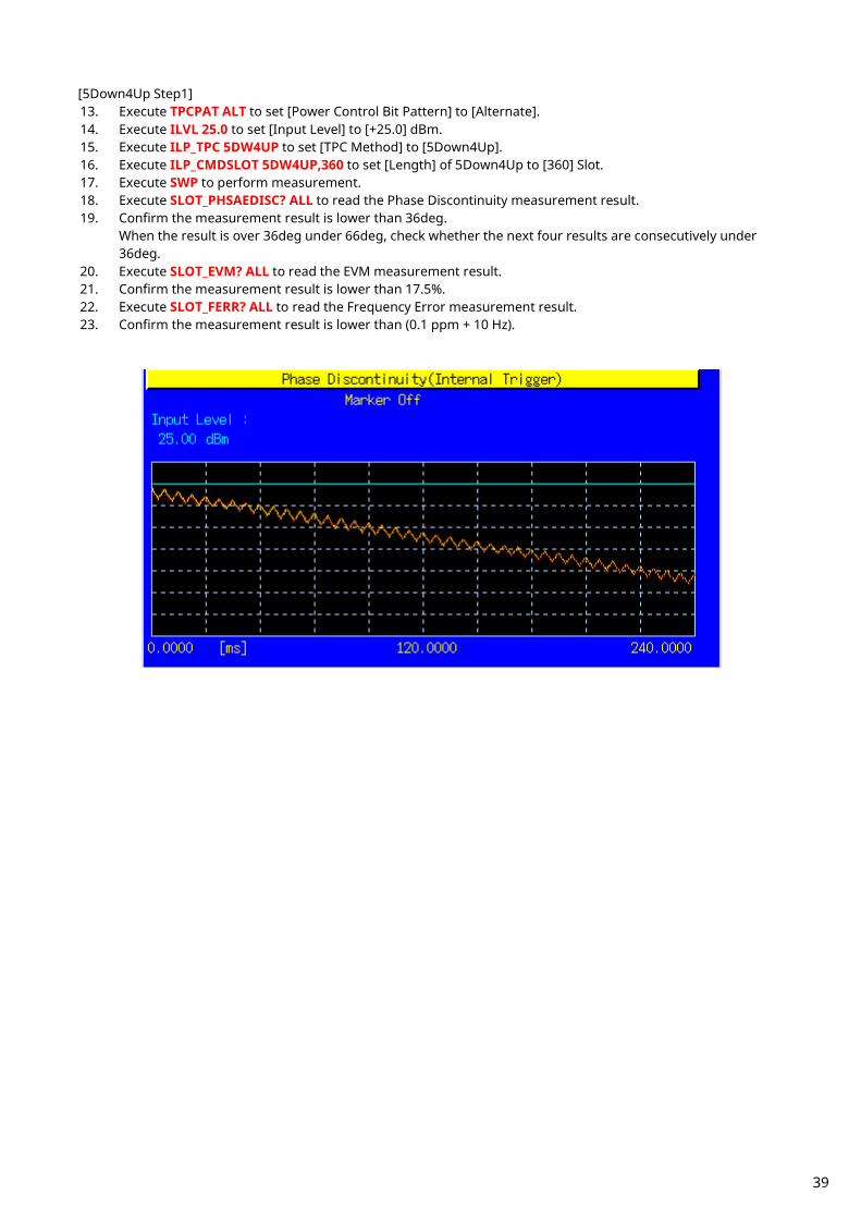
[5Down4Up Step1] 13. Execute TPCPAT ALT to set [Power Control Bit Pattern] to [Alternate]. 14. Execute ILVL 25.0 to set [Input Level] to [+25.0] dBm. 15. Execute ILP_TPC 5DW4UP to set [TPC Method] to [5Down4Up]. 16. Execute ILP_CMDSLOT 5DW4UP,360 to set [Length] of 5Down4Up to [360] Slot. 17. Execute SWP to perform measurement. 18. Execute SLOT_PHSAEDISC? ALL to read the Phase Discontinuity measurement result. 19. Confirm the measurement result is lower than 36deg.
When the result is over 36deg under 66deg, check whether the next four results are consecutively under 36deg.
20. Execute SLOT_EVM? ALL to read the EVM measurement result. 21. Confirm the measurement result is lower than 17.5%. 22. Execute SLOT_FERR? ALL to read the Frequency Error measurement result. 23. Confirm the measurement result is lower than (0.1 ppm + 10 Hz).
39

[5Down4Up Step2] 24. Execute TPCPAT ALT to set [Power Control Bit Pattern] to [Alternate]. 25. Execute ILVL -15.0 to set [Input Level] to [–15.0] dBm. 26. Execute ILP_TPC 5DW4UP to set [TPC Method] to [5Down4Up]. 27. Execute ILP_CMDSLOT 5DW4UP,360 to set [Length] of 5Down4Up to [360] Slot. 28. Execute SWP to perform measurement. 29. Execute SLOT_PHSAEDISC? ALL to read the Phase Discontinuity measurement result. 30. Confirm the measurement result is lower than 36deg.
When the result is over 36deg and under 66deg, check whether the next four results are consecutively under 36deg.
31. Execute SLOT_EVM? ALL to read the EVM measurement result. 32. Confirm the measurement result is lower than 17.5%. 33. Execute SLOT_FERR? ALL to read the Frequency Error measurement result. 34. Confirm the measurement result is lower than (0.1 ppm + 10 Hz).
40

[5Up4Down Step1] 35. Execute TPCPAT ALT to set [Power Control Bit Pattern] to [Alternate]. 36. Execute ILVL -15.0 to set [Input Level] to [–15.0] dBm. 37. Execute ILP_TPC 5UP4DW to set [TPC Method] to [5Up4Down]. 38. Execute ILP_CMDSLOT 5UP4DW,360 to set [Length] of 5Up4Down to [360] Slot. 39. Execute SWP to perform measurement. 40. Execute SLOT_PHSAEDISC? ALL to read the Phase Discontinuity measurement result. 41. Confirm the measurement result is lower than 36deg.
When the result is over 36deg and under 66deg, check whether the next four results are consecutively under 36deg.
42. Execute SLOT_EVM? ALL to read the EVM measurement result. 43. Confirm the measurement result is lower than 17.5%. 44. Execute SLOT_FERR? ALL to read the Frequency Error measurement result. 45. Confirm the measurement result is lower than (0.1 ppm + 10 Hz).
41

[5Up4Down Step2] 46. Execute TPCPAT ALT to set [Power Control Bit Pattern] to [Alternate]. 47. Execute ILVL 25.0 to set [Input Level] to [+25.0] dBm. 48. Execute ILP_TPC 5UP4DW to set [TPC Method] to [5Up4Down]. 49. Execute ILP_CMDSLOT 5UP4DW,360 to set [Length] of 5Up4Down to [360] Slot. 50. Execute SWP to perform measurement. 51. Execute SLOT_PHSAEDISC? ALL to read the Phase Discontinuity measurement result. 52. Confirm the measurement result is lower than 36deg.
When the result is over 36deg and under 66deg, check whether the next four results are consecutively under 36deg.
53. Confirm the measurement result is lower than 17.5%. 54. Execute SLOT_FERR? ALL to read the Frequency Error measurement result. 55. Confirm the measurement result is lower than (0.1 ppm + 10 Hz).
42

1.6. Other Measurements 1.6.1. 5.4.4 Out-of-synchronization of output power.
5.4.4AOut-of-synchronization handling of output power for a UE which supports type1 for DCH
This measurement requires an exact time change. We recommend automated measurement using a PC controller.
1. Execute CALLDROP OFF to set [Call Drop] to [Off]. 2. Execute UETIM_T313 15 to set [T313] to [15] s. 3. Execute UETIM_N313 200 to set [N313] to [200]. 4. Turn on the UE to execute Registration. 5. Connect with Test Loop Mode1. 6. Execute ILVL 25.0 to set [Input Level] to [25.0] dBm. 7. Execute TPCPAT ALL1 to set [Power Control Bit Pattern] to [ALL1]. 8. Execute OLVL -61.0 to set [Output Level] to [–61.0] dBm. 9. Execute AWGNLVL ON to set [AWGN Level] to [On].
10. Execute AWGNPWR 1.0 to set [Ior/Ioc ] to [-1.0] dB. 11. Execute ALLMEASITEMS ON,1,OFF,1,OFF,1OFF,1,OFF,1,OFF,1,OFF,1,OFF,OFF to set [Power Measurement]
to [On] and to set [Average Count] of Power measurement to [1] time.
[Step A] 12. (In case of 5.4.4) Execute DDPCHPWR -16.6 to set [DPCH_Ec/Ior] to [–16.6] dB.
(In case of 5.4.4A) Execute DDPCHPWR -19.6 to set [DPCH_Ec/Ior] to [–19.6] dB. 13. Execute SWP to perform power measurement. 14. Execute AVG_POWER? to read the power measurement result. 15. Confirm the Maximum Output Power.
43
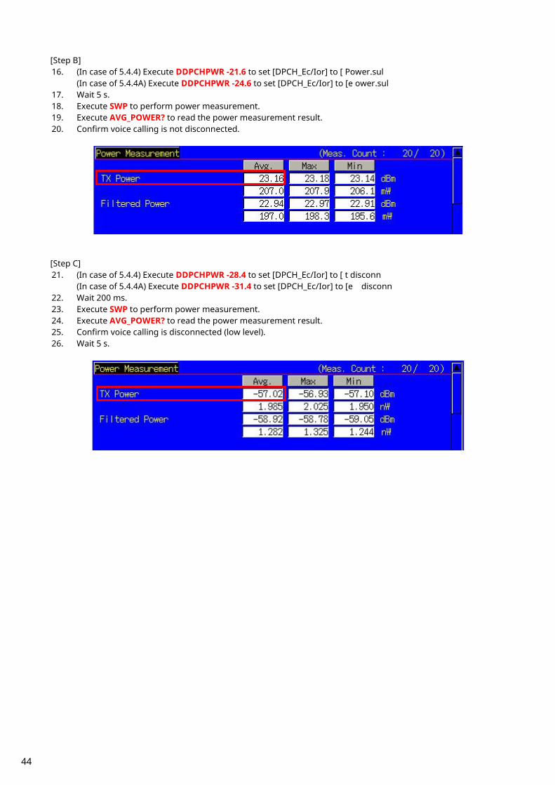
[Step B] 16. (In case of 5.4.4) Execute DDPCHPWR -21.6 to set [DPCH_Ec/Ior] to [ Power.sul
(In case of 5.4.4A) Execute DDPCHPWR -24.6 to set [DPCH_Ec/Ior] to [e ower.sul 17. Wait 5 s. 18. Execute SWP to perform power measurement. 19. Execute AVG_POWER? to read the power measurement result. 20. Confirm voice calling is not disconnected.
[Step C] 21. (In case of 5.4.4) Execute DDPCHPWR -28.4 to set [DPCH_Ec/Ior] to [ t disconn
(In case of 5.4.4A) Execute DDPCHPWR -31.4 to set [DPCH_Ec/Ior] to [e disconn 22. Wait 200 ms. 23. Execute SWP to perform power measurement. 24. Execute AVG_POWER? to read the power measurement result. 25. Confirm voice calling is disconnected (low level). 26. Wait 5 s.
44
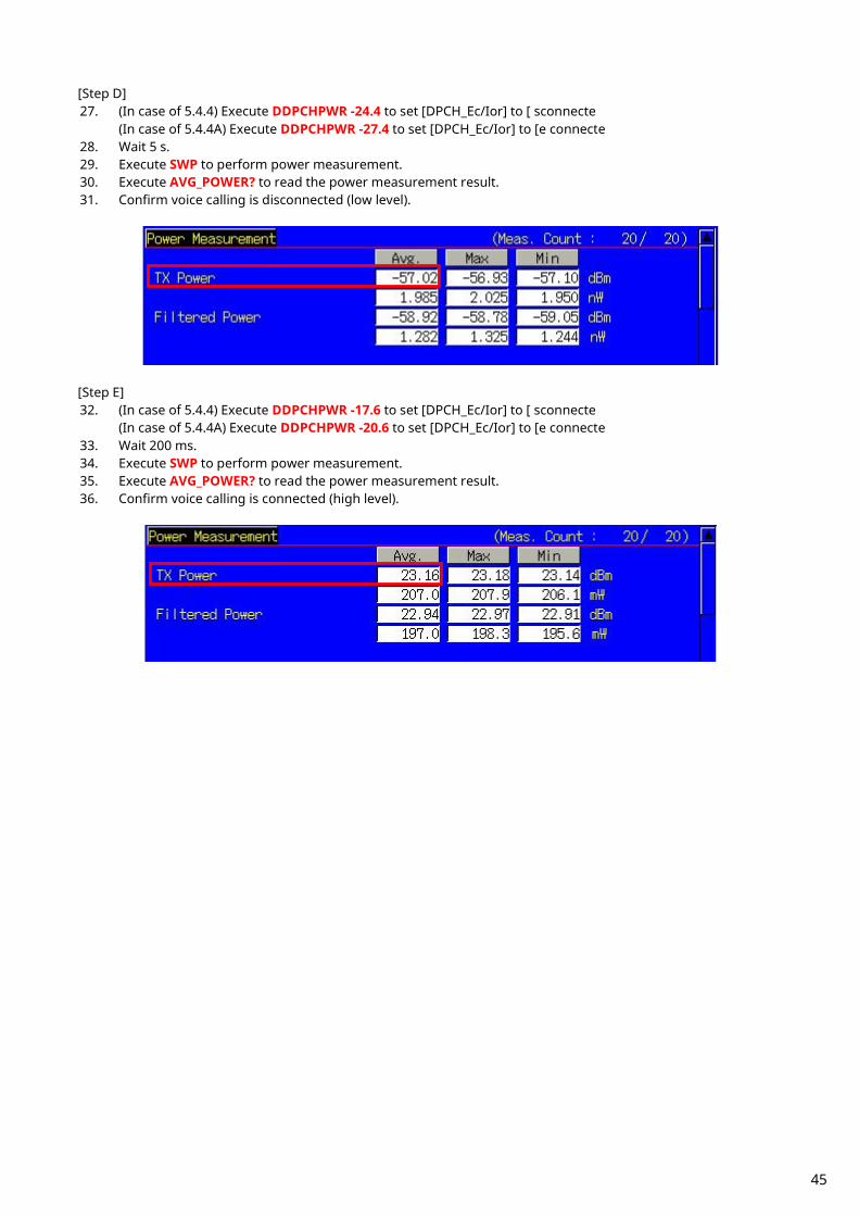
[Step D] 27. (In case of 5.4.4) Execute DDPCHPWR -24.4 to set [DPCH_Ec/Ior] to [ sconnecte
(In case of 5.4.4A) Execute DDPCHPWR -27.4 to set [DPCH_Ec/Ior] to [e connecte 28. Wait 5 s. 29. Execute SWP to perform power measurement. 30. Execute AVG_POWER? to read the power measurement result. 31. Confirm voice calling is disconnected (low level).
[Step E] 32. (In case of 5.4.4) Execute DDPCHPWR -17.6 to set [DPCH_Ec/Ior] to [ sconnecte
(In case of 5.4.4A) Execute DDPCHPWR -20.6 to set [DPCH_Ec/Ior] to [e connecte 33. Wait 200 ms. 34. Execute SWP to perform power measurement. 35. Execute AVG_POWER? to read the power measurement result. 36. Confirm voice calling is connected (high level).
45
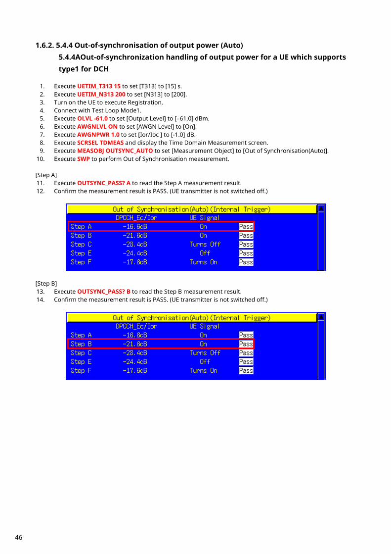
1.6.2. 5.4.4 Out-of-synchronisation of output power (Auto) 5.4.4AOut-of-synchronization handling of output power for a UE which supports type1 for DCH
1. Execute UETIM_T313 15 to set [T313] to [15] s. 2. Execute UETIM_N313 200 to set [N313] to [200]. 3. Turn on the UE to execute Registration. 4. Connect with Test Loop Mode1. 5. Execute OLVL -61.0 to set [Output Level] to [–61.0] dBm. 6. Execute AWGNLVL ON to set [AWGN Level] to [On]. 7. Execute AWGNPWR 1.0 to set [Ior/Ioc ] to [-1.0] dB. 8. Execute SCRSEL TDMEAS and display the Time Domain Measurement screen. 9. Execute MEASOBJ OUTSYNC_AUTO to set [Measurement Object] to [Out of Synchronisation(Auto)].
10. Execute SWP to perform Out of Synchronisation measurement. [Step A] 11. Execute OUTSYNC_PASS? A to read the Step A measurement result. 12. Confirm the measurement result is PASS. (UE transmitter is not switched off.)
[Step B] 13. Execute OUTSYNC_PASS? B to read the Step B measurement result. 14. Confirm the measurement result is PASS. (UE transmitter is not switched off.)
46
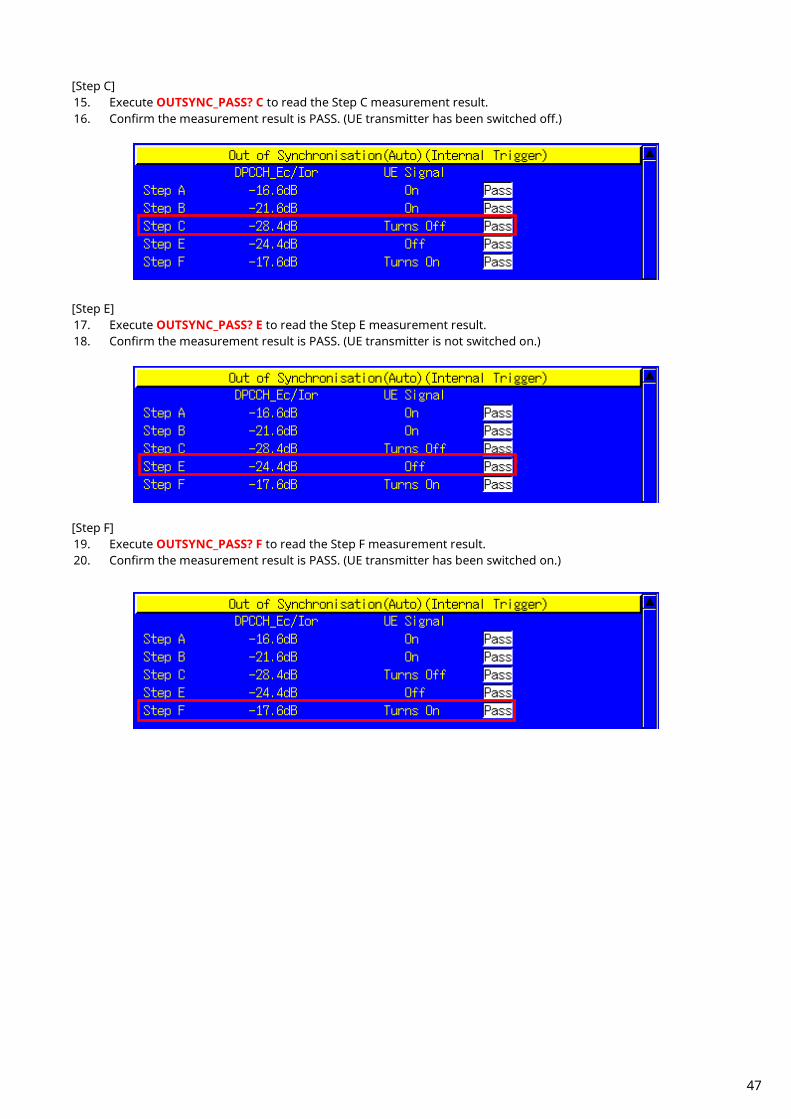
[Step C] 15. Execute OUTSYNC_PASS? C to read the Step C measurement result. 16. Confirm the measurement result is PASS. (UE transmitter has been switched off.)
[Step E] 17. Execute OUTSYNC_PASS? E to read the Step E measurement result. 18. Confirm the measurement result is PASS. (UE transmitter is not switched on.)
[Step F] 19. Execute OUTSYNC_PASS? F to read the Step F measurement result. 20. Confirm the measurement result is PASS. (UE transmitter has been switched on.)
47
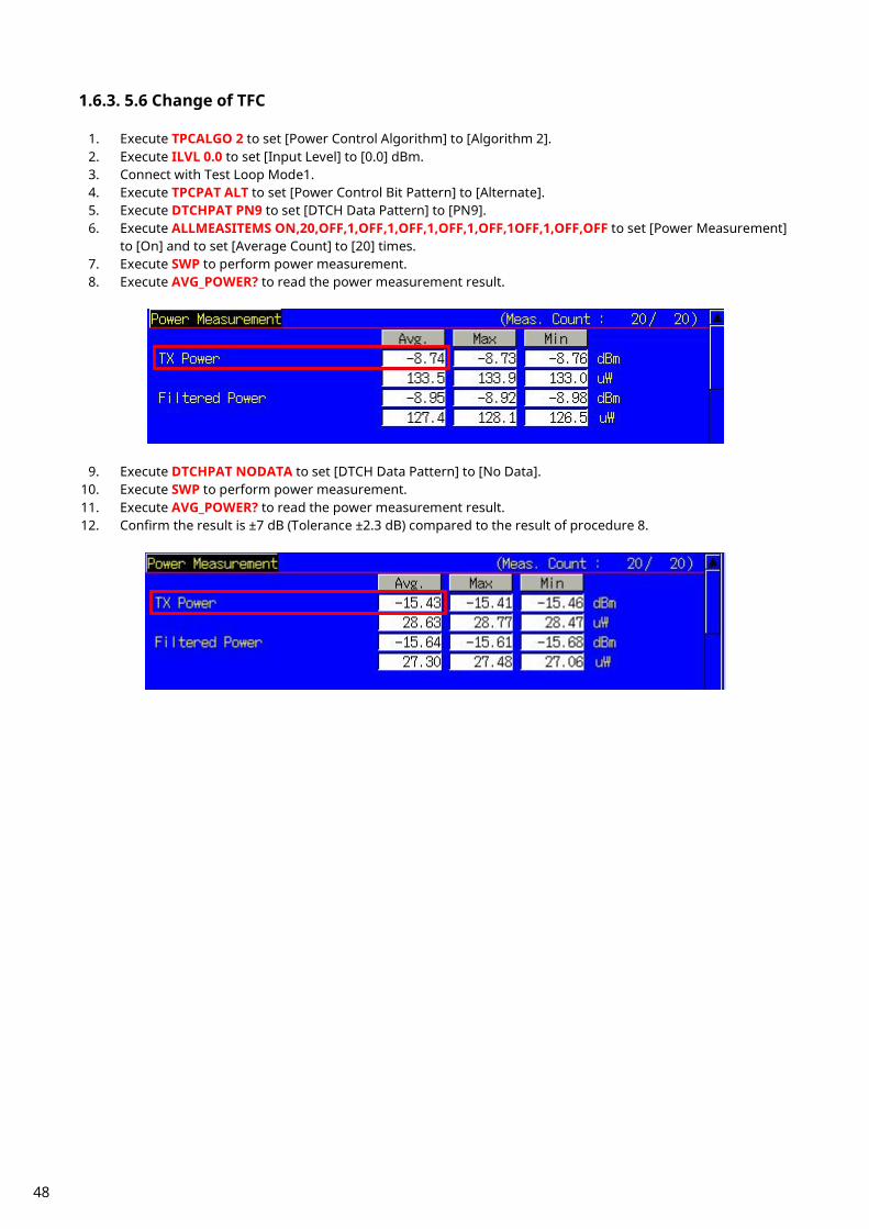
1.6.3. 5.6 Change of TFC
1. Execute TPCALGO 2 to set [Power Control Algorithm] to [Algorithm 2]. 2. Execute ILVL 0.0 to set [Input Level] to [0.0] dBm. 3. Connect with Test Loop Mode1. 4. Execute TPCPAT ALT to set [Power Control Bit Pattern] to [Alternate]. 5. Execute DTCHPAT PN9 to set [DTCH Data Pattern] to [PN9]. 6. Execute ALLMEASITEMS ON,20,OFF,1,OFF,1,OFF,1,OFF,1,OFF,1OFF,1,OFF,OFF to set [Power Measurement]
to [On] and to set [Average Count] to [20] times. 7. Execute SWP to perform power measurement. 8. Execute AVG_POWER? to read the power measurement result.
9. Execute DTCHPAT NODATA to set [DTCH Data Pattern] to [No Data]. 10. Execute SWP to perform power measurement. 11. Execute AVG_POWER? to read the power measurement result. 12. Confirm the result is ±7 dB (Tolerance ±2.3 dB) compared to the result of procedure 8.
48
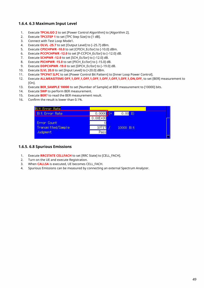
1.6.4. 6.3 Maximum Input Level
1. Execute TPCALGO 2 to set [Power Control Algorithm] to [Algorithm 2]. 2. Execute TPCSTEP 1 to set [TPC Step Size] to [1 dB]. 3. Connect with Test Loop Mode1. 4. Execute OLVL -25.7 to set [Output Level] to [–25.7] dBm. 5. Execute CPICHPWR -10.0 to set [CPICH_Ec/Ior] to [-10.0] dBm. 6. Execute PCCPCHPWR -12.0 to set [P-CCPCH_Ec/Ior] to [–12.0] dB. 7. Execute SCHPWR -12.0 to set [SCH_Ec/Ior] to [–12.0] dB. 8. Execute PICHPWR -15.0 to set [PICH_Ec/Ior] to [–15.0] dB. 9. Execute DDPCHPWR -19.0 to set [DPCH_Ec/Ior] to [–19.0] dB.
10. Execute ILVL 20.0 to set [Input Level] to [+20.0] dBm. 11. Execute TPCPAT ILPC to set [Power Control Bit Pattern] to [Inner Loop Power Control]. 12. Execute ALLMEASITEMS OFF,1,OFF,1,OFF,1,OFF,1,OFF,1,OFF,1,OFF,1,ON,OFF, to set [BER] measurement to
[On]. 13. Execute BER_SAMPLE 10000 to set [Number of Sample] at BER measurement to [10000] bits. 14. Execute SWP to perform BER measurement. 15. Execute BER? to read the BER measurement result. 16. Confirm the result is lower than 0.1%.
1.6.5. 6.8 Spurious Emissions
1. Execute RRCSTATE CELLFACH to set [RRC State] to [CELL_FACH]. 2. Turn on the UE and execute Registration. 3. When CALLSA is executed, UE becomes CELL_FACH. 4. Spurious Emissions can be measured by connecting an external Spectrum Analyzer.
49

1.6.6. 7.2 Demodulation in Static Propagation Condition The following measurement example is for a User bit rate of 12.2 kbps. Measurement can be performed in the same way for 64, 144, and 384 kbps by changing measurement parameters.
1. Execute TESTMODE MODE2 to set [Test Loop Mode] to [Mode 2]. 2. Execute MAXRATE 12.2 to set [Prioritized Ribs DL Max. Rate] to [12.2 kbps]. 3. Execute TPCSTEP 1 to set [TPC Step Size] to [1 dB]. 4. Connect with Test Loop Mode2. 5. Execute OLVL -60.7 to set [Output Level] to [–60.7] dBm. 6. Execute AWGNLVL ON to set [AWGN Level] to [On]. 7. Execute AWGNPWR -0.7 to set [AWGN Level] to [–0.7] dB. 8. Execute CPICHPWR -10.0 to set [CPICH_Ec/Ior] to [–10.0] dB. 9. Execute PCCPCHPWR -12.0 to set [P-CCPCH_Ec/Ior] to [–12.0] dB.
10. Execute SCHPWR -12.0 to set [SCH_Ec/Ior] to [–12.0] dB. 11. Execute PICHPWR -15.0 to set [PICH_Ec/Ior] to [–15.0] dB. 12. Execute DDPCHPWR -16.5 to set [DPCH_Ec/Ior] to [–16.5] dB. 13. Execute ALLMEASITEMS OFF,1,OFF,1,OFF,1,OFF,1,OFF,1,OFF,1,OFF,1,OFF,ON, to set [BLER] measurement
to [On]. 14. Execute BLER_SAMPLE 1000 to set [Number of Sample] at BLER measurement to [1000] Block. 15. Execute SWP to perform BLER measurement. 16. Execute BLER? to read the BLER measurement result. 17. Confirm the result is lower than 0.01.
50
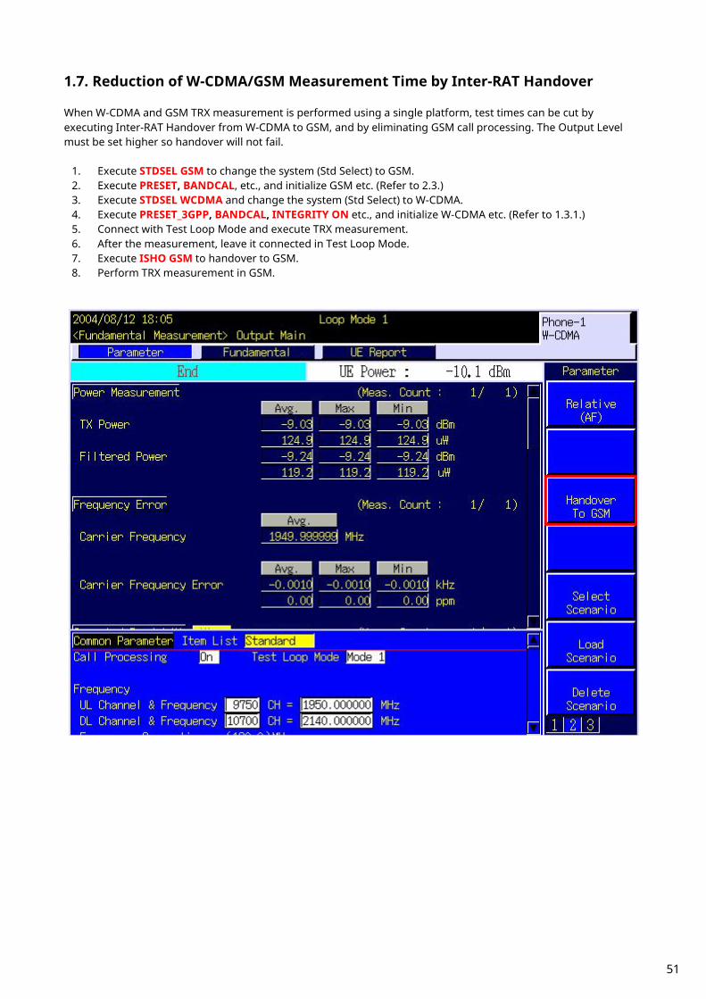
1.7. Reduction of W-CDMA/GSM Measurement Time by Inter-RAT Handover When W-CDMA and GSM TRX measurement is performed using a single platform, test times can be cut by executing Inter-RAT Handover from W-CDMA to GSM, and by eliminating GSM call processing. The Output Level must be set higher so handover will not fail.
1. Execute STDSEL GSM to change the system (Std Select) to GSM. 2. Execute PRESET, BANDCAL, etc., and initialize GSM etc. (Refer to 2.3.) 3. Execute STDSEL WCDMA and change the system (Std Select) to W-CDMA. 4. Execute PRESET_3GPP, BANDCAL, INTEGRITY ON etc., and initialize W-CDMA etc. (Refer to 1.3.1.) 5. Connect with Test Loop Mode and execute TRX measurement. 6. After the measurement, leave it connected in Test Loop Mode. 7. Execute ISHO GSM to handover to GSM. 8. Perform TRX measurement in GSM.
51

1.8. UE Report It is possible to have the UE send a Measurement Report to the tester. An example of how to obtain the CPICH RSCP Report value is shown below. UE Report is sent every 500 ms. Use the second UE Report, because the first UE Report after changing Downlink Level is the value measured before the change.
1. Execute call processing with Test Loop Mode1. 2. Execute MEASREP ON to set [Measurement Report] to [On] to command the UE to send Measurement
Report. 3. Execute OLVL –108 to set [Output Level] to [–108] dBm. 4. Execute CALLRFR to initialize UE Report value. 5. Execute CPICH_RSCP? FLAG and wait until the response becomes 1 (first time). 6. Execute CALLRFR to initialize UE Report value. 7. Execute CPICH_RSCP? FLAG and wait until the response becomes 1 (second time). 8. Execute CPICH_RSCP? to read the CPICH RSCP value. 9. Return to 4 when reading the Report value again.
52

1.9. Functional Test
1.9.1. Voice Call For W-CDMA, AMR12.2 kbps Voice Call can be tested by using Call Processing function. An example of the
Origination test is shown below.
1. Set [Call Processing] of Common Parameter to [On]. 2. Set [Test Loop Mode] of Common Parameter to [Off]. 3. Set [Channel Coding] of Common Parameter to [Voice]. 4. When setting [Integrity Protection] of Call Processing Parameter to [On], confirm the [Authentication Key]
with the SIM value. 5. Call from the UE using any telephone number.
The Call Processing state changes to Origination. The originated telephone number can be checked on the UE Report screen.
6. The Call Processing state changes to Communication. The equipment and UE can communicate with each other.
7. Set [DTCH Data Pattern] at Common Parameter to [Echo] and perform the voice communication test with echo-back.
8. Disconnect the equipment or UE. Press the [End Call] key when disconnecting from the equipment. The Call Processing state changes to UE Release or NW Release.
The result (Pass/Fail) is checked at the Sequence Monitor screen.
53

1.9.2. External Packet Data For W-CDMA, DL 384 kbps and UL64 kbps packet connection can be tested by using the MX88205xC-002 W-CDMA External Packet Data option and Call Processing function. PPP and IP connections are supported. The equipment supports communications between server and Client PCs by supporting the PPP or IP protocols over a wireless interface. Generally, PPP is used for dial-up connections and IP is used for web browsing and sending/receiving mail.
1. Connection without Gateway
<Items to prepare>
UE supporting PPP or IP connection Server PC Client PC Crossover cable for connection between the equipment and Server PC
1. Set 10Base-T [Default Gateway] to [0.0.0.0] at the System Config screen (The Gateway function is off). 2. Reload W-CDMA applications at the Standard Load screen. 3. Set [Call Processing] of Common Parameter to [On]. 4. Set [Test Loop Mode] of Common Parameter to [Off].
Ethernet
IP
TCP/UDP
User Application
Physical Layer
RRC/RLC/MAC
PPP
IP
Physical Layer
RRC/RLC/MAC
PPP
IP
Ethernet
IP
TCP/UDP
User Application
321
654
987
#0*
PC(Client) IP Address: 192.168.20.11
Application Server IP Address: 192.168.20.10
MT8820A
Ethernet(COM)
UE
Airlink
MT8820B
54
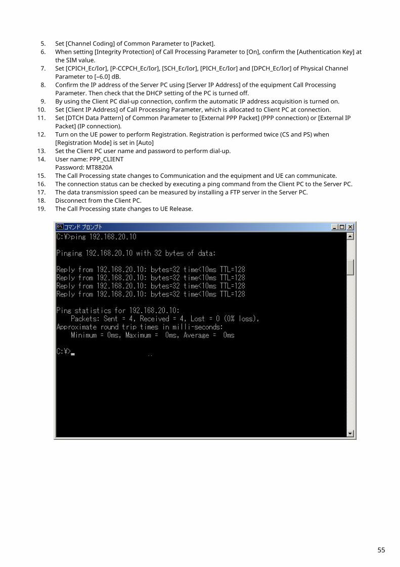
5. Set [Channel Coding] of Common Parameter to [Packet]. 6. When setting [Integrity Protection] of Call Processing Parameter to [On], confirm the [Authentication Key] at
the SIM value. 7. Set [CPICH_Ec/Ior], [P-CCPCH_Ec/Ior], [SCH_Ec/Ior], [PICH_Ec/Ior] and [DPCH_Ec/Ior] of Physical Channel
Parameter to [–6.0] dB. 8. Confirm the IP address of the Server PC using [Server IP Address] of the equipment Call Processing
Parameter. Then check that the DHCP setting of the PC is turned off. 9. By using the Client PC dial-up connection, confirm the automatic IP address acquisition is turned on.
10. Set [Client IP Address] of Call Processing Parameter, which is allocated to Client PC at connection. 11. Set [DTCH Data Pattern] of Common Parameter to [External PPP Packet] (PPP connection) or [External IP
Packet] (IP connection). 12. Turn on the UE power to perform Registration. Registration is performed twice (CS and PS) when
[Registration Mode] is set in [Auto] 13. Set the Client PC user name and password to perform dial-up. 14. User name: PPP_CLIENT
Password: MT8820A 15. The Call Processing state changes to Communication and the equipment and UE can communicate. 16. The connection status can be checked by executing a ping command from the Client PC to the Server PC. 17. The data transmission speed can be measured by installing a FTP server in the Server PC. 18. Disconnect from the Client PC. 19. The Call Processing state changes to UE Release.
55

2. Connection using Gateway Packet communications between different segments can be verified by connecting a Gateway between the equipment and Server PC.
<Items to prepare>
UE supporting PPP or IP connection Server PC Client PC Gateway Straight-through cable for connection between Gateway and the equipment, or Gateway and Server PC
1. Set 10Base-T [Default Gateway] and [Subnet Mask] on System Config screen. At this time, the Default
Gateway address is set to the same IP address as the router at the LAN side. (For example, when the IP address of the LAN side of the router is set to 192.168.20.1, the equipment Default Gateway address must be set to 192.168.20.1).
2. Reload WCDMA applications at the Standard Load screen. 3. Set [Call Processing] of Common Parameter to [On]. 4. Set [Test Loop Mode] of Common Parameter to [Off]. 5. Set [Channel Coding] of Common Parameter to [Packet]. 6. When setting [Integrity] of Call Processing Parameter to [On], confirm the [Authentication Key] at the SIM
value. 7. Set [CPICH_Ec/Ior], [P-CCPCH_Ec/Ior], [SCH_Ec/Ior], [PICH_Ec/Ior] and [DPCH_Ec/Ior] of Physical Channel
Parameter to [–6.0] dB. 8. Set the IP address of the Server PC. The address must be in the same segment as the IP address of WAN side
of router. 9. Set the IP address of the LAN side of the router to the Default Gateway of the Server PC.
10. By using the Client PC dial-up connection, confirm automatic IP address acquisition is turned on. 11. Set [Server IP Address] of Call Processing Parameter to the same IP address as the Default Gateway
(procedure 1 above). 12. Set [Client IP Address] of Call Processing Parameter allocated to the Client PC when connecting. The address
must be in the same segment as the Default Gateway (procedure 1 above). 13. Set [DTCH Data Pattern] of Common Parameter to [External PPP Packet] (PPP connection) or [External IP
Packet] (IP connection). 14. Turn on the UE power and perform Registration. Registration is performed twice (CS and PS) when
[Registration Mode] is set in [Auto]. 15. Set the Client PC user name and password to perform dial-up.
321
654
987
#0*
PC(Client) IP Address: 192.168.20.11
Application Server IP Address: 172.16.10.12
Gateway Address: 172.16.10.1
MT8820A
Ethernet(COM)
UE
Airlink
Default Gateway
IP Address: 192.168.20.1
Router
Ethernet
LAN
WAN
MT8820B
56
16. User name: PPP_CLIENT Password: MT8820A
17. The Call Processing state changes to [Communication] and the equipment and UE can communicate. 18. The connection state can be checked by executing the ping command from the Client PC to the Server PC. 19. The data transmission speed can be measured by setting up an FTP server etc., on the Server PC. 20. Disconnect from the Client PC. 21. The Call Processing state changes to [UE Release].
57

1.9.3. Videophone End-to-end 64-kbps W-CDMA videophone tests can be performed by connecting two units with the MX88205xC-003 W-CDMA Video Phone Test option installed. In addition, this test can be performed using one equipment supporting Parallelphone measurement. <Items to prepare>
Two equipment, or single equipment supporting Parallelphone measurement. Two videophones Crossover cable for connecting equipment and equipment
When using two MT8820B/C
When using single MT8820B/C supporting Parallelphone measurement
MT8820B(1)
MT8820B(2)
Ethernet
Airlink
321
654
987
#0*
Airlink
321
654
987
#0*
UE(1) UE(2)
MT8820B
Ethernet
Airlink
321
654
987
#0*
UE(1)
UE(2)
Airlink
321
654
987
#0*
58
An example of how to perform the end-to-end videophone test is shown below. 1. Use a crossover cable to connect the 10Base-T port 1 of two equipment. When using a single equipment
supporting Parallelphone measurement, connect 10Base-T port 1 and port 2 using a crossover cable. 2. Set [Call Processing] of Common Parameter to [On]. 3. Set [Test Loop Mode] of Common Parameter to [Off]. 4. Set [Channel Coding] of Common Parameter to [Audio & Visual]. 5. Set [DTCH Data Pattern] of Common Parameter to [No Data]. 6. When setting [Integrity] of Call Processing Parameter to [On], confirm the [Authentication Key] using the SIM
value. 7. Press the [Start Call] key of the equipment connected to the UE (1) as shown above. (When using a single
equipment supporting Parallelphone measurement, press the [Start Call] key of UE (1)). 8. Call from UE (2). 9. Answer the call as soon as UE (1) starts ringing.
10. The Call Processing state changes to Communication and the UEs can perform end-to-end communication. 11. Check the video and voice of the two videophones. 12. Press [End Call] of both equipment to disconnect.
The Call Processing state changes to NW Release.
59

1.10. Calibration Measurement Function Refer to the Application Note for UE Calibration about the Calibration Measurement Function.
60

1.11. HSDPA Measurement
1.11.1. Location Registration of Fixed Reference Channel When connecting with HSDPA, Location registration must be performed using Fixed Reference Channel.
1. Execute PRESET_3GPP to preset parameters for 3GPP. 2. Execute CHCODING FIXREFCH to set [Channel Coding] to [Fixed Reference Channel]. 3. Execute INTEGRITY ON to set [Integrity Protection] to [On]. 4. Execute REGMODE COMBINED to set [Registration Mode] to [Combined]. 5. Turn on the UE. 6. Execute CALLSTAT? and wait until the response becomes 2 (= Idle(Regist)).
1.11.2. Connection of Fixed Reference Channel An example of how to connect Fixed Reference Channel after location registration is shown below. (See 1.11.1 Location Registration of Fixed Reference Channel.) [Connection of H-Set1 QPSK]
1. Execute HSHSET HSET1_QPSK to set [H-Set] to [H-Set1(QPSK)]. 2. Execute CALLSA to connect with Fixed Reference Channel. 3. Execute CALLSTAT? and wait until the response becomes 7 (= Test Loop Mode).
[Connection of H-Set1 16QAM]
1. Execute HSHSET HSET1_16QAM to set H-Set to [H-Set1(16QAM)]. 2. Execute CALLSA to connect with Fixed Reference Channel. 3. Execute CALLSTAT? and wait until response becomes 7 (= Test Loop Mode).
1.11.3. Disconnection of Fixed Reference Channel
1. Execute CALLSO to disconnect from Fixed Reference Channel. 2. Execute CALLSTAT? and wait until the response becomes 2 (= Idle(Regist)).
1.11.4. Channel Change by Handover Usually, measurement is performed at three frequency points (L, M, H). In this case, Channel can be quickly switched without reconnection by switching it at handover with a higher output level and βc for UL DPCCH. When a GPIB command is sent during handover, it waits until handover ends.
1. Perform TRX measurement with M channel. 2. Execute CHAN 9613 to handover to L channel. 3. Perform TRX measurement. 4. Execute CHAN 9887 to handover to H channel. 5. Perform TRX measurement.
61
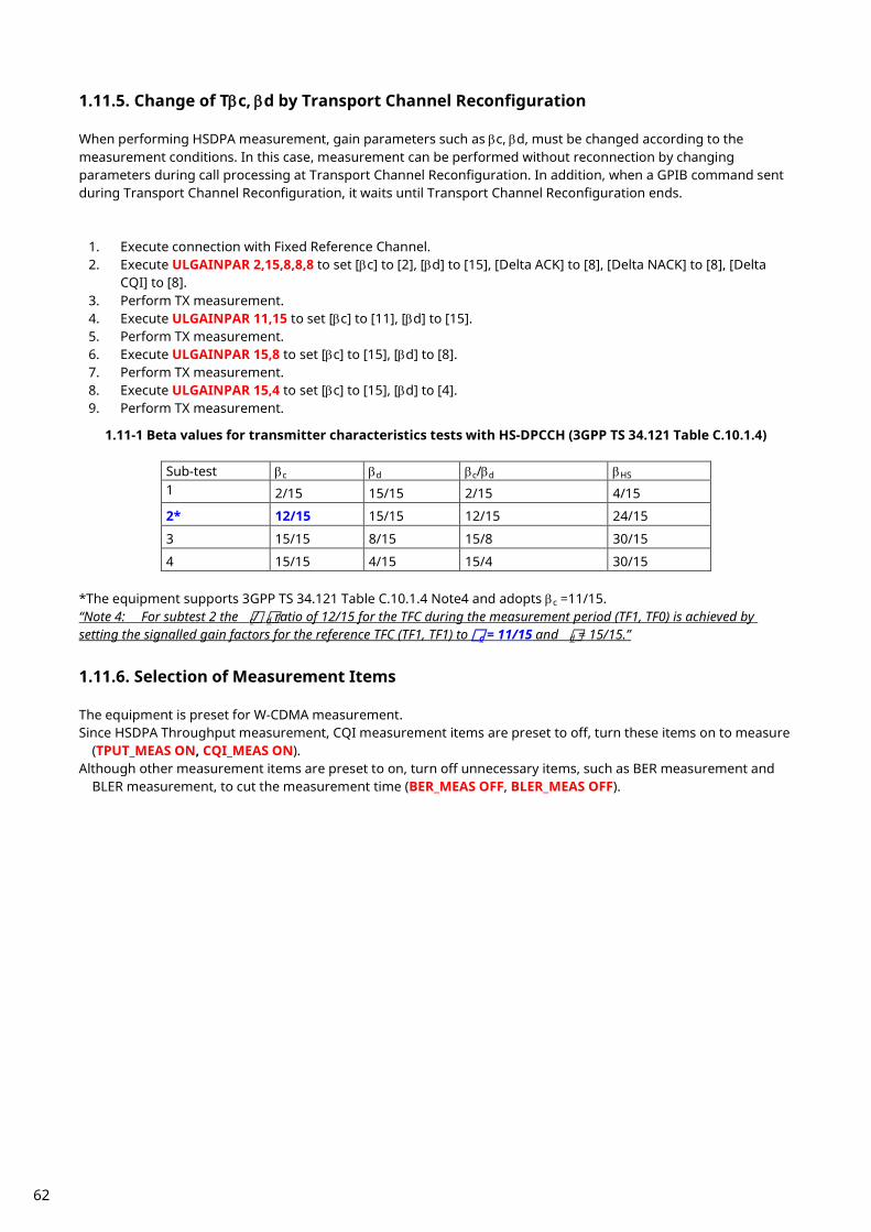
1.11.5. Change of Tβc, βd by Transport Channel Reconfiguration When performing HSDPA measurement, gain parameters such as βc, βd, must be changed according to the measurement conditions. In this case, measurement can be performed without reconnection by changing parameters during call processing at Transport Channel Reconfiguration. In addition, when a GPIB command sent during Transport Channel Reconfiguration, it waits until Transport Channel Reconfiguration ends.
1. Execute connection with Fixed Reference Channel. 2. Execute ULGAINPAR 2,15,8,8,8 to set [βc] to [2], [βd] to [15], [Delta ACK] to [8], [Delta NACK] to [8], [Delta
CQI] to [8]. 3. Perform TX measurement. 4. Execute ULGAINPAR 11,15 to set [βc] to [11], [βd] to [15]. 5. Perform TX measurement. 6. Execute ULGAINPAR 15,8 to set [βc] to [15], [βd] to [8]. 7. Perform TX measurement. 8. Execute ULGAINPAR 15,4 to set [βc] to [15], [βd] to [4]. 9. Perform TX measurement.
1.11-1 Beta values for transmitter characteristics tests with HS-DPCCH (3GPP TS 34.121 Table C.10.1.4)
Sub-test βc βd βc/βd βHS 1 2/15 15/15 2/15 4/15
2* 12/15 15/15 12/15 24/15
3 15/15 8/15 15/8 30/15
4 15/15 4/15 15/4 30/15 *The equipment supports 3GPP TS 34.121 Table C.10.1.4 Note4 and adopts βc =11/15. “Note 4: For subtest 2 the c/ d ratio of 12/15 for the TFC during the measurement period (TF1, TF0) is achieved by setting the signalled gain factors for the reference TFC (TF1, TF1) to c = 11/15 and d = 15/15.”
1.11.6. Selection of Measurement Items The equipment is preset for W-CDMA measurement. Since HSDPA Throughput measurement, CQI measurement items are preset to off, turn these items on to measure
(TPUT_MEAS ON, CQI_MEAS ON). Although other measurement items are preset to on, turn off unnecessary items, such as BER measurement and
BLER measurement, to cut the measurement time (BER_MEAS OFF, BLER_MEAS OFF).
62

1.11.7. 5.2A Maximum Output Power with HS-DPCCH (Release 5 only) 5.2AA Maximum Output Power with HS-DPCCH (Release 6 and later)
1. Execute DDPCHTOFS 6 to set [DPCH Timing Offset] to [6]. 2. Execute CHCODING FIXREFCH to set [Channel Coding] to [Fixed Reference Channel]. 3. Execute SET_PWRPAT HSMAXPWR to set [CQI Feedback Cycle] to [4 ms], [Ack-Nack Repetition Factor] to [3],
[CQI Repetition Factor] to [2], and [TPC Algorithm] to [2]. 4. Connect with Fixed Reference Channel H-Set1 (QPSK). 5. Execute ILVL 24.0 to set [Input Level] to [+24.0] dBm. 6. Execute OLVL -86.0 to set [Output Level] to [–86.0] dBm. 7. Execute TPCPAT ALL1 to set [Power Control Bit Pattern] to [ALL1]. 8. Execute DTCHPAT PN9 to set [DTCH Data Pattern] to [PN9]. 9. Execute PWR_MEAS ON to set [Power measurement] to [On].
10. Execute PWR_AVG 20 to set [Average Count] of Power measurement to [20] times.
[Subtest1] 11. Execute SET_HSDELTA_CQI 8 to set [Delta CQI Setting] to [8]. 12. Execute SET_HSSUBTEST SUBTEST1 to set [Beta C] to [2], [Beta D] to [15], [Delta ACK] to [8], [Delta NACK] to
[8], and [Delta CQI] to [8]. 13. Execute SWP to perform Power measurement. 14. Execute AVG_POWER? to read the Power measurement result. 15. Confirm the measurement result is +24 dBm (Tolerance +1.7/-3.7 dB). [Subtest2] 16. Execute SET_HSDELTA_CQI 8 to set [Delta CQI Setting] to [8]. 17. Execute SET_HSSUBTEST SUBTEST2 to set [Beta C] to [11], [Beta D] to [15], [Delta ACK] to [8], [Delta NACK] to
[8], and [Delta CQI] to [8]. 18. Execute SWP to perform Power measurement. 19. Execute AVG_POWER? to read the Power measurement result. 20. Confirm the measurement result is +24 dBm (Tolerance +1.7/–3.7 dB). . [Subtest3] 21. Execute SET_HSDELTA_CQI 8 to set [Delta CQI Setting] to [8]. 22. Execute SET_HSSUBTEST SUBTEST3 to set [Beta C] to [15], [Beta D] to [8], [Delta ACK] to [8], [Delta NACK] to
[8], and [Delta CQI] to [8]. 23. Execute SWP to perform Power measurement. 24. Execute AVG_POWER? to read the Power measurement result. 25. Confirm the measurement result is the following value
When specification is 5.2A : +23 dBm (Tolerance +2.7/–3.7 dB). When specification is 5.2AA : +23.5 dBm (Tolerance +2.2/–3.7 dB).
63
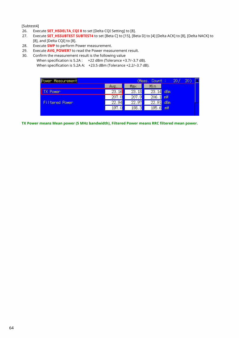
[Subtest4] 26. Execute SET_HSDELTA_CQI 8 to set [Delta CQI Setting] to [8]. 27. Execute SET_HSSUBTEST SUBTEST4 to set [Beta C] to [15], [Beta D] to [4] [Delta ACK] to [8], [Delta NACK] to
[8], and [Delta CQI] to [8]. 28. Execute SWP to perform Power measurement. 29. Execute AVG_POWER? to read the Power measurement result. 30. Confirm the measurement result is the following value
When specification is 5.2A : +22 dBm (Tolerance +3.7/–3.7 dB). When specification is 5.2A A: +23.5 dBm (Tolerance +2.2/–3.7 dB).
TX Power means Mean power (5 MHz bandwidth), Filtered Power means RRC filtered mean power.
64

1.11.8. 5.2C UE Relative Code Domain Power Accuracy (Release 6 and later)
1. Execute DDPCHTOFS 6 to set [DPCH Timing Offset] to [6]. 2. Execute CHCODING FIXREFCH to set [Channel Coding] to [Fixed Reference Channel]. 3. Execute SET_PWRPAT HSPC to set [CQI Feedback Cycle] to [4 ms], [Ack-Nack Repetition Factor] to [1], [CQI
Repetition Factor] to [1], and [TPC Algorithm] to [2]. 4. Connect with Fixed Reference Channel H-Set1 (QPSK). 5. Execute DTCHPAT PN9 to set [DTCH Data Pattern] to [PN9]. 6. Execute OLVL -86.0 to set [Output Level] to [–86.0] dBm. 7. Execute SCRSEL TDMEAS to set [Screen] to [Time Domain Measurement ]. 8. Execute MEASOBJ HSDPCCH_MA to set [Measurement Object] to [HS-DPCCH Modulation Analysis]. 9. Execute HSMA_ITEM CDP to set measurement result of HS-DPCCH (Modulation Analysis) to [CDP Ratio].
10. Execute TDM_RRC OFF to set [RRC Filter] to [Off]. 11. Execute HSSCCH OFF to set [HS-SCCH power] to [Off]. 12. Execute CQIFEEDBACK 0 to set [CQI Feedback Cycle] to [0 ms]. 13. Execute TPCPAT ILPC to set [Power Control Bit Pattern] to [Inner Loop Power Control]. 14. Execute ILVL 0.0 to set [Input Level] to [0.0] dBm. 15. Wait 100 ms until the UE power becomes 0.0 dBm. 16. Execute TPCPAT ALT to set [Power Control Bit Pattern] to [Alternate]. 17. Execute HSSCCH ON to set [HS-SCCH power] to [On]. 18. Execute CQIFEEDBACK 4 to set [CQI Feedback Cycle] to [4 ms]. 19. Execute ILVL 10.0 to set [Input Level] to [10.0] dBm.
65

[Subtest1] 20. Execute SET_HSDELTA_CQI 7 to set [Delta CQI Setting] to [7]. 21. Execute SET_HSSUBTEST SUBTEST1 to set [Beta C] to [2], [Beta D] to [15], [Delta ACK] to [8], [Delta NACK] to
[8], and [Delta CQI] to [7]. 22. Execute SWP to perform Power measurement. 23. Execute CDPPASS? to read the result. Confirm the result is PASS.
When the result is within the Accuracy [dB] in 3GPP TS.34.121 Table 5.2C.4, it means PASS. If not, it means FAIL.
66
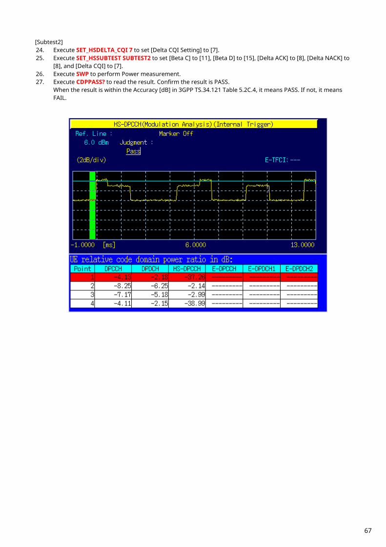
[Subtest2] 24. Execute SET_HSDELTA_CQI 7 to set [Delta CQI Setting] to [7]. 25. Execute SET_HSSUBTEST SUBTEST2 to set [Beta C] to [11], [Beta D] to [15], [Delta ACK] to [8], [Delta NACK] to
[8], and [Delta CQI] to [7]. 26. Execute SWP to perform Power measurement. 27. Execute CDPPASS? to read the result. Confirm the result is PASS.
When the result is within the Accuracy [dB] in 3GPP TS.34.121 Table 5.2C.4, it means PASS. If not, it means FAIL.
67

[Subtest3] 28. Execute SET_HSDELTA_CQI 7 to set [Delta CQI Setting] to [7]. 29. Execute SET_HSSUBTEST SUBTEST3 to set [Beta C] to [15], [Beta D] to [8], [Delta ACK] to [8], [Delta NACK] to
[8], and [Delta CQI] to [7]. 30. Execute SWP to perform Power measurement. 31. Execute CDPPASS? to read the result. Confirm the result is PASS.
When the result is within the Accuracy [dB] in 3GPP TS.34.121 Table 5.2C.4, it means PASS. If not, it means FAIL.
68
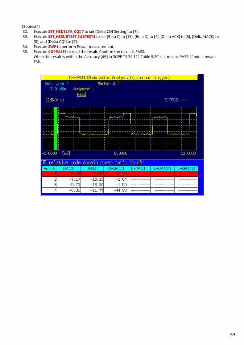
[Subtest4] 32. Execute SET_HSDELTA_CQI 7 to set [Delta CQI Setting] to [7]. 33. Execute SET_HSSUBTEST SUBTEST4 to set [Beta C] to [15], [Beta D] to [4], [Delta ACK] to [8], [Delta NACK] to
[8], and [Delta CQI] to [7]. 34. Execute SWP to perform Power measurement. 35. Execute CDPPASS? to read the result. Confirm the result is PASS.
When the result is within the Accuracy [dB] in 3GPP TS.34.121 Table 5.2C.4, it means PASS. If not, it means FAIL.
69
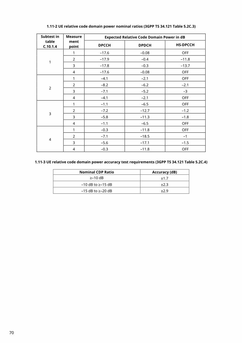
1.11-2 UE relative code domain power nominal ratios (3GPP TS 34.121 Table 5.2C.3)
Subtest in table
C.10.1.4
Measurement point
Expected Relative Code Domain Power in dB
DPCCH DPDCH HS-DPCCH
1
1 –17.6 –0.08 OFF
2 –17.9 –0.4 –11.8
3 –17.8 –0.3 –13.7
4 –17.6 –0.08 OFF
2
1 –4.1 –2.1 OFF
2 –8.2 –6.2 –2.1
3 –7.1 –5.2 –3
4 –4.1 –2.1 OFF
3
1 –1.1 –6.5 OFF
2 –7.2 –12.7 –1.2
3 –5.8 –11.3 –1.8
4 –1.1 –6.5 OFF
4
1 –0.3 –11.8 OFF
2 –7.1 –18.5 –1
3 –5.6 –17.1 –1.5
4 –0.3 –11.8 OFF
1.11-3 UE relative code domain power accuracy test requirements (3GPP TS 34.121 Table 5.2C.4)
Nominal CDP Ratio Accuracy (dB) ≥–10 dB ±1.7
–10 dB to ≥–15 dB ±2.3
–15 dB to ≥–20 dB ±2.9
70
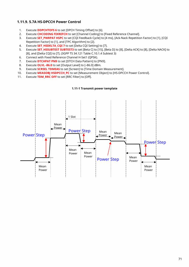
1.11.9. 5.7A HS-DPCCH Power Control
1. Execute DDPCHTOFS 6 to set [DPCH Timing Offset] to [6]. 2. Execute CHCODING FIXREFCH to set [Channel Coding] to [Fixed Reference Channel]. 3. Execute SET_PWRPAT HSPC to set [CQI Feedback Cycle] to [4 ms], [Ack-Nack Repetition Factor] to [1], [CQI
Repetition Factor] to [1], and [TPC Algorithm] to [2]. 4. Execute SET_HSDELTA_CQI 7 to set [Delta CQI Setting] to [7]. 5. Execute SET_HSSUBTEST SUBTEST3 to set [Beta C] to [15], [Beta D] to [8], [Delta ACK] to [8], [Delta NACK] to
[8], and [Delta CQI] to [7]. (3GPP TS 34.121 Table C.10.1.4 Subtest 3) 6. Connect with Fixed Reference Channel H-Set1 (QPSK). 7. Execute DTCHPAT PN9 to set [DTCH Data Pattern] to [PN9]. 8. Execute OLVL -86.0 to set [Output Level] to [–86.0] dBm. 9. Execute SCRSEL TDMEAS to set [Screen] to [Time Domain Measurement].
10. Execute MEASOBJ HSDPCCH_PC to set [Measurement Object] to [HS-DPCCH Power Control]. 11. Execute TDM_RRC OFF to set [RRC Filter] to [Off].
1.11-1 Transmit power template
Power Step Power Step
Power Step
Power Step
Mean Power
Mean Power
Mean Power Mean
Power
Mean Power
Mean Power
Mean Power
Mean Power
1 Slot
71

[TPC_cmd = 0] 12. Execute HSSCCH OFF to set [HS-SCCH power] to [Off]. 13. Execute CQIFEEDBACK 0 to set [CQI Feedback Cycle] to [0 ms]. 14. Execute TPCPAT ILPC to set [Power Control Bit Pattern] to [Inner Loop Power Control]. 15. Execute ILVL 0.0 to set [Input Level] to [0.0] dBm. 16. Wait 100 ms until the UE power becomes 0.0 dBm. 17. Execute TPCPAT ALT to set [Power Control Bit Pattern] to [Alternate]. 18. Execute HSSCCH ON to set [HS-SCCH power] to [On]. 19. Execute CQIFEEDBACK 4 to set [CQI Feedback Cycle] to [4 ms]. 20. Execute ILVL 10.0 to set [Input Level] to [10.0] dBm. 21. Execute OLVL -86.0 to set [Output Level] to [–86.0] dBm. 22. Execute HSPC_CMD 0 to set a template for HS-DPCCH Power Control to [TPC_cmd = 0]. 23. Execute SWP to perform HS-DPCCH measurement. 24. Execute HSPCPASS? to read the HS-DPCCH measurement result. Confirm the result is PASS.
When all Power Step results are within the Allowed Transmitter power step range [dB] in 3GPP TS.34.121 Table 5. 7A.2. it means PASS. If not, it means FAIL.
72

1.11-4 3GPP TS34.121 Table 5.7A.2: Transmitter power test requirements for TPC_cmd=0
Sub-test in table
C.10.1.4
Power step
Nominal Power step size, ∆P [dB]
Rounded Power step size, ∆P [dB]
Transmitter power step
Tolerance [dB]
Allowed Transmitter power step range [dB]
3
1 6.14 6 +/- 2.3 3.7 to 8.44
2 -1.38 -1 +/- 0.6 -1.98 to -0.4
3 -4.76 -5 +/- 2.3 -7.3 to -2.46
41 0 0 +/- 0.6 -0.6 to 0.6
5 4.76 5 +/- 2.3 2.46 to 7.3
6 1.38 1 +/- 0.6 0.4 to 1.98
7 -6.14 -6 +/- 2.3 -8.44 to -3.7
81 0 0 +/- 0.6 -0.6 to 0.6
9 4.76 5 +/- 2.3 2.46 to 7.3
10 -4.76 -5 +/- 2.3 -7.3 to -2.46
111 0 0 +/- 0.6 -0.6 to 0.6
Note 1: Two test points
1.11-2 Transmit power template below max power with TPC_cmd = 0
Subframe n
Subframe n+1
Subframe n+2
Subframe n+3
Subframe n+4
Subframe n+5
ACK/NACK
CQI CQI CQI CQI ACK/NACK
CQI CQI
(1) (2) (3) (4)
(5) (6) (7) (8) (9) (10) (11)
73

[TPC_cmd = 1] 25. Execute ILVL 35.0 to set [Input Level] to [+35.0] dBm. 26. Execute TPCALGO 1 to set [TPC Algorithm] to [1]. 27. Execute TPCPAT ALL1 to set [Power Control Bit Pattern] to [ALL1]. 28. Wait 100 ms until the UE power becomes maximum. 29. Execute HSPC_CMD 1 to set the template for HS-DPCCH Power Control to [TPC_cmd = 1]. 30. Execute SWP to perform HS-DPCCH measurement. 31. Execute HSPCPASS? to read the HS-DPCCH measurement result. Confirm the result is PASS.
When all Power Step results are within the Allowed Transmitter power step range [dB] in 3GPP TS.34.121 Table 5. 7A.2. it means PASS. If not, it means FAIL.
74
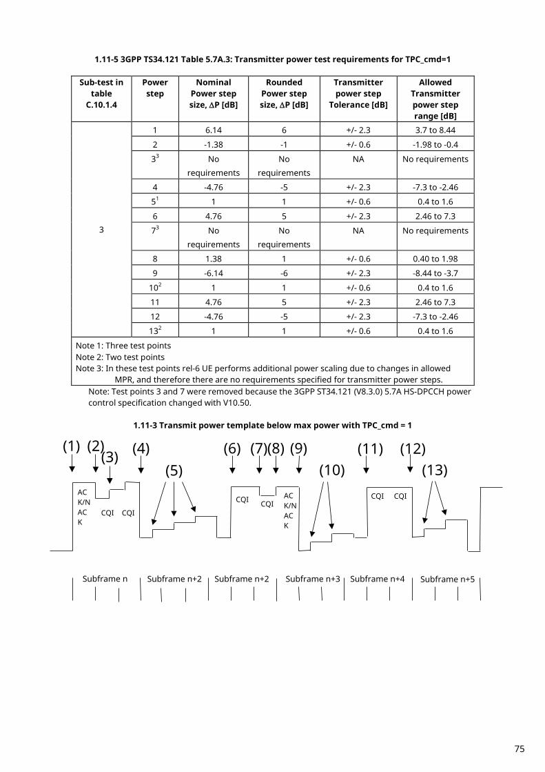
1.11-5 3GPP TS34.121 Table 5.7A.3: Transmitter power test requirements for TPC_cmd=1
Sub-test in table
C.10.1.4
Power step
Nominal Power step size, ∆P [dB]
Rounded Power step size, ∆P [dB]
Transmitter power step
Tolerance [dB]
Allowed Transmitter power step range [dB]
3
1 6.14 6 +/- 2.3 3.7 to 8.44
2 -1.38 -1 +/- 0.6 -1.98 to -0.4
33 No
requirements
No
requirements
NA No requirements
4 -4.76 -5 +/- 2.3 -7.3 to -2.46
51 1 1 +/- 0.6 0.4 to 1.6
6 4.76 5 +/- 2.3 2.46 to 7.3
73 No
requirements
No
requirements
NA No requirements
8 1.38 1 +/- 0.6 0.40 to 1.98
9 -6.14 -6 +/- 2.3 -8.44 to -3.7
102 1 1 +/- 0.6 0.4 to 1.6
11 4.76 5 +/- 2.3 2.46 to 7.3
12 -4.76 -5 +/- 2.3 -7.3 to -2.46
132 1 1 +/- 0.6 0.4 to 1.6
Note 1: Three test points Note 2: Two test points Note 3: In these test points rel-6 UE performs additional power scaling due to changes in allowed
MPR, and therefore there are no requirements specified for transmitter power steps. Note: Test points 3 and 7 were removed because the 3GPP ST34.121 (V8.3.0) 5.7A HS-DPCCH power control specification changed with V10.50.
1.11-3 Transmit power template below max power with TPC_cmd = 1
Subframe n
Subframe n+2
Subframe n+2
Subframe n+3
Subframe n+4
Subframe n+5
ACK/NACK
CQI CQI
CQI CQI ACK/NACK
CQI CQI
(1)
(2) (3)
(4) (5)
(6)
(7)
(8)
(9) (10)
(11)
(12) (13)
75

1.11.10. 5.9A Spectrum Emission Mask with HS-DPCCH
1. Execute DDPCHTOFS 6 to set [DPCH Timing Offset] to [6]. 2. Execute CHCODING FIXREFCH to set [Channel Coding] to [Fixed Reference Channel]. 3. Execute SET_PWRPAT HSMAXPWR to set [CQI Feedback Cycle] to [4 ms], [Ack-Nack Repetition Factor] to [3],
[CQI Repetition Factor] to [2], and [TPC Algorithm] to [2]. 4. Connect with Fixed Reference Channel H-Set1 (QPSK). 5. Execute ILVL 35.0 to set [Input Level] to [+35.0] dBm. 6. Execute OLVL -86.0 to set [Output Level] to [–86.0] dBm. 7. Execute TPCPAT ALL1 to set [Power Control Bit Pattern] to [ALL1]. 8. Execute DTCHPAT PN9 to set [DTCH Data Pattern] to [PN9]. 9. Execute SMASK_MEAS ON to set [Spectrum Emission Mask] measurement to [On].
10. Execute SMASK_AVG 20 to set [Average Count] of SEM measurement to [20] times. [Subtest1] 11. Execute SET_HSDELTA_CQI 8 to set [Delta CQI Setting] to [8]. 12. Execute SET_HSSUBTEST SUBTEST1 to set [Beta C] to [2], [Beta D] to [15], [Delta ACK] to [8], [Delta NACK] to
[8], and [Delta CQI] to [8]. 13. Execute SWP to perform SEM measurement. 14. Execute SMASKPASS? to read the SEM measurement result. Confirm the measurement result is PASS. [Subtest2] 15. Execute SET_HSDELTA_CQI 8 to set [Delta CQI Setting] to [8]. 16. Execute SET_HSSUBTEST SUBTEST2 to set [Beta C] to [11], [Beta D] to [15], [Delta ACK] to [8], [Delta NACK] to
[8], and [Delta CQI] to [8]. 17. Execute SWP to perform SEM measurement. 18. Execute SMASKPASS? to read the SEM measurement result. Confirm the measurement result is PASS. [Subtest3] 19. Execute SET_HSDELTA_CQI 8 to set [Delta CQI Setting] to [8]. 20. Execute SET_HSSUBTEST SUBTEST3 to set [Beta C] to [15], [Beta D] to [8], [Delta ACK] to [8], [Delta NACK] to
[8], and [Delta CQI] to [8]. 21. Execute SWP to perform SEM measurement. 22. Execute SMASKPASS? to read the SEM measurement result. Confirm the measurement result is PASS. [Subtest4] 23. Execute SET_HSDELTA_CQI 8 to set [Delta CQI Setting] to [8]. 24. Execute SET_HSSUBTEST SUBTEST4 to set [Beta C] to [15], [Beta D] to [4], [Delta ACK] to [8], [Delta NACK] to
[8], and [Delta CQI] to [8]. 25. Execute SWP to perform SEM measurement. 26. Execute SMASKPASS? to read the SEM measurement result. Confirm the measurement result is PASS.
76

1.11.11. 5.10A Adjacent Channel Leakage Power Ratio (ACLR) with HS-DPCCH
1. Execute DDPCHTOFS 6 to set [DPCH Timing Offset] to [6]. 2. Execute CHCODING FIXREFCH to set [Channel Coding] to [Fixed Reference Channel]. 3. Execute SET_PWRPAT HSMAXPWR to set [CQI Feedback Cycle] to [4 ms], [Ack-Nack Repetition Factor] to [3],
[CQI Repetition Factor] to [2], and [TPC Algorithm] to [2]. 4. Connect with Fixed Reference Channel H-Set1 (QPSK). 5. Execute ILVL 35.0 to set [Input Level] to [+35.0] dBm. 6. Execute OLVL -86.0 to set [Output Level] to [–86.0] dBm. 7. Execute TPCPAT ALL1 to set [Power Control Bit Pattern] to [ALL1]. 8. Execute DTCHPAT PN9 to set [DTCH Data Pattern] to [PN9]. 9. Execute ADJ_MEAS ON to set [Adjacent Channel Power](ACLR) measurement to [On].
10. Execute ADJ_AVG 20 to set [Average Count] of ACLR measurement to [20] times. [Subtest1] 11. Execute SET_HSDELTA_CQI 8 to set [Delta CQI Setting] to [8]. 12. Execute SET_HSSUBTEST SUBTEST1 to set [Beta C] to [2], [Beta D] to [15], [Delta ACK] to [8], [Delta NACK] to
[8], and [Delta CQI] to [8]. 13. Execute SWP to perform ACLR measurement. 14. Execute AVG_MODPWR? LOW10, AVG_MODPWR? LOW5, AVG_MODPWR? UP5, AVG_MODPWR? UP10 to
read the ACLR measurement results. 15. Compare the measurement result with the table below. [Subtest2] 16. Execute SET_HSDELTA_CQI 8 to set [Delta CQI Setting] to [8]. 17. Execute SET_HSSUBTEST SUBTEST1 to set [Beta C] to [11], [Beta D] to [15], [Delta ACK] to [8], [Delta NACK] to
[8], and [Delta CQI] to [8]. 18. Execute SWP to perform ACLR measurement. 19. Execute AVG_MODPWR? LOW10, AVG_MODPWR? LOW5, AVG_MODPWR? UP5, AVG_MODPWR? UP10 to
read the ACLR measurement results. 20. Compare the measurement result with the table below. [Subtest3] 21. Execute SET_HSDELTA_CQI 8 to set [Delta CQI Setting] to [8]. 22. Execute SET_HSSUBTEST SUBTEST1 to set [Beta C] to [15], [Beta D] to [8], [Delta ACK] to [8], [Delta NACK] to
[8], and [Delta CQI] to [8]. 23. Execute SWP to perform ACLR measurement. 24. Execute AVG_MODPWR? LOW10, AVG_MODPWR? LOW5, AVG_MODPWR? UP5, AVG_MODPWR? UP10 to
read the ACLR measurement results. 25. Compare the measurement result with the table below.
77

[Subtest4] 26. Execute SET_HSDELTA_CQI 8 to set [Delta CQI Setting] to [8]. 27. Execute SET_HSSUBTEST SUBTEST1 to set [Beta C] to [15], [Beta D] to [4], [Delta ACK] to [8], [Delta NACK] to
[8], and [Delta CQI] to [8]. 28. Execute SWP to perform ACLR measurement. 29. Execute AVG_MODPWR? LOW10, AVG_MODPWR? LOW5, AVG_MODPWR? UP5, AVG_MODPWR? UP10 to
read the ACLR measurement results. 30. Compare the measurement result with the table below.
1.11-6 UE ACLR (3GPP TS 34.121 Table 5.10A.3)
Power Class UE Channel ACLR Limit 3 +5 MHz or −5 MHz 32.2 dB
3 +10 MHz or −10 MHz 42.2 dB
78
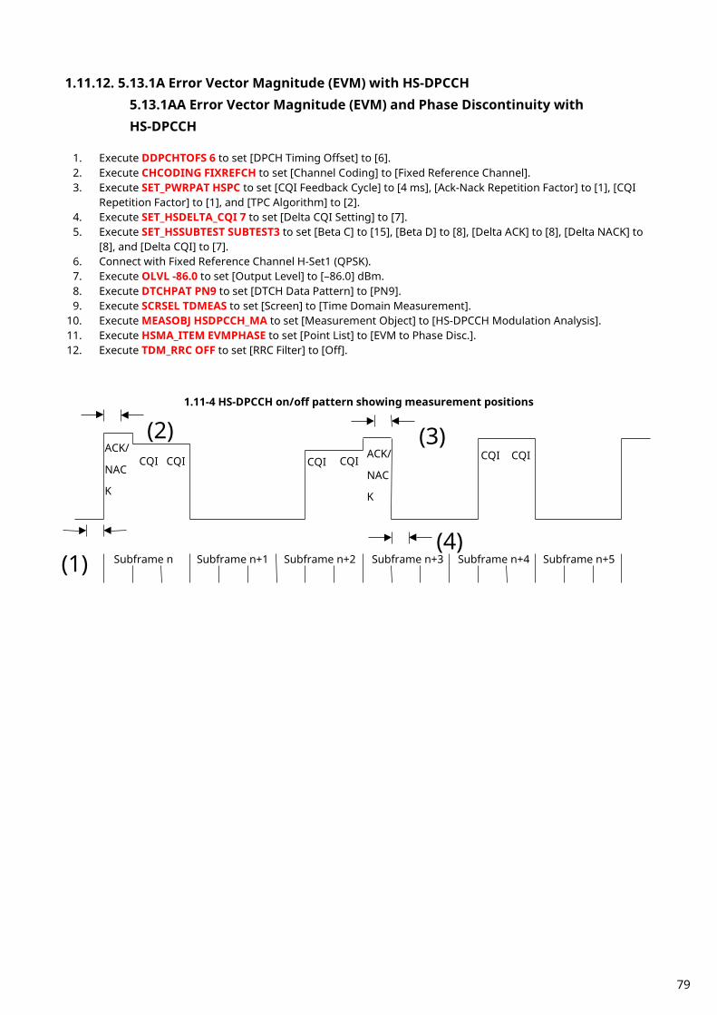
1.11.12. 5.13.1A Error Vector Magnitude (EVM) with HS-DPCCH 5.13.1AA Error Vector Magnitude (EVM) and Phase Discontinuity with HS-DPCCH
1. Execute DDPCHTOFS 6 to set [DPCH Timing Offset] to [6]. 2. Execute CHCODING FIXREFCH to set [Channel Coding] to [Fixed Reference Channel]. 3. Execute SET_PWRPAT HSPC to set [CQI Feedback Cycle] to [4 ms], [Ack-Nack Repetition Factor] to [1], [CQI
Repetition Factor] to [1], and [TPC Algorithm] to [2]. 4. Execute SET_HSDELTA_CQI 7 to set [Delta CQI Setting] to [7]. 5. Execute SET_HSSUBTEST SUBTEST3 to set [Beta C] to [15], [Beta D] to [8], [Delta ACK] to [8], [Delta NACK] to
[8], and [Delta CQI] to [7]. 6. Connect with Fixed Reference Channel H-Set1 (QPSK). 7. Execute OLVL -86.0 to set [Output Level] to [–86.0] dBm. 8. Execute DTCHPAT PN9 to set [DTCH Data Pattern] to [PN9]. 9. Execute SCRSEL TDMEAS to set [Screen] to [Time Domain Measurement].
10. Execute MEASOBJ HSDPCCH_MA to set [Measurement Object] to [HS-DPCCH Modulation Analysis]. 11. Execute HSMA_ITEM EVMPHASE to set [Point List] to [EVM to Phase Disc.]. 12. Execute TDM_RRC OFF to set [RRC Filter] to [Off].
1.11-4 HS-DPCCH on/off pattern showing measurement positions
Subframe n
Subframe n+1
Subframe n+2
Subframe n+3
Subframe n+4
Subframe n+5
ACK/ NAC K
CQI CQI CQI CQI ACK/ NAC
K
CQI CQI
(1)
(2)
(3)
(4)
79
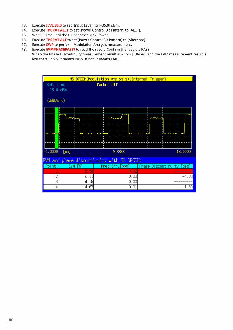
13. Execute ILVL 35.0 to set [Input Level] to [+35.0] dBm. 14. Execute TPCPAT ALL1 to set [Power Control Bit Pattern] to [ALL1]. 15. Wait 300 ms until the UE becomes Max Power. 16. Execute TPCPAT ALT to set [Power Control Bit Pattern] to [Alternate]. 17. Execute SWP to perform Modulation Analysis measurement. 18. Execute EVMPHASEPASS? to read the result. Confirm the result is PASS.
When the Phase Discontinuity measurement result is within [±36deg] and the EVM measurement result is less than 17.5%, it means PASS. If not, it means FAIL.
80

19. Execute TPCPAT ILPC to set [Power Control Bit Pattern] to [Inner Loop Power Control]. 20. Execute HSSCCH OFF to set [HS-SCCH power] to [Off]. 21. Execute CQIFEEDBACK 0 to set [CQI Feedback Cycle] to [0 ms]. 22. Execute ILVL -18.0 to set [Input Level] to [–18.0] dBm. 23. Wait 200 ms until the UE power becomes [–18.0] dBm. 24. Execute TPCPAT ALT to set [Power Control Bit Pattern] to [Alternate]. 25. Execute HSSCCH ON to set [HS-SCCH power] to [On]. 26. Execute CQIFEEDBACK 4 to set [CQI Feedback Cycle] to [4 ms]. 27. Execute ILVL -10.0 to set [Input Level] to [–10.0] dBm. 28. Execute SWP to perform Modulation Analysis measurement. 29. Execute EVMPHASEPASS? to read the result. Confirm the result is PASS.
When the Phase Discontinuity measurement result is within [±36deg] and the EVM measurement result is less than 17.5%, it means PASS. If not, it means FAIL.
81

1.11.13. 5.13.2A Relative Code Domain Error with HS-DPCCH
1. Execute DDPCHTOFS 6 to set [DPCH Timing Offset] to [6]. 2. Execute CHCODING FIXREFCH to set [Channel Coding] to [Fixed Reference Channel]. 3. Execute SET_PWRPAT HSMAXPWR to set [CQI Feedback Cycle] to [4 ms], [Ack-Nack Repetition Factor] to [3],
[CQI Repetition Factor] to [2], and [TPC Algorithm] to [2]. 4. Connect with Fixed Reference Channel H-Set1 (QPSK). 5. Execute ILVL 35.0 to set [Input Level] to [+35.0] dBm. 6. Execute OLVL -86.0 to set [Output Level] to [–86.0] dBm. 7. Execute TPCPAT ALL1 to set [Power Control Bit Pattern] to [ALL1]. 8. Execute DTCHPAT PN9 to set [DTCH Data Pattern] to [PN9]. 9. Execute RCDE_MEAS ON to set [RCDE] measurement to [On].
10. Execute RCDE_AVG 20 to set [Average Count] of RCDE measurement to [20] times. When input level set to max power [Subtest1] 11. Execute SET_HSDELTA_CQI 8 to set [Delta CQI Setting] to [8]. 12. Execute SET_HSSUBTEST SUBTEST1 to set [Beta C] to [2], [Beta D] to [15], [Delta ACK] to [8], [Delta NACK] to
[8], and [Delta CQI] to [8]. 13. Execute SWP to perform RCDE measurement. 14. Execute AVG_DPCCHECDP? to read the ECDP - DPCCH measurement result. 15. Execute AVG_DPDCHECDP? to read the ECDP - DPDCH measurement result. 16. Execute AVG_HSDPCCHECDP? to read the ECDP - HS-DPCCH measurement result. 17. Execute AVG_DPCCHRCDE? to read the Relative Code Domain Error - DPCCH measurement result. 18. Execute AVG_DPDCHRCDE? to read the Relative Code Domain Error - DPDCH measurement result. 19. Execute AVG_HSDPCCHRCDE? to read the Relative Code Domain Error - HS-DPCCH measurement result. 20. Confirm the Relative Code Domain Error is
Relative Code Domain Error ≤ –15.5 dB, when –21 dB < ECDP and Relative Code Domain Error ≤ –36.5 – ECDP, when –30 dB ≤ ECDP ≤ –21dB.
[Subtest3] 21. Execute SET_HSDELTA_CQI 8 to set [Delta CQI Setting] to [8]. 22. Execute SET_HSSUBTEST SUBTEST3 to set [Beta C] to [15], [Beta D] to [8], [Delta ACK] to [8], [Delta NACK] to
[8], and [Delta CQI] to [8]. 23. Execute SWP to perform RCDE measurement. 24. Execute AVG_DPCCHECDP? to read the ECDP - DPCCH measurement result. 25. Execute AVG_DPDCHECDP? to read the ECDP - DPDCH measurement result. 26. Execute AVG_HSDPCCHECDP? to read the ECDP - HS-DPCCH measurement result. 27. Execute AVG_DPCCHRCDE? to read the Relative Code Domain Error - DPCCH measurement result. 28. Execute AVG_DPDCHRCDE? to read the Relative Code Domain Error - DPDCH measurement result. 29. Execute AVG_HSDPCCHRCDE? to read the Relative Code Domain Error - HS-DPCCH measurement result. 30. Confirm the Relative Code Domain Error is
Relative Code Domain Error ≤ –15.5dB, when –21dB < ECDP and Relative Code Domain Error ≤ –36.5 – ECDP, when –30 dB ≤ ECDP ≤ –21dB.
82

[Subtest4] 31. Execute SET_HSDELTA_CQI 8 to set [Delta CQI Setting] to [8]. 32. Execute SET_HSSUBTEST SUBTEST4 to set [Beta C] to [15], [Beta D] to [4], [Delta ACK] to [8], [Delta NACK] to
[8], and [Delta CQI] to [8]. 33. Execute SWP to perform RCDE measurement. 34. Execute AVG_DPCCHECDP? to read the ECDP - DPCCH measurement result. 35. Execute AVG_DPDCHECDP? to read the ECDP - DPDCH measurement result. 36. Execute AVG_HSDPCCHECDP? to read the ECDP - HS-DPCCH measurement result. 37. Execute AVG_DPCCHRCDE? to read the Relative Code Domain Error - DPCCH measurement result. 38. Execute AVG_DPDCHRCDE? to read the Relative Code Domain Error - DPDCH measurement result. 39. Execute AVG_HSDPCCHRCDE? to read the Relative Code Domain Error - HS-DPCCH measurement result. 40. Confirm the Relative Code Domain Error is
Relative Code Domain Error ≤ –15.5 dB, when –21 dB < ECDP and Relative Code Domain Error ≤ –36.5 – ECDP, when –30 dB ≤ ECDP ≤ –21dB.
When input level set to –18.0 dBm [Sub-test1] 41. Execute SET_HSDELTA_CQI 8 to set [Delta CQI Setting] to [8]. 42. Execute SET_HSSUBTEST SUBTEST1 to set [Beta C] to [2], [Beta D] to [15], [Delta ACK] to [8], [Delta NACK] to
[8], and [Delta CQI] to [8]. 43. Execute HSSCCH OFF to set [HS-SCCH power] to [Off]. 44. Execute CQIFEEDBACK 0 to set [CQI Feedback Cycle] to [0 ms]. 45. Execute TPCPAT ILPC to set [Power Control Bit Pattern] to [Inner Loop Power Control]. 46. Execute ILVL -18.0 to set [Input Level] to [–18.0] dBm. 47. Wait 200 ms until the UE power becomes [–18.0] dBm. 48. Execute TPCPAT ALT to set [Power Control Bit Pattern] to [Alternate]. 49. Execute HSSCCH ON to set [HS-SCCH power] to [On]. 50. Execute CQIFEEDBACK 4 to set [CQI Feedback Cycle] to [4 ms]. 51. Execute ILVL -10.0 to set [Input Level] to [–10.0] dBm. 52. Execute SWP to perform RCDE measurement. 53. Execute AVG_DPCCHECDP? to read the ECDP - DPCCH measurement result. 54. Execute AVG_DPDCHECDP? to read the ECDP - DPDCH measurement result. 55. Execute AVG_HSDPCCHECDP? to read the ECDP - HS-DPCCH measurement result. 56. Execute AVG_DPCCHRCDE? to read the Relative Code Domain Error - DPCCH measurement result. 57. Execute AVG_DPDCHRCDE? to read the Relative Code Domain Error - DPDCH measurement result. 58. Execute AVG_HSDPCCHRCDE? to read the Relative Code Domain Error - HS-DPCCH measurement result. 59. Confirm the Relative Code Domain Error is
Relative Code Domain Error ≤ –15.5 dB, when –21 dB < ECDP and Relative Code Domain Error ≤ –36.5 – ECDP, when –30 dB ≤ ECDP ≤ –21dB.
83
[Sub-test3] 60. Execute SET_HSDELTA_CQI 8 to set [Delta CQI Setting] to [8]. 61. Execute SET_HSSUBTEST SUBTEST3 to set [Beta C] to [15], [Beta D] to [8], [Delta ACK] to [8], [Delta NACK] to
[8], and [Delta CQI] to [8]. 62. Execute HSSCCH OFF to set [HS-SCCH power] to [Off]. 63. Execute CQIFEEDBACK 0 to set [CQI Feedback Cycle] to [0 ms]. 64. Execute TPCPAT ILPC to set [Power Control Bit Pattern] to [Inner Loop Power Control]. 65. Execute ILVL -18.0 to set [Input Level] to [–18.0] dBm. 66. Wait 200 ms until the UE power becomes [–18.0] dBm. 67. Execute TPCPAT ALT to set [Power Control Bit Pattern] to [Alternate]. 68. Execute HSSCCH ON to set [HS-SCCH power] to [On]. 69. Execute CQIFEEDBACK 4 to set [CQI Feedback Cycle] to [4 ms]. 70. Execute ILVL -10.0 to set [Input Level] to [–10.0] dBm. 71. Execute SWP to perform RCDE measurement. 72. Execute AVG_DPCCHECDP? to read the ECDP - DPCCH measurement result. 73. Execute AVG_DPDCHECDP? to read the ECDP - DPDCH measurement result. 74. Execute AVG_HSDPCCHECDP? to read the ECDP - HS-DPCCH measurement result. 75. Execute AVG_DPCCHRCDE? to read the Relative Code Domain Error - DPCCH measurement result. 76. Execute AVG_DPDCHRCDE? to read the Relative Code Domain Error - DPDCH measurement result. 77. Execute AVG_HSDPCCHRCDE? to read the Relative Code Domain Error - HS-DPCCH measurement result. 78. Confirm the Relative Code Domain Error is
Relative Code Domain Error ≤ –15.5 dB, when –21 dB < ECDP and Relative Code Domain Error ≤ –36.5 – ECDP, when –30 dB ≤ ECDP ≤ –21dB.
84
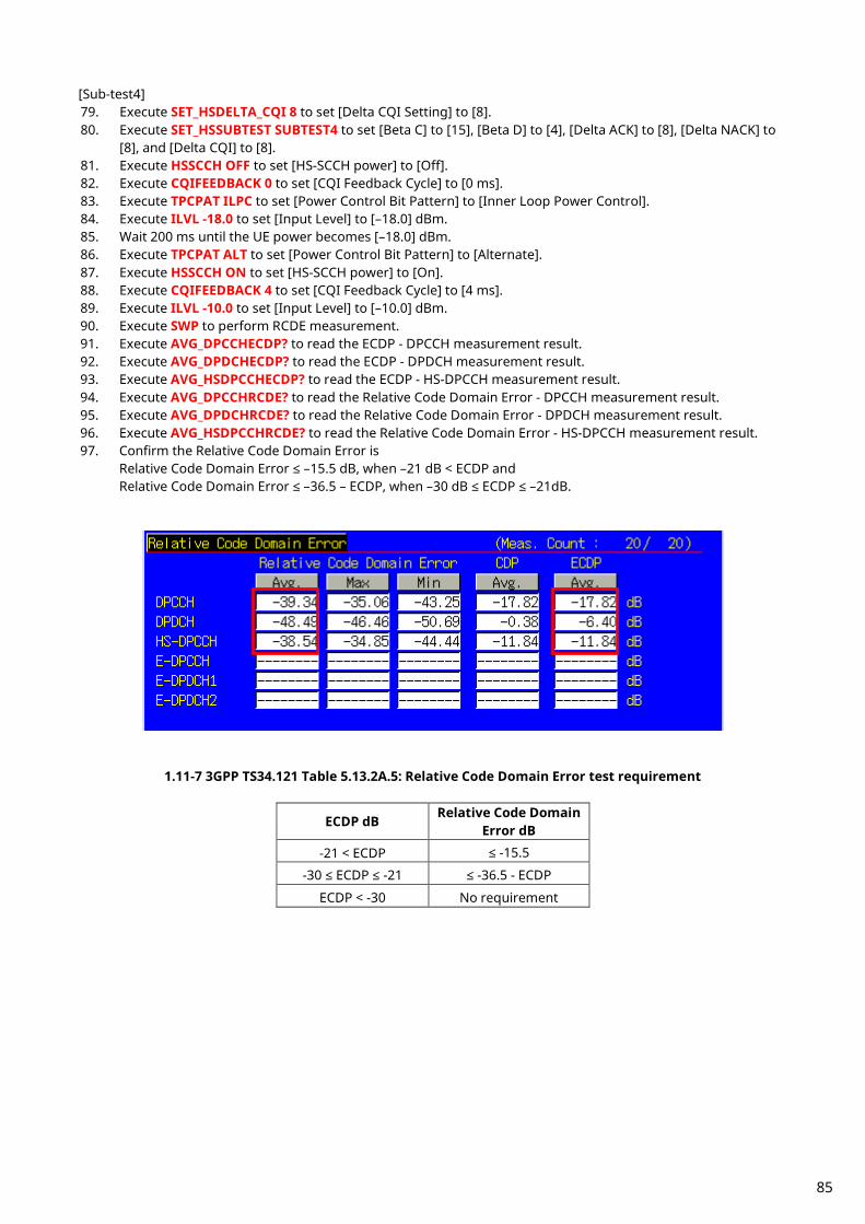
[Sub-test4] 79. Execute SET_HSDELTA_CQI 8 to set [Delta CQI Setting] to [8]. 80. Execute SET_HSSUBTEST SUBTEST4 to set [Beta C] to [15], [Beta D] to [4], [Delta ACK] to [8], [Delta NACK] to
[8], and [Delta CQI] to [8]. 81. Execute HSSCCH OFF to set [HS-SCCH power] to [Off]. 82. Execute CQIFEEDBACK 0 to set [CQI Feedback Cycle] to [0 ms]. 83. Execute TPCPAT ILPC to set [Power Control Bit Pattern] to [Inner Loop Power Control]. 84. Execute ILVL -18.0 to set [Input Level] to [–18.0] dBm. 85. Wait 200 ms until the UE power becomes [–18.0] dBm. 86. Execute TPCPAT ALT to set [Power Control Bit Pattern] to [Alternate]. 87. Execute HSSCCH ON to set [HS-SCCH power] to [On]. 88. Execute CQIFEEDBACK 4 to set [CQI Feedback Cycle] to [4 ms]. 89. Execute ILVL -10.0 to set [Input Level] to [–10.0] dBm. 90. Execute SWP to perform RCDE measurement. 91. Execute AVG_DPCCHECDP? to read the ECDP - DPCCH measurement result. 92. Execute AVG_DPDCHECDP? to read the ECDP - DPDCH measurement result. 93. Execute AVG_HSDPCCHECDP? to read the ECDP - HS-DPCCH measurement result. 94. Execute AVG_DPCCHRCDE? to read the Relative Code Domain Error - DPCCH measurement result. 95. Execute AVG_DPDCHRCDE? to read the Relative Code Domain Error - DPDCH measurement result. 96. Execute AVG_HSDPCCHRCDE? to read the Relative Code Domain Error - HS-DPCCH measurement result. 97. Confirm the Relative Code Domain Error is
Relative Code Domain Error ≤ –15.5 dB, when –21 dB < ECDP and Relative Code Domain Error ≤ –36.5 – ECDP, when –30 dB ≤ ECDP ≤ –21dB.
1.11-7 3GPP TS34.121 Table 5.13.2A.5: Relative Code Domain Error test requirement
ECDP dB Relative Code Domain Error dB
-21 < ECDP ≤ -15.5
-30 ≤ ECDP ≤ -21 ≤ -36.5 - ECDP
ECDP < -30 No requirement
85

1.11.14. 6.3A Maximum Input Level for HS-PDSCH Reception (16QAM)
1. Execute ULGAINPAR 8,15,8,8,8 to set [Beta C] to [8], [Beta D] to [15], [Delta ACK] to [8], [Delta NACK] to [8], [Delta CQI] to [8].
2. Execute TPCALGO 2 to set [Power Control Algorithm] to [Algorithm 2]. 3. Execute CHAN 9750 to set to M channel. (in case of Band I) 4. Connect with Fixed Reference Channel H-Set1(16QAM). 5. Execute TPCPAT ILPC to set [Power Control Bit Pattern] to [Inner Loop Power Control]. 6. Execute ILVL 20.0 to set [Input Level] to [+20.0] dBm. 7. Wait 100 ms until UE power becomes [+20.0] dBm. 8. Execute TPCPAT ALT to set [Power Control Bit Pattern] to [Alternate]. 9. Execute OLVL -25.7 to set [Output Level] to [–25.7] dBm.
10. Execute DDPCHPWR -13.0 to set [DPCH_Ec/Ior] to [–13.0] dB. 11. Execute HSSCCHPWR -13.0 to set [HS-SCCH_Ec/Ior] to [–13.0] dB. 12. Execute HSPDSCHPWR -3.0 to set [HS-PDSCH_Ec/Ior] to [–3.0] dB. 13. Execute TPUT_MEAS On to set [HSDPA Throughput] measurement to [On]. 14. Execute TPUT_SAMPLE 1000 to set [Number of Sample] of HSDPA Throughput to [1000] Block. 15. Execute SWP to perform HSDPA Throughput measurement. 16. Execute TPUTPASS? to read the HSDPA Throughput measurement result.
86
1.12. HSUPA Measurement
1.12.1. E-DCH RF Test Location Registration Location registration with E-DCH RF Test is required when connecting using HSUPA.
1. Execute PRESET_3GPP to preset parameter for 3GPP. 2. Execute CHCODING EDCHTEST to set [Channel Coding] to [E-DCH RF Test]. 3. Execute HSUSET TTI10_QPSK to set [HSUPA Set of Parameters] to [TTI 10ms(QPSK)]. 4. Execute INTEGRITY On to set [Integrity Protection] to [On]. 5. Turn on the UE. 6. Execute CALLSTAT? and wait until the response becomes 2 (= Idle(Regist)).
1.12.2. E-DCH RF Test Connection The process for performing E-DCH RF Test connection after location registration is shown below. (See 1.12.1 E-DCH RF Test Location Registration.)
1. Execute CALLSA to connect with E-DCH RF Test. 2. Execute CALLSTAT? and wait until the response becomes 7 (= Test Loop Mode).
1.12.3. E-DCH RF Test Disconnection
1. Execute CALLSO to disconnect from E-DCH RF Test. 2. Execute CALLSTAT? and wait until the response becomes 2 (= Idle(Regist)).
1.12.4. Channel Change at Handover Usually, measurement is performed at three frequency points (L, M, H). In this case, the Channel can be switched quickly without reconnection by switching it at handover with a higher output level. When a GPIB command is sent during handover, it waits until handover ends.
1. Execute TRX measurement with M channel. 2. Execute CHAN 9613 to handover to L channel. 3. Execute TRX measurement. 4. Execute CHAN 9887 to handover to H channel. 5. Execute TRX measurement.
87

1.12.5. Change of βc and βd by Transport Channel Reconfiguration When performing HSUPA measurement, gain parameters such as βc, βd must be changed according to the measurement conditions. In this case, measurement can be performed without reconnection by changing parameters during call processing at Transport Channel Reconfiguration. In addition, when a GPIB command is sent during Transport Channel Reconfiguration, it waits until Transport Channel Reconfiguration ends.
1. Connect with E-DCH RF Test. 2. Execute ALLREFETFCI 5,11,4,67,18,71,23,75,26,81,27 to set [Number of E-TFCIs] to [5], [Reference E-TFCI] to
[11,67,71,75,81], [Reference E-TFCI PO] to [4,18,23,26,27]. 3. Execute ULGAINPAR 12,15,8,8,8,6 to set [βc] to 12, [βd] to [15], [Delta ACK] to [8], [Delta NACK] to [8], [Delta
CQI] to [8], [Delta E-DPCCH] to [6]. 4. Perform Tx measurement. 5. Execute ALLREFETFCI 2,11,4,92,18 to set [Number of E-TFCIs] to [2], [Reference E-TFCI] to [11,92], [Reference
E-TFCI PO] to [4,18]. 6. Execute ULGAINPAR 6,15,8,8,8,8 to set [βc] to [6], [βd] to [15], [Delta ACK] to [8], [Delta NACK] to [8], [Delta
CQI] to [8], [Delta E-DPCCH] to [8]. 7. Perform Tx measurement.
1.12.6. Measurement Item Selection The MT8820/15B is preset for W-CDMA measurement. Since HSUPA Throughput measurement items are preset to off, turn on these items to measure (TPUTU_MEAS ON) Although other measurement items are preset to on, turn off unnecessary items, such as BER measurement and
BLER measurement, to cut the measurement time (BER_MEAS OFF, BLER_MEAS OFF).
88

1.12.7. 5.2B Maximum Output Power with HS-DPCCH and E-DCH
1. Execute DDPCHTOFS 6 to set [DPCH Timing Offset] to [6]. 2. Execute MAXULPWR 21 to set [Maximum Allowed UL TX Power] to [21.0] dBm. 3. Execute CHCODING EDCHTEST to set [Channel Coding] to [E-DCH RF Test]. 4. Execute HSUSET TTI10_QPSK to set [HSUPA Set of Parameters] to [TTI 10ms(QPSK)]. 5. Execute SET_PWRPAT HSMAXPWR to set [CQI Feedback Cycle] to [4 ms], [Ack-Nack Repetition Factor] to [3],
[CQI Repetition Factor] to [2], and [TPC Algorithm] to [2]. 6. Connect with Fixed Reference Channel H-Set1 (QPSK). 7. Execute OLVL -86.0 to set [Output Level] to [-86.0dBm]. 8. Execute PWR_MEAS ON to set [Power measurement] to [On]. 9. Execute PWR_AVG 20 to set [Average Count] of Power measurement to [20] times.
10. Execute TPUTU_MEAS ON to set [HSUPA Throughput] measurement to [On]. 11. Execute TPUTU_SAMPLE 15 to set [HSUPA Throughput - Number of Sample] to [15]. 12. Execute EHICHPAT ACK to set [E-HICH Pattern] to [ACK]. [Subtest1] 13. Execute SET_HSDELTA_CQI 8 to set [Delta CQI Setting] to [8]. 14. Execute SET_HSSUBTEST SUBTEST1 to set [Absolute Grant Value] to [20], [Number of E-TFCIs] to [5],
[Reference E-TFCI] to [11,67,71,75,81], [Reference E-TFCI PO] to [4,18,23,26,27], [Beta C] to [10], [Beta D] to [15], [Delta ACK] to [8], [Delta NACK] to [8], [Delta CQI] to [8], [Delta E-DPCCH] to [6].
15. Execute TPCPAT ILPC to set [Power Control Bit Pattern] to [Inner Loop Power Control]. 16. Execute ILVL 16.0 to set [Input Level] to [+16.0] dBm. 17. Wait 150 ms until the UE power becomes 16.0 dBm. 18. Execute TPCPAT ALT to set [Power Control Bit Pattern] to [Alternate]. 19. Execute ILVL 26.0 to set [Input Level] to [+26.0] dBm. 20. Execute SWP to perform HSUPA Throughput measurement and confirm the E-TFCI measurement result is
75. 21. Execute TPC_CMD_UP to raise [TxPower] only 1 dB and wait 150 ms. 22. Execute SWP to perform HSUPA Throughput measurement.
23. Execute AVG_ETFCI? to read the E-TFCI measurement result, and confirm it is 75. 24. Repeat procedures 21 to 23 until the E-TFCI measurement result is not 75. Execute measurement by
reducing [Input Level] only 1 dB, and confirm the E-TFCI measurement result is 75 again. 25. Execute TPC_CMD_DOWN to reduce [TxPower] only 1 dB and wait 150 ms. 26. Execute SWP to perform HSUPA Throughput measurement, and confirm the E-TFCI measurement result is 75.
(Repeat procedures 25 and 26 if the E-TFCI measurement result is not 75.) 27. Execute AVG_POWER? to read the Power measurement result. 28. Confirm the measurement result is +24 dBm (Tolerance +1.7/–6.7 dB).
TX Power means Mean power (5 MHz band), and Filtered Power means RRC filtered mean power.
89

90

[Subtest2] 29. Execute SET_HSDELTA_CQI 8 to set [Delta CQI Setting] to [8]. 30. Execute SET_HSSUBTEST SUBTEST2 to set [Absolute Grant Value] to [12], [Number of E-TFCIs] to [5],
[Reference E-TFCI] to [11,67,71,75,81], [Reference E-TFCI PO] to [4,18,23,26,27], [Beta C] to [6], [Beta D] to [15], [Delta ACK] to [8], [Delta NACK] to [8], [Delta CQI] to [8], [Delta E-DPCCH] to [8].
31. Execute TPCPAT ILPC to set [Power Control Bit Pattern] to [Inner Loop Power Control]. 32. Execute ILVL 14.0 to set [Input Level] to [+14.0] dBm. 33. Wait 150 ms until the UE power becomes 14.0 dBm. 34. Execute TPCPAT ALT to set [Power Control Bit Pattern] to [Alternate]. 35. Execute ILVL 26.0 to set [Input Level] to [+26.0] dBm. 36. Execute SWP to perform HSUPA Throughput measurement, and confirm the E-TFCI measurement result is
67. 37. Execute TPC_CMD_UP to raise [TxPower] only 1 dB and wait 150 ms. 38. Execute SWP to perform HSUPA Throughput measurement. 39. Execute AVG_ETFCI? to read E-TFCI measurement result, and confirm it is 67. 40. Repeat procedures 37 to 39 until the E-TFCI measurement result is not 67. 41. Execute TPC_CMD_DOWN to reduce [TxPower] only 1 dB and wait 150 ms. 42. Execute SWP to perform HSUPA Throughput measurement, and confirm the E-TFCI measurement result is
67. (Repeat procedures 41 and 42 if the E-TFCI measurement result is not 67.)
43. Execute AVG_POWER? to read the Power measurement result. 44. Confirm the measurement result is +22 dBm (Tolerance +3.7/–5.2 dB). [Subtest3] 45. Execute SET_HSDELTA_CQI 8 to set [Delta CQI Setting] to [8]. 46. Execute SET_HSSUBTEST SUBTEST3 to set [Absolute Grant Value] to [15], [Number of E-TFCIs] to [2],
[Reference E-TFCI] to [11,92], [Reference E-TFCI PO] to [4,18], [Beta C] to [15], [Beta D] to [9], [Delta ACK] to [8], [Delta NACK] to [8], [Delta CQI] to [8], [Delta E-DPCCH] to [8].
47. Execute TPCPAT ILPC to set [Power Control Bit Pattern] to [Inner Loop Power Control]. 48. Execute ILVL 15.0 to set [Input Level] to [+15.0] dBm. 49. Wait 100 ms until the UE power becomes 15.0 dBm. 50. Execute TPCPAT ALT to set [Power Control Bit Pattern] to [Alternate]. 51. Execute ILVL 26.0 to set [Input Level] to [+26.0] dBm. 52. Execute SWP to perform HSUPA Throughput measurement, and confirm the E-TFCI measurement result is
92. 53. Execute TPC_CMD_UP to raise [TxPower] only 1 dB and wait 150 ms. 54. Execute SWP to perform HSUPA Throughput measurement. 55. Execute AVG_ETFCI? to read the E-TFCI measurement result, and confirm it is 92. 56. Repeat procedures 53 to 55 until the E-TFCI measurement result is not 92. 57. Execute TPC_CMD_DOWN to reduce [TxPower] only 1 dB and wait 150 ms. 58. Execute SWP to perform HSUPA Throughput measurement, and confirm the E-TFCI measurement result is
92. (Repeat procedures 57 and 58 if the E-TFCI measurement result is not 92.)
59. Execute AVG_POWER? to read the Power measurement result. 60. Confirm the measurement result is +23 dBm (Tolerance +2.7/–5.2 dB).
91

[Subtest4] 61. Execute SET_HSDELTA_CQI 8 to set [Delta CQI Setting] to [8]. 62. Execute SET_HSSUBTEST SUBTEST4 to set [Absolute Grant Value] to [17], [Number of E-TFCIs] to [5],
[Reference E-TFCI] to [11,67,71,75,81], [Reference E-TFCI PO] to [4,18,23,26,27], [Beta C] to [2], [Beta D] to [15], [Delta ACK] to [8], [Delta NACK] to [8], [Delta CQI] to [8], [Delta E-DPCCH] to [5].
63. Execute TPCPAT ILPC to set [Power Control Bit Pattern] to [Inner Loop Power Control]. 64. Execute ILVL 14.0 to set [Input Level] to [+14.0] dBm. 65. Wait 100 ms until the UE power becomes 14.0 dBm. 66. Execute TPCPAT ALT to set [Power Control Bit Pattern] to [Alternate]. 67. Execute ILVL 26.0 to set [Input Level] to [+26.0] dBm. 68. Execute SWP to perform HSUPA Throughput measurement, and confirm the E-TFCI measurement result is
71. 69. Execute TPC_CMD_UP to raise [TxPower] only 1 dB and wait 150 ms. 70. Execute SWP to perform HSUPA Throughput measurement. 71. Execute AVG_ETFCI? to read the E-TFCI measurement result, and confirm it is 71. 72. Repeat procedures 69 to 71 until the E-TFCI measurement result is not 71. 73. Execute TPC_CMD_DOWN to reduce [TxPower] only 1 dB and wait 150 ms. 74. Execute SWP to perform HSUPA Throughput measurement, and confirm the E-TFCI measurement result is
71. (Repeat procedures 73 and 74 if the E-TFCI measurement result is not 71.)
75. Execute AVG_POWER? to read Power measurement result. 76. Confirm the measurement result is +22 dBm (Tolerance +3.7/–5.2 dB). [Subtest5 –before v8.7.0] 77. Execute SUBTEST5_VER OLD to set [Sub-test5 Version] to [Old]. 78. Execute SET_HSDELTA_CQI 8 to set [Delta CQI Setting] to [8]. 79. Execute SET_HSSUBTEST SUBTEST5 to set [Absolute Grant Value] to [21], [Number of E-TFCIs] to [5],
[Reference E-TFCI] to [11,67,71,75,81], [Reference E-TFCI PO] to [4,18,23,26,27], [Beta C] to [14], [Beta D] to [15], [Delta ACK] to [8], [Delta NACK] to [8], [Delta CQI] to [8], [Delta E-DPCCH] to [7].
80. Execute TPCPAT ILPC to set [Power Control Bit Pattern] to [Inner Loop Power Control]. 81. Execute ILVL 16.0 to set [Input Level] to [+16.0] dBm. 82. Wait 100 ms until the UE power becomes 16.0 dBm. 83. Execute TPCPAT ALT to set [Power Control Bit Pattern] to [Alternate]. 84. Execute ILVL 26.0 to set [Input Level] to [+26.0] dBm. 85. Execute SWP to perform HSUPA Throughput measurement, and confirm the E-TFCI measurement result is
81. 86. Execute TPC_CMD_UP to raise [TxPower] only 1 dB and wait 150 ms. 87. Execute SWP to perform HSUPA Throughput measurement. 88. Execute AVG_ETFCI? to read the E-TFCI measurement result, and confirm it is 81. 89. Repeat procedures 86 to 88 until the E-TFCI measurement result is not 81. 90. Execute TPC_CMD_DOWN to reduce [TxPower] only 1 dB and wait 150 ms. 91. Execute SWP to perform HSUPA Throughput measurement, and confirm the E-TFCI measurement result is
81. 92. Repeat procedures 90 and 91 if the E-TFCI measurement result is not 81.) 93. Execute AVG_POWER? to read the Power measurement result. 94. Confirm the measurement result is +24 dBm (Tolerance +1.7/–6.7 dB).
92
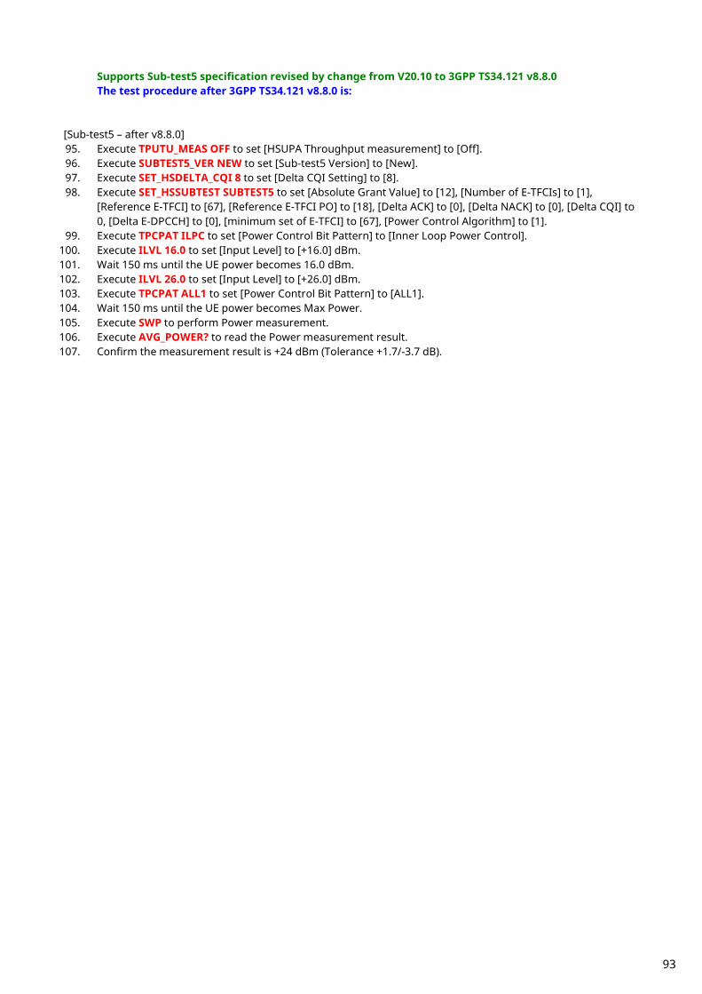
Supports Sub-test5 specification revised by change from V20.10 to 3GPP TS34.121 v8.8.0 The test procedure after 3GPP TS34.121 v8.8.0 is:
[Sub-test5 – after v8.8.0] 95. Execute TPUTU_MEAS OFF to set [HSUPA Throughput measurement] to [Off]. 96. Execute SUBTEST5_VER NEW to set [Sub-test5 Version] to [New]. 97. Execute SET_HSDELTA_CQI 8 to set [Delta CQI Setting] to [8]. 98. Execute SET_HSSUBTEST SUBTEST5 to set [Absolute Grant Value] to [12], [Number of E-TFCIs] to [1],
[Reference E-TFCI] to [67], [Reference E-TFCI PO] to [18], [Delta ACK] to [0], [Delta NACK] to [0], [Delta CQI] to 0, [Delta E-DPCCH] to [0], [minimum set of E-TFCI] to [67], [Power Control Algorithm] to [1].
99. Execute TPCPAT ILPC to set [Power Control Bit Pattern] to [Inner Loop Power Control]. 100. Execute ILVL 16.0 to set [Input Level] to [+16.0] dBm. 101. Wait 150 ms until the UE power becomes 16.0 dBm. 102. Execute ILVL 26.0 to set [Input Level] to [+26.0] dBm. 103. Execute TPCPAT ALL1 to set [Power Control Bit Pattern] to [ALL1]. 104. Wait 150 ms until the UE power becomes Max Power. 105. Execute SWP to perform Power measurement. 106. Execute AVG_POWER? to read the Power measurement result. 107. Confirm the measurement result is +24 dBm (Tolerance +1.7/-3.7 dB).
93
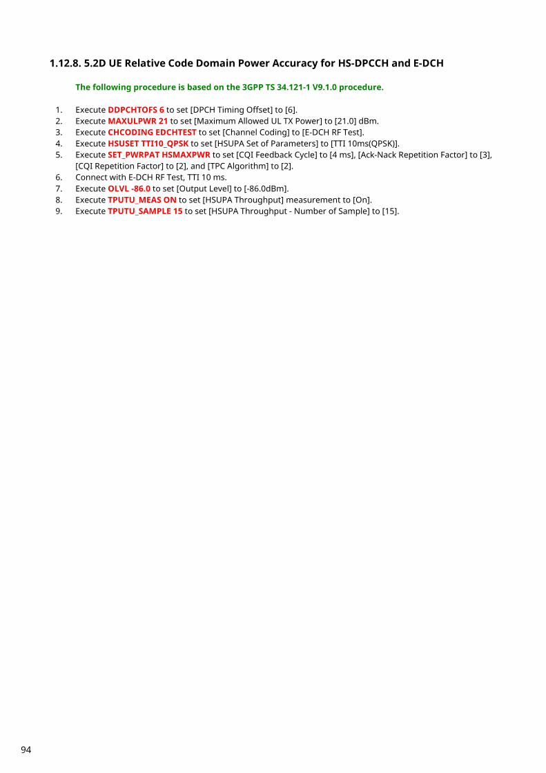
1.12.8. 5.2D UE Relative Code Domain Power Accuracy for HS-DPCCH and E-DCH
The following procedure is based on the 3GPP TS 34.121-1 V9.1.0 procedure.
1. Execute DDPCHTOFS 6 to set [DPCH Timing Offset] to [6]. 2. Execute MAXULPWR 21 to set [Maximum Allowed UL TX Power] to [21.0] dBm. 3. Execute CHCODING EDCHTEST to set [Channel Coding] to [E-DCH RF Test]. 4. Execute HSUSET TTI10_QPSK to set [HSUPA Set of Parameters] to [TTI 10ms(QPSK)]. 5. Execute SET_PWRPAT HSMAXPWR to set [CQI Feedback Cycle] to [4 ms], [Ack-Nack Repetition Factor] to [3],
[CQI Repetition Factor] to [2], and [TPC Algorithm] to [2]. 6. Connect with E-DCH RF Test, TTI 10 ms. 7. Execute OLVL -86.0 to set [Output Level] to [-86.0dBm]. 8. Execute TPUTU_MEAS ON to set [HSUPA Throughput] measurement to [On]. 9. Execute TPUTU_SAMPLE 15 to set [HSUPA Throughput - Number of Sample] to [15].
94
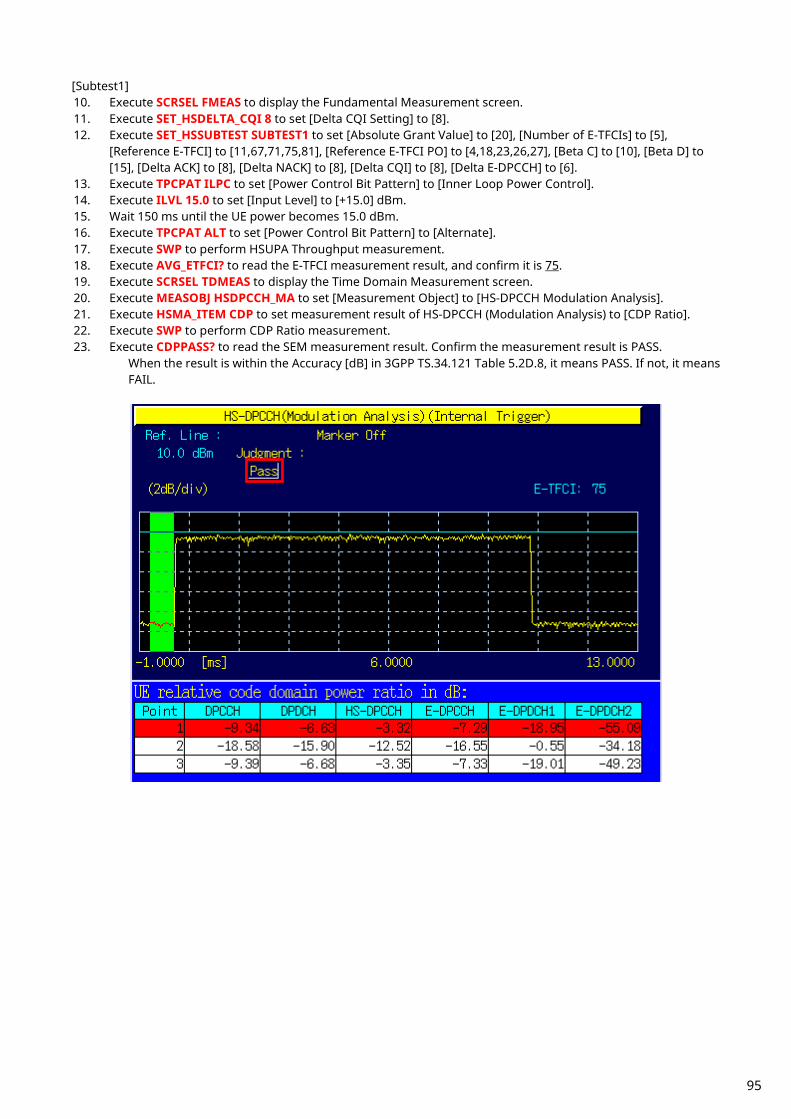
[Subtest1] 10. Execute SCRSEL FMEAS to display the Fundamental Measurement screen. 11. Execute SET_HSDELTA_CQI 8 to set [Delta CQI Setting] to [8]. 12. Execute SET_HSSUBTEST SUBTEST1 to set [Absolute Grant Value] to [20], [Number of E-TFCIs] to [5],
[Reference E-TFCI] to [11,67,71,75,81], [Reference E-TFCI PO] to [4,18,23,26,27], [Beta C] to [10], [Beta D] to [15], [Delta ACK] to [8], [Delta NACK] to [8], [Delta CQI] to [8], [Delta E-DPCCH] to [6].
13. Execute TPCPAT ILPC to set [Power Control Bit Pattern] to [Inner Loop Power Control]. 14. Execute ILVL 15.0 to set [Input Level] to [+15.0] dBm. 15. Wait 150 ms until the UE power becomes 15.0 dBm. 16. Execute TPCPAT ALT to set [Power Control Bit Pattern] to [Alternate]. 17. Execute SWP to perform HSUPA Throughput measurement. 18. Execute AVG_ETFCI? to read the E-TFCI measurement result, and confirm it is 75. 19. Execute SCRSEL TDMEAS to display the Time Domain Measurement screen. 20. Execute MEASOBJ HSDPCCH_MA to set [Measurement Object] to [HS-DPCCH Modulation Analysis]. 21. Execute HSMA_ITEM CDP to set measurement result of HS-DPCCH (Modulation Analysis) to [CDP Ratio]. 22. Execute SWP to perform CDP Ratio measurement. 23. Execute CDPPASS? to read the SEM measurement result. Confirm the measurement result is PASS.
When the result is within the Accuracy [dB] in 3GPP TS.34.121 Table 5.2D.8, it means PASS. If not, it means FAIL.
95

[Subtest2] 24. Execute SCRSEL FMEAS to display the Fundamental Measurement screen. 25. Execute SET_HSDELTA_CQI 8 to set [Delta CQI Setting] to [8]. 26. Execute SET_HSSUBTEST SUBTEST2 to set [Absolute Grant Value] to [12], [Number of E-TFCIs] to [5],
[Reference E-TFCI] to [11,67,71,75,81], [Reference E-TFCI PO] to [4,18,23,26,27], [Beta C] to [6], [Beta D] to [15], [Delta ACK] to [8], [Delta NACK] to [8], [Delta CQI] to [8], [Delta E-DPCCH] to [8].
27. Execute TPCPAT ILPC to set [Power Control Bit Pattern] to [Inner Loop Power Control]. 28. Execute ILVL 15.0 to set [Input Level] to [+15.0] dBm. 29. Wait 150 ms until the UE power becomes 15.0 dBm. 30. Execute TPCPAT ALT to set [Power Control Bit Pattern] to [Alternate]. 31. Execute SWP to perform HSUPA Throughput measurement. 32. Execute AVG_ETFCI? to read the E-TFCI measurement result, and confirm it is 75. 33. Execute SCRSEL TDMEAS to display the Time Domain Measurement screen. 34. Execute MEASOBJ HSDPCCH_MA to set [Measurement Object] to [HS-DPCCH Modulation Analysis]. 35. Execute HSMA_ITEM CDP to set measurement result of HS-DPCCH (Modulation Analysis) to [CDP Ratio]. 36. Execute SWP to perform CDP Ratio measurement. 37. Execute CDPPASS? to read the SEM measurement result. Confirm the measurement result is PASS.
When the result is within the Accuracy [dB] in 3GPP TS.34.121 Table 5.2D.8, it means PASS. If not, it means FAIL.
96
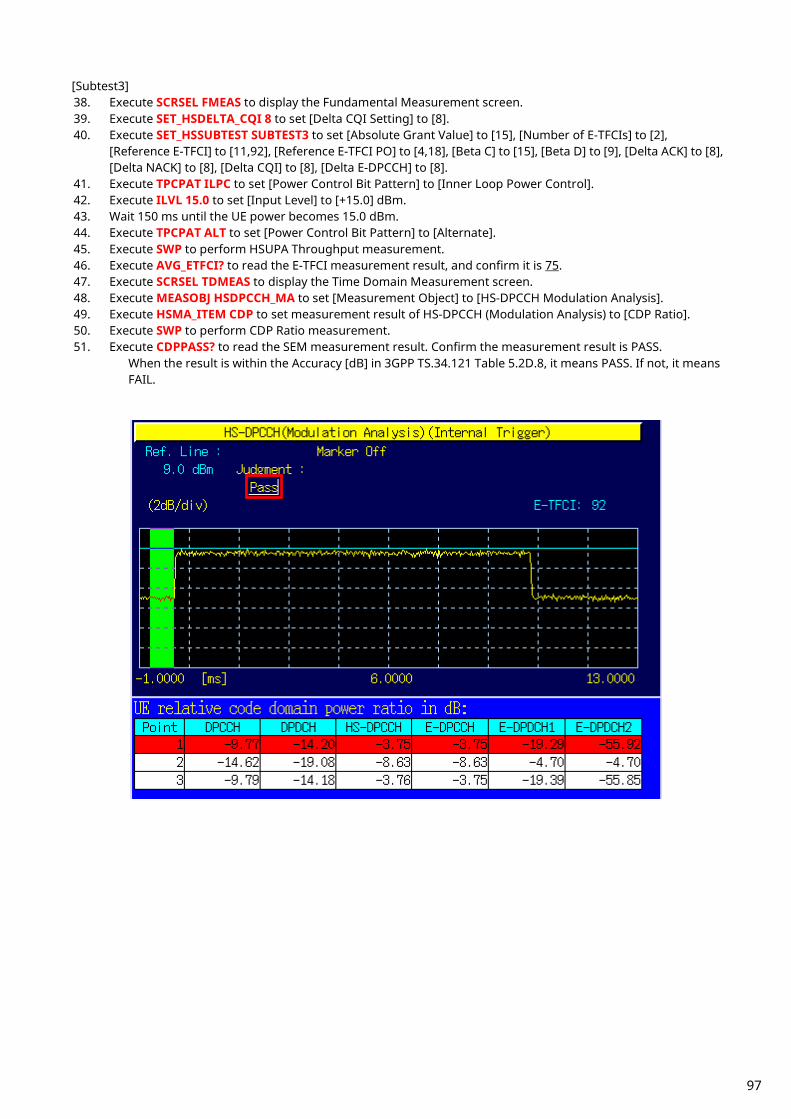
[Subtest3] 38. Execute SCRSEL FMEAS to display the Fundamental Measurement screen. 39. Execute SET_HSDELTA_CQI 8 to set [Delta CQI Setting] to [8]. 40. Execute SET_HSSUBTEST SUBTEST3 to set [Absolute Grant Value] to [15], [Number of E-TFCIs] to [2],
[Reference E-TFCI] to [11,92], [Reference E-TFCI PO] to [4,18], [Beta C] to [15], [Beta D] to [9], [Delta ACK] to [8], [Delta NACK] to [8], [Delta CQI] to [8], [Delta E-DPCCH] to [8].
41. Execute TPCPAT ILPC to set [Power Control Bit Pattern] to [Inner Loop Power Control]. 42. Execute ILVL 15.0 to set [Input Level] to [+15.0] dBm. 43. Wait 150 ms until the UE power becomes 15.0 dBm. 44. Execute TPCPAT ALT to set [Power Control Bit Pattern] to [Alternate]. 45. Execute SWP to perform HSUPA Throughput measurement. 46. Execute AVG_ETFCI? to read the E-TFCI measurement result, and confirm it is 75. 47. Execute SCRSEL TDMEAS to display the Time Domain Measurement screen. 48. Execute MEASOBJ HSDPCCH_MA to set [Measurement Object] to [HS-DPCCH Modulation Analysis]. 49. Execute HSMA_ITEM CDP to set measurement result of HS-DPCCH (Modulation Analysis) to [CDP Ratio]. 50. Execute SWP to perform CDP Ratio measurement. 51. Execute CDPPASS? to read the SEM measurement result. Confirm the measurement result is PASS.
When the result is within the Accuracy [dB] in 3GPP TS.34.121 Table 5.2D.8, it means PASS. If not, it means FAIL.
97

[Subtest4] 52. Execute SCRSEL FMEAS to display the Fundamental Measurement screen. 53. Execute SET_HSDELTA_CQI 8 to set [Delta CQI Setting] to [8]. 54. Execute SET_HSSUBTEST SUBTEST4 to set [Absolute Grant Value] to [17], [Number of E-TFCIs] to [5],
[Reference E-TFCI] to [11,67,71,75,81], [Reference E-TFCI PO] to [4,18,23,26,27], [Beta C] to [2], [Beta D] to [15], [Delta ACK] to [8], [Delta NACK] to [8], [Delta CQI] to [8], [Delta E-DPCCH] to [5].
55. Execute TPCPAT ILPC to set [Power Control Bit Pattern] to [Inner Loop Power Control]. 56. Execute ILVL 15.0 to set [Input Level] to [+15.0] dBm. 57. Wait 150 ms until the UE power becomes 15.0 dBm. 58. Execute TPCPAT ALT to set [Power Control Bit Pattern] to [Alternate]. 59. Execute SWP to perform HSUPA Throughput measurement. 60. Execute AVG_ETFCI? to read the E-TFCI measurement result, and confirm it is 75. 61. Execute SCRSEL TDMEAS to display the Time Domain Measurement screen. 62. Execute MEASOBJ HSDPCCH_MA to set [Measurement Object] to [HS-DPCCH Modulation Analysis]. 63. Execute HSMA_ITEM CDP to set measurement result of HS-DPCCH (Modulation Analysis) to [CDP Ratio]. 64. Execute SWP to perform CDP Ratio measurement. 65. Execute CDPPASS? to read the SEM measurement result. Confirm the measurement result is PASS.
When the result is within the Accuracy [dB] in 3GPP TS.34.121 Table 5.2D.8, it means PASS. If not, it means FAIL.
98
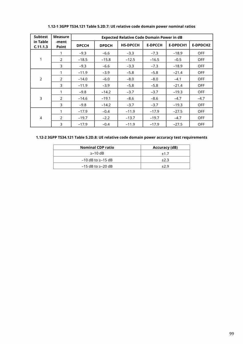
1.12-1 3GPP TS34.121 Table 5.2D.7: UE relative code domain power nominal ratios
Subtest in Table C.11.1.3
Measure-ment Point
Expected Relative Code Domain Power in dB
DPCCH DPDCH HS-DPCCH E-DPCCH E-DPDCH1 E-DPDCH2
1 1 –9.3 –6.6 –3.3 –7.3 –18.9 OFF
2 –18.5 –15.8 –12.5 –16.5 –0.5 OFF
3 –9.3 –6.6 –3.3 –7.3 –18.9 OFF
2
1 –11.9 –3.9 –5.8 –5.8 –21.4 OFF
2 –14.0 –6.0 –8.0 –8.0 –4.1 OFF
3 –11.9 –3.9 –5.8 –5.8 –21.4 OFF
3
1 –9.8 –14.2 –3.7 –3.7 –19.3 OFF
2 –14.6 –19.1 –8.6 –8.6 –4.7 –4.7
3 –9.8 –14.2 –3.7 –3.7 –19.3 OFF
4
1 –17.9 –0.4 –11.9 –17.9 –27.5 OFF
2 –19.7 –2.2 –13.7 –19.7 –4.7 OFF
3 –17.9 –0.4 –11.9 –17.9 –27.5 OFF
1.12-2 3GPP TS34.121 Table 5.2D.8: UE relative code domain power accuracy test requirements
Nominal CDP ratio Accuracy (dB) ≥–10 dB ±1.7
–10 dB to ≥–15 dB ±2.3
–15 dB to ≥–20 dB ±2.9
99
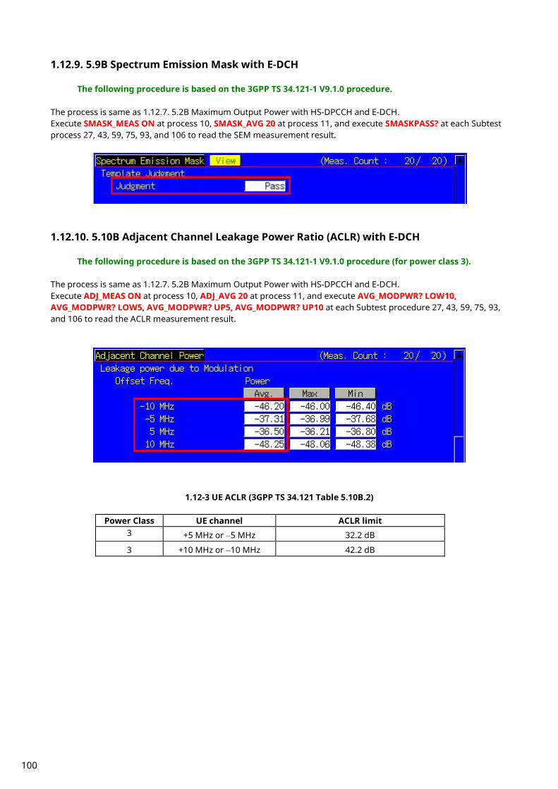
1.12.9. 5.9B Spectrum Emission Mask with E-DCH
The following procedure is based on the 3GPP TS 34.121-1 V9.1.0 procedure. The process is same as 1.12.7. 5.2B Maximum Output Power with HS-DPCCH and E-DCH. Execute SMASK_MEAS ON at process 10, SMASK_AVG 20 at process 11, and execute SMASKPASS? at each Subtest process 27, 43, 59, 75, 93, and 106 to read the SEM measurement result.
1.12.10. 5.10B Adjacent Channel Leakage Power Ratio (ACLR) with E-DCH
The following procedure is based on the 3GPP TS 34.121-1 V9.1.0 procedure (for power class 3). The process is same as 1.12.7. 5.2B Maximum Output Power with HS-DPCCH and E-DCH. Execute ADJ_MEAS ON at process 10, ADJ_AVG 20 at process 11, and execute AVG_MODPWR? LOW10, AVG_MODPWR? LOW5, AVG_MODPWR? UP5, AVG_MODPWR? UP10 at each Subtest procedure 27, 43, 59, 75, 93, and 106 to read the ACLR measurement result.
1.12-3 UE ACLR (3GPP TS 34.121 Table 5.10B.2)
Power Class UE channel ACLR limit 3 +5 MHz or −5 MHz 32.2 dB
3 +10 MHz or −10 MHz 42.2 dB
100

1.12.11. 5.13.2B Relative Code Domain Error with HS-DPCCH and E-DCH
1. Execute DDPCHTOFS 6 to set [DPCH Timing Offset] to [6]. 2. Execute MAXULPWR 21 to set [Maximum Allowed UL TX Power] to [21.0] dBm. 3. Execute CHCODING EDCHTEST to set [Channel Coding] to [E-DCH RF Test]. 4. Execute HSUSET TTI10_QPSK to set [HSUPA Set of Parameters] to [TTI 10ms(QPSK)]. 5. Execute SET_PWRPAT HSMAXPWR to set [CQI Feedback Cycle] to [4 ms], [Ack-Nack Repetition Factor] to [3],
[CQI Repetition Factor] to [2], and [TPC Algorithm] to [2]. 6. Connect with E-DCH RF Test, TTI 10ms. 7. Execute OLVL -86.0 to set [Output Level] to [-86.0dBm]. 8. Execute DTCHPAT PN9 to set [DTCH Data Pattern] to [PN9]. 9. Execute RCDE_MEAS ON to set [RCDE measurement] to [On].
10. Execute RCDE_AVG 20 to set [Average Count] of RCDE measurement to [20] times. 11. Execute TPUTU_MEAS ON to set [HSUPA Throughput measurement] to [On]. 12. Execute TPUTU_SAMPLE 15 to set [HSUPA Throughput - Number of Sample] to [15].
101
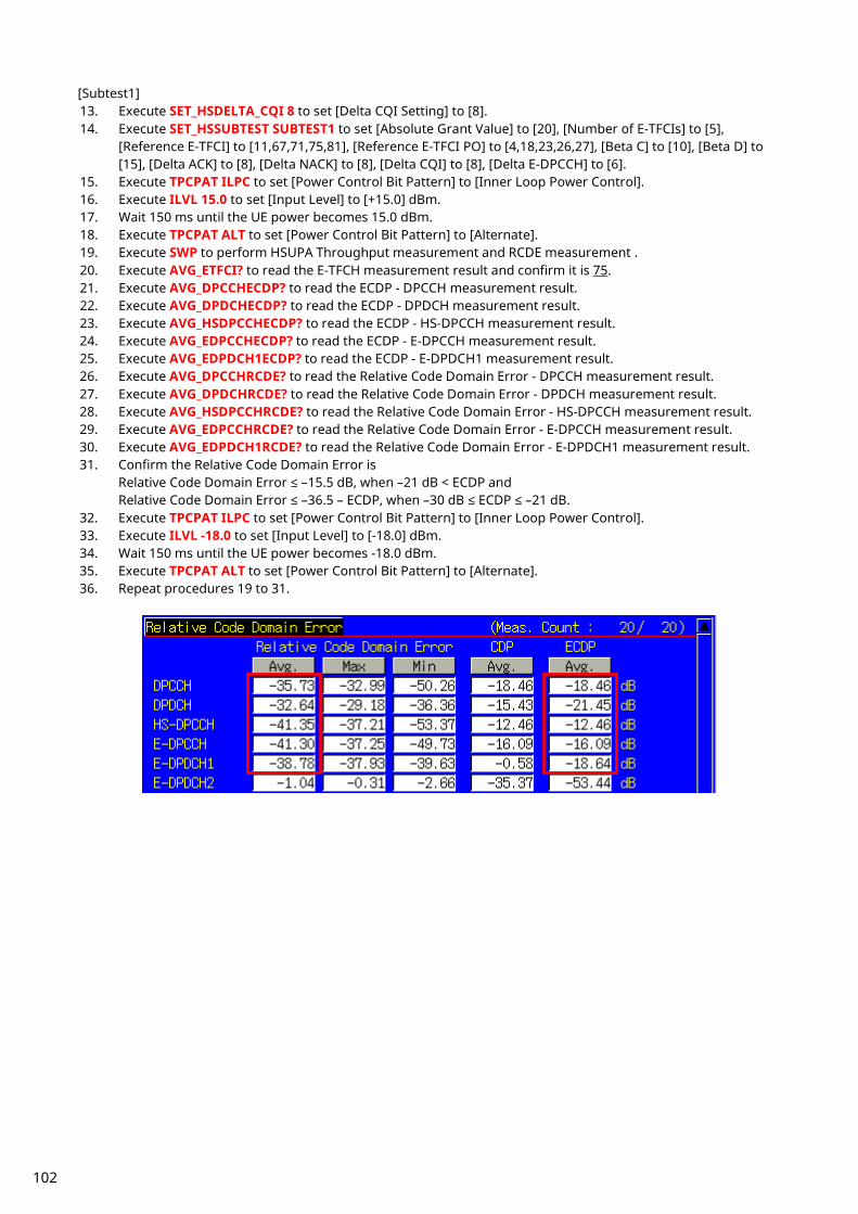
[Subtest1] 13. Execute SET_HSDELTA_CQI 8 to set [Delta CQI Setting] to [8]. 14. Execute SET_HSSUBTEST SUBTEST1 to set [Absolute Grant Value] to [20], [Number of E-TFCIs] to [5],
[Reference E-TFCI] to [11,67,71,75,81], [Reference E-TFCI PO] to [4,18,23,26,27], [Beta C] to [10], [Beta D] to [15], [Delta ACK] to [8], [Delta NACK] to [8], [Delta CQI] to [8], [Delta E-DPCCH] to [6].
15. Execute TPCPAT ILPC to set [Power Control Bit Pattern] to [Inner Loop Power Control]. 16. Execute ILVL 15.0 to set [Input Level] to [+15.0] dBm. 17. Wait 150 ms until the UE power becomes 15.0 dBm. 18. Execute TPCPAT ALT to set [Power Control Bit Pattern] to [Alternate]. 19. Execute SWP to perform HSUPA Throughput measurement and RCDE measurement . 20. Execute AVG_ETFCI? to read the E-TFCH measurement result and confirm it is 75. 21. Execute AVG_DPCCHECDP? to read the ECDP - DPCCH measurement result. 22. Execute AVG_DPDCHECDP? to read the ECDP - DPDCH measurement result. 23. Execute AVG_HSDPCCHECDP? to read the ECDP - HS-DPCCH measurement result. 24. Execute AVG_EDPCCHECDP? to read the ECDP - E-DPCCH measurement result. 25. Execute AVG_EDPDCH1ECDP? to read the ECDP - E-DPDCH1 measurement result. 26. Execute AVG_DPCCHRCDE? to read the Relative Code Domain Error - DPCCH measurement result. 27. Execute AVG_DPDCHRCDE? to read the Relative Code Domain Error - DPDCH measurement result. 28. Execute AVG_HSDPCCHRCDE? to read the Relative Code Domain Error - HS-DPCCH measurement result. 29. Execute AVG_EDPCCHRCDE? to read the Relative Code Domain Error - E-DPCCH measurement result. 30. Execute AVG_EDPDCH1RCDE? to read the Relative Code Domain Error - E-DPDCH1 measurement result. 31. Confirm the Relative Code Domain Error is
Relative Code Domain Error ≤ –15.5 dB, when –21 dB < ECDP and Relative Code Domain Error ≤ –36.5 – ECDP, when –30 dB ≤ ECDP ≤ –21 dB.
32. Execute TPCPAT ILPC to set [Power Control Bit Pattern] to [Inner Loop Power Control]. 33. Execute ILVL -18.0 to set [Input Level] to [-18.0] dBm. 34. Wait 150 ms until the UE power becomes -18.0 dBm. 35. Execute TPCPAT ALT to set [Power Control Bit Pattern] to [Alternate]. 36. Repeat procedures 19 to 31.
102

[Subtest2] 37. Execute SET_HSDELTA_CQI 8 to set [Delta CQI Setting] to [8]. 38. Execute SET_HSSUBTEST SUBTEST2 to set [Absolute Grant Value] to [12], [Number of E-TFCIs] to [5],
[Reference E-TFCI] to [11,67,71,75,81], [Reference E-TFCI PO] to [4,18,23,26,27], [Beta C] to [6], [Beta D] to [15], [Delta ACK] to [8], [Delta NACK] to [8], [Delta CQI] to [8], [Delta E-DPCCH] to [8].
39. Execute TPCPAT ILPC to set [Power Control Bit Pattern] to [Inner Loop Power Control]. 40. Execute ILVL 15.0 to set [Input Level] to [+15.0] dBm. 41. Wait 150 ms until the UE power becomes 15.0 dBm. 42. Execute TPCPAT ALT to set [Power Control Bit Pattern] to [Alternate]. 43. Execute SWP to perform HSUPA Throughput measurement and RCDE measurement. 44. Execute AVG_ETFCI? to read the E-TFCH measurement result and confirm it is 67. 45. Execute AVG_DPCCHECDP? to read the ECDP - DPCCH measurement result. 46. Execute AVG_DPDCHECDP? to read the ECDP - DPDCH measurement result. 47. Execute AVG_HSDPCCHECDP? to read the ECDP - HS-DPCCH measurement result. 48. Execute AVG_EDPCCHECDP? to read the ECDP - E-DPCCH measurement result. 49. Execute AVG_EDPDCH1ECDP? to read the ECDP - E-DPDCH1 measurement result. 50. Execute AVG_DPCCHRCDE? to read the Relative Code Domain Error - DPCCH measurement result. 51. Execute AVG_DPDCHRCDE? to read the Relative Code Domain Error - DPDCH measurement result. 52. Execute AVG_HSDPCCHRCDE? to read the Relative Code Domain Error - HS-DPCCH measurement result. 53. Execute AVG_EDPCCHRCDE? to read the Relative Code Domain Error - E-DPCCH measurement result. 54. Execute AVG_EDPDCH1RCDE? to read the Relative Code Domain Error - E-DPDCH1 measurement result. 55. Confirm the Relative Code Domain Error is
Relative Code Domain Error ≤ –15.5dB, when –21dB < ECDP and Relative Code Domain Error ≤ –36.5 – ECDP, when –30 dB ≤ ECDP ≤ –21dB.
56. Execute TPCPAT ILPC to set [Power Control Bit Pattern] to [Inner Loop Power Control]. 57. Execute ILVL -18.0 to set [Input Level] to [-18.0] dBm. 58. Wait 150 ms until the UE power becomes -18.0 dBm. 59. Execute TPCPAT ALT to set [Power Control Bit Pattern] to [Alternate]. 60. Repeat procedures 43 to 55.
103

[Subtest3] 61. Execute SET_HSDELTA_CQI 8 to set [Delta CQI Setting] to [8]. 62. Execute SET_HSSUBTEST SUBTEST3 to set [Absolute Grant Value] to [15], [Number of E-TFCIs] to [2],
[Reference E-TFCI] to [11,92], [Reference E-TFCI PO] to [4,18], [Beta C] to [15], [Beta D] to [9], [Delta ACK] to [8], [Delta NACK] to [8], [Delta CQI] to [8], [Delta E-DPCCH] to [8].
63. Execute TPCPAT ILPC to set [Power Control Bit Pattern] to [Inner Loop Power Control]. 64. Execute ILVL 15.0 to set [Input Level] to [+15.0] dBm. 65. Wait 150 ms until the UE power becomes 15.0 dBm. 66. Execute TPCPAT ALT to set [Power Control Bit Pattern] to [Alternate]. 67. Execute SWP to perform HSUPA Throughput measurement and RCDE measurement . 68. Execute AVG_ETFCI? to read the E-TFCH measurement result and confirm it is 92. 69. Execute AVG_DPCCHECDP? to read the ECDP - DPCCH measurement result. 70. Execute AVG_DPDCHECDP? to read the ECDP - DPDCH measurement result. 71. Execute AVG_HSDPCCHECDP? to read the ECDP - HS-DPCCH measurement result. 72. Execute AVG_EDPCCHECDP? to read the ECDP - E-DPCCH measurement result. 73. Execute AVG_EDPDCH1ECDP? to read the ECDP - E-DPDCH1 measurement result. 74. Execute AVG_EDPDCH2ECDP? to read the ECDP - E-DPDCH2 measurement result. 75. Execute AVG_DPCCHRCDE? to read the Relative Code Domain Error - DPCCH measurement result. 76. Execute AVG_DPDCHRCDE? to read the Relative Code Domain Error - DPDCH measurement result. 77. Execute AVG_HSDPCCHRCDE? to read the Relative Code Domain Error - HS-DPCCH measurement result. 78. Execute AVG_EDPCCHRCDE? to read the Relative Code Domain Error - E-DPCCH measurement result. 79. Execute AVG_EDPDCH1RCDE? to read the Relative Code Domain Error - E-DPDCH1 measurement result. 80. Execute AVG_EDPDCH2RCDE?to read the Relative Code Domain Error - E-DPDCH2 measurement result. 81. Confirm the Relative Code Domain Error is
Relative Code Domain Error ≤ –15.5dB, when –21dB < ECDP and Relative Code Domain Error ≤ –36.5 – ECDP, when –30 dB ≤ ECDP ≤ –21 dB.
82. Execute TPCPAT ILPC to set [Power Control Bit Pattern] to [Inner Loop Power Control]. 83. Execute ILVL -18.0 to set [Input Level] to [-18.0] dBm. 84. Wait 150 ms until the UE power becomes -18.0 dBm. 85. Execute TPCPAT ALT to set [Power Control Bit Pattern] to [Alternate]. 86. Repeat procedures 67 to 81.
104
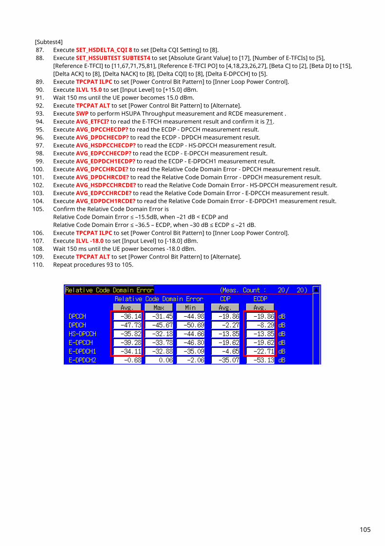
[Subtest4] 87. Execute SET_HSDELTA_CQI 8 to set [Delta CQI Setting] to [8]. 88. Execute SET_HSSUBTEST SUBTEST4 to set [Absolute Grant Value] to [17], [Number of E-TFCIs] to [5],
[Reference E-TFCI] to [11,67,71,75,81], [Reference E-TFCI PO] to [4,18,23,26,27], [Beta C] to [2], [Beta D] to [15], [Delta ACK] to [8], [Delta NACK] to [8], [Delta CQI] to [8], [Delta E-DPCCH] to [5].
89. Execute TPCPAT ILPC to set [Power Control Bit Pattern] to [Inner Loop Power Control]. 90. Execute ILVL 15.0 to set [Input Level] to [+15.0] dBm. 91. Wait 150 ms until the UE power becomes 15.0 dBm. 92. Execute TPCPAT ALT to set [Power Control Bit Pattern] to [Alternate]. 93. Execute SWP to perform HSUPA Throughput measurement and RCDE measurement . 94. Execute AVG_ETFCI? to read the E-TFCH measurement result and confirm it is 71. 95. Execute AVG_DPCCHECDP? to read the ECDP - DPCCH measurement result. 96. Execute AVG_DPDCHECDP? to read the ECDP - DPDCH measurement result. 97. Execute AVG_HSDPCCHECDP? to read the ECDP - HS-DPCCH measurement result. 98. Execute AVG_EDPCCHECDP? to read the ECDP - E-DPCCH measurement result. 99. Execute AVG_EDPDCH1ECDP? to read the ECDP - E-DPDCH1 measurement result.
100. Execute AVG_DPCCHRCDE? to read the Relative Code Domain Error - DPCCH measurement result. 101. Execute AVG_DPDCHRCDE? to read the Relative Code Domain Error - DPDCH measurement result. 102. Execute AVG_HSDPCCHRCDE? to read the Relative Code Domain Error - HS-DPCCH measurement result. 103. Execute AVG_EDPCCHRCDE? to read the Relative Code Domain Error - E-DPCCH measurement result. 104. Execute AVG_EDPDCH1RCDE? to read the Relative Code Domain Error - E-DPDCH1 measurement result. 105. Confirm the Relative Code Domain Error is
Relative Code Domain Error ≤ –15.5dB, when –21 dB < ECDP and Relative Code Domain Error ≤ –36.5 – ECDP, when –30 dB ≤ ECDP ≤ –21 dB.
106. Execute TPCPAT ILPC to set [Power Control Bit Pattern] to [Inner Loop Power Control]. 107. Execute ILVL -18.0 to set [Input Level] to [-18.0] dBm. 108. Wait 150 ms until the UE power becomes -18.0 dBm. 109. Execute TPCPAT ALT to set [Power Control Bit Pattern] to [Alternate]. 110. Repeat procedures 93 to 105.
105

Table 1.12-4 3GPP TS34.121 Table 5.13.2B.8: Nominal ECDP Ratios
Subtest in Table
C.11.1.3 Code Nominal Code
Domain Power Spreading Factor Nominal ECDP
1
DPCCH –18.5 256 –18.5
DPDCH –15.8 64 –21.8
HS-DPCCH –12.5 256 –12.5
E-DPCCH –16.5 256 –16.5
E-DPDCH –0.5 4 –18.6
2
DPCCH –14.0 256 –14.0
DPDCH –6.0 64 –12.0
HS-DPCCH –8.0 256 –8.0
E-DPCCH –8.0 256 –8.0
E-DPDCH –4.1 4 –22.2
3
DPCCH –14.6 256 –14.6
DPDCH –19.1 64 –25.1
HS-DPCCH –8.6 256 –8.6
E-DPCCH –8.6 256 –8.6
E-DPDCH1 –4.7 4 –22.8
E-DPDCH2 –4.7 4 –22.8
4
DPCCH –19.7 256 –19.7
DPDCH –2.2 64 –8.2
HS-DPCCH –13.7 256 –13.7
E-DPCCH –19.7 256 –19.7
E-DPDCH –4.7 4 –22.8
Table 1.12-5 3GPP TS34.121 Table 5.13.2B.9: Relative Code Domain Error Test Requirement
ECDP dB Relative Code Domain Error dB
–21 < ECDP ≤ –15.5
–30 ≤ ECDP ≤ –21 ≤ –36.5 – ECDP
ECDP < –30 No requirement
106

1.13. HSPA Evolution Measurement
1.13.1. E-DCH RF Test (TTI 2ms/16QAM) Location Registration Location registration with E-DCH RF Test (TTI 2ms/16QAM) required to connect with HSPA Evolution.
1. Execute PRESET_3GPP to initialize the parameter settings for 3GPP. 2. Execute CHCODING EDCHTEST to set [Channel Coding] to [E-DCH RF Test].
Execute CHCODING FIXREFCH to set [Channel Coding] to [Fixed Reference Channel] to test TS34.121 6.3B. 3. Execute HSUSET TTI2_16QAM to set [HSUPA Set of Parameters] to [TTI 2ms(16QAM)].
Execute HSHSET HSET8_64QAM to set to [H-Set8(64QAM)] to test TS34.121 6.3B. 4. Execute INTEGRITY ON to set [Integrity Protection] to [On]. 5. UE power On. 6. Execute CALLSTAT? and wait until the response returns 2(=Idle(Regist)).
1.13.2. E-DCH RF Test (TTI 2ms/16QAM) Connection Execute the following procedure (refer to location registration procedure of item 1.13.1 E-D~CH RF Test (TTI 2 ms/16QAM) after terminal location registration is completed.
1. Execute CALLSA to connect with E-DCH RF Test (TTI 2ms/16QAM). 2. Execute CALLSTAT? and wait until the response returns 7(=Test Loop Mode).
1.13.3. E-DCH RF Test (TTI 2ms/16QAM) Disconnection
1. Execute CALLSO to disconnect E-DCH RF Test (TTI 2ms/16QAM). 2. Execute CALLSTAT? and wait until the response returns 2(=Idle(Regist)).
1.13.4. Channel Change by Handover Measurement is usually executed for three frequency (L, M, and H) points. In this case, if the channel is switched by handover, the channel can be switched quickly because it is not necessary to reconnect. At handover, the Output Level is increased slightly so that handover does not fail. However, execution of any GPIB commands sent while handover is executing is delayed until handover is completed.
1. Perform TRX measurement with M channel. 2. Execute CHAN 9613 to handover to L channel. 3. Perform TRX measurement. 4. Execute CHAN 9887 to handover to H channel. 5. Perform TRX measurement.
107
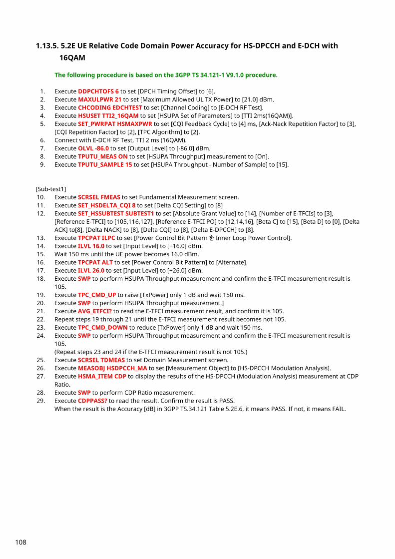
1.13.5. 5.2E UE Relative Code Domain Power Accuracy for HS-DPCCH and E-DCH with 16QAM
The following procedure is based on the 3GPP TS 34.121-1 V9.1.0 procedure.
1. Execute DDPCHTOFS 6 to set [DPCH Timing Offset] to [6]. 2. Execute MAXULPWR 21 to set [Maximum Allowed UL TX Power] to [21.0] dBm. 3. Execute CHCODING EDCHTEST to set [Channel Coding] to [E-DCH RF Test]. 4. Execute HSUSET TTI2_16QAM to set [HSUPA Set of Parameters] to [TTI 2ms(16QAM)]. 5. Execute SET_PWRPAT HSMAXPWR to set [CQI Feedback Cycle] to [4] ms, [Ack-Nack Repetition Factor] to [3],
[CQI Repetition Factor] to [2], [TPC Algorithm] to [2]. 6. Connect with E-DCH RF Test, TTI 2 ms (16QAM). 7. Execute OLVL -86.0 to set [Output Level] to [-86.0] dBm. 8. Execute TPUTU_MEAS ON to set [HSUPA Throughput] measurement to [On]. 9. Execute TPUTU_SAMPLE 15 to set [HSUPA Throughput - Number of Sample] to [15].
[Sub-test1] 10. Execute SCRSEL FMEAS to set Fundamental Measurement screen. 11. Execute SET_HSDELTA_CQI 8 to set [Delta CQI Setting] to [8] 12. Execute SET_HSSUBTEST SUBTEST1 to set [Absolute Grant Value] to [14], [Number of E-TFCIs] to [3],
[Reference E-TFCI] to [105,116,127], [Reference E-TFCI PO] to [12,14,16], [Beta C] to [15], [Beta D] to [0], [Delta ACK] to[8], [Delta NACK] to [8], [Delta CQI] to [8], [Delta E-DPCCH] to [8].
13. Execute TPCPAT ILPC to set [Power Control Bit Pattern を Inner Loop Power Control]. 14. Execute ILVL 16.0 to set [Input Level] to [+16.0] dBm. 15. Wait 150 ms until the UE power becomes 16.0 dBm. 16. Execute TPCPAT ALT to set [Power Control Bit Pattern] to [Alternate]. 17. Execute ILVL 26.0 to set [Input Level] to [+26.0] dBm. 18. Execute SWP to perform HSUPA Throughput measurement and confirm the E-TFCI measurement result is
105. 19. Execute TPC_CMD_UP to raise [TxPower] only 1 dB and wait 150 ms. 20. Execute SWP to perform HSUPA Throughput measurement.] 21. Execute AVG_ETFCI? to read the E-TFCI measurement result, and confirm it is 105. 22. Repeat steps 19 through 21 until the E-TFCI measurement result becomes not 105. 23. Execute TPC_CMD_DOWN to reduce [TxPower] only 1 dB and wait 150 ms. 24. Execute SWP to perform HSUPA Throughput measurement and confirm the E-TFCI measurement result is
105. (Repeat steps 23 and 24 if the E-TFCI measurement result is not 105.)
25. Execute SCRSEL TDMEAS to set Domain Measurement screen. 26. Execute MEASOBJ HSDPCCH_MA to set [Measurement Object] to [HS-DPCCH Modulation Analysis]. 27. Execute HSMA_ITEM CDP to display the results of the HS-DPCCH (Modulation Analysis) measurement at CDP
Ratio. 28. Execute SWP to perform CDP Ratio measurement. 29. Execute CDPPASS? to read the result. Confirm the result is PASS.
When the result is the Accuracy [dB] in 3GPP TS.34.121 Table 5.2E.6, it means PASS. If not, it means FAIL.
108

Chart 1.13-1 3GPP TS34.121 Table 5.2E.5: UE relative code domain power nominal ratios
Sub-Test in Table C.11.1.4
Meas Point
Expected Relative Code Domain Power in dB
DPCCH HS-DPCCH E-DPCCH E-DPDCH 1
E-DPDCH 2
E-DPDCH 3,4
1 1 -9.6 -3.6 -3.6 -19.1 OFF OFF
2 -13.4 -7.4 -7.4 -7.4 -7.4 -9.4
3 -9.6 -3.6 -3.6 -19.1 OFF OFF
Chart 1.13-2 3GPP TS34.121 Table 5.2E.6: UE relative code domain power accuracy test requirements, HSDPA and E-DCH with 16QAM
Nominal CDP ratio Accuracy (dB) ≥ -10 dB ±1.7
-10 dB to ≥ -15 dB ±2.3
-15 dB ≥ -20 dB ±2.9
-20 dB ≥ -30 dB [±3.5]
109

1.13.6. 5.13.1AAA EVM and IQ origin offset for HS-DPCCH and E-DCH with 16 QAM
The following procedure is based on the 3GPP TS 34.121-1 V9.1.0 procedure.
1. Execute DDPCHTOFS 6 to set [DPCH Timing Offset] to [6]. 2. Execute MAXULPWR 21 to set [Maximum Allowed UL TX Power] to [21.0] dBm. 3. Execute CHCODING EDCHTEST to set [Channel Coding] [E-DCH RF Test]. 4. Execute HSUSET TTI2_16QAM to set [HSUPA Set of Parameters] to [TTI 2ms(16QAM)]. 5. Execute SET_PWRPAT HSMAXPWR to set [CQI Feedback Cycle] to [4] ms, [Ack-Nack Repetition Factor] to [3],
[CQI Repetition Factor] to [2], [TPC Algorithm] to [2]. 6. Connect with E-DCH RF Test, TTI 2 ms (16QAM). 7. Execute OLVL -86.0 to set [Output Level] to [-86.0] dBm. 8. Execute MOD_MEAS ON to set [Modulation Analysis] to [On]. 9. Execute MOD_AVG 20 to set [Average Count] of Modulation Analysis measurement to [20] times.
[Sub-test1] 10. Execute SCRSEL FMEAS to set Fundamental Measurement screen. 11. Execute SET_HSDELTA_CQI 8 to set [Delta CQI Setting] to [8]. 12. Execute SET_HSSUBTEST SUBTEST1 to set [Absolute Grant Value] to [14], [Number of E-TFCIs] to [3],
[Reference E-TFCI] to [105,116,127], [Reference E-TFCI PO] to [12,14,16], [Beta C] to 15, [Beta D] to [0], [Delta ACK] to [8], [Delta NACK] to [8], [Delta CQI] to [8], [Delta E-DPCCH] to [8].
13. Execute TPCPAT ILPC to set [Power Control Bit Pattern] to [Inner Loop Power Control]. 14. Execute ILVL -28.0 to set [Input Level] to [-28.0] dBm. 15. Wait 150 ms until the UE power becomes -28.0 dBm. 16. Execute TPCPAT ALT to set [Power Control Bit Pattern] to [Alternate]. 17. Execute SWP to perform Modulation Analysis measurement. 18. Execute AVG_ORGNOFS? to read Origin Offset measurement result. 19. Confirm the measurement result is <16.5 dB.
110
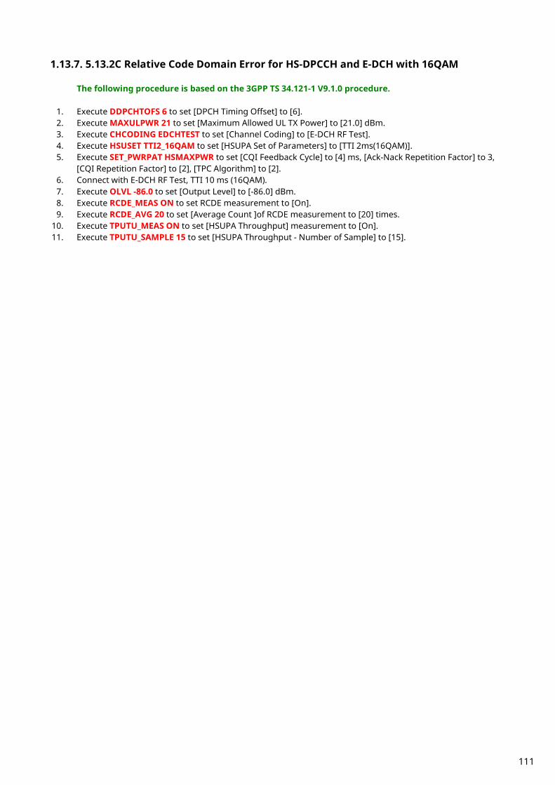
1.13.7. 5.13.2C Relative Code Domain Error for HS-DPCCH and E-DCH with 16QAM
The following procedure is based on the 3GPP TS 34.121-1 V9.1.0 procedure.
1. Execute DDPCHTOFS 6 to set [DPCH Timing Offset] to [6]. 2. Execute MAXULPWR 21 to set [Maximum Allowed UL TX Power] to [21.0] dBm. 3. Execute CHCODING EDCHTEST to set [Channel Coding] to [E-DCH RF Test]. 4. Execute HSUSET TTI2_16QAM to set [HSUPA Set of Parameters] to [TTI 2ms(16QAM)]. 5. Execute SET_PWRPAT HSMAXPWR to set [CQI Feedback Cycle] to [4] ms, [Ack-Nack Repetition Factor] to 3,
[CQI Repetition Factor] to [2], [TPC Algorithm] to [2]. 6. Connect with E-DCH RF Test, TTI 10 ms (16QAM). 7. Execute OLVL -86.0 to set [Output Level] to [-86.0] dBm. 8. Execute RCDE_MEAS ON to set RCDE measurement to [On]. 9. Execute RCDE_AVG 20 to set [Average Count ]of RCDE measurement to [20] times.
10. Execute TPUTU_MEAS ON to set [HSUPA Throughput] measurement to [On]. 11. Execute TPUTU_SAMPLE 15 to set [HSUPA Throughput - Number of Sample] to [15].
111
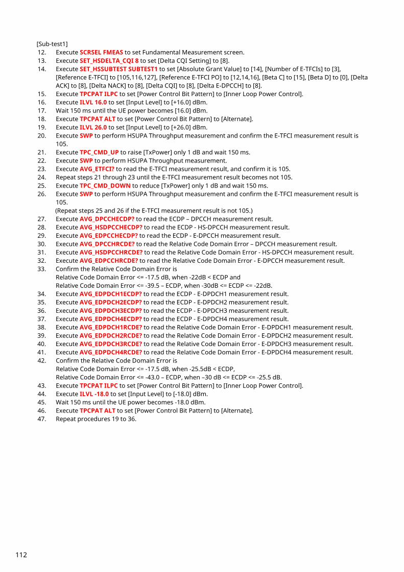
[Sub-test1] 12. Execute SCRSEL FMEAS to set Fundamental Measurement screen. 13. Execute SET_HSDELTA_CQI 8 to set [Delta CQI Setting] to [8]. 14. Execute SET_HSSUBTEST SUBTEST1 to set [Absolute Grant Value] to [14], [Number of E-TFCIs] to [3],
[Reference E-TFCI] to [105,116,127], [Reference E-TFCI PO] to [12,14,16], [Beta C] to [15], [Beta D] to [0], [Delta ACK] to [8], [Delta NACK] to [8], [Delta CQI] to [8], [Delta E-DPCCH] to [8].
15. Execute TPCPAT ILPC to set [Power Control Bit Pattern] to [Inner Loop Power Control]. 16. Execute ILVL 16.0 to set [Input Level] to [+16.0] dBm. 17. Wait 150 ms until the UE power becomes [16.0] dBm. 18. Execute TPCPAT ALT to set [Power Control Bit Pattern] to [Alternate]. 19. Execute ILVL 26.0 to set [Input Level] to [+26.0] dBm. 20. Execute SWP to perform HSUPA Throughput measurement and confirm the E-TFCI measurement result is
105. 21. Execute TPC_CMD_UP to raise [TxPower] only 1 dB and wait 150 ms. 22. Execute SWP to perform HSUPA Throughput measurement. 23. Execute AVG_ETFCI? to read the E-TFCI measurement result, and confirm it is 105. 24. Repeat steps 21 through 23 until the E-TFCI measurement result becomes not 105. 25. Execute TPC_CMD_DOWN to reduce [TxPower] only 1 dB and wait 150 ms. 26. Execute SWP to perform HSUPA Throughput measurement and confirm the E-TFCI measurement result is
105. (Repeat steps 25 and 26 if the E-TFCI measurement result is not 105.)
27. Execute AVG_DPCCHECDP? to read the ECDP – DPCCH measurement result. 28. Execute AVG_HSDPCCHECDP? to read the ECDP - HS-DPCCH measurement result. 29. Execute AVG_EDPCCHECDP? to read the ECDP - E-DPCCH measurement result. 30. Execute AVG_DPCCHRCDE? to read the Relative Code Domain Error – DPCCH measurement result. 31. Execute AVG_HSDPCCHRCDE? to read the Relative Code Domain Error - HS-DPCCH measurement result. 32. Execute AVG_EDPCCHRCDE? to read the Relative Code Domain Error - E-DPCCH measurement result. 33. Confirm the Relative Code Domain Error is
Relative Code Domain Error <= -17.5 dB, when -22dB < ECDP and Relative Code Domain Error <= -39.5 – ECDP, when -30dB <= ECDP <= -22dB.
34. Execute AVG_EDPDCH1ECDP? to read the ECDP - E-DPDCH1 measurement result. 35. Execute AVG_EDPDCH2ECDP? to read the ECDP - E-DPDCH2 measurement result. 36. Execute AVG_EDPDCH3ECDP? to read the ECDP - E-DPDCH3 measurement result. 37. Execute AVG_EDPDCH4ECDP? to read the ECDP - E-DPDCH4 measurement result. 38. Execute AVG_EDPDCH1RCDE? to read the Relative Code Domain Error - E-DPDCH1 measurement result. 39. Execute AVG_EDPDCH2RCDE? to read the Relative Code Domain Error - E-DPDCH2 measurement result. 40. Execute AVG_EDPDCH3RCDE? to read the Relative Code Domain Error - E-DPDCH3 measurement result. 41. Execute AVG_EDPDCH4RCDE? to read the Relative Code Domain Error - E-DPDCH4 measurement result. 42. Confirm the Relative Code Domain Error is
Relative Code Domain Error <= -17.5 dB, when -25.5dB < ECDP, Relative Code Domain Error <= -43.0 – ECDP, when –30 dB <= ECDP <= -25.5 dB.
43. Execute TPCPAT ILPC to set [Power Control Bit Pattern] to [Inner Loop Power Control]. 44. Execute ILVL -18.0 to set [Input Level] to [-18.0] dBm. 45. Wait 150 ms until the UE power becomes -18.0 dBm. 46. Execute TPCPAT ALT to set [Power Control Bit Pattern] to [Alternate]. 47. Repeat procedures 19 to 36.
112
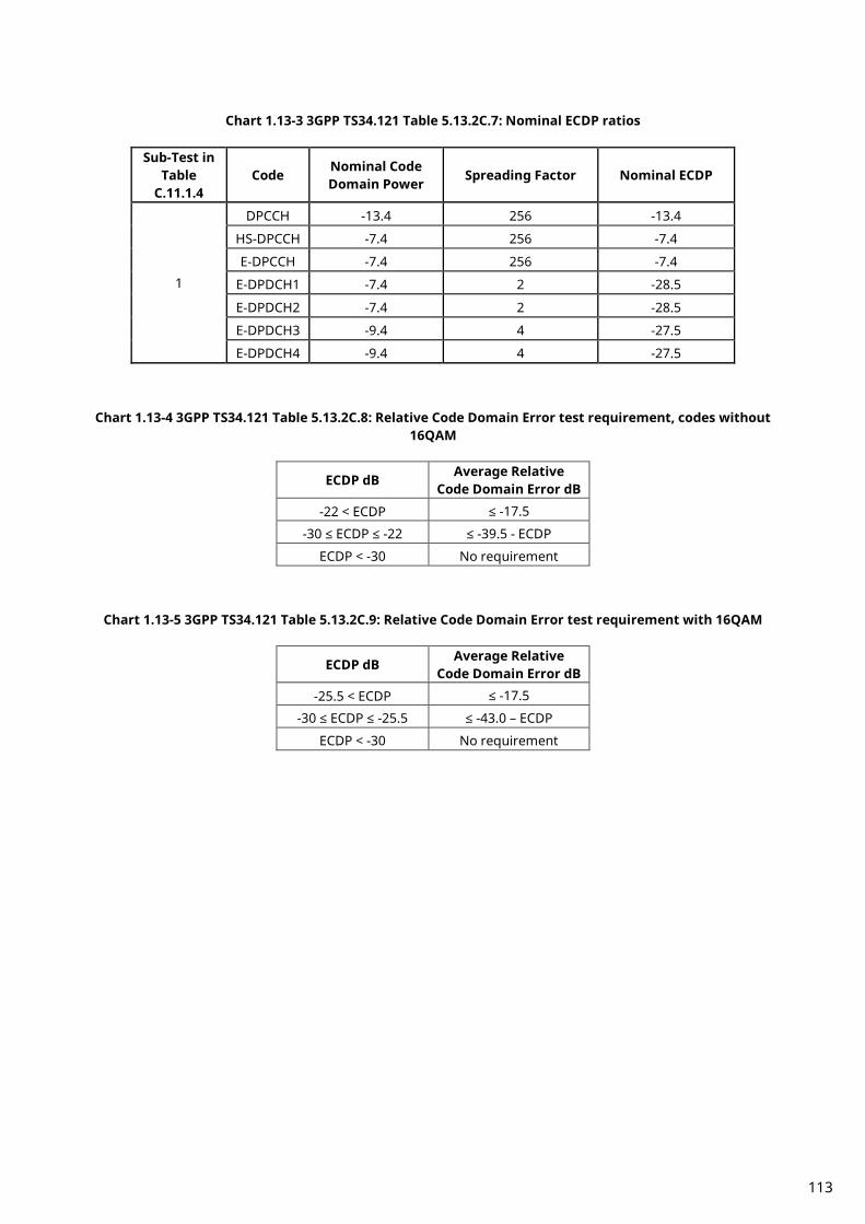
Chart 1.13-3 3GPP TS34.121 Table 5.13.2C.7: Nominal ECDP ratios
Sub-Test in Table
C.11.1.4 Code Nominal Code
Domain Power Spreading Factor Nominal ECDP
1
DPCCH -13.4 256 -13.4
HS-DPCCH -7.4 256 -7.4
E-DPCCH -7.4 256 -7.4
E-DPDCH1 -7.4 2 -28.5
E-DPDCH2 -7.4 2 -28.5
E-DPDCH3 -9.4 4 -27.5
E-DPDCH4 -9.4 4 -27.5
Chart 1.13-4 3GPP TS34.121 Table 5.13.2C.8: Relative Code Domain Error test requirement, codes without 16QAM
ECDP dB Average Relative Code Domain Error dB
-22 < ECDP ≤ -17.5
-30 ≤ ECDP ≤ -22 ≤ -39.5 - ECDP
ECDP < -30 No requirement
Chart 1.13-5 3GPP TS34.121 Table 5.13.2C.9: Relative Code Domain Error test requirement with 16QAM
ECDP dB Average Relative Code Domain Error dB
-25.5 < ECDP ≤ -17.5
-30 ≤ ECDP ≤ -25.5 ≤ -43.0 – ECDP
ECDP < -30 No requirement
113

1.13.8. 6.3B Maximum Input Level for HS-PDSCH Reception (64QAM)
The following procedure is based on the 3GPP TS 34.121-1 V9.1.0 procedure. This test connects with Fixed Reference Channel H-Set8 (64QAM).
1. Execute ULGAINPAR 8,15,8,8,8 to set [Beta C] to [8], [Beta D] to [15], [Delta ACK] to [8], [Delta NACK] to [8],
[Delta CQI] to [8]. 2. Execute TPCALGO 2 to set [TPC Algorithm] to [2]. 3. Execute CHAN 9750 to set to M channel (for Band I). 4. Execute CHCODING FIXREFCH to set [Channel Coding] to [Fixed Reference Channel]. 5. Execute HSHSET HSET8_64QAM to set [HSUPA Set of Parameters] to [H-Set8(64QAM)]. 6. Connect with Fixed Reference Channel, H-Set8(64QAM). 7. Execute TPCPAT ILPC to set [Power Control Bit Pattern] to [Inner Loop Power Control]. 8. Execute ILVL 0.0 to set [Input Level] to [0.0] dBm. 9. Wait 100 ms until the UE power becomes [0.0] dBm.
10. Execute TPCPAT ALT to set [Power Control Bit Pattern] to [Alternate]. 11. Execute OLVL -25.7 to set [Output Level] to [-25.7] dBm. 12. Execute DDPCHPWR -13.0 to set [DPCH_Ec/Ior] to [-13.0] dB. 13. Execute HSSCCHPWR -13.0 to set [HS-SCCH_Ec/Ior] to [-13.0 dB]. 14. Execute HSPDSCHPWR -2.0 to set [HS-PDSCH_Ec/Ior] to [-2.0] dB. 15. Execute TPUT_MEAS ON to set [HSDPA Throughput] measurement to [On]. 16. Execute TPUT_SAMPLE 1000 to set number of HSDPA Throughput measurement sample to [1000] Block. 17. Execute TPUT_LIMIT 11800 to set lower limit of HSDPA Throughput measurement to [11800] kbps. 18. Execute SWP to perform HSDPA Throughput measurement. 19. Execute TPUTPASS? to read HSDPA Throughput measurement result. Confirm the result is PASS.
114
1.14. DC-HSDPA Measurement * This chapter explains measurements when Phone1 and Phone 2 are used as Serving Cell and Secondary Serving Cell, respectively for DC-HSDPA connection.
1.14.1. Synchronization of Frame Timing between 2 cells Synchronizing frame timing between 2 cells is required when connecting with DC-HSDPA.
1. [Phone1] Execute ENTERSYNC IN_SLAVE to be slave condition of frame timing synchronization. 2. [Phone2] Execute ENTERSYNC MASTER to perform frame timing synchronization. 3. [Phone1] Execute ENTERSYNC? to check response becomes 1 (synchronized).
1.14.2. Location Registration for DC-HSDPA Location registration with Combined is required when connecting using DC-HSDPA.
1. [Phone1-2] Execute PRESET_3GPP to preset parameters for 3GPP. 2. [Phone1-2] Execute CHCODING FRC_DCHSDPA to set [Channel Coding] to [FRC for DC-HSDPA]. 3. [Phone1] Execute INTEGRITY ON to set [Integrity Protection] to [On]. 4. [Phone1] Execute REGMODE COMBINED to set [Registration Mode] to [Combined]. 5. [Phone2] Execute LVL OFF to set [Output Level Total)] to [Off] for Secondary Serving Cell. 6. [Phone2] Execute CALLPROC OFF to set [Call Processing] of Secondary Serving Cell to [Off] to output each
channel. 7. Turn on the UE power. 8. [Phone1] Execute CALLSTAT? and wait until the response becomes 2 (= Idle (Regist)).
1.14.3. Connection with DC-HSDPA The process after location registration is shown below. (See 1.14.2 Location Registration for DC-HSDPA.) [H-Set12(QPSK) connection example]
1. [Phone1] Execute DCHSHSET HSET12_QPSK to set [Channel Coding] to [FRC for DC-HSDPA]&[H-Set12(QPSK)].
2. [Phone1] Execute S_DLCHAN 10725 to set [Second Cell UARFCN] to [10725]CH for Secondary Serving Cell (when the DL channel of Serving Cell is 10700).
3. [Phone1] Execute CALLSA to connect with DC-HSDPA 4. [Phone1] Execute CALLSTAT? and wait until the response becomes 7 (=Test Loop Mode). 5. [Phone2] Execute DCHSHSET HSET12_QPSK to set [Channel Coding] to [FRC for
DC-HSDPA]&[H-Set12(QPSK)]. 6. [Phone2] Execute DLCHAN 10725 to set [DL Channel & Frequency] to [10725]CH for Secondary Serving Cell. 7. [Phone2] Execute LVL ON to set [Output Level(Total)] to [On] for Secondary Serving Cell.
1.14.4. Disconnection with DC-HSDPA
1. [Phone1] Execute CALLSO to disconnect with DC-HSDPA (by pressing “End Call” key). 2. [Phone1] Execute CALLSTAT? and wait until the response becomes 2 (=Idle(Regist)).
115

1.14.5. Channel Switching using Handover Usually, measurement is performed at three frequency points (L, M, H). In this case, the Channel can be switched quickly without reconnection by switching it at handover with a higher output level and Beta C for UL DPCCH. When a GPIB command is sent during handover, it waits until handover ends.
1. [Phone1] Execute RX measurement with M channel. 2. [Phone1] Execute S_DLCHAN 10588 to set [Second Cell UARFCN] to [10588]CH for Secondary Serving Cell. 3. [Phone1] Execute CHAN 9613 (or DLCHAN 10563) to set [UL Channel & Frequency] to [9613]CH and perform
handover to L channel. 4. [Phone2] Execute DLCHAN 10588 to set [DL Channel & Frequency] to [10588]CH for Secondary Serving Cell. 5. [Phone1] Execute RX measurement. 6. [Phone1] Execute S_DLCHAN 10812 to set [Second Cell UARFCN] to [10812]CH for Secondary Serving Cell. 7. [Phone1] Execute CHAN 9887 (or DLCHAN 10837) to set [UL Channel & Frequency] to [9887]CH and perform
handover to handover to H channel. 8. [Phone2] Execute DLCHAN 10812 to set [DL Channel & Frequency] to [10812]CH for Secondary Serving Cell. 9. [Phone1] Execute RX measurement.
116

1.14.7. 6.2A Reference Sensitivity Level for DC-HSDPA
1. [Phone1] Execute ULGAINPAR 8,15,8,8,8 to set [Beta C] to [8], [Beta D] to [15], [Delta ACK] to [8], [Delta NACK] to [8], [Delta CQI] to [8].
2. [Phone1] Execute ILVL 35.0 to set [Input Level] to [+35.0] dBm. 3. [Phone1] Execute S_DLCHAN 10725 to set [Second Cell UARFCN] to [10725]CH for Secondary Serving Cell. 4. [Phone1] Execute CHAN 9750 (or DLCHAN 10700) to set [UL Channel & Frequency] to [9750]CH Cell (M
channel, when Band I). 5. [Phone2] Execute DLCHAN 10725 to set [DL Channel & Frequency] to [10725]CH for Secondary Serving Cell
Cell (M channel, when Band I). 6. Connect with Fixed Reference Channel H-Set12(QPSK) (see 1.14.3 Connection with DC-HSDPA). 7. [Phone1] Execute TPCPAT ALL1 to set [Power Control Bit Pattern] to [ALL 1]. 8. [Phone1-2] Execute OLVL -102 to set [Output Level(Total)] to [-102] dBm (when Band I). 9. [Phone1-2] Execute HSSCCHPWR -9.0 to set [HS-SCCH_Ec/Ior] to [-9.0] dB.
10. [Phone1-2] Execute HSPDSCHPWR -10.3 to set [HS-PDSCH_Ec/Ior] to [-10.3] dB. 11. [Phone1] Execute TPUT_MEAS ON to set [HSDPA Throughput measurement] to [On]. 12. [Phone1] Execute TPUT_SAMPLE 1000 to set [Number of Sample] at HSDPA Throughput to [1000] Block. 13. [Phone1] Execute SWP to perform HSDPA Throughput measurement. 14. [Phone1] Execute TPUT_BLER? to read the Block Error Rate measurement result of Serving Cell. Confirm the
measurement result is lower than 0.1. 15. [Phone1] Execute TPUT_S_BLER? to read the Block Error Rate measurement result of Secondary Serving Cell.
Confirm the measurement result is lower than 0.1.
117
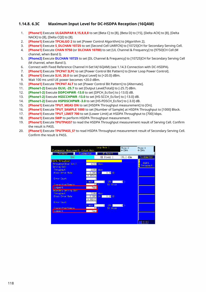
1.14.8. 6.3C Maximum Input Level for DC-HSDPA Reception (16QAM)
1. [Phone1] Execute ULGAINPAR 8,15,8,8,8 to set [Beta C] to [8], [Beta D] to [15], [Delta ACK] to [8], [Delta NACK] to [8], [Delta CQI] to [8].
2. [Phone1] Execute TPCALGO 2 to set [Power Control Algorithm] to [Algorithm 2]. 3. [Phone1] Execute S_DLCHAN 10725 to set [Second Cell UARFCN] to [10725]CH for Secondary Serving Cell. 4. [Phone1] Execute CHAN 9750 (or DLCHAN 10700) to set [UL Channel & Frequency] to [9750]CH Cell (M
channel, when Band I). 5. [Phone2] Execute DLCHAN 10725 to set [DL Channel & Frequency] to [10725]CH for Secondary Serving Cell
(M channel, when Band I). 6. Connect with Fixed Reference Channel H-Set1A(16QAM) (see 1.14.3 Connection with DC-HSDPA). 7. [Phone1] Execute TPCPAT ILPC to set [Power Control Bit Pattern] to [Inner Loop Power Control]. 8. [Phone1] Execute ILVL 20.0 to set [Input Level] to [+20.0] dBm. 9. Wait 100 ms until UE power becomes +20.0 dBm.
10. [Phone1] Execute TPCPAT ALT to set [Power Control Bit Pattern] to [Alternate]. 11. [Phone1-2] Execute OLVL -25.7 to set [Output Level(Total)] to [-25.7] dBm. 12. [Phone1-2] Execute DDPCHPWR -13.0 to set [DPCH_Ec/Ior] to [-13.0] dB. 13. [Phone1-2] Execute HSSCCHPWR -13.0 to set [HS-SCCH_Ec/Ior] to [-13.0] dB. 14. [Phone1-2] Execute HSPDSCHPWR -3.0 to set [HS-PDSCH_Ec/Ior] to [-3.0] dB. 15. [Phone1] Execute TPUT_MEAS ON to set [HSDPA Throughput measurement] to [On]. 16. [Phone1] Execute TPUT_SAMPLE 1000 to set [Number of Sample] at HSDPA Throughput to [1000] Block. 17. [Phone1] Execute TPUT_LIMIT 700 to set [Lower Limit] at HSDPA Throughput to [700] kbps. 18. [Phone1] Execute SWP to perform HSDPA Throughput measurement. 19. [Phone1] Execute TPUTPASS? to read the HSDPA Throughput measurement reault of Serving Cell. Confirm
the result is PASS. 20. [Phone1] Execute TPUTPASS_S? to read HSDPA Throughput measurement result of Secondary Serving Cell.
Confirm the result is PASS.
118

1.14.9. 6.3D Maximum Input Level for DC-HSDPA Reception (64QAM)
1. [Phone1] Execute ULGAINPAR 8,15,8,8,8 to set [Beta C] to [8], [Beta D] to [15], [Delta ACK] to 8, [Delta NACK] to [8], [Delta CQI] to [8].
2. [Phone1] Execute TPCALGO 2 to set [Power Control Algorithm] to [Algorithm 2]. 3. [Phone1] Execute S_DLCHAN 10725 to set [Second Cell UARFCN] to [10725]CH for Secondary Serving Cell. 4. [Phone1] Execute CHAN 9750 (or DLCHAN 10700) to set [UL Channel & Frequency] to [9750]CH (M channel,
when Band I). 5. [Phone2] Execute DLCHAN 10725 to set [DL Channel & Frequency] to [10725]CH for Secondary Serving Cell
(M channel, when Band I). 6. Connect with Fixed Reference Channel H-Set8A(64QAM) (see 1.14.3 Connection with DC-HSDPA). 7. [Phone1] Execute TPCPAT ILPC to set [Power Control Bit Pattern] to [Inner Loop Power Control]. 8. [Phone1] Execute ILVL 0.0 to set [Input Level] to [0.0] dBm. 9. Wait 100 ms until UE power becomes 0.0 dBm.
10. [Phone1] Execute TPCPAT ALT to set [Power Control Bit Pattern] to [Alternate]. 11. [Phone1-2] Execute OLVL -25.7 to set [Output Level(Total)] to [-25.7] dBm. 12. [Phone1-2] Execute DDPCHPWR -13.0 to set [DPCH_Ec/Ior] to [-13.0] dB. 13. [Phone1-2] Execute HSSCCHPWR -13.0 to set [HS-SCCH_Ec/Ior] to [-13.0] dB. 14. [Phone1-2] Execute HSPDSCHPWR -2.0 to set [HS-PDSCH_Ec/Ior] to [-2.0] dB. 15. [Phone1] Execute TPUT_MEAS ON to set [HSDPA Throughput measurement] to [On]. 16. [Phone1] Execute TPUT_SAMPLE 1000 to set [Number of Sample] ot HSDPA Throughput to [1000] Block. 17. [Phone1] Execute TPUT_LIMIT 11800 to set [Lower Limit] at HSDPA Throughput to [11800] kbps. 18. [Phone1] Execute SWP to perform HSDPA Throughput measurement. 19. [Phone1] Execute TPUTPASS? to read the HSDPA Throughput measurement result of Serving Cell. Confirm
the result is PASS. 20. [Phone1] Execute TPUTPASS_S? to read the HSDPA Throughput measurement result of Secondary Serving
Cell. Confirm the result is PASS.
119
1.15. 4C-HSDPA Measurement
1.15.1. Connection and Disconnection with Single band 4C-HSDPA
1.15.1.1. Location Registration for Single band 4C-HSDPA Location registration with Combined is required when connecting using Single band 4C-HSDPA.
1. Execute PRESET_3GPP to initialize the parameter settings for 3GPP. 2. Execute CHCODING FRC_MCHSDPA to set [Channel Coding] to [FRC for MC-HSDPA]. 3. Execute INTEGRITY ON to set [Integrity Protection] to [On]. 4. Execute REGMODE COMBINED to set [Registration Mode] to [Combined]. 5. Turn on the UE power. 6. Execute CALLSTAT? and wait until the response becomes 2 (= Idle (Regist)).
1.15.1.2. Connection with Single band 4C-HSDPA The process after location registration is shown below. (See 1.15.1.1 Location Registration for Single band 4C-HSDPA.) [H-Set1B (16QAM) connection example]
1. Execute TTL_SERVING_CELL 3 to set [Total Serving Cells] to [3]. 2. Execute MCHSHSET HSET1B_16QAM to set [H-Set] to [H-Set1B (16QAM)]. 3. Execute CALLSA to connect with 4C-HSDPA. 4. Execute CALLSTAT? and wait until the response becomes 7 (=Test Loop Mode).
1.15.1.3. Disconnection with Single Band 4C-HSDPA
1. Execute CALLSO to disconnect with 4C-HSDPA (by pressing “End Call” key). 2. Execute CALLSTAT? and wait until the response becomes 2 (=Idle(Regist)).
1.15.1.4. Channel Switching using Handover(Single band 4C-HSDPA) Usually, measurement is performed at three frequency points (L, M, H). In this case, the Channel can be switched quickly without reconnection by switching it at handover with a higher output level and Beta C for UL DPCCH. When a GPIB command is sent during handover, it waits until handover ends.
1. Execute RX measurement with M channel. 2. Execute CHAN 9613 (or DLCHAN 10563) to set [UL Channel & Frequency] to [9613]CH and perform handover
to L channel. (Secondary Serving Cell1 and Secondary serving Cell2 are set automatically. When the DL channel of Serving Cell is 10563, the Second Serving Cell1 is 10588 and the Second Serving Cell2 is 10613.)
3. Execute RX measurement.
120

1.15.2. Connection and Disconnection with Dual band 4C-HSDPA * This section explains measurements when Phone1 and Phone 2 are used as Serving Cell and Secondary Serving Cell, respectively for Dual band 4C-HSDPA connection.
1.15.2.1. Synchronization of Frame Timing between 2 cells Synchronizing frame timing between 2 cells is required when connecting with Dual band 4C-HSDPA.
1. [Phone1] Execute ENTERSYNC IN_SLAVE to be slave condition of frame timing synchronization. 2. [Phone2] Execute ENTERSYNC MASTER to perform frame timing synchronization. 3. [Phone1] Execute ENTERSYNC? to check response becomes 1 (synchronized).
1.15.2.2. Location Registration for Dual Band 4C-HSDPA Location registration with Combined is required when connecting using Dual band 4C-HSDPA.
1. [Phone1-2] Execute PRESET_3GPP to preset parameters for 3GPP. 2. [Phone1-2] Execute CHCODING FRC_MCHSDPA to set [Channel Coding] to [FRC for MC-HSDPA]. 3. [Phone1] Execute INTEGRITY ON to set [Integrity Protection] to [On]. 4. [Phone1] Execute REGMODE COMBINED to set [Registration Mode] to [Combined]. 5. [Phone2] Execute LVL OFF to set [Output Level Total)] to [Off] for Secondary Serving Cell. 6. [Phone2] Execute CALLPROC OFF to set [Call Procesing] of Secondary Serving Cell to [Off] to output each
channel. 7. Turn on the UE power. 8. [Phone1] Execute CALLSTAT? and wait until the response becomes 2 (= Idle (Regist)).
121

1.15.2.3. Connection with Dual Band 4C-HSDPA The process after location registration is shown below. (See 1.15.2.1 Location Registration for Dual band 4C-HSDPA.) [H-Set1C (16QAM) connection example]
1. [Phone1] Execute TTL_SERVING_CELL 4 to set [Total Serving Cells] to [4]. 2. [Phone1] Execute CELL_ASSIGN 3CELL_1 to set [Serving Cells Assignment] to [3Cells-1]. 3. [Phone1] Execute MCHSHSET HSET1C_16QAM to set [H-Set] to [H-Set1C (16QAM)]. 4. [Phone1] Execute S1_DLCHAN 10725 to set [Second Cell UARFCN 1st] to [10725]CH for Secondary Serving
Cell1 (for Band I) 5. [Phone1] Execute S2_DLCHAN 10750 to set [Second Cell UARFCN 2nd] to [10750]CH for Secondary Serving
Cell2 (for Band I). 6. [Phone1] Execute S3_DLCHAN 4625 to set [Second Cell UARFCN 3rd] to [4625]CH for Secondary Serving Cell3
(for Band VIII). 7. [Phone1] Execute CALLSA to connect with 4C-HSDPA. 8. [Phone1] Execute CALLSTAT? and wait until the response becomes 7 (=Test Loop Mode) 9. [Phone2] Execute TTL_SERVING_CELL 4 to set [Total Serving Cells] to [4].
10. [Phone2] Execute CELL_ASSIGN 1CELL to set [Serving Cells Assignment] to [1Cells]. 11. [Phone2] Execute MCHSHSET HSET1C_16QAM to set [H-Set] to [H-Set1C (16QAM)]. 12. [Phone2] Execute DLCHAN 4625 to set [Second Cell UARFCN 3rd] to [4625]CH for Secondary Serving Cell3
(for Band VIII). 13. [Phone2] Execute LVL ON to set [Output Level(Total)] to [On] for Secondary Serving Cell.
1.15.2.4. Disconnection with Dual Band 4C-HSDPA
1. [Phone1] Execute CALLSO to disconnect with 4C-HSDPA (by pressing “End Call” key). 2. [Phone1] Execute CALLSTAT? and wait until the response becomes 2 (=Idle(Regist)).
122
1.15.2.5. Channel Switching using Handover(Dual band 4C-HSDPA) Usually, measurement is performed at three frequency points (L, M, H). In this case, the Channel can be switched quickly without reconnection by switching it at handover with a higher output level and Beta C for UL DPCCH. When a GPIB command is sent during handover, it waits until handover ends.
1. [Phone1] Execute RX measurement with M channel. 2. [Phone1] Execute S1_DLCHAN 10588 to set [Second Cell UARFCN 1st] to [10588]CH for Secondary Serving
Cell1 (for Band I). 3. [Phone1] Execute S2_DLCHAN 10613 to set [Second Cell UARFCN 2nd] to [10613]CH for Secondary Serving
Cell2 (for Band I). 4. [Phone1] Execute S3_DLCHAN 4700 to set [Second Cell UARFCN 3rd] to [4700]CH for Secondary Serving Cell3
(for Band VIII). 5. [Phone1] Execute CHAN 9613 (or DLCHAN 10563) to set [UL Channel & Frequency] to [9613]CH and perform
handover to L channel. 6. [Phone2] Execute DLCHAN 4700 to set [Second Cell UARFCN 3rd] to [4700]CH for Secondary Serving Cell3
(for Band VIII). 7. [Phone1] Execute RX measurement. 8. [Phone1] Execute S1_DLCHAN 10812 to set [Second Cell UARFCN 1st] to [10812]CH for Secondary Serving
Cell1 (for Band I). 9. [Phone1] Execute S2_DLCHAN 10787 to set [Second Cell UARFCN 2nd] to [10787]CH for Secondary Serving
Cell2 (for Band I). 10. [Phone1] Execute S3_DLCHAN 4800 to set [Second Cell UARFCN 3rd] to [4800]CH for Secondary Serving Cell3
(for Band VIII). 11. [Phone1] Execute CHAN 9887 (or DLCHAN 10837) to set [UL Channel & Frequency] to [9887]CH and perform
handover to X channel. 12. [Phone2] Execute DLCHAN 4700 to set [Second Cell UARFCN 3rd] to [4700]CH for Secondary Serving Cell3
(for Band VIII). 13. [Phone1] Execute RX measurement.
123

1.15.3. 6.2C Reference Sensitivity Level for Single band 4C-HSDPA
1. Execute ULGAINPAR 8,15,8,8,8 to set [Beta C] to [8], [Beta D] to [15], [Delta ACK] to [8], [Delta NACK] to [8], [Delta CQI] to [8].
2. Execute ILVL 35.0 to set [Input Level] to [+35.0] dBm. 3. Execute CQIFEEDBACK 4 to set [CQI Feedback Cycle] to [4 ms]. 4. Execute CHAN 9750 (or DLCHAN 10700) to set [UL Channel & Frequency] to [9750]CH Cell (M channel, for
Band I). 5. Connect with Fixed Reference Channel H-Set1B (16QAM) (see 1.15.1 Connection and Disconnection with
Single band 4C-HSDPA). 6. Execute TPCPAT ALL1 to set [Power Control Bit Pattern] to [ALL 1]. 7. Execute OLVL -102 to set [Output Level(Total)] to [-102] dBm (for Band I). 8. Execute HSSCCHPWR -9.0 to set [HS-SCCH_Ec/Ior] to [-9.0] dB. 9. Execute HSPDSCHPWR -10.3 to set [HS-PDSCH_Ec/Ior] to [-10.3] dB.
10. Execute TPUT_MEAS ON to set [HSDPA Throughput measurement] to [On]. 11. Execute TPUT_SAMPLE 1000 to set [Number of Sample] at HSDPA Throughput to [1000] Block. 12. Execute SWP to perform HSDPA Throughput measurement. 13. Execute TPUT_BLER? to read the Block Error Rate measurement result of Serving Cell. Confirm the
measurement result is lower than 0.1. 14. Execute TPUT_S_BLER? 1 to read the Block Error Rate measurement result of Secondary Serving Cell1.
Confirm the measurement result is lower than 0.1. 15. Execute TPUT_S_BLER? 2 to read the Block Error Rate measurement result of Secondary Serving Cell2.
Confirm the measurement result is lower than 0.1.
124
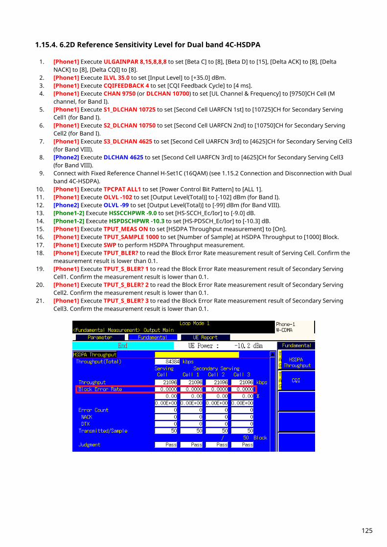
1.15.4. 6.2D Reference Sensitivity Level for Dual band 4C-HSDPA
1. [Phone1] Execute ULGAINPAR 8,15,8,8,8 to set [Beta C] to [8], [Beta D] to [15], [Delta ACK] to [8], [Delta NACK] to [8], [Delta CQI] to [8].
2. [Phone1] Execute ILVL 35.0 to set [Input Level] to [+35.0] dBm. 3. [Phone1] Execute CQIFEEDBACK 4 to set [CQI Feedback Cycle] to [4 ms]. 4. [Phone1] Execute CHAN 9750 (or DLCHAN 10700) to set [UL Channel & Frequency] to [9750]CH Cell (M
channel, for Band I). 5. [Phone1] Execute S1_DLCHAN 10725 to set [Second Cell UARFCN 1st] to [10725]CH for Secondary Serving
Cell1 (for Band I). 6. [Phone1] Execute S2_DLCHAN 10750 to set [Second Cell UARFCN 2nd] to [10750]CH for Secondary Serving
Cell2 (for Band I). 7. [Phone1] Execute S3_DLCHAN 4625 to set [Second Cell UARFCN 3rd] to [4625]CH for Secondary Serving Cell3
(for Band VIII). 8. [Phone2] Execute DLCHAN 4625 to set [Second Cell UARFCN 3rd] to [4625]CH for Secondary Serving Cell3
(for Band VIII). 9. Connect with Fixed Reference Channel H-Set1C (16QAM) (see 1.15.2 Connection and Disconnection with Dual
band 4C-HSDPA). 10. [Phone1] Execute TPCPAT ALL1 to set [Power Control Bit Pattern] to [ALL 1]. 11. [Phone1] Execute OLVL -102 to set [Output Level(Total)] to [-102] dBm (for Band I). 12. [Phone2] Execute OLVL -99 to set [Output Level(Total)] to [-99] dBm (for Band VIII). 13. [Phone1-2] Execute HSSCCHPWR -9.0 to set [HS-SCCH_Ec/Ior] to [-9.0] dB. 14. [Phone1-2] Execute HSPDSCHPWR -10.3 to set [HS-PDSCH_Ec/Ior] to [-10.3] dB. 15. [Phone1] Execute TPUT_MEAS ON to set [HSDPA Throughput measurement] to [On]. 16. [Phone1] Execute TPUT_SAMPLE 1000 to set [Number of Sample] at HSDPA Throughput to [1000] Block. 17. [Phone1] Execute SWP to perform HSDPA Throughput measurement. 18. [Phone1] Execute TPUT_BLER? to read the Block Error Rate measurement result of Serving Cell. Confirm the
measurement result is lower than 0.1. 19. [Phone1] Execute TPUT_S_BLER? 1 to read the Block Error Rate measurement result of Secondary Serving
Cell1. Confirm the measurement result is lower than 0.1. 20. [Phone1] Execute TPUT_S_BLER? 2 to read the Block Error Rate measurement result of Secondary Serving
Cell2. Confirm the measurement result is lower than 0.1. 21. [Phone1] Execute TPUT_S_BLER? 3 to read the Block Error Rate measurement result of Secondary Serving
Cell3. Confirm the measurement result is lower than 0.1.
125
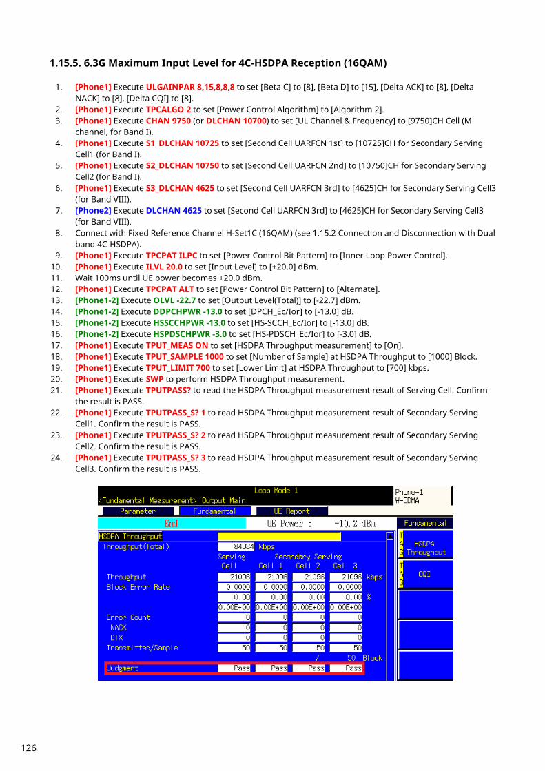
1.15.5. 6.3G Maximum Input Level for 4C-HSDPA Reception (16QAM)
1. [Phone1] Execute ULGAINPAR 8,15,8,8,8 to set [Beta C] to [8], [Beta D] to [15], [Delta ACK] to [8], [Delta NACK] to [8], [Delta CQI] to [8].
2. [Phone1] Execute TPCALGO 2 to set [Power Control Algorithm] to [Algorithm 2]. 3. [Phone1] Execute CHAN 9750 (or DLCHAN 10700) to set [UL Channel & Frequency] to [9750]CH Cell (M
channel, for Band I). 4. [Phone1] Execute S1_DLCHAN 10725 to set [Second Cell UARFCN 1st] to [10725]CH for Secondary Serving
Cell1 (for Band I). 5. [Phone1] Execute S2_DLCHAN 10750 to set [Second Cell UARFCN 2nd] to [10750]CH for Secondary Serving
Cell2 (for Band I). 6. [Phone1] Execute S3_DLCHAN 4625 to set [Second Cell UARFCN 3rd] to [4625]CH for Secondary Serving Cell3
(for Band VIII). 7. [Phone2] Execute DLCHAN 4625 to set [Second Cell UARFCN 3rd] to [4625]CH for Secondary Serving Cell3
(for Band VIII). 8. Connect with Fixed Reference Channel H-Set1C (16QAM) (see 1.15.2 Connection and Disconnection with Dual
band 4C-HSDPA). 9. [Phone1] Execute TPCPAT ILPC to set [Power Control Bit Pattern] to [Inner Loop Power Control].
10. [Phone1] Execute ILVL 20.0 to set [Input Level] to [+20.0] dBm. 11. Wait 100ms until UE power becomes +20.0 dBm. 12. [Phone1] Execute TPCPAT ALT to set [Power Control Bit Pattern] to [Alternate]. 13. [Phone1-2] Execute OLVL -22.7 to set [Output Level(Total)] to [-22.7] dBm. 14. [Phone1-2] Execute DDPCHPWR -13.0 to set [DPCH_Ec/Ior] to [-13.0] dB. 15. [Phone1-2] Execute HSSCCHPWR -13.0 to set [HS-SCCH_Ec/Ior] to [-13.0] dB. 16. [Phone1-2] Execute HSPDSCHPWR -3.0 to set [HS-PDSCH_Ec/Ior] to [-3.0] dB. 17. [Phone1] Execute TPUT_MEAS ON to set [HSDPA Throughput measurement] to [On]. 18. [Phone1] Execute TPUT_SAMPLE 1000 to set [Number of Sample] at HSDPA Throughput to [1000] Block. 19. [Phone1] Execute TPUT_LIMIT 700 to set [Lower Limit] at HSDPA Throughput to [700] kbps. 20. [Phone1] Execute SWP to perform HSDPA Throughput measurement. 21. [Phone1] Execute TPUTPASS? to read the HSDPA Throughput measurement result of Serving Cell. Confirm
the result is PASS. 22. [Phone1] Execute TPUTPASS_S? 1 to read HSDPA Throughput measurement result of Secondary Serving
Cell1. Confirm the result is PASS. 23. [Phone1] Execute TPUTPASS_S? 2 to read HSDPA Throughput measurement result of Secondary Serving
Cell2. Confirm the result is PASS. 24. [Phone1] Execute TPUTPASS_S? 3 to read HSDPA Throughput measurement result of Secondary Serving
Cell3. Confirm the result is PASS.
126
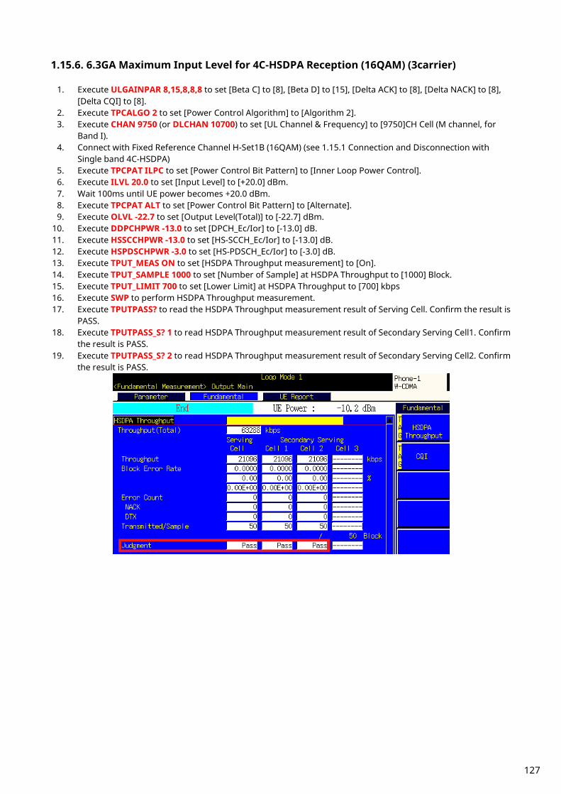
1.15.6. 6.3GA Maximum Input Level for 4C-HSDPA Reception (16QAM) (3carrier)
1. Execute ULGAINPAR 8,15,8,8,8 to set [Beta C] to [8], [Beta D] to [15], [Delta ACK] to [8], [Delta NACK] to [8], [Delta CQI] to [8].
2. Execute TPCALGO 2 to set [Power Control Algorithm] to [Algorithm 2]. 3. Execute CHAN 9750 (or DLCHAN 10700) to set [UL Channel & Frequency] to [9750]CH Cell (M channel, for
Band I). 4. Connect with Fixed Reference Channel H-Set1B (16QAM) (see 1.15.1 Connection and Disconnection with
Single band 4C-HSDPA) 5. Execute TPCPAT ILPC to set [Power Control Bit Pattern] to [Inner Loop Power Control]. 6. Execute ILVL 20.0 to set [Input Level] to [+20.0] dBm. 7. Wait 100ms until UE power becomes +20.0 dBm. 8. Execute TPCPAT ALT to set [Power Control Bit Pattern] to [Alternate]. 9. Execute OLVL -22.7 to set [Output Level(Total)] to [-22.7] dBm.
10. Execute DDPCHPWR -13.0 to set [DPCH_Ec/Ior] to [-13.0] dB. 11. Execute HSSCCHPWR -13.0 to set [HS-SCCH_Ec/Ior] to [-13.0] dB. 12. Execute HSPDSCHPWR -3.0 to set [HS-PDSCH_Ec/Ior] to [-3.0] dB. 13. Execute TPUT_MEAS ON to set [HSDPA Throughput measurement] to [On]. 14. Execute TPUT_SAMPLE 1000 to set [Number of Sample] at HSDPA Throughput to [1000] Block. 15. Execute TPUT_LIMIT 700 to set [Lower Limit] at HSDPA Throughput to [700] kbps 16. Execute SWP to perform HSDPA Throughput measurement. 17. Execute TPUTPASS? to read the HSDPA Throughput measurement result of Serving Cell. Confirm the result is
PASS. 18. Execute TPUTPASS_S? 1 to read HSDPA Throughput measurement result of Secondary Serving Cell1. Confirm
the result is PASS. 19. Execute TPUTPASS_S? 2 to read HSDPA Throughput measurement result of Secondary Serving Cell2. Confirm
the result is PASS.
127
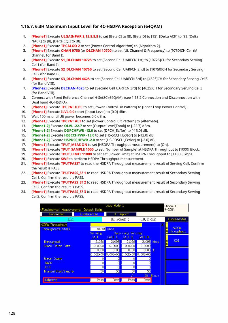
1.15.7. 6.3H Maximum Input Level for 4C-HSDPA Reception (64QAM)
1. [Phone1] Execute ULGAINPAR 8,15,8,8,8 to set [Beta C] to [8], [Beta D] to [15], [Delta ACK] to [8], [Delta NACK] to [8], [Delta CQI] to [8].
2. [Phone1] Execute TPCALGO 2 to set [Power Control Algorithm] to [Algorithm 2]. 3. [Phone1] Execute CHAN 9750 (or DLCHAN 10700) to set [UL Channel & Frequency] to [9750]CH Cell (M
channel, for Band I). 4. [Phone1] Execute S1_DLCHAN 10725 to set [Second Cell UARFCN 1st] to [10725]CH for Secondary Serving
Cell1 (for Band I). 5. [Phone1] Execute S2_DLCHAN 10750 to set [Second Cell UARFCN 2nd] to [10750]CH for Secondary Serving
Cell2 (for Band I). 6. [Phone1] Execute S3_DLCHAN 4625 to set [Second Cell UARFCN 3rd] to [4625]CH for Secondary Serving Cell3
(for Band VIII). 7. [Phone2] Execute DLCHAN 4625 to set [Second Cell UARFCN 3rd] to [4625]CH for Secondary Serving Cell3
(for Band VIII). 8. Connect with Fixed Reference Channel H-Set8C (64QAM). (see 1.15.2 Connection and Disconnection with
Dual band 4C-HSDPA). 9. [Phone1] Execute TPCPAT ILPC to set [Power Control Bit Pattern] to [Inner Loop Power Control].
10. [Phone1] Execute ILVL 0.0 to set [Input Level] to [0.0] dBm. 11. Wait 100ms until UE power becomes 0.0 dBm. 12. [Phone1] Execute TPCPAT ALT to set [Power Control Bit Pattern] to [Alternate]. 13. [Phone1-2] Execute OLVL -22.7 to set [Output Level(Total)] to [-22.7] dBm. 14. [Phone1-2] Execute DDPCHPWR -13.0 to set [DPCH_Ec/Ior] to [-13.0] dB. 15. [Phone1-2] Execute HSSCCHPWR -13.0 to set [HS-SCCH_Ec/Ior] to [-13.0] dB. 16. [Phone1-2] Execute HSPDSCHPWR -2.0 to set [HS-PDSCH_Ec/Ior] to [-2.0] dB. 17. [Phone1] Execute TPUT_MEAS ON to set [HSDPA Throughput measurement] to [On]. 18. [Phone1] Execute TPUT_SAMPLE 1000 to set [Number of Sample] at HSDPA Throughput to [1000] Block. 19. [Phone1] Execute TPUT_LIMIT 11800 to set set [Lower Limit] at HSDPA Throughput to [11800] kbps. 20. [Phone1] Execute SWP to perform HSDPA Throughput measurement. 21. [Phone1] Execute TPUTPASS? to read the HSDPA Throughput measurement result of Serving Cell. Confirm
the result is PASS. 22. [Phone1] Execute TPUTPASS_S? 1 to read HSDPA Throughput measurement result of Secondary Serving
Cell1. Confirm the result is PASS. 23. [Phone1] Execute TPUTPASS_S? 2 to read HSDPA Throughput measurement result of Secondary Serving
Cell2. Confirm the result is PASS. 24. [Phone1] Execute TPUTPASS_S? 3 to read HSDPA Throughput measurement result of Secondary Serving
Cell3. Confirm the result is PASS.
128
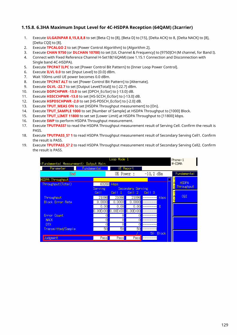
1.15.8. 6.3HA Maximum Input Level for 4C-HSDPA Reception (64QAM) (3carrier)
1. Execute ULGAINPAR 8,15,8,8,8 to set [Beta C] to [8], [Beta D] to [15], [Delta ACK] to 8, [Delta NACK] to [8], [Delta CQI] to [8].
2. Execute TPCALGO 2 to set [Power Control Algorithm] to [Algorithm 2]. 3. Execute CHAN 9750 (or DLCHAN 10700) to set [UL Channel & Frequency] to [9750]CH (M channel, for Band I). 4. Connect with Fixed Reference Channel H-Set1B(16QAM) (see 1.15.1 Connection and Disconnection with
Single band 4C-HSDPA). 5. Execute TPCPAT ILPC to set [Power Control Bit Pattern] to [Inner Loop Power Control]. 6. Execute ILVL 0.0 to set [Input Level] to [0.0] dBm. 7. Wait 100ms until UE power becomes 0.0 dBm. 8. Execute TPCPAT ALT to set [Power Control Bit Pattern] to [Alternate]. 9. Execute OLVL -22.7 to set [Output Level(Total)] to [-22.7] dBm.
10. Execute DDPCHPWR -13.0 to set [DPCH_Ec/Ior] to [-13.0] dB. 11. Execute HSSCCHPWR -13.0 to set [HS-SCCH_Ec/Ior] to [-13.0] dB. 12. Execute HSPDSCHPWR -2.0 to set [HS-PDSCH_Ec/Ior] to [-2.0] dB. 13. Execute TPUT_MEAS ON to set [HSDPA Throughput measurement] to [On]. 14. Execute TPUT_SAMPLE 1000 to set [Number of Sample] at HSDPA Throughput to [1000] Block. 15. Execute TPUT_LIMIT 11800 to set set [Lower Limit] at HSDPA Throughput to [11800] kbps. 16. Execute SWP to perform HSDPA Throughput measurement. 17. Execute TPUTPASS? to read the HSDPA Throughput measurement result of Serving Cell. Confirm the result is
PASS. 18. Execute TPUTPASS_S? 1 to read HSDPA Throughput measurement result of Secondary Serving Cell1. Confirm
the result is PASS. 19. Execute TPUTPASS_S? 2 to read HSDPA Throughput measurement result of Secondary Serving Cell2. Confirm
the result is PASS.
129
1.16. DC-HSUPA Measurement *This chapter describes measurements when Phone1 and Phone 2 are used as Serving Cell and Secondary Serving Cell, respectively for DC-HSUPA connection.
1.16.1. Synchronization of Frame Timing between 2 cells Synchronizing frame timing between 2 cells is required when connecting with DC-HSDPA.
1. [Phone1] Execute ENTERSYNC IN_SLAVE to be slave condition of frame timing synchronization. 2. [Phone2] Execute ENTERSYNC MASTER to perform frame timing synchronization. 3. [Phone1] Execute ENTERSYNC? to check response becomes 1 (synchronized).
1.16.2. Location Registration for DC-HSUPA Location registration with Combined is required when connecting with DC-HSUPA.
1. [Phone1-2] Execute PRESET_3GPP to preset parameters for 3GPP. 2. [Phone1] Execute CHCODING EDCHTEST_DC to set [Channel Coding] to [E-DCH RF Test for DC-HSUPA]. 3. [Phone1] Execute INTEGRITY ON to set [Integrity Protection] to [On]. 4. [Phone1] Execute REGMODE COMBINED to set [Registration Mode] to [Combined]. 5. [Phone2] Execute CHCODING EDCHTEST_DC to set [Channel Coding] to [EDCH RF Test for DC-HSUPA]. 6. [Phone2] Execute LVL OFF to set [Output Level Total)] to [Off] for Secondary Serving Cell. 7. [Phone2] Execute CALLPROC OFF to set [Call Processing] of Secondary Serving Cell to [Off] to output each
channel. 8. Turn on the UE power. 9. [Phone1] Execute CALLSTAT? and wait until the response becomes 2 (= Idle (Regist)).
1.16.3. Connection with DC-HSUPA(QPSK) The process after location registration is shown below. (see 1.15.2 Location Registration for DC-HSUPA.)
1. [Phone1] Execute DCHSUSET TTI2_QPSK to set [DC-HSUPA Set of Parameters] to [TTI 2ms(QPSK)]. 2. [Phone1] Execute S_DLCHAN 10725 to set [Second Cell UARFCN] to [10725]CH for Secondary Serving Cell
(when the DL channel of Serving Cell is 10700). 3. [Phone1] Execute DPCCHPWROFS -80 to set DPCCH Power Offset Level to [-80] dB. 4. [Phone1] Execute DELTA_ACK 0 to set [Delta ACK] to [0]. 5. [Phone1] Execute DELTA_NACK 0 to set [Delta NACK] to [0]. 6. [Phone1] Execute DELTA_CQI 0 to set [Delta CQI] to [0]. 7. [Phone1] Execute DELTA_EC 0 to set [Delta E-DPCCH] to [0]. 8. [Phone1] Execute MINSET_ETFCI 67 to set [E-DCH minimum set of E-TFCI] to [67]. 9. [Phone1] Execute ALLREFETFCI 2,1,12,68,19 to set [Number of E-TFCIs] to [2],[Reference E-TFCI] to [1,68],
[Reference E-TFCI PO] to [12,19]. 10. [Phone1] Execute CALLSA to connect with DC-HSDPA+DC-HSUPA. 11. [Phone1] Execute CALLSTAT? and wait until the response becomes 7 (=Test Loop Mode). 12. [Phone2] Execute DCHSUSET TTI2_QPSK to set [DC-HSUPA Set of Parameters] to [TTI 2ms(QPSK)]. 13. [Phone2] Execute DCHSUCELL SEC to set [DC-HSUPA Set of Parameters-Serving Cell Type] to [Secondary]. 14. [Phone2] Execute DLCHAN 10725 to set [DL Channel & Frequency] to [10725]CH for Secondary Serving Cell. 15. [Phone2] Execute EAGCHCODE 10 to set [E-AGCH Channelization Code] to [10]. 16. [Phone2] Execute EHICHCODE 4 to set [E-HICH Channelization Code] to [4]. 17. [Phone2] Execute LVL ON to set [Output Level(Total)] to [On] for Secondary Serving Cell.
130

1.16.4. Connection with DC-HSUPA(16QAM) The process after location registration is shown below. (See 1.15.2 Location Registration for DC-HSUPA.)
1. [Phone1] Execute DCHSUSET TTI2_16QAM to set [DC-HSUPA Set of Parameters] to [TTI 2ms(16QAM)]. 2. [Phone1] Execute S_DLCHAN 10725 to set [Second Cell UARFCN] to [10725]CH for Secondary Serving Cell
(when the DL channel of Serving Cell is 10700). 3. [Phone1] Execute DPCCHPWROFS -80 to set DPCCH Power Offset Level to [-80] dB. 4. [Phone1] Execute DELTA_ACK 6 to set [Delta ACK] to [6]. 5. [Phone1] Execute DELTA_NACK 6 to set [Delta NACK] to [6]. 6. [Phone1] Execute DELTA_CQI 6to set [Delta CQI] to [6]. 7. [Phone1] Execute DELTA_EC 0 to set [Delta E-DPCCH] to [0]. 8. [Phone1] Execute MINSET_ETFCI 67 to set [E-DCH minimum set of E-TFCI] to [67]. 9. [Phone1] Execute ALLREFETFCI 2,1,12,68,19 to set [Number of E-TFCIs] to [2],[Reference E-TFCI] to [1,68],
[Reference E-TFCI PO] to [12,19]. 10. [Phone1] Execute CALLSA to connect with DC-HSDPA+DC-HSUPA. 11. [Phone1] Execute CALLSTAT? and wait until the response becomes 7 (=Test Loop Mode). 12. [Phone2] Execute DCHSUSET TTI2_16QAM to set [DC-HSUPA Set of Parameters] to [TTI 2ms(16QAM)]. 13. [Phone2] Execute DCHSUCELL SEC to set [DC-HSUPA Set of Parameters-Serving Cell Type] to [Secondary]. 14. [Phone2] Execute DLCHAN 10725 to set [DL Channel & Frequency] to [10725]CH for Secondary Serving Cell. 15. [Phone2] Execute EAGCHCODE 10 to set [E-AGCH Channelization Code] to [10]. 16. [Phone2] Execute EHICHCODE 4 to set [E-HICH Channelization Code] to [4]. 17. [Phone2] Execute LVL ON to set [Output Level(Total)] to [On] for Secondary Serving Cell.
1.16.5. Disconnection with DC-HSUPA
1. [Phone2] Execute HSSCCH OFF to set [HSSCCH power] to [Off] for Secondary Serving Cell. 2. [Phone1] Execute CALLSO to disconnect with DC-HSUPA (by pressing “End Call” key). 3. [Phone1] Execute CALLSTAT? and wait until the response becomes 2 (=Idle(Regist)).
1.16.6. Channel Switching using Handover Usually, measurement is performed at three frequency points (L, M, H). In this case, the Channel can be switched quickly without reconnection by switching it at handover with a higher output level and Beta C for UL DPCCH. When a GPIB command is sent during handover, it waits until handover ends.
1. [Phone2] Execute HSSCCH OFF to set [HSSCCH power] to [Off] for Secondary Serving Cell. 2. [Phone1] Execute RX measurement with M channel. 3. [Phone1] Execute S_DLCHAN 10588 to set [Second Cell UARFCN] to [10588]CH for Secondary Serving Cell. 4. [Phone1] Execute CHAN 9613 (or DLCHAN 10563) to set [UL Channel & Frequency] to [9613]CH and perform
handover to L channel. 5. [Phone2] Execute DLCHAN 10588 to set [DL Channel & Frequency] to [10588]CH for Secondary Serving Cell. 6. [Phone1] Execute RX measurement. 7. [Phone1] Execute S_DLCHAN 10812 to set [Second Cell UARFCN] to [10812]CH for Secondary Serving Cell. 8. [Phone1] Execute CHAN 9887 (or DLCHAN 10837) to set [UL Channel & Frequency] to [9887]CH and perform
handover to handover to H channel. 9. [Phone2] Execute DLCHAN 10812 to set [DL Channel & Frequency] to [10812]CH for Secondary Serving Cell.
10. [Phone2] Execute HSSCCH ON to set [HSSCCH power] to [On] for Secondary Serving Cell. 11. [Phone1] Execute RX measurement.
131

1.16.7. Measurement Item Selection For DC-HSUPA Measurement, Phone1 and Phone 2 are used as Serving Cell and Secondary Serving Cell, respectively for DC-HSUPA connection. Phone1 and 2 have different measurement methods as follows. (These differences depend on the parameter setting of “DC-HSUPA Set of Parameters – Serving Cell Type”.)
MT8820C Fundamental Measurement specification table of "E-DCH RF Test for DC-HSDUPA" Fundamental Measurement
Items
DC-HSUPA Set of Parameters - Serving Cell Type
Primary Cell(Phone1) Secondary Cell(Phone2)
Power Measurement Primary&Secondary Secondary(*2)
Frequency Error Primary Secondary
Occupied Bandwidth(*1) Primary&Secondary -
Spectrum Emission
Mask(*1) Primary&Secondary -
Adjacent Channel
Power(*1) Primary&Secondary -
Modulation Analysis Primary Secondary
Peak Code Domain Error Primary Secondary
Relative Code Domain Error Primary Secondary
Bit Error Rate - -
Block Error Rate - -
HSDPA Throughput Primary&Secondary -
CQI Primary&Secondary -
HSUPA Throughput Primary Secondary "Primary": MT8820C measures UE as Serving Cell. "Secondary": MT8820C measures UE as Secondary Serving Cell . "Primary+Secondary": MT8820C measures UE as Serving Cell/Secondary Serving Cell at the same time. "-": Measurement result is not valid. (*1) To measure these items, other items should be turned off.
For example, Power Measurement and Spectrum Emission Mask cannot be measured at the same time. (*2) Measurement results are displayed on the Primary results area.
The MT8820/15B is set for W-CDMA measurement at preset. Since DC-HSUPA Throughput measurement items are set to off, turn on these items to measure (TPUTU_MEAS ON). Although BER measurement and BLER measurement are unnecessary items, turn off these items to cut the
measurement time (BER_MEAS OFF, BLER_MEAS OFF).
132

1.16.8. 5.2BA UE Maximum Output Power for DC-HSUPA(QPSK)
1. [Phone1]Execute DDPCHTOFS 6 to set [DPCH Timing Offset] to [6]. 2. [Phone1]Execute MAXULPWR 21 to set [Maximum Allowed UL TX Power] to [21.0] dBm. 3. [Phone1]Execute TPCALGO 1 to set [TPC Algorithm] to [1]. 4. [Phone1]Connect with DC-HSUPA(QPSK). 5. [Phone1]Execute OLVL -86.0 to set [Output Level] to [-86.0dBm]. 6. [Phone1]Execute OBW_MEAS OFF to set [Occupied Bandwidth measurement] to [Off]. 7. [Phone1]Execute SMASK_MEAS OFF to set [Spectrum Emission Mask measurement] to [Off]. 8. [Phone1]Execute ADJ_MEAS OFF to set [Adjacent Channel Power measurement] to [Off]. 9. [Phone1]Execute PWR_MEAS ON to set [Power measurement] to [On].
10. [Phone1]Execute PWR_AVG 20 to set [Average Count] of Power measurement to [20] times. 11. [Phone1]Execute EHICHPAT ACK to set [E-HICH Pattern] to [ACK]. 12. [Phone1]Execute ABSGNTVAL 6 to set [Absolute Grant Value] to [6]. 13. [Phone2]Execute DDPCHTOFS 6 to set [DPCH Timing Offset] to [6]. 14. [Phone2]Execute OLVL -86.0 to set [Output Level] to [-86.0dBm]. 15. [Phone2]Execute EHICHPAT ACK to set [E-HICH Pattern] to [ACK]. 16. [Phone2]Execute ABSGNTVAL 6 to set [Absolute Grant Value] to [6]. 17. [Phone1]Execute TPCPAT ILPC to set [Power Control Bit Pattern] to [Inner Loop Power Control]. 18. [Phone1]Execute ILVL 10.0 to set [Input Level] to [+10.0] dBm. 19. [Phone2]Execute ILVL 10.0 to set [Input Level] to [+10.0] dBm. 20. Wait 150ms until the UE power becomes 10.0 dBm. 21. [Phone1]Execute ILVL 35.0 to set [Input Level] to [+35.0] dBm. 22. [Phone2]Execute ILVL 35.0 to set [Input Level] to [+35.0] dBm. 23. [Phone1]Execute TPCPAT ALL1 to set [Power Control Bit Pattern] to [All1]. 24. [Phone2]Execute TPCPAT ALL1 to set [Power Control Bit Pattern] to [All1]. 25. Wait 150ms until the UE power reaches Maximum Power. 26. [Phone1]Execute SWP to perform Power measurement. 27. [Phone1]Execute AVG_POWER? to read the Power measurement result as Power1. 28. [Phone1]Execute AVG_POWER_S? to read the Power measurement result as Power2.
Confirm the measurement result (above Power1+Power2) is +22.5 dBm (Tolerance +3.2/–4.7) To measure Power, OBW,SEM and ACLR measurement items should be turned off.
1.16.9. 5.2BB UE Maximum Output Power for DC-HSUPA(16QAM)
1. [Phone1]Execute DDPCHTOFS 6 to set [DPCH Timing Offset] to [6]. 2. [Phone1]Execute MAXULPWR 21 to set [Maximum Allowed UL TX Power] to [21.0] dBm. 3. [Phone1]Execute TPCALGO 1 to set [TPC Algorithm] to [1]. 4. [Phone1]Connect with DC-HSUPA(16QAM). 5. [Phone1]Execute OLVL -86.0 to set [Output Level] to [-86.0dBm]. 6. [Phone1]Execute OBW_MEAS OFF to set [Occupied Bandwidth measurement] to [Off]. 7. [Phone1]Execute SMASK_MEAS OFF to set [Spectrum Emission Mask measurement] to [Off]. 8. [Phone1]Execute ADJ_MEAS OFF to set [Adjacent Channel Power measurement] to [Off]. 9. [Phone1]Execute PWR_MEAS ON to set [Power measurement] to [On].
10. [Phone1]Execute PWR_AVG 20 to set [Average Count] of Power measurement to [20] times. 11. [Phone1]Execute EHICHPAT ACK to set [E-HICH Pattern] to [ACK]. 12. [Phone1]Execute ABSGNTVAL 24 to set [Absolute Grant Value] to [24]. 13. [Phone2]Execute DDPCHTOFS 6 to set [DPCH Timing Offset] to [6]. 14. [Phone2]Execute OLVL -86.0 to set [Output Level] to [-86.0dBm]. 15. [Phone2]Execute EHICHPAT ACK to set [E-HICH Pattern] to [ACK]. 16. [Phone2]Execute ABSGNTVAL 24 to set [Absolute Grant Value] to [24]. 17. [Phone1]Execute TPCPAT ILPC to set [Power Control Bit Pattern] to [Inner Loop Power Control]. 18. [Phone1]Execute ILVL 10.0 to set [Input Level] to [+10.0] dBm. 19. [Phone2]Execute ILVL 10.0 to set [Input Level] to [+10.0] dBm. 20. Wait 150ms until the UE power becomes 10.0 dBm. 21. [Phone1]Execute ILVL 35.0 to set [Input Level] to [+35.0] dBm. 22. [Phone2]Execute ILVL 35.0 to set [Input Level] to [+35.0] dBm. 23. [Phone1]Execute TPCPAT ALL1 to set [Power Control Bit Pattern] to [All1].
133
24. [Phone2]Execute TPCPAT ALL1 to set [Power Control Bit Pattern] to [All1]. 25. Wait 150ms until the UE power reaches Maximum Power. 26. [Phone1]Execute SWP to perform Power measurement. 27. [Phone1]Execute AVG_POWER? to read the Power measurement result as Power1. 28. [Phone1]Execute AVG_POWER_S? to read the Power measurement result as Power2.
Confirm the measurement result (above Power1+Power2) is +22.5 dBm (Tolerance +3.2/–4.7) To measure Power, OBW, SEM and ACLR measurement items should be turned off.
1.16.10. 5.2DA UE Relative Code Domain Power Accuracy for DC-HSUPA with QPSK
1. [Phone1]Execute DDPCHTOFS 6 to set [DPCH Timing Offset] to [6]. 2. [Phone1]Execute MAXULPWR 21 to set [Maximum Allowed UL TX Power] to [21.0] dBm. 3. [Phone1]Execute TPCALGO 2 to set [TPC Algorithm] to [2]. 4. [Phone1]Connect with DC-HSUPA(QPSK). 5. [Phone1]Execute OLVL -86.0 to set [Output Level] to [-86.0dBm]. 6. [Phone1]Execute OBW_MEAS OFF to set [Occupied Bandwidth measurement] to [Off]. 7. [Phone1]Execute SMASK_MEAS OFF to set [Spectrum Emission Mask measurement] to [Off]. 8. [Phone1]Execute ADJ_MEAS OFF to set [Adjacent Channel Power measurement] to [Off]. 9. [Phone1]Execute TPUTU_MEAS ON to set [HSUPA Throughput] measurement to [On].
10. [Phone1]Execute TPUTU_SAMPLE 15 to set [HSUPA Throughput - Number of Sample] to [15]. 11. [Phone1]Execute EHICHPAT ACK to set [E-HICH Pattern] to [ACK]. 12. [Phone1]Execute ABSGNTVAL 6 to set [Absolute Grant Value] to [6]. 13. [Phone2]Execute DDPCHTOFS 6 to set [DPCH Timing Offset] to [6]. 14. [Phone2]Execute OLVL -86.0 to set [Output Level] to [-86.0dBm]. 15. [Phone2]Execute OBW_MEAS OFF to set [Occupied Bandwidth measurement] to [Off]. 16. [Phone2]Execute SMASK_MEAS OFF to set [Spectrum Emission Mask measurement] to [Off]. 17. [Phone2]Execute ADJ_MEAS OFF to set [Adjacent Channel Power measurement] to [Off]. 18. [Phone2]Execute PWR_MEAS ON to set [Power measurement] to [On]. 19. [Phone2]Execute PWR_AVG 20 to set [Average Count] of Power measurement to [20] times. 20. [Phone2]Execute TPUTU_MEAS ON to set [HSUPA Throughput] measurement to [On]. 21. [Phone2]Execute TPUTU_SAMPLE 15 to set [HSUPA Throughput - Number of Sample] to [15]. 22. [Phone2]Execute EHICHPAT ACK to set [E-HICH Pattern] to [ACK]. 23. [Phone2]Execute ABSGNTVAL 6 to set [Absolute Grant Value] to [6]. 24. [Phone1]Execute SCRSEL FMEAS to display the Fundamental Measurement screen. 25. [Phone1]Execute TPCPAT ILPC to set [Power Control Bit Pattern] to [Inner Loop Power Control]. 26. [Phone2]Execute SCRSEL FMEAS to display the Fundamental Measurement screen. 27. [Phone2]Execute TPCPAT ILPC to set [Power Control Bit Pattern] to [Inner Loop Power Control]. 28. [Phone1]Execute ILVL 15.0 to set [Input Level] to [+15.0] dBm. 29. [Phone2]Execute ILVL 15.0 to set [Input Level] to [+15.0] dBm. 30. Wait 150ms until the UE power becomes 15.0 dBm. 31. [Phone1]Execute TPCPAT ALT to set [Power Control Bit Pattern] to [Alternate]. 32. [Phone1]Execute SWP to perform HSUPA Throughput measurement. 33. [Phone1]Execute AVG_ETFCI? to read the E-TFCI measurement result, and confirm it is 1. 34. [Phone2]Execute TPCPAT ALT to set [Power Control Bit Pattern] to [Alternate]. 35. [Phone2]Execute SWP to perform HSUPA Throughput measurement. 36. [Phone2]Execute AVG_ETFCI? to read the E-TFCI measurement result, and confirm it is 1. 37. [Phone1]Execute SCRSEL TDMEAS to display the Time Domain Measurement screen. 38. [Phone1]Execute MEASOBJ HSDPCCH_MA to set [Measurement Object] to [HS-DPCCH Modulation Analysis]. 39. [Phone1]Execute HSMA_ITEM CDP to set measurement result of HS-DPCCH (Modulation Analysis) to [CDP
Ratio]. 40. [Phone1]Execute SWP to perform CDP Ratio measurement. 41. [Phone1]Confirm the measurement results of Relative Code Domain Power are as follows.
DPCCH -5.8dB(Accuracy +/-1.7), HS-DPCCH -15.3(Accuracy +/-2.9), E-DPCCH -15.3(Accuracy +/-2.9), E-DPDCH -1.7(Accuracy +/-1.7)
42. [Phone2]Execute SCRSEL TDMEAS to display the Time Domain Measurement screen. 43. [Phone2]Execute MEASOBJ HSDPCCH_MA to set [Measurement Object] to [HS-DPCCH Modulation Analysis]. 44. [Phone2]Execute HSMA_ITEM CDP to set measurement result of HS-DPCCH (Modulation Analysis) to [CDP
Ratio].
134

45. [Phone2]Execute SWP to perform CDP Ratio measurement. 46. [Phone2]Confirm the measurement results of Relative Code Domain Power are as follows.
DPCCH -5.6dB(Accuracy +/-1.7), E-DPCCH -15.2(Accuracy +/-2.9), E-DPDCH -1.6(Accuracy +/-1.7)
To measure Power/ HSUPA Throughput, OBW,SEM and ACLR measurement items should be turned off.
1.16.11. 5.2EA UE Relative Code Domain Power Accuracy for DC-HSUPA with 16QAM
1. [Phone1]Execute DDPCHTOFS 6 to set [DPCH Timing Offset] to [6]. 2. [Phone1]Execute MAXULPWR 21 to set [Maximum Allowed UL TX Power] to [21.0] dBm. 3. [Phone1]Execute TPCALGO 2 to set [TPC Algorithm] to [2]. 4. [Phone1]Connect with DC-HSUPA(16QAM). 5. [Phone1]Execute OLVL -86.0 to set [Output Level] to [-86.0dBm]. 6. [Phone1]Execute OBW_MEAS OFF to set [Occupied Bandwidth measurement] to [Off]. 7. [Phone1]Execute SMASK_MEAS OFF to set [Spectrum Emission Mask measurement] to [Off]. 8. [Phone1]Execute ADJ_MEAS OFF to set [Adjacent Channel Power measurement] to [Off]. 9. [Phone1]Execute TPUTU_MEAS ON to set [HSUPA Throughput] measurement to [On].
10. [Phone1]Execute TPUTU_SAMPLE 15 to set [HSUPA Throughput - Number of Sample] to [15]. 11. [Phone1]Execute EHICHPAT ACK to set [E-HICH Pattern] to [ACK]. 12. [Phone1]Execute ABSGNTVAL 24 to set [Absolute Grant Value] to [24]. 13. [Phone2]Execute DDPCHTOFS 6 to set [DPCH Timing Offset] to [6]. 14. [Phone2]Execute OLVL -86.0 to set [Output Level] to [-86.0dBm]. 15. [Phone2]Execute OBW_MEAS OFF to set [Occupied Bandwidth measurement] to [Off]. 16. [Phone2]Execute SMASK_MEAS OFF to set [Spectrum Emission Mask measurement] to [Off]. 17. [Phone2]Execute ADJ_MEAS OFF to set [Adjacent Channel Power measurement] to [Off]. 18. [Phone2]Execute PWR_MEAS ON to set [Power measurement] to [On]. 19. [Phone2]Execute PWR_AVG 20 to set [Average Count] of Power measurement to [20] times. 20. [Phone2]Execute TPUTU_MEAS ON to set [HSUPA Throughput] measurement to [On]. 21. [Phone2]Execute TPUTU_SAMPLE 15 to set [HSUPA Throughput - Number of Sample] to [15]. 22. [Phone2]Execute EHICHPAT ACK to set [E-HICH Pattern] to [ACK]. 23. [Phone2]Execute ABSGNTVAL 24 to set [Absolute Grant Value] to [24]. 24. [Phone1]Execute SCRSEL FMEAS to display the Fundamental Measurement screen. 25. [Phone1]Execute TPCPAT ILPC to set [Power Control Bit Pattern] to [Inner Loop Power Control]. 26. [Phone2]Execute SCRSEL FMEAS to display the Fundamental Measurement screen. 27. [Phone2]Execute TPCPAT ILPC to set [Power Control Bit Pattern] to [Inner Loop Power Control]. 28. [Phone1]Execute ILVL 15.0 to set [Input Level] to [+15.0] dBm. 29. [Phone2]Execute ILVL 15.0 to set [Input Level] to [+15.0] dBm. 30. Wait 150ms until the UE power becomes 15.0 dBm. 31. [Phone1]Execute TPCPAT ALT to set [Power Control Bit Pattern] to [Alternate]. 32. [Phone1]Execute SWP to perform HSUPA Throughput measurement. 33. [Phone1]Execute AVG_ETFCI? to read the E-TFCI measurement result, and confirm it is 1. 34. [Phone2]Execute TPCPAT ALT to set [Power Control Bit Pattern] to [Alternate]. 35. [Phone2]Execute SWP to perform HSUPA Throughput measurement. 36. [Phone2]Execute AVG_ETFCI? to read the E-TFCI measurement result, and confirm it is 1. 37. [Phone1]Execute SCRSEL TDMEAS to display the Time Domain Measurement screen. 38. [Phone1]Execute MEASOBJ HSDPCCH_MA to set [Measurement Object] to [HS-DPCCH Modulation Analysis]. 39. [Phone1]Execute HSMA_ITEM CDP to set measurement result of HS-DPCCH (Modulation Analysis) to [CDP
Ratio]. 40. [Phone1]Execute SWP to perform CDP Ratio measurement. 41. [Phone1]Confirm the measurement results of Relative Code Domain Power are as follows.
DPCCH -24.0dB(Accuracy +/-3.5), HS-DPCCH -21.9(Accuracy +/-3.5), E-DPCCH -15.9(Accuracy +/-2.9), E-DPDCH1/E-DPDCH2 -4.9(Accuracy +/-1.7), E-DPCCH3/E-DPDCH4 -7.9(Accuracy +/-1.7),
42. [Phone2]Execute SCRSEL TDMEAS to display the Time Domain Measurement screen. 43. [Phone2]Execute MEASOBJ HSDPCCH_MA to set [Measurement Object] to [HS-DPCCH Modulation Analysis]. 44. [Phone2]Execute HSMA_ITEM CDP to set measurement result of HS-DPCCH (Modulation Analysis) to [CDP
135

Ratio]. 45. [Phone2]Execute SWP to perform CDP Ratio measurement. 46. [Phone2]Confirm the measurement results of Relative Code Domain Power are as follows.
DPCCH -23.9dB(Accuracy +/-3.5), E-DPCCH -15.9(Accuracy +/-2.9), E-DPDCH1/E-DPDCH2 -4.9(Accuracy +/-1.7), E-DPCCH3/E-DPDCH4 -7.9(Accuracy +/-1.7),
To measure Power/ HSUPA Throughput, OBW,SEM and ACLR measurement items should be turned off.
1.16.12. 5.3A Frequency Error for DC-HSUPA
To connect with DC-HSUPA(QPSK), See 2.3.1 Connection with DC-HSUPA(QPSK).
1. [Phone1]Execute DDPCHTOFS 6 to set [DPCH Timing Offset] to [6]. 2. [Phone1]Execute MAXULPWR 21 to set [Maximum Allowed UL TX Power] to [21.0] dBm. 3. [Phone1]Execute TPCALGO 1 to set [TPC Algorithm] to [1]. 4. [Phone1]Connect with DC-HSUPA(QPSK). 5. [Phone1]Execute OLVL -102.7 to set [Output Level] to [-102.7dBm]. 6. [Phone1]Execute OBW_MEAS OFF to set [Occupied Bandwidth measurement] to [Off]. 7. [Phone1]Execute SMASK_MEAS OFF to set [Spectrum Emission Mask measurement] to [Off]. 8. [Phone1]Execute ADJ_MEAS OFF to set [Adjacent Channel Power measurement] to [Off]. 9. [Phone1]Execute FREQ_MEAS ON to set [Frequency measurement] to [On].
10. [Phone1]Execute FREQ_AVG 20 to set [Average Count] of Frequency measurement to [20] times. 11. [Phone1]Execute EHICHPAT ACK to set [E-HICH Pattern] to [ACK]. 12. [Phone1]Execute ABSGNTVAL 6 to set [Absolute Grant Value] to [6]. 13. [Phone2]Execute DDPCHTOFS 6 to set [DPCH Timing Offset] to [6]. 14. [Phone2]Execute OLVL -102.7 to set [Output Level] to [-102.7dBm]. 15. [Phone2]Execute OBW_MEAS OFF to set [Occupied Bandwidth measurement] to [Off]. 16. [Phone2]Execute SMASK_MEAS OFF to set [Spectrum Emission Mask measurement] to [Off]. 17. [Phone2]Execute ADJ_MEAS OFF to set [Adjacent Channel Power measurement] to [Off]. 18. [Phone2]Execute FREQ_MEAS ON to set [Frequency measurement] to [On]. 19. [Phone2]Execute FREQ_AVG 20 to set [Average Count] of Frequency measurement to [20] times. 20. [Phone2]Execute EHICHPAT ACK to set [E-HICH Pattern] to [ACK]. 21. [Phone2]Execute ABSGNTVAL 6 to set [Absolute Grant Value] to [6]. 22. [Phone1]Execute TPCPAT ILPC to set [Power Control Bit Pattern] to [Inner Loop Power Control]. 23. [Phone1]Execute ILVL 10.0 to set [Input Level] to [+10.0] dBm. 24. [Phone2]Execute ILVL 10.0 to set [Input Level] to [+10.0] dBm. 25. Wait 150 ms until the UE power becomes 10.0 dBm. 26. [Phone1]Execute ILVL 35.0 to set [Input Level] to [+35.0] dBm. 27. [Phone2]Execute ILVL 35.0 to set [Input Level] to [+35.0] dBm. 28. [Phone1]Execute TPCPAT ALL1 to set [Power Control Bit Pattern] to [All1]. 29. [Phone2]Execute TPCPAT ALL1 to set [Power Control Bit Pattern] to [All1]. 30. Wait 150 ms until the UE power reaches Maximum Power. 31. [Phone1]Execute SWP to perform Frequency measurement. 32. [Phone2]Execute SWP to perform Frequency measurement. 33. [Phone1]Execute MAX_CARRFERR? PPM to read the Frequency Error measurement result. 34. [Phone1]Execute MIN_CARRFERR? PPM to read the Frequency Error measurement result. 35. [Phone1]Confirm the measurement result is lower than (0.1 ppm + 10 Hz). 36. [Phone2]Execute MAX_CARRFERR? PPM to read the Frequency Error measurement result. 37. [Phone2]Execute MIN_CARRFERR? PPM to read the Frequency Error measurement result. 38. [Phone2]Confirm the measurement result is lower than (0.1 ppm + 10 Hz). To measure Frequency Error, OBW,SEM and ACLR measurement items should be turned off.
136

1.16.13. 5.4.1A Open Loop Power Control in the Uplink for DC-HSUPA The following measurement uses Open Loop Power Control measurement on the Time Domain Measurement screen. The process after location registration is shown below. (see 1.16.2 Location Registration for DC-HSUPA.)
1. [Phone1]Execute SCRSEL TDMEAS to display the Time Domain Measurement screen. 2. [Phone1]Execute MEASOBJ DCHSUPA_OLPC to set [Measurement Object] to [DC-HSUPA Open Loop Power
Control]. 3. [Phone1]Execute TDM_RRC OFF to set to [RRC Filter] to [Off]. 4. [Phone2]Execute SCRSEL TDMEAS to display the Time Domain Measurement screen. 5. [Phone2]Execute MEASOBJ DCHSUPA_OLPC to set [Measurement Object] to [DC-HSUPA Open Loop Power
Control]. 6. [Phone2]Execute TDM_RRC OFF to set to [RRC Filter] to [Off]. 7. [Phone2]Execute TIMEOUT 15 to set [Timeout Length ] to [15] s. 8. [Phone1]Execute MAXULPWR 24 to set [Maximum Allowed UL TX Power] to [24.0] dBm.
Maximum Allowed TX Power is a standard parameter of Cell Selection and Reselection. Power Class must be set lower than Maximum Allowed TX Power, so the UE can perform Cell Selection and Reselection with Sensitivity Level. For example, when UE Power Class is 3, MAXULPWR is 24.0.
1.16.14. 5.4.1A Open Loop Power Control in the Uplink for DC-HSUPA (RX-middle)
1. [Phone1]Execute OLVL -65.7 to set [Output Level] to [–65.7] dBm. 2. [Phone1]Execute CPICHPWR -3.9 to set [Downlink CPICH] to [-3.9] dB. 3. [Phone1]Execute HSPDSCHPWR -6.5 to set [HS-PDSCH_Ec/Ior] to [–6.5] dB. 4. [Phone1]Execute ILVL 0.0 to set [Input Level] to [0.0] dBm. 5. [Phone1]Execute DPCCHPWROFS -84 to set [DPCCH Power Offset] to [-84] dB. 6. [Phone2]Execute OLVL -65.7 to set [Output Level] to [–65.7] dBm. 7. [Phone2]Execute CPICHPWR -3.9 to set [Downlink CPICH] to [-3.9] dB. 8. [Phone2]Execute HSPDSCHPWR -6.5 to set [HS-PDSCH_Ec/Ior] to [–6.5] dB. 9. [Phone2]Execute ILVL 0.0 to set [Input Level] to [0.0] dBm.
10. [Phone2]Execute LVL ON to set [Output Level(Total)] to [On] for Secondary Serving Cell. 11. [Phone2]Execute SWP to perform measurement. 12. [Phone1]Execute SWPANDPG to connect with DC-HSUPA(QPSK) and to perform measurement. 13. [Phone1]Execute MKRL_TDM? to read the measurement result. 14. [Phone2]Execute MKRL_TDM? to read the measurement result. 15. [Phone1]Confirm the measurement result is –14.4 dBm (±10 dB). 16. [Phone2]Confirm the measurement result is –14.4 dBm (±10 dB). 17. [Phone2]Execute LVL OFF to set [Output Level(Total)] to [Off] for Secondary Serving Cell. 18. Disconnection with DC-HSUPA.
1.16.15. 5.4.1A Open Loop Power Control in the Uplink for DC-HSUPA (RX Upper dynamic end)
1. [Phone1]Execute OLVL -25.0 to set [Output Level] to [–25.0] dBm. 2. [Phone1]Execute CPICHPWR -3.9 to set [Downlink CPICH] to [-3.9] dB. 3. [Phone1]Execute HSPDSCHPWR -6.5 to set [HS-PDSCH_Ec/Ior] to [–6.5] dB. 4. [Phone1]Execute ILVL -25.0 to set [Input Level] to [-25.0] dBm. 5. [Phone1]Execute DPCCHPWROFS -66 to set [DPCCH Power Offset] to [-66] dB. 6. [Phone2]Execute OLVL –25.0 to set [Output Level] to [–25.0] dBm. 7. [Phone2]Execute CPICHPWR -3.9 to set [Downlink CPICH] to [-3.9] dB. 8. [Phone2]Execute HSPDSCHPWR -6.5 to set [HS-PDSCH_Ec/Ior] to [–6.5] dB. 9. [Phone2]Execute ILVL -25.0 to set [Input Level] to [-25.0] dBm.
10. [Phone2]Execute LVL ON to set [Output Level(Total)] to [On] for Secondary Serving Cell. 11. [Phone2]Execute SWP to perform measurement. 12. [Phone1]Execute SWPANDPG to connect with DC-HSUPA(QPSK) and to perform measurement.
137
13. [Phone1]Execute MKRL_TDM? to read the measurement result. 14. [Phone2]Execute MKRL_TDM? to read the measurement result. 15. [Phone1]Confirm the measurement result is –37.1 dBm (±10 dB). 16. [Phone2]Confirm the measurement result is –37.1 dBm (±10 dB). 17. [Phone2]Execute LVL OFF to set [Output Level(Total)] to [Off] for Secondary Serving Cell. 18. Disconnection with DC-HSUPA.
1.16.16. 5.4.1A Open Loop Power Control in the Uplink for DC-HSUPA (RX-Sensitivity level)
1. [Phone1]Execute OLVL -106.0 to set [Output Level] to [–106.0] dBm for Band I. For other Bands, refer to
Table 6.2.2 below. 2. [Phone1]Execute CPICHPWR -3.9 to set [Downlink CPICH] to [-3.9] dB. 3. [Phone1]Execute HSPDSCHPWR -6.5 to set [HS-PDSCH_Ec/Ior] to [–6.5] dB. 4. [Phone1]Execute ILVL 25.0 to set [Input Level] to [+25.0] dBm. 5. [Phone1]Execute DPCCHPWROFS -108 to set [DPCCH Power Offset] to [-108] dB for Band I, IV, VI, IX, X, XI,
XIX, XXI. Or execute DPCCHPWROFS -108 to set [DPCCH Power Offset] to [-106] dB for Band II, III, V, VII, VIII, XII, XIII, XIV, XX, XXI.
6. [Phone2]Execute OLVL -106.0 to set [Output Level] to [–106.0] dBm. 7. [Phone2]Execute CPICHPWR -3.9 to set [Downlink CPICH] to [-3.9] dB. 8. [Phone2]Execute HSPDSCHPWR -6.5 to set [HS-PDSCH_Ec/Ior] to [–6.5] dB. 9. [Phone2]Execute ILVL 25.0 to set [Input Level] to [25.0] dBm.
10. [Phone2]Execute LVL ON to set [Output Level(Total)] to [On] for Secondary Serving Cell. 11. [Phone2]Execute SWP to perform measurement. 12. [Phone1]Execute SWPANDPG to connect with DC-HSUPA(QPSK) and to perform measurement. 13. [Phone1]Execute MKRL_TDM? to read the measurement result. 14. [Phone2]Execute MKRL_TDM? to read the measurement result. 15. [Phone1]Confirm the measurement result is +8.7 dBm (±10 dB) for Band I, II, IV, V, VI, VII, X, XI, XIX, XXI, or
+7.7 dBm(±10 dB) for Band III, VIII, IX, XII, XIII, XIV, XX, XXII. 16. [Phone2] Confirm the measurement result is +8.7 dBm (±10 dB) for Band I, II, IV, V, VI, VII, X, XI, XIX, XXI, or
+7.7 dBm(±10 dB) for Band III, VIII, IX, XII, XIII, XIV, XX, XXII. 17. [Phone2]Execute LVL OFF to set [Output Level(Total)] to [Off] for Secondary Serving Cell. 18. Disconnection with DC-HSUPA.
138
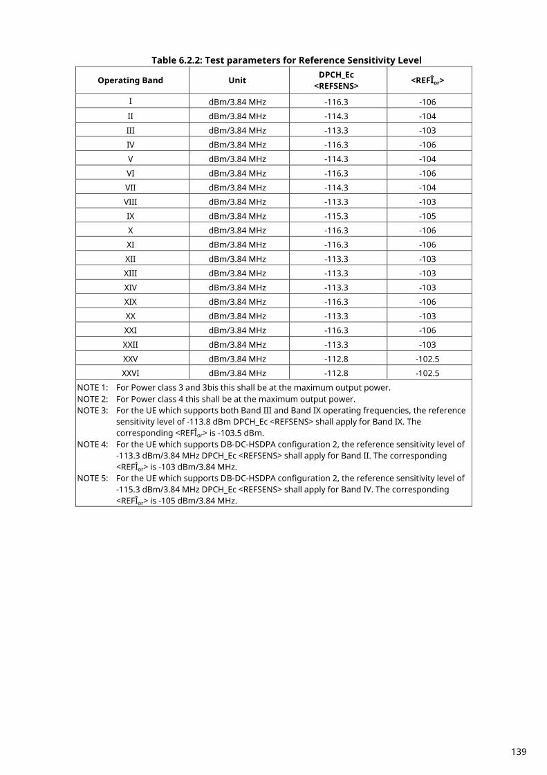
Table 6.2.2: Test parameters for Reference Sensitivity Level
Operating Band Unit DPCH_Ec <REFSENS> <REFÎor>
I dBm/3.84 MHz -116.3 -106
II dBm/3.84 MHz -114.3 -104
III dBm/3.84 MHz -113.3 -103
IV dBm/3.84 MHz -116.3 -106
V dBm/3.84 MHz -114.3 -104
VI dBm/3.84 MHz -116.3 -106
VII dBm/3.84 MHz -114.3 -104
VIII dBm/3.84 MHz -113.3 -103
IX dBm/3.84 MHz -115.3 -105
X dBm/3.84 MHz -116.3 -106
XI dBm/3.84 MHz -116.3 -106
XII dBm/3.84 MHz -113.3 -103
XIII dBm/3.84 MHz -113.3 -103
XIV dBm/3.84 MHz -113.3 -103
XIX dBm/3.84 MHz -116.3 -106
XX dBm/3.84 MHz -113.3 -103
XXI dBm/3.84 MHz -116.3 -106
XXII dBm/3.84 MHz -113.3 -103
XXV dBm/3.84 MHz -112.8 -102.5
XXVI dBm/3.84 MHz -112.8 -102.5
NOTE 1: For Power class 3 and 3bis this shall be at the maximum output power. NOTE 2: For Power class 4 this shall be at the maximum output power. NOTE 3: For the UE which supports both Band III and Band IX operating frequencies, the reference
sensitivity level of -113.8 dBm DPCH_Ec <REFSENS> shall apply for Band IX. The corresponding <REFÎor> is -103.5 dBm.
NOTE 4: For the UE which supports DB-DC-HSDPA configuration 2, the reference sensitivity level of -113.3 dBm/3.84 MHz DPCH_Ec <REFSENS> shall apply for Band II. The corresponding <REFÎor> is -103 dBm/3.84 MHz.
NOTE 5: For the UE which supports DB-DC-HSDPA configuration 2, the reference sensitivity level of -115.3 dBm/3.84 MHz DPCH_Ec <REFSENS> shall apply for Band IV. The corresponding <REFÎor> is -105 dBm/3.84 MHz.
139
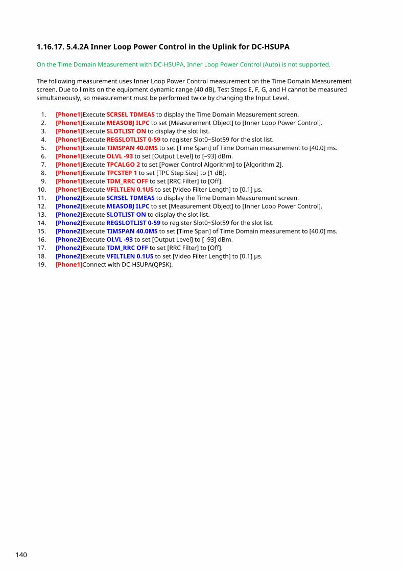
1.16.17. 5.4.2A Inner Loop Power Control in the Uplink for DC-HSUPA On the Time Domain Measurement with DC-HSUPA, Inner Loop Power Control (Auto) is not supported. The following measurement uses Inner Loop Power Control measurement on the Time Domain Measurement screen. Due to limits on the equipment dynamic range (40 dB), Test Steps E, F, G, and H cannot be measured simultaneously, so measurement must be performed twice by changing the Input Level.
1. [Phone1]Execute SCRSEL TDMEAS to display the Time Domain Measurement screen. 2. [Phone1]Execute MEASOBJ ILPC to set [Measurement Object] to [Inner Loop Power Control]. 3. [Phone1]Execute SLOTLIST ON to display the slot list. 4. [Phone1]Execute REGSLOTLIST 0-59 to register Slot0~Slot59 for the slot list. 5. [Phone1]Execute TIMSPAN 40.0MS to set [Time Span] of Time Domain measurement to [40.0] ms. 6. [Phone1]Execute OLVL -93 to set [Output Level] to [–93] dBm. 7. [Phone1]Execute TPCALGO 2 to set [Power Control Algorithm] to [Algorithm 2]. 8. [Phone1]Execute TPCSTEP 1 to set [TPC Step Size] to [1 dB]. 9. [Phone1]Execute TDM_RRC OFF to set [RRC Filter] to [Off].
10. [Phone1]Execute VFILTLEN 0.1US to set [Video Filter Length] to [0.1] µs. 11. [Phone2]Execute SCRSEL TDMEAS to display the Time Domain Measurement screen. 12. [Phone2]Execute MEASOBJ ILPC to set [Measurement Object] to [Inner Loop Power Control]. 13. [Phone2]Execute SLOTLIST ON to display the slot list. 14. [Phone2]Execute REGSLOTLIST 0-59 to register Slot0~Slot59 for the slot list. 15. [Phone2]Execute TIMSPAN 40.0MS to set [Time Span] of Time Domain measurement to [40.0] ms. 16. [Phone2]Execute OLVL -93 to set [Output Level] to [–93] dBm. 17. [Phone2]Execute TDM_RRC OFF to set [RRC Filter] to [Off]. 18. [Phone2]Execute VFILTLEN 0.1US to set [Video Filter Length] to [0.1] µs. 19. [Phone1]Connect with DC-HSUPA(QPSK).
140

1.16.17.1. Inner Loop Power Control Parameter Inner Loop Power Control Parameter of Call Processing Parameter is the steady-state setting of the TPC command. When Power Control Bit Pattern is set to [Inner Loop Power Control], the TPC command is sent automatically to adjust UE output power to be Input Level. In the case of Inner Loop Power Control Parameter of Time Domain Parameter, the TPC command between Slot 0 and the specified Slot is set only when Measurement Object of Time Domain Measurement is measured using Inner Loop Power Control. After sending the specified number of slots, the TPC command set at Call Processing Parameter is sent. Sometimes, at Inner Loop Power Control measurement, the UE output power must be set lower (or higher) than [Input Level] before measurement. Examples of how to set Input Level to +30 dBm and UE output power to -10 dBm are shown below.
1. [Phone1]Execute TPCPAT ILPC to set [Power Control Bit Pattern] to [Inner Loop Power Control]. 2. [Phone1]Execute ILVL -10.0 to set [Input Level] to [–10.0] dBm. 3. [Phone1]Wait until the UE power becomes –10.0 dBm. 4. [Phone1]Execute TPCPAT ALT to set [Power Control Bit Pattern] to [Alternate]. 5. [Phone1]Execute ILVL 30.0 to set [Input Level] to [+30.0] dBm. 6. [Phone2]Execute TPCPAT ILPC to set [Power Control Bit Pattern] to [Inner Loop Power Control]. 7. [Phone2]Execute ILVL -10.0 to set [Input Level] to [–10.0] dBm. 8. [Phone2]Wait until the UE power becomes –10.0 dBm. 9. [Phone2]Execute TPCPAT ALT to set [Power Control Bit Pattern] to [Alternate].
10. [Phone2]Execute ILVL 30.0 to set [Input Level] to [+30.0] dBm.
141

1.16.17.2. Measurement of Inner Loop Power Control in Uplink for DC-HSUPA
To connect with DC-HSUPA(QPSK), See 1.16.3 Connection with DC-HSUPA(QPSK). [Step A]
1. [Phone1]Execute ILP_TPC A to set [TPC Method] to [Step A]. 2. [Phone2] Execute HSSCCH OFF to set [HSSCCH power] to [Off] for Secondary Serving Cell. 3. [Phone1]Execute TPCALGO 2 to set [Power Control Algorithm] to [Algorithm 2]. 4. [Phone2] Execute HSSCCH ON to set [HSSCCH power] to [On] for Secondary Serving Cell. 5. [Phone1]Execute TPCSTEP 1 to set [TPC Step Size] to [1 dB]. 6. [Phone1]Execute TPCPAT ILPC to set [Power Control Bit Pattern] to [Inner Loop Power Control]. 7. [Phone1]Execute ILVL -10.0 to set [Input Level] to [–10.0] dBm. 8. [Phone1]Execute TPCPAT ALT to set [Power Control Bit Pattern] to [Alternate]. 9. [Phone1]Execute ILVL 0.0 to set [Input Level] to [0.0] dBm.
10. [Phone2]Execute ILP_TPC A to set [TPC Method] to [Step A]. 11. [Phone2]Execute TPCPAT ILPC to set [Power Control Bit Pattern] to [Inner Loop Power Control]. 12. [Phone2]Execute ILVL -10.0 to set [Input Level] to [–10.0] dBm. 13. [Phone2]Execute TPCPAT ALT to set [Power Control Bit Pattern] to [Alternate]. 14. [Phone2]Execute ILVL 0.0 to set [Input Level] to [0.0] dBm. 15. [Phone1]Execute SNGLS to perform measurement. 16. [Phone2]Execute SNGLS to perform measurement. 17. [Phone1]Repeat MSTAT? until the response becomes 0. 18. [Phone2]Repeat MSTAT? until the response becomes 0. 19. [Phone1]Execute SLOT_PWR? ALL to read the measurement result. 20. [Phone2]Execute SLOT_PWR? ALL to read the measurement result. 21. Confirm the difference in mean power between adjacent slots on each carrier shall be within the prescribed
range for a TPC_cmd of 0, as given in 3GPP TS34.121 table 5.4.2A.5.1. 22. Confirm the change in mean power over 10 consecutive slots on each carrier shall be within the prescribed
range for a TPC_cmd group of 0, as given in 3GPP TS34.121 table 5.4.2A.5.2 The interval of two SNGLS above should be less than 400ms.
[Step B] 1. [Phone1]Execute ILP_TPC B to set [TPC Method] to [Step B]. 2. [Phone1]Execute TPCALGO 2 to set [Power Control Algorithm] to [Algorithm 2]. 3. [Phone1]Execute TPCSTEP 1 to set [TPC Step Size] to [1 dB]. 4. [Phone1]Execute TPCPAT ALT to set [Power Control Bit Pattern] to [Alternate]. 5. [Phone1]Execute ILVL 0.0 to set [Input Level] to [0.0] dBm. 6. [Phone2]Execute ILP_TPC B to set [TPC Method] to [Step B]. 7. [Phone2]Execute TPCPAT ALT to set [Power Control Bit Pattern] to [Alternate]. 8. [Phone2]Execute ILVL 0.0 to set [Input Level] to [0.0] dBm. 9. [Phone1]Execute SNGLS to perform measurement.
10. [Phone2]Execute SNGLS to perform measurement. 11. [Phone1]Repeat MSTAT? until the response becomes 0. 12. [Phone2]Repeat MSTAT? until the response becomes 0. 13. [Phone1]Execute SLOT_PWR? ALL to read the measurement result. 14. [Phone2]Execute SLOT_PWR? ALL to read the measurement result. 15. Confirm the difference in mean power between adjacent slots on each carrier shall be within the prescribed
range given in 3GPP TS34.121 table 5.4.2A.5.1, given that every 5th TPC_cmd should have the value +1, with a step size of 1 dB, and all other TPC_cmd should have the value 0.
16. Confirm the change in mean power over 50 consecutive slots on each carrier shall be within the prescribed range for a TPC_cmd group of 0,0,0,0,+1, as given in 3GPP TS34.121 table 5.4.2A.5.2.
The interval of two SNGLS above should be less than 400ms.
142

[Step C] 1. [Phone1]Execute ILP_TPC C to set [TPC Method] to [Step C]. 2. [Phone1]Execute TPCALGO 2 to set [Power Control Algorithm] to [Algorithm 2]. 3. [Phone1]Execute TPCSTEP 1 to set [TPC Step Size] to [1 dB]. 4. [Phone1]Execute TPCPAT ALT to set [Power Control Bit Pattern] to [Alternate]. 5. [Phone1]Execute ILVL 0.0 to set [Input Level] to [0.0] dBm. 6. [Phone2]Execute ILP_TPC C to set [TPC Method] to [Step C]. 7. [Phone2]Execute TPCPAT ALT to set [Power Control Bit Pattern] to [Alternate]. 8. [Phone2]Execute ILVL 0.0 to set [Input Level] to [0.0] dBm. 9. [Phone1]Execute SNGLS to perform measurement.
10. [Phone2]Execute SNGLS to perform measurement. 11. [Phone1]Repeat MSTAT? until the response becomes 0. 12. [Phone2]Repeat MSTAT? until the response becomes 0. 13. [Phone1]Execute SLOT_PWR? ALL to read the measurement result. 14. [Phone2]Execute SLOT_PWR? ALL to read the measurement result. 15. Confirm the difference in mean power between adjacent slots on each carrier shall be within the prescribed
range given in 3GPP TS34.121 table 5.4.2A.5.1, given that every 5th TPC_cmd should have the value −1, with a step size of 1 dB, and all other TPC_cmd should have the value 0.
16. Confirm the change in mean power over 50 consecutive slots on each carrier shall be within the prescribed range for a TPC_cmd group of 0,0,0,0,-1, as given in 3GPP TS34.121 table 5.4.2A.5.2.
The interval of two SNGLS above should be less than 400ms. [Step D]
1. [Phone1]Execute ILP_TPC D to set [TPC Method] to [Step D]. 2. [Phone2] Execute HSSCCH OFF to set [HSSCCH power] to [Off] for Secondary Serving Cell. 3. [Phone1]Execute TPCALGO 1 to set [Power Control Algorithm] to [Algorithm 1]. 4. [Phone2] Execute HSSCCH ON to set [HSSCCH power] to [On] for Secondary Serving Cell. 5. [Phone1]Execute TPCSTEP 1 to set [TPC Step Size] to [1 dB]. 6. [Phone1]Execute TPCPAT ALT to set [Power Control Bit Pattern] to [Alternate]. 7. [Phone1]Execute ILVL 25.0 to set [Input Level] to [+25.0] dBm. 8. [Phone2]Execute ILP_TPC D to set [TPC Method] to [Step D]. 9. [Phone2]Execute TPCPAT ALT to set [Power Control Bit Pattern] to [Alternate].
10. [Phone2]Execute ILVL 25.0 to set [Input Level] to [+25.0] dBm. 11. [Phone1]Execute SNGLS to perform measurement. 12. [Phone2]Execute SNGLS to perform measurement. 13. [Phone1]Repeat MSTAT? until the response becomes 0. 14. [Phone2]Repeat MSTAT? until the response becomes 0. 15. [Phone1]Execute SLOT_PWR? ALL to read the measurement result. 16. [Phone2]Execute SLOT_PWR? ALL to read the measurement result. 17. Confirm the UE output power is above the maximum power threshold. The interval of two SNGLS above should be less than 400ms.
143

[Step E 1] 1. [Phone1]Execute ILP_TPC E to set [TPC Method] to [Step E]. 2. [Phone1]Execute ILP_CMDSLOT E,40 to set [Length] of Test Step E to [40] Slot. 3. [Phone1]Execute TPCALGO 1 to set [Power Control Algorithm] to [Algorithm 1]. 4. [Phone1]Execute TPCSTEP 1 to set [TPC Step Size] to [1 dB]. 5. [Phone1]Execute TPCPAT ALT to set [Power Control Bit Pattern] to [Alternate]. 6. [Phone1]Execute ILVL 25.0 to set [Input Level] to [+25.0] dBm. 7. [Phone2]Execute ILP_TPC E to set [TPC Method] to [Step E]. 8. [Phone2]Execute ILP_CMDSLOT E,40 to set [Length] of Test Step E to [40] Slot. 9. [Phone2]Execute TPCPAT ALT to set [Power Control Bit Pattern] to [Alternate].
10. [Phone2]Execute ILVL 25.0 to set [Input Level] to [+25.0] dBm. 11. [Phone1]Execute SNGLS to perform measurement. 12. [Phone2]Execute SNGLS to perform measurement. 13. [Phone1]Repeat MSTAT? until the response becomes 0. 14. [Phone2]Repeat MSTAT? until the response becomes 0. 15. [Phone1]Execute SLOT_PWR? ALL to read the measurement result. 16. [Phone2]Execute SLOT_PWR? ALL to read the measurement result. The interval of two SNGLS above should be less than 400ms. [Step E 2]
1. [Phone1]Execute ILP_TPC E to set [TPC Method] to [Step E]. 2. [Phone1]Execute ILP_CMDSLOT E,40 to set [Length] of Test Step E to [40] Slot. 3. [Phone1]Execute TPCALGO 1 to set [Power Control Algorithm] to [Algorithm 1]. 4. [Phone1]Execute TPCSTEP 1 to set [TPC Step Size] to [1 dB]. 5. [Phone1]Execute TPCPAT ALT to set [Power Control Bit Pattern] to [Alternate]. 6. [Phone1]Execute ILVL -15.0 to set [Input Level] to [–15.0] dBm. 7. [Phone2]Execute ILP_TPC E to set [TPC Method] to [Step E]. 8. [Phone2]Execute ILP_CMDSLOT E,40 to set [Length] of Test Step E to [40] Slot. 9. [Phone2]Execute TPCPAT ALT to set [Power Control Bit Pattern] to [Alternate].
10. [Phone2]Execute ILVL -15.0 to set [Input Level] to [–15.0] dBm. 11. [Phone1]Execute SNGLS to perform measurement. 12. [Phone2]Execute SNGLS to perform measurement. 13. [Phone1]Repeat MSTAT? until the response becomes 0. 14. [Phone2]Repeat MSTAT? until the response becomes 0. 15. [Phone1]Execute SLOT_PWR? ALL to read the measurement result. 16. [Phone2]Execute SLOT_PWR? ALL to read the measurement result. 17. Combine segmentations at Step E1 and E2. 18. Confirm the difference in mean power between adjacent slots on each carrier shall be within the prescribed
range given in 3GPP TS34.121 table 5.4.2A.5.1 for a TPC_cmd of −1 and step size of 1 dB. This applies when the original (reference) timeslot power and the target timeslot power are between the Min power threshold for test and the Max power threshold for test derived from the Measured Maximum output power in Step D. For the power step adjacent to the Min or Max power threshold for test, the lower step size requirement does not apply.
19. Confirm the change in mean power over 10 consecutive slots on each carrier shall be within the prescribed range for a TPC_cmd group of −1, and step size of 1 dB as given in 3GPP TS34.121 table 5.4.2A.5.2. This applies when the original (reference) timeslot power and the target timeslot power are between the Min power threshold for test and the Max power threshold for test derived from the Measured Maximum output power in Step D. The power step adjacent to the Min or Max power threshold for test should not be part of the 10 consecutive slots tested.
The interval of two SNGLS above should be less than 400ms.
144

[Step F 1] 1. [Phone1]Execute ILP_TPC F to set [TPC Method] to [Step F]. 2. [Phone1]Execute ILP_CMDSLOT F,40 to set [Length] of Test Step F to [40] Slot. 3. [Phone1]Execute TPCALGO 1 to set [Power Control Algorithm] to [Algorithm 1]. 4. [Phone1]Execute TPCSTEP 1 to set [TPC Step Size] to [1 dB]. 5. [Phone1]Execute TPCPAT ALT to set [Power Control Bit Pattern] to [Alternate]. 6. [Phone1]Execute ILVL -15.0 to set [Input Level] to [–15.0] dBm. 7. [Phone2]Execute ILP_TPC F to set [TPC Method] to [Step F]. 8. [Phone2]Execute ILP_CMDSLOT F,40 to set [Length] of Test Step F to [40] Slot. 9. [Phone2]Execute TPCPAT ALT to set [Power Control Bit Pattern] to [Alternate].
10. [Phone2]Execute ILVL -15.0 to set [Input Level] to [–15.0] dBm. 11. [Phone1]Execute SNGLS to perform measurement. 12. [Phone2]Execute SNGLS to perform measurement. 13. [Phone1]Repeat MSTAT? until the response becomes 0. 14. [Phone2]Repeat MSTAT? until the response becomes 0. 15. [Phone1]Execute SLOT_PWR? ALL to read the measurement result. 16. [Phone2]Execute SLOT_PWR? ALL to read the measurement result. The interval of two SNGLS above should be less than 400ms. [Step F 2]
1. [Phone1]Execute ILP_TPC F to set [TPC Method] to [Step F]. 2. [Phone1]Execute ILP_CMDSLOT F,40 to set [Length] of Test Step F to [40] Slot. 3. [Phone1]Execute TPCALGO 1 to set [Power Control Algorithm] to [Algorithm 1]. 4. [Phone1]Execute TPCSTEP 1 to set [TPC Step Size] to [1 dB]. 5. [Phone1]Execute TPCPAT ALT to set [Power Control Bit Pattern] to [Alternate]. 6. [Phone1]Execute ILVL 25.0 to set [Input Level] to [+25.0] dBm. 7. [Phone2]Execute ILP_TPC F to set [TPC Method] to [Step F]. 8. [Phone2]Execute ILP_CMDSLOT F,40 to set [Length] of Test Step F to [40] Slot. 9. [Phone2]Execute TPCPAT ALT to set [Power Control Bit Pattern] to [Alternate].
10. [Phone2]Execute ILVL 25.0 to set [Input Level] to [+25.0] dBm. 11. [Phone1]Execute SNGLS to perform measurement. 12. [Phone2]Execute SNGLS to perform measurement. 13. [Phone1]Repeat MSTAT? until the response becomes 0. 14. [Phone2]Repeat MSTAT? until the response becomes 0. 15. [Phone1]Execute SLOT_PWR? ALL to read the measurement result. 16. [Phone2]Execute SLOT_PWR? ALL to read the measurement result. 17. Combine segmentations at Step F1 and F2. 18. Confirm the difference in mean power between adjacent slots on each carrier shall be within the prescribed
range given in 3GPP TS34.121 table 5.4.2A.5.1 for a TPC_cmd of +1 and step size of 1 dB. This applies when the original (reference) timeslot power and the target timeslot power are between the Min power threshold for test and the Max power threshold for test derived from the Measured Maximum output power in Step F. For the power step adjacent to the Min or Max power threshold for test, the lower step size requirement does not apply.
19. Confirm the change in mean power over 10 consecutive slots on each carrier shall be within the prescribed range for a TPC_cmd group of +1, and step size of 1 dB as given in 3GPP TS34.121 table 5.4.2A.5.2. This applies when the original (reference) timeslot power and the target timeslot power are between the Min power threshold for test and the Max power threshold for test derived from the Measured Maximum output power in Step F. The power step adjacent to the Min or Max power threshold for test should not be part of the 10 consecutive slots tested.
The interval of two SNGLS above should be less than 400ms.
145

[Step G 1] 1. [Phone1]Execute ILP_TPC G to set [TPC Method] to [Step G]. 2. [Phone1]Execute ILP_CMDSLOT G,20 to set [Length] of Test Step G to [20] Slot. 3. [Phone1]Execute TPCALGO 1 to set [Power Control Algorithm] to [Algorithm 1]. 4. [Phone2] Execute HSSCCH OFF to set [HSSCCH power] to [Off] for Secondary Serving Cell. 5. [Phone1]Execute TPCSTEP 2 to set [TPC Step Size] to [2 dB]. 6. [Phone2] Execute HSSCCH ON to set [HSSCCH power] to [On] for Secondary Serving Cell. 7. [Phone1]Execute TPCPAT ALT to set [Power Control Bit Pattern] to [Alternate]. 8. [Phone1]Execute ILVL 25.0 to set [Input Level] to [+25.0] dBm. 9. [Phone2]Execute ILP_TPC G to set [TPC Method] to [Step G].
10. [Phone2]Execute ILP_CMDSLOT G,20 to set [Length] of Test Step G to [20] Slot. 11. [Phone2]Execute TPCPAT ALT to set [Power Control Bit Pattern] to [Alternate]. 12. [Phone2]Execute ILVL 25.0 to set [Input Level] to [+25.0] dBm. 13. [Phone1]Execute SNGLS to perform measurement. 14. [Phone2]Execute SNGLS to perform measurement. 15. [Phone1]Repeat MSTAT? until the response becomes 0. 16. [Phone2]Repeat MSTAT? until the response becomes 0. 17. [Phone1]Execute SLOT_PWR? ALL to read the measurement result. 18. [Phone2]Execute SLOT_PWR? ALL to read the measurement result. The interval of two SNGLS above should be less than 400ms. [Step G 2]
1. [Phone1]Execute ILP_TPC G to set [TPC Method] to [Step G]. 2. [Phone1]Execute ILP_CMDSLOT G,20 to set [Length] of Test Step G to [20] Slot. 3. [Phone1]Execute TPCALGO 1 to set [Power Control Algorithm] to [Algorithm 1]. 4. [Phone1]Execute TPCSTEP 2 to set [TPC Step Size] to [2 dB]. 5. [Phone1]Execute TPCPAT ALT to set [Power Control Bit Pattern] to [Alternate]. 6. [Phone1]Execute ILVL -15.0 to set [Input Level] to [–15.0] dBm. 7. [Phone2]Execute ILP_TPC G to set [TPC Method] to [Step G]. 8. [Phone2]Execute ILP_CMDSLOT G,20 to set [Length] of Test Step G to [20] Slot. 9. [Phone2]Execute TPCPAT ALT to set [Power Control Bit Pattern] to [Alternate].
10. [Phone2]Execute ILVL -15.0 to set [Input Level] to [–15.0] dBm. 11. [Phone1]Execute SNGLS to perform measurement. 12. [Phone2]Execute SNGLS to perform measurement. 13. [Phone1]Repeat MSTAT? until the response becomes 0. 14. [Phone2]Repeat MSTAT? until the response becomes 0. 15. [Phone1]Execute SLOT_PWR? ALL to read the measurement result. 16. [Phone2]Execute SLOT_PWR? ALL to read the measurement result. 17. Combine segmentations at Step G1 and G2. 18. Confirm the difference in mean power between adjacent slots on each carrier shall be within the prescribed
range given in 3GPP TS34.121 table 5.4.2A.5.1 for a TPC_cmd of −1 and step size of 2 dB. This applies when the original (reference) timeslot power and the target timeslot power are between the Min power threshold for test and the Max power threshold for test derived from the Measured Maximum output power in Step F. For the power step adjacent to the Min or Max power threshold for test, the lower step size requirement does not apply.
19. Confirm the change in mean power over 10 consecutive slots on each carrier shall be within the prescribed range for a TPC_cmd group of −1, and step size of 2 dB as given in 3GPP TS34.121 table 5.4.2A.5.2. This applies when the original (reference) timeslot power and the target timeslot power are between the Min power threshold for test and the Max power threshold for test derived from the Measured Maximum output power in Step F. The power step adjacent to the Min or Max power threshold for test should not be part of the 10 consecutive slots.
The interval of two SNGLS above should be less than 400ms.
146
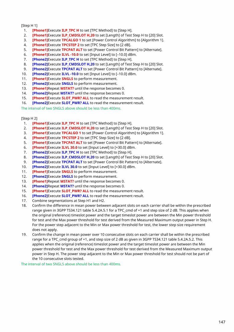
[Step H 1] 1. [Phone1]Execute ILP_TPC H to set [TPC Method] to [Step H]. 2. [Phone1]Execute ILP_CMDSLOT H,20 to set [Length] of Test Step H to [20] Slot. 3. [Phone1]Execute TPCALGO 1 to set [Power Control Algorithm] to [Algorithm 1]. 4. [Phone1]Execute TPCSTEP 2 to set [TPC Step Size] to [2 dB]. 5. [Phone1]Execute TPCPAT ALT to set [Power Control Bit Pattern] to [Alternate]. 6. [Phone1]Execute ILVL -10.0 to set [Input Level] to [–10.0] dBm. 7. [Phone2]Execute ILP_TPC H to set [TPC Method] to [Step H]. 8. [Phone2]Execute ILP_CMDSLOT H,20 to set [Length] of Test Step H to [20] Slot. 9. [Phone2]Execute TPCPAT ALT to set [Power Control Bit Pattern] to [Alternate].
10. [Phone2]Execute ILVL -10.0 to set [Input Level] to [–10.0] dBm. 11. [Phone1]Execute SNGLS to perform measurement. 12. [Phone2]Execute SNGLS to perform measurement. 13. [Phone1]Repeat MSTAT? until the response becomes 0. 14. [Phone2]Repeat MSTAT? until the response becomes 0. 15. [Phone1]Execute SLOT_PWR? ALL to read the measurement result. 16. [Phone2]Execute SLOT_PWR? ALL to read the measurement result. The interval of two SNGLS above should be less than 400ms. [Step H 2]
1. [Phone1]Execute ILP_TPC H to set [TPC Method] to [Step H]. 2. [Phone1]Execute ILP_CMDSLOT H,20 to set [Length] of Test Step H to [20] Slot. 3. [Phone1]Execute TPCALGO 1 to set [Power Control Algorithm] to [Algorithm 1]. 4. [Phone1]Execute TPCSTEP 2 to set [TPC Step Size] to [2 dB]. 5. [Phone1]Execute TPCPAT ALT to set [Power Control Bit Pattern] to [Alternate]. 6. [Phone1]Execute ILVL 30.0 to set [Input Level] to [+30.0] dBm. 7. [Phone2]Execute ILP_TPC H to set [TPC Method] to [Step H]. 8. [Phone2]Execute ILP_CMDSLOT H,20 to set [Length] of Test Step H to [20] Slot. 9. [Phone2]Execute TPCPAT ALT to set [Power Control Bit Pattern] to [Alternate].
10. [Phone2]Execute ILVL 30.0 to set [Input Level] to [+30.0] dBm. 11. [Phone1]Execute SNGLS to perform measurement. 12. [Phone2]Execute SNGLS to perform measurement. 13. [Phone1]Repeat MSTAT? until the response becomes 0. 14. [Phone2]Repeat MSTAT? until the response becomes 0. 15. [Phone1]Execute SLOT_PWR? ALL to read the measurement result. 16. [Phone2]Execute SLOT_PWR? ALL to read the measurement result. 17. Combine segmentations at Step H1 and H2. 18. Confirm the difference in mean power between adjacent slots on each carrier shall be within the prescribed
range given in 3GPP TS34.121 table 5.4.2A.5.1 for a TPC_cmd of +1 and step size of 2 dB. This applies when the original (reference) timeslot power and the target timeslot power are between the Min power threshold for test and the Max power threshold for test derived from the Measured Maximum output power in Step H. For the power step adjacent to the Min or Max power threshold for test, the lower step size requirement does not apply.
19. Confirm the change in mean power over 10 consecutive slots on each carrier shall be within the prescribed range for a TPC_cmd group of +1, and step size of 2 dB as given in 3GPP TS34.121 table 5.4.2A.5.2. This applies when the original (reference) timeslot power and the target timeslot power are between the Min power threshold for test and the Max power threshold for test derived from the Measured Maximum output power in Step H. The power step adjacent to the Min or Max power threshold for test should not be part of the 10 consecutive slots tested.
The interval of two SNGLS above should be less than 400ms.
147

20. Confirm the measurement results above with the following table.
3GPP TS 34.121 Table 5.4.2A.5.1: Transmitter power control range
TPC_cmd Transmitter power control range (all units are in dB) 1 dB step size 2 dB step size 3 dB step size
Lower Upper Lower Upper Lower Upper
+1 +0,4 +1,6 +0,85 +3,15 +1,3 +4,7
0 −0,6 +0,6 −0,6 +0,6 −0,6 +0,6
−1 −0,4 −1,6 −0,85 −3,15 −1,3 −4,7
3GPP TS 34.121 Table 5.4.2A.5.2: Transmitter aggregate power control tolerance
TPC_cmd group Transmitter power control range after 10 equal TPC_cmd group
(all units are in dB)
Transmitter power control range after 7
equal TPC_cmd groups (all units are in dB)
1 dB step size 2 dB step size 3 dB step size Lower Upper Lower Upper Lower Upper
+1 +7,7 +12,3 +15,7 +24,3 +15,7 +26,3
0 −1,1 +1,1 −1,1 +1,1 −1,1 +1,1
−1 −7,7 −12,3 −15,7 −24,3 −15,7 −26,3
0,0,0,0,+1 +5,7 +14,3 N/A N/A N/A N/A
0,0,0,0,−1 −5,7 −14,3 N/A N/A N/A N/A
148
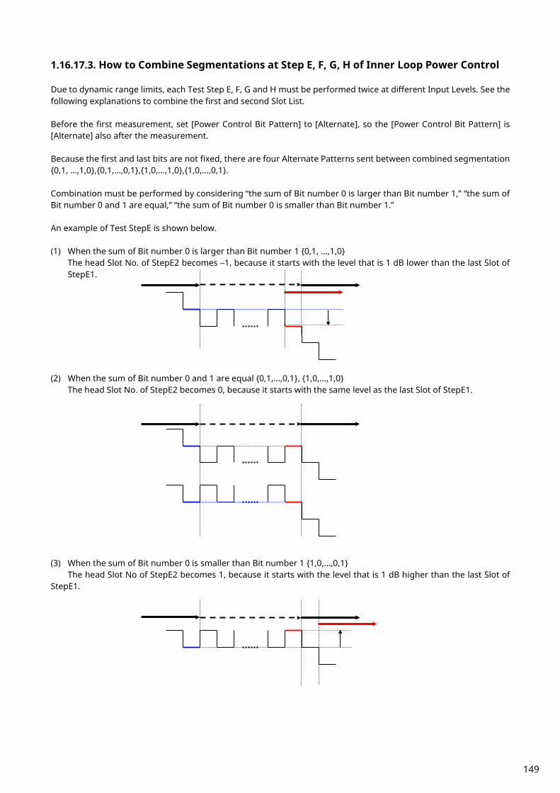
1.16.17.3. How to Combine Segmentations at Step E, F, G, H of Inner Loop Power Control Due to dynamic range limits, each Test Step E, F, G and H must be performed twice at different Input Levels. See the following explanations to combine the first and second Slot List. Before the first measurement, set [Power Control Bit Pattern] to [Alternate], so the [Power Control Bit Pattern] is [Alternate] also after the measurement. Because the first and last bits are not fixed, there are four Alternate Patterns sent between combined segmentation 0,1, …,1,0,0,1,…,0,1,1,0,…,1,0,1,0,…,0,1. Combination must be performed by considering “the sum of Bit number 0 is larger than Bit number 1,” “the sum of Bit number 0 and 1 are equal,” “the sum of Bit number 0 is smaller than Bit number 1.” An example of Test StepE is shown below. (1) When the sum of Bit number 0 is larger than Bit number 1 0,1, …,1,0
The head Slot No. of StepE2 becomes –1, because it starts with the level that is 1 dB lower than the last Slot of StepE1.
(2) When the sum of Bit number 0 and 1 are equal 0,1,…,0,1, 1,0,…,1,0
The head Slot No. of StepE2 becomes 0, because it starts with the same level as the last Slot of StepE1.
(3) When the sum of Bit number 0 is smaller than Bit number 1 1,0,…,0,1
The head Slot No of StepE2 becomes 1, because it starts with the level that is 1 dB higher than the last Slot of StepE1.
149

[Step E] 1. Execute [Step E 1] (see 5.4.2A Inner Loop Power Control in the Uplink for DC-HSUPA.) 2. Execute REGSLOTLIST -1 to register Slot(-1) in slot list. 3. Execute TRGDELAY -0.7MS to set [Trigger Delay] to [–0.7] ms (1Slot length). 4. Execute [Step E 2]. (see 5.4.2A Inner Loop Power Control in the Uplink for DC-HSUPA.) 5. Check the Power difference between the first Slot of Step E 2 and the last Slot of Step E 1. When the difference is <–0.5 dB, the head Slot of Step E 2 becomes –1. When the difference is within ±0.5 dB, the head Slot of Step E 2 becomes 0. When the difference is >0.5 dB, the head Slot of Step E 2 becomes 1.
[Step F]
1. Execute [Step F 1]. (see 5.4.2A Inner Loop Power Control in the Uplink for DC-HSUPA.) 2. Execute REGSLOTLIST -1 to register Slot(-1) in slot list. 3. Execute TRGDELAY -0.7MS to set [Trigger Delay] to [–0.7] ms (1Slot length). 4. Execute [Step F 2]. (see 5.4.2A Inner Loop Power Control in the Uplink for DC-HSUPA.) 5. Check the Power difference between the first Slot of Step F 2 and the last Slot of Step F 1. When the difference is <–0.5 dB, the head Slot of Step F 2 becomes 1. When the difference is within ±0.5 dB, the head Slot of Step F 2 becomes 0. When the difference is >0.5 dB, the head Slot of Step F 2 becomes –1.
[Step G]
1. Execute [Step G 1]. (see 5.4.2A Inner Loop Power Control in the Uplink for DC-HSUPA.) 2. Execute REGSLOTLIST -1 to register Slot(-1) in slot list. 3. Execute TRGDELAY -0.7MS to set [Trigger Delay] to [–0.7] ms (1Slot length). 4. Execute [Step G 2]. (see 5.4.2A Inner Loop Power Control in the Uplink for DC-HSUPA.) 5. Check the Power difference between the first Slot of Step G 2 and the last Slot of Step G 1. When the difference is <–1 dB, the head Slot of Step G 2 becomes –1. When the difference is within ±1 dB, the head Slot of Step G 2 becomes 0. When the difference is >1 dB, the head Slot of Step G 2 becomes 1.
[Step H]
1. Execute [Step H 1]. (see 5.4.2A Inner Loop Power Control in the Uplink for DC-HSUPA.) 2. Execute REGSLOTLIST -1 to register Slot(-1) in slot list. 3. Execute TRGDELAY -0.7MS to set [Trigger Delay] to [–0.7] ms (1Slot length). 4. Execute [Step H 2]. (see 5.4.2A Inner Loop Power Control in the Uplink for DC-HSUPA.) 5. Check the Power difference between the first Slot of Step H 2 and the last Slot of Step H 1. When the difference is <–1 dB, the head Slot of Step H 2 becomes 1. When the difference is within ±1 dB, the head Slot of Step H 2 becomes 0. When the difference is >1 dB, the head Slot of Step H 2 becomes –1.
150

1.16.18. 5.4.3A Minimum Output Power for DC-HSUPA
To connect with DC-HSUPA(QPSK), see 1.16.3 Connection with DC-HSUPA(QPSK).
1. [Phone1]Execute DDPCHTOFS 6 to set [DPCH Timing Offset] to [6]. 2. [Phone1]Execute MAXULPWR 21 to set [Maximum Allowed UL TX Power] to [21.0] dBm. 3. [Phone1]Execute TPCALGO 1 to set [TPC Algorithm] to [2]. 4. [Phone1]Connect with DC-HSUPA(QPSK). 5. [Phone1]Execute OLVL -86.0 to set [Output Level] to [-86.0dBm]. 6. [Phone1]Execute OBW_MEAS OFF to set [Occupied Bandwidth measurement] to [Off]. 7. [Phone1]Execute SMASK_MEAS OFF to set [Spectrum Emission Mask measurement] to [Off]. 8. [Phone1]Execute ADJ_MEAS OFF to set [Adjacent Channel Power measurement] to [Off]. 9. [Phone1]Execute EHICHPAT ACK to set [E-HICH Pattern] to [ACK].
10. [Phone1]Execute ABSGNTVAL 6 to set [Absolute Grant Value] to [6]. 11. [Phone2]Execute DDPCHTOFS 6 to set [DPCH Timing Offset] to [6]. 12. [Phone2]Execute OLVL -86.0 to set [Output Level] to [-86.0dBm]. 13. [Phone2]Execute EHICHPAT ACK to set [E-HICH Pattern] to [ACK]. 14. [Phone2]Execute ABSGNTVAL 6 to set [Absolute Grant Value] to [6]. 15. [Phone1]Execute SCRSEL FMEAS to display the Fundamental Measurement screen. 16. [Phone1]Execute TPCPAT ILPC to set [Power Control Bit Pattern] to [Inner Loop Power Control]. 17. [Phone2]Execute SCRSEL FMEAS to display the Fundamental Measurement screen. 18. [Phone2]Execute TPCPAT ILPC to set [Power Control Bit Pattern] to [Inner Loop Power Control]. 19. [Phone1]Execute ILVL -30.0 to set [Input Level] to [-30.0] dBm. 20. [Phone2]Execute ILVL -30.0 to set [Input Level] to [-30.0] dBm. 21. [Phone1]Execute TPCPAT ALL0 to set [Power Control Bit Pattern] to [All0]. 22. [Phone1]Execute SWP to perform Power measurement. 23. [Phone2]Execute TPCPAT ALL0 to set [Power Control Bit Pattern] to [All0]. 24. [Phone1] Execute AVG_POWER? to read the power measurement result. 25. [Phone1]Execute AVG_POWER_S? to read the Power measurement result as Power2. 26. [Phone1] Confirm the measurement result is lower than -49 dBm. To measure Power, OBW,SEM and ACLR measurement items should be turned off.
151

1.16.19. 5.8A Occupied Bandwidth (OBW) for DC-HSUPA
To connect with DC-HSUPA(QPSK), see 1.16.3 Connection with DC-HSUPA(QPSK).
1. [Phone1]Execute DDPCHTOFS 6 to set [DPCH Timing Offset] to [6]. 2. [Phone1]Execute MAXULPWR 21 to set [Maximum Allowed UL TX Power] to [21.0] dBm. 3. [Phone1]Execute TPCALGO 1 to set [TPC Algorithm] to [1]. 4. [Phone1]Connect with DC-HSUPA(QPSK). 5. [Phone1]Execute OLVL -86.0 to set [Output Level] to [-86.0dBm]. 6. [Phone1]Execute ALLMEASITEMS_OFF to set all measurement items to [Off]. 7. [Phone1]Execute OBW_MEAS ON to set [Occupied Bandwidth measurement] to [On]. 8. [Phone1]Execute EHICHPAT ACK to set [E-HICH Pattern] to [ACK]. 9. [Phone1]Execute ABSGNTVAL 6 to set [Absolute Grant Value] to [6].
10. [Phone2]Execute DDPCHTOFS 6 to set [DPCH Timing Offset] to [6]. 11. [Phone2]Execute OLVL -86.0 to set [Output Level] to [-86.0dBm]. 12. [Phone2]Execute EHICHPAT ACK to set [E-HICH Pattern] to [ACK]. 13. [Phone2]Execute ABSGNTVAL 6 to set [Absolute Grant Value] to [6]. 14. [Phone1]Execute TPCPAT ILPC to set [Power Control Bit Pattern] to [Inner Loop Power Control]. 15. [Phone1]Execute ILVL 10.0 to set [Input Level] to [+10.0] dBm. 16. [Phone2]Execute ILVL 10.0 to set [Input Level] to [+10.0] dBm. 17. Wait 150ms until the UE power becomes 10.0 dBm. 18. [Phone1]Execute ILVL 35.0 to set [Input Level] to [+35.0] dBm. 19. [Phone2]Execute ILVL 35.0 to set [Input Level] to [+35.0] dBm. 20. [Phone1]Execute TPCPAT ALL1 to set [Power Control Bit Pattern] to [All1]. 21. [Phone2]Execute TPCPAT ALL1 to set [Power Control Bit Pattern] to [All1]. 22. [Phone1]Execute SWP to perform Occupied Bandwidth measurement. 23. [Phone1]Execute OBW? to read the Occupied Bandwidth measurement result. 24. [Phone1]Confirm the measurement result is lower than 10 MHz. To measure OBW or SEM or ACLR, other measurement items should be turned off.
152
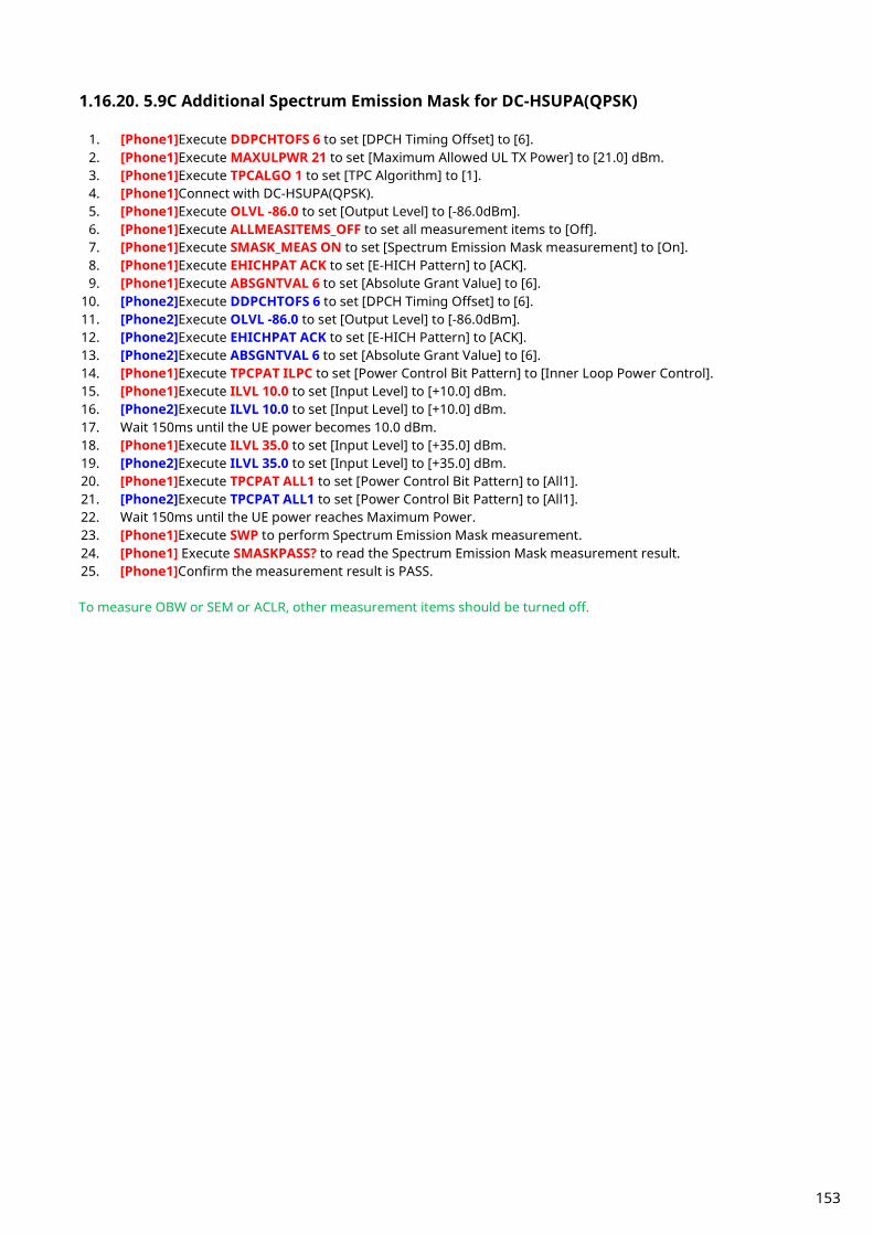
1.16.20. 5.9C Additional Spectrum Emission Mask for DC-HSUPA(QPSK)
1. [Phone1]Execute DDPCHTOFS 6 to set [DPCH Timing Offset] to [6]. 2. [Phone1]Execute MAXULPWR 21 to set [Maximum Allowed UL TX Power] to [21.0] dBm. 3. [Phone1]Execute TPCALGO 1 to set [TPC Algorithm] to [1]. 4. [Phone1]Connect with DC-HSUPA(QPSK). 5. [Phone1]Execute OLVL -86.0 to set [Output Level] to [-86.0dBm]. 6. [Phone1]Execute ALLMEASITEMS_OFF to set all measurement items to [Off]. 7. [Phone1]Execute SMASK_MEAS ON to set [Spectrum Emission Mask measurement] to [On]. 8. [Phone1]Execute EHICHPAT ACK to set [E-HICH Pattern] to [ACK]. 9. [Phone1]Execute ABSGNTVAL 6 to set [Absolute Grant Value] to [6].
10. [Phone2]Execute DDPCHTOFS 6 to set [DPCH Timing Offset] to [6]. 11. [Phone2]Execute OLVL -86.0 to set [Output Level] to [-86.0dBm]. 12. [Phone2]Execute EHICHPAT ACK to set [E-HICH Pattern] to [ACK]. 13. [Phone2]Execute ABSGNTVAL 6 to set [Absolute Grant Value] to [6]. 14. [Phone1]Execute TPCPAT ILPC to set [Power Control Bit Pattern] to [Inner Loop Power Control]. 15. [Phone1]Execute ILVL 10.0 to set [Input Level] to [+10.0] dBm. 16. [Phone2]Execute ILVL 10.0 to set [Input Level] to [+10.0] dBm. 17. Wait 150ms until the UE power becomes 10.0 dBm. 18. [Phone1]Execute ILVL 35.0 to set [Input Level] to [+35.0] dBm. 19. [Phone2]Execute ILVL 35.0 to set [Input Level] to [+35.0] dBm. 20. [Phone1]Execute TPCPAT ALL1 to set [Power Control Bit Pattern] to [All1]. 21. [Phone2]Execute TPCPAT ALL1 to set [Power Control Bit Pattern] to [All1]. 22. Wait 150ms until the UE power reaches Maximum Power. 23. [Phone1]Execute SWP to perform Spectrum Emission Mask measurement. 24. [Phone1] Execute SMASKPASS? to read the Spectrum Emission Mask measurement result. 25. [Phone1]Confirm the measurement result is PASS. To measure OBW or SEM or ACLR, other measurement items should be turned off.
153
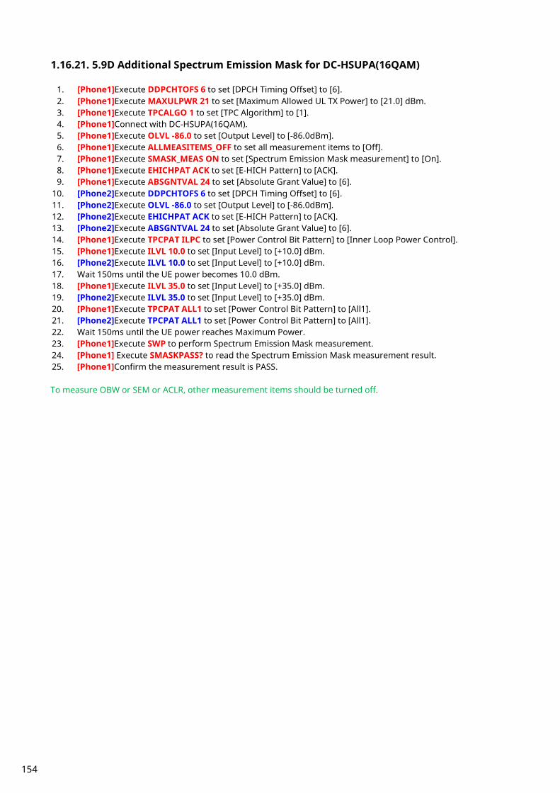
1.16.21. 5.9D Additional Spectrum Emission Mask for DC-HSUPA(16QAM)
1. [Phone1]Execute DDPCHTOFS 6 to set [DPCH Timing Offset] to [6]. 2. [Phone1]Execute MAXULPWR 21 to set [Maximum Allowed UL TX Power] to [21.0] dBm. 3. [Phone1]Execute TPCALGO 1 to set [TPC Algorithm] to [1]. 4. [Phone1]Connect with DC-HSUPA(16QAM). 5. [Phone1]Execute OLVL -86.0 to set [Output Level] to [-86.0dBm]. 6. [Phone1]Execute ALLMEASITEMS_OFF to set all measurement items to [Off]. 7. [Phone1]Execute SMASK_MEAS ON to set [Spectrum Emission Mask measurement] to [On]. 8. [Phone1]Execute EHICHPAT ACK to set [E-HICH Pattern] to [ACK]. 9. [Phone1]Execute ABSGNTVAL 24 to set [Absolute Grant Value] to [6].
10. [Phone2]Execute DDPCHTOFS 6 to set [DPCH Timing Offset] to [6]. 11. [Phone2]Execute OLVL -86.0 to set [Output Level] to [-86.0dBm]. 12. [Phone2]Execute EHICHPAT ACK to set [E-HICH Pattern] to [ACK]. 13. [Phone2]Execute ABSGNTVAL 24 to set [Absolute Grant Value] to [6]. 14. [Phone1]Execute TPCPAT ILPC to set [Power Control Bit Pattern] to [Inner Loop Power Control]. 15. [Phone1]Execute ILVL 10.0 to set [Input Level] to [+10.0] dBm. 16. [Phone2]Execute ILVL 10.0 to set [Input Level] to [+10.0] dBm. 17. Wait 150ms until the UE power becomes 10.0 dBm. 18. [Phone1]Execute ILVL 35.0 to set [Input Level] to [+35.0] dBm. 19. [Phone2]Execute ILVL 35.0 to set [Input Level] to [+35.0] dBm. 20. [Phone1]Execute TPCPAT ALL1 to set [Power Control Bit Pattern] to [All1]. 21. [Phone2]Execute TPCPAT ALL1 to set [Power Control Bit Pattern] to [All1]. 22. Wait 150ms until the UE power reaches Maximum Power. 23. [Phone1]Execute SWP to perform Spectrum Emission Mask measurement. 24. [Phone1] Execute SMASKPASS? to read the Spectrum Emission Mask measurement result. 25. [Phone1]Confirm the measurement result is PASS. To measure OBW or SEM or ACLR, other measurement items should be turned off.
154

1.16.22. 5.10C Adjacent Channel Leakage Power Ratio (ACLR) with E-DCH for DC-HSUPA(QPSK)
1. [Phone1]Execute DDPCHTOFS 6 to set [DPCH Timing Offset] to [6]. 2. [Phone1]Execute MAXULPWR 21 to set [Maximum Allowed UL TX Power] to [21.0] dBm. 3. [Phone1]Execute TPCALGO 1 to set [TPC Algorithm] to [1]. 4. [Phone1]Connect with DC-HSUPA(QPSK). 5. [Phone1]Execute OLVL -86.0 to set [Output Level] to [-86.0dBm]. 6. [Phone1]Execute ALLMEASITEMS_OFF to set all measurement items to [Off]. 7. [Phone1]Execute ADJ_MEAS ON to set [Adjacent Channel Power measurement] to [On]. 8. [Phone1]Execute EHICHPAT ACK to set [E-HICH Pattern] to [ACK]. 9. [Phone1]Execute ABSGNTVAL 6 to set [Absolute Grant Value] to [6].
10. [Phone2]Execute DDPCHTOFS 6 to set [DPCH Timing Offset] to [6]. 11. [Phone2]Execute OLVL -86.0 to set [Output Level] to [-86.0dBm]. 12. [Phone2]Execute EHICHPAT ACK to set [E-HICH Pattern] to [ACK]. 13. [Phone2]Execute ABSGNTVAL 6 to set [Absolute Grant Value] to [6]. 14. [Phone1]Execute TPCPAT ILPC to set [Power Control Bit Pattern] to [Inner Loop Power Control]. 15. [Phone1]Execute ILVL 10.0 to set [Input Level] to [+10.0] dBm. 16. [Phone2]Execute ILVL 10.0 to set [Input Level] to [+10.0] dBm. 17. Wait 150ms until the UE power becomes 10.0 dBm. 18. [Phone1]Execute ILVL 35.0 to set [Input Level] to [+35.0] dBm. 19. [Phone2]Execute ILVL 35.0 to set [Input Level] to [+35.0] dBm. 20. [Phone1]Execute TPCPAT ALL1 to set [Power Control Bit Pattern] to [All1]. 21. [Phone2]Execute TPCPAT ALL1 to set [Power Control Bit Pattern] to [All1]. 22. Wait 150ms until the UE power reaches Maximum Power. 23. [Phone1]Execute SWP to perform Adjacent Channel Power measurement. 24. [Phone1]Execute AVG_MODPWR? LOW12.5 to read the Adjacent Channel Power measurement result. 25. [Phone1]Confirm the measurement result is lower than -35.2 dB. 26. [Phone1]Execute AVG_MODPWR? LOW7.5 to read the Adjacent Channel Power measurement result. 27. [Phone1]Confirm the measurement result is lower than -32.2 dB. 28. [Phone1]Execute AVG_MODPWR? UP7.5 to read the Adjacent Channel Power measurement result. 29. [Phone1]Confirm the measurement result is lower than -32.2 dB. 30. [Phone1]Execute AVG_MODPWR? UP12.5 to read the Adjacent Channel Power measurement result. 31. [Phone1]Confirm the measurement result is lower than -35.2 dB.
To measure OBW or SEM or ACLR, other measurement items should be turned off.
1.16.23. 5.10D Adjacent Channel Leakage Power Ratio (ACLR) with E-DCH for DC-HSUPA(16QAM)
1. [Phone1]Execute DDPCHTOFS 6 to set [DPCH Timing Offset] to [6]. 2. [Phone1]Execute MAXULPWR 21 to set [Maximum Allowed UL TX Power] to [21.0] dBm. 3. [Phone1]Execute TPCALGO 1 to set [TPC Algorithm] to [1]. 4. [Phone1]Connect with DC-HSUPA(16QAM). 5. [Phone1]Execute OLVL -86.0 to set [Output Level] to [-86.0dBm]. 6. [Phone1]Execute ALLMEASITEMS_OFF to set all measurement items to [Off]. 7. [Phone1]Execute ADJ_MEAS ON to set [Adjacent Channel Power measurement] to [On]. 8. [Phone1]Execute EHICHPAT ACK to set [E-HICH Pattern] to [ACK]. 9. [Phone1]Execute ABSGNTVAL 24 to set [Absolute Grant Value] to [24].
10. [Phone2]Execute DDPCHTOFS 6 to set [DPCH Timing Offset] to [6]. 11. [Phone2]Execute OLVL -86.0 to set [Output Level] to [-86.0dBm]. 12. [Phone2]Execute EHICHPAT ACK to set [E-HICH Pattern] to [ACK]. 13. [Phone2]Execute ABSGNTVAL 24 to set [Absolute Grant Value] to [24]. 14. [Phone1]Execute TPCPAT ILPC to set [Power Control Bit Pattern] to [Inner Loop Power Control]. 15. [Phone1]Execute ILVL 10.0 to set [Input Level] to [+10.0] dBm. 16. [Phone2]Execute ILVL 10.0 to set [Input Level] to [+10.0] dBm. 17. Wait 150ms until the UE power becomes 10.0 dBm.
155

18. [Phone1]Execute ILVL 35.0 to set [Input Level] to [+35.0] dBm. 19. [Phone2]Execute ILVL 35.0 to set [Input Level] to [+35.0] dBm. 20. [Phone1]Execute TPCPAT ALL1 to set [Power Control Bit Pattern] to [All1]. 21. [Phone2]Execute TPCPAT ALL1 to set [Power Control Bit Pattern] to [All1]. 22. Wait 150ms until the UE power reaches Maximum Power. 23. [Phone1]Execute SWP to perform Adjacent Channel Power measurement. 24. [Phone1]Execute AVG_MODPWR? LOW12.5 to read the Adjacent Channel Power measurement result. 25. [Phone1]Confirm the measurement result is lower than -35.2 dB. 26. [Phone1]Execute AVG_MODPWR? LOW7.5 to read the Adjacent Channel Power measurement result. 27. [Phone1]Confirm the measurement result is lower than -32.2 dB. 28. [Phone1]Execute AVG_MODPWR? UP7.5 to read the Adjacent Channel Power measurement result. 29. [Phone1]Confirm the measurement result is lower than -32.2 dB. 30. [Phone1]Execute AVG_MODPWR? UP12.5 to read the Adjacent Channel Power measurement result. 31. [Phone1]Confirm the measurement result is lower than -35.2 dB.
To measure OBW or SEM or ACLR, other measurement items should be turned off.
1.16.24. 5.13.2BA Relative Code Domain Error with HS-DPCCH and E-DCH for DC-HSUPA
To connect with DC-HSUPA(QPSK), see 1.16.3 Connection with DC-HSUPA(QPSK).
1. [Phone1]Execute DDPCHTOFS 6 to set [DPCH Timing Offset] to [6]. 2. [Phone1]Execute MAXULPWR 21 to set [Maximum Allowed UL TX Power] to [21.0] dBm. 3. [Phone1]Execute TPCALGO 2 to set [TPC Algorithm] to [2]. 4. [Phone1]Connect with DC-HSUPA(QPSK). 5. [Phone1]Execute OLVL -86.0 to set [Output Level] to [-86.0dBm]. 6. [Phone1]Execute OBW_MEAS OFF to set [Occupied Bandwidth measurement] to [Off]. 7. [Phone1]Execute SMASK_MEAS OFF to set [Spectrum Emission Mask measurement] to [Off]. 8. [Phone1]Execute ADJ_MEAS OFF to set [Adjacent Channel Power measurement] to [Off]. 9. [Phone1]Execute RCDE_MEAS ON to set [RCDE measurement] to [On].
10. [Phone1]Execute RCDE_AVG 20 to set [Average Count] of RCDE measurement to [20] times. 11. [Phone1]Execute TPUTU_MEAS ON to set [HSUPA Throughput] measurement to [On]. 12. [Phone1]Execute TPUTU_SAMPLE 15 to set [HSUPA Throughput - Number of Sample] to [15]. 13. [Phone1]Execute EHICHPAT ACK to set [E-HICH Pattern] to [ACK]. 14. [Phone1]Execute ABSGNTVAL 6 to set [Absolute Grant Value] to [6]. 15. [Phone2]Execute DDPCHTOFS 6 to set [DPCH Timing Offset] to [6]. 16. [Phone2]Execute OLVL -86.0 to set [Output Level] to [-86.0dBm]. 17. [Phone2]Execute OBW_MEAS OFF to set [Occupied Bandwidth measurement] to [Off]. 18. [Phone2]Execute SMASK_MEAS OFF to set [Spectrum Emission Mask measurement] to [Off]. 19. [Phone2]Execute ADJ_MEAS OFF to set [Adjacent Channel Power measurement] to [Off]. 20. [Phone2]Execute RCDE_MEAS ON to set [RCDE measurement] to [On]. 21. [Phone2]Execute RCDE_AVG 20 to set [Average Count] of RCDE measurement to [20] times. 22. [Phone2]Execute TPUTU_MEAS ON to set [HSUPA Throughput] measurement to [On]. 23. [Phone2]Execute TPUTU_SAMPLE 15 to set [HSUPA Throughput - Number of Sample] to [15]. 24. [Phone2]Execute EHICHPAT ACK to set [E-HICH Pattern] to [ACK]. 25. [Phone2]Execute ABSGNTVAL 6 to set [Absolute Grant Value] to [6]. 26. [Phone1]Execute TPCPAT ILPC to set [Power Control Bit Pattern] to [Inner Loop Power Control]. 27. [Phone2]Execute TPCPAT ILPC to set [Power Control Bit Pattern] to [Inner Loop Power Control]. 28. [Phone1]Execute ILVL 15.0 to set [Input Level] to [+15.0] dBm. 29. [Phone2]Execute ILVL 15.0 to set [Input Level] to [+15.0] dBm. 30. Wait 150ms until the UE power becomes 15.0 dBm. 31. [Phone1]Execute TPCPAT ALT to set [Power Control Bit Pattern] to [Alternate]. 32. [Phone1]Execute SWP to perform HSUPA Throughput measurement and RCDE measurement. 33. [Phone1]Execute AVG_ETFCI? to read the E-TFCI measurement result, and confirm it is 1. 34. [Phone2]Execute TPCPAT ALT to set [Power Control Bit Pattern] to [Alternate]. 35. [Phone2]Execute SWP to perform HSUPA Throughput measurement and RCDE measurement. 36. [Phone2]Execute AVG_ETFCI? to read the E-TFCI measurement result, and confirm it is 1. 37. [Phone1]Execute AVG_DPCCHECDP? to read the ECDP - DPCCH measurement result.
156
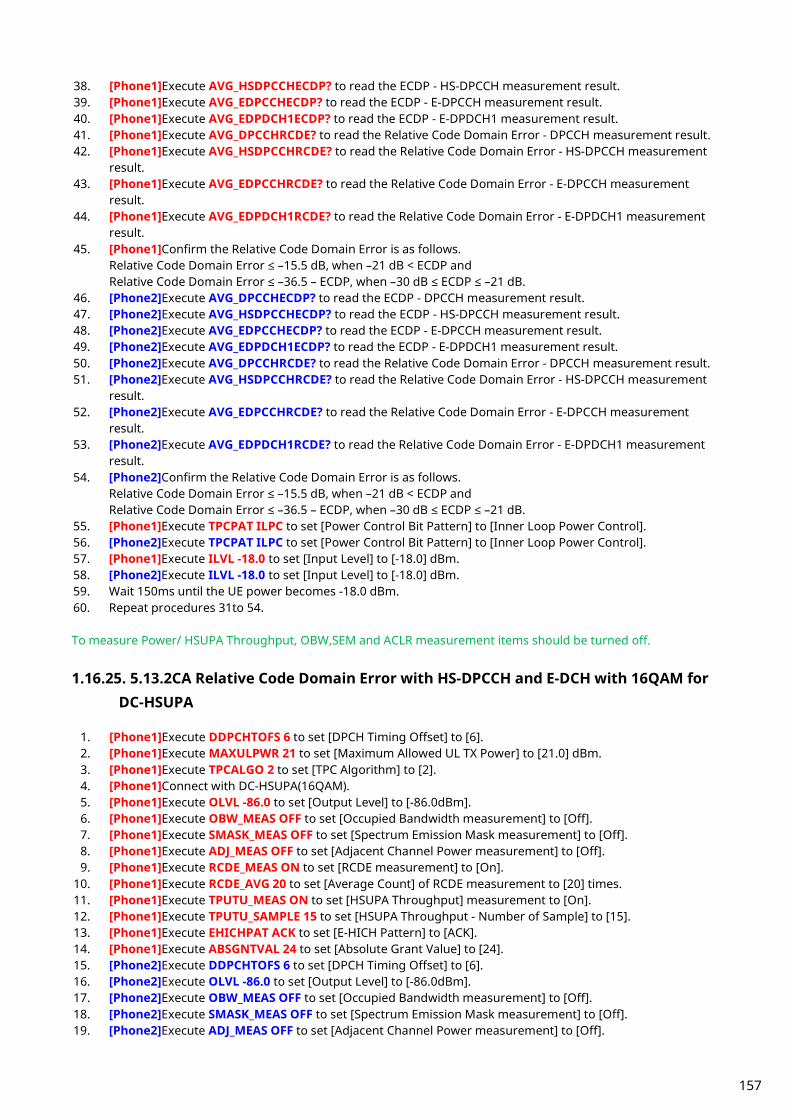
38. [Phone1]Execute AVG_HSDPCCHECDP? to read the ECDP - HS-DPCCH measurement result. 39. [Phone1]Execute AVG_EDPCCHECDP? to read the ECDP - E-DPCCH measurement result. 40. [Phone1]Execute AVG_EDPDCH1ECDP? to read the ECDP - E-DPDCH1 measurement result. 41. [Phone1]Execute AVG_DPCCHRCDE? to read the Relative Code Domain Error - DPCCH measurement result. 42. [Phone1]Execute AVG_HSDPCCHRCDE? to read the Relative Code Domain Error - HS-DPCCH measurement
result. 43. [Phone1]Execute AVG_EDPCCHRCDE? to read the Relative Code Domain Error - E-DPCCH measurement
result. 44. [Phone1]Execute AVG_EDPDCH1RCDE? to read the Relative Code Domain Error - E-DPDCH1 measurement
result. 45. [Phone1]Confirm the Relative Code Domain Error is as follows.
Relative Code Domain Error ≤ –15.5 dB, when –21 dB < ECDP and Relative Code Domain Error ≤ –36.5 – ECDP, when –30 dB ≤ ECDP ≤ –21 dB.
46. [Phone2]Execute AVG_DPCCHECDP? to read the ECDP - DPCCH measurement result. 47. [Phone2]Execute AVG_HSDPCCHECDP? to read the ECDP - HS-DPCCH measurement result. 48. [Phone2]Execute AVG_EDPCCHECDP? to read the ECDP - E-DPCCH measurement result. 49. [Phone2]Execute AVG_EDPDCH1ECDP? to read the ECDP - E-DPDCH1 measurement result. 50. [Phone2]Execute AVG_DPCCHRCDE? to read the Relative Code Domain Error - DPCCH measurement result. 51. [Phone2]Execute AVG_HSDPCCHRCDE? to read the Relative Code Domain Error - HS-DPCCH measurement
result. 52. [Phone2]Execute AVG_EDPCCHRCDE? to read the Relative Code Domain Error - E-DPCCH measurement
result. 53. [Phone2]Execute AVG_EDPDCH1RCDE? to read the Relative Code Domain Error - E-DPDCH1 measurement
result. 54. [Phone2]Confirm the Relative Code Domain Error is as follows.
Relative Code Domain Error ≤ –15.5 dB, when –21 dB < ECDP and Relative Code Domain Error ≤ –36.5 – ECDP, when –30 dB ≤ ECDP ≤ –21 dB.
55. [Phone1]Execute TPCPAT ILPC to set [Power Control Bit Pattern] to [Inner Loop Power Control]. 56. [Phone2]Execute TPCPAT ILPC to set [Power Control Bit Pattern] to [Inner Loop Power Control]. 57. [Phone1]Execute ILVL -18.0 to set [Input Level] to [-18.0] dBm. 58. [Phone2]Execute ILVL -18.0 to set [Input Level] to [-18.0] dBm. 59. Wait 150ms until the UE power becomes -18.0 dBm. 60. Repeat procedures 31to 54.
To measure Power/ HSUPA Throughput, OBW,SEM and ACLR measurement items should be turned off.
1.16.25. 5.13.2CA Relative Code Domain Error with HS-DPCCH and E-DCH with 16QAM for DC-HSUPA
1. [Phone1]Execute DDPCHTOFS 6 to set [DPCH Timing Offset] to [6]. 2. [Phone1]Execute MAXULPWR 21 to set [Maximum Allowed UL TX Power] to [21.0] dBm. 3. [Phone1]Execute TPCALGO 2 to set [TPC Algorithm] to [2]. 4. [Phone1]Connect with DC-HSUPA(16QAM). 5. [Phone1]Execute OLVL -86.0 to set [Output Level] to [-86.0dBm]. 6. [Phone1]Execute OBW_MEAS OFF to set [Occupied Bandwidth measurement] to [Off]. 7. [Phone1]Execute SMASK_MEAS OFF to set [Spectrum Emission Mask measurement] to [Off]. 8. [Phone1]Execute ADJ_MEAS OFF to set [Adjacent Channel Power measurement] to [Off]. 9. [Phone1]Execute RCDE_MEAS ON to set [RCDE measurement] to [On].
10. [Phone1]Execute RCDE_AVG 20 to set [Average Count] of RCDE measurement to [20] times. 11. [Phone1]Execute TPUTU_MEAS ON to set [HSUPA Throughput] measurement to [On]. 12. [Phone1]Execute TPUTU_SAMPLE 15 to set [HSUPA Throughput - Number of Sample] to [15]. 13. [Phone1]Execute EHICHPAT ACK to set [E-HICH Pattern] to [ACK]. 14. [Phone1]Execute ABSGNTVAL 24 to set [Absolute Grant Value] to [24]. 15. [Phone2]Execute DDPCHTOFS 6 to set [DPCH Timing Offset] to [6]. 16. [Phone2]Execute OLVL -86.0 to set [Output Level] to [-86.0dBm]. 17. [Phone2]Execute OBW_MEAS OFF to set [Occupied Bandwidth measurement] to [Off]. 18. [Phone2]Execute SMASK_MEAS OFF to set [Spectrum Emission Mask measurement] to [Off]. 19. [Phone2]Execute ADJ_MEAS OFF to set [Adjacent Channel Power measurement] to [Off].
157

20. [Phone2]Execute RCDE_MEAS ON to set [RCDE measurement] to [On]. 21. [Phone2]Execute RCDE_AVG 20 to set [Average Count] of RCDE measurement to [20] times. 22. [Phone2]Execute TPUTU_MEAS ON to set [HSUPA Throughput] measurement to [On]. 23. [Phone2]Execute TPUTU_SAMPLE 15 to set [HSUPA Throughput - Number of Sample] to [15]. 24. [Phone2]Execute EHICHPAT ACK to set [E-HICH Pattern] to [ACK]. 25. [Phone2]Execute ABSGNTVAL 24 to set [Absolute Grant Value] to [24]. 26. [Phone1]Execute TPCPAT ILPC to set [Power Control Bit Pattern] to [Inner Loop Power Control]. 27. [Phone2]Execute TPCPAT ILPC to set [Power Control Bit Pattern] to [Inner Loop Power Control]. 28. [Phone1]Execute ILVL 15.0 to set [Input Level] to [+15.0] dBm. 29. [Phone2]Execute ILVL 15.0 to set [Input Level] to [+15.0] dBm. 30. Wait 150ms until the UE power becomes 15.0 dBm. 31. [Phone1]Execute TPCPAT ALT to set [Power Control Bit Pattern] to [Alternate]. 32. [Phone1]Execute SWP to perform HSUPA Throughput measurement and RCDE measurement. 33. [Phone1]Execute AVG_ETFCI? to read the E-TFCI measurement result, and confirm it is 67. 34. [Phone2]Execute TPCPAT ALT to set [Power Control Bit Pattern] to [Alternate]. 35. [Phone2]Execute SWP to perform HSUPA Throughput measurement and RCDE measurement. 36. [Phone2]Execute AVG_ETFCI? to read the E-TFCI measurement result, and confirm it is 67. 37. [Phone1]Execute AVG_DPCCHECDP? to read the ECDP - DPCCH measurement result. 38. [Phone1]Execute AVG_HSDPCCHECDP? to read the ECDP - HS-DPCCH measurement result. 39. [Phone1]Execute AVG_EDPCCHECDP? to read the ECDP - E-DPCCH measurement result. 40. [Phone1]Execute AVG_EDPDCH1ECDP? to read the ECDP - E-DPDCH1 measurement result. 41. [Phone1]Execute AVG_DPCCHRCDE? to read the Relative Code Domain Error - DPCCH measurement result. 42. [Phone1]Execute AVG_HSDPCCHRCDE? to read the Relative Code Domain Error - HS-DPCCH measurement
result. 43. [Phone1]Execute AVG_EDPCCHRCDE? to read the Relative Code Domain Error - E-DPCCH measurement
result. 44. [Phone1]Execute AVG_EDPDCH1RCDE? to read the Relative Code Domain Error - E-DPDCH1 measurement
result. 45. [Phone1]Confirm the Relative Code Domain Error is as follows.
Relative Code Domain Error ≤ –17.5 dB, when –25.5 dB < ECDP and Relative Code Domain Error ≤ –43.0 – ECDP, when –30 dB ≤ ECDP ≤ –25.5 dB.
46. [Phone2]Execute AVG_DPCCHECDP? to read the ECDP - DPCCH measurement result. 47. [Phone2]Execute AVG_HSDPCCHECDP? to read the ECDP - HS-DPCCH measurement result. 48. [Phone2]Execute AVG_EDPCCHECDP? to read the ECDP - E-DPCCH measurement result. 49. [Phone2]Execute AVG_EDPDCH1ECDP? to read the ECDP - E-DPDCH1 measurement result. 50. [Phone2]Execute AVG_DPCCHRCDE? to read the Relative Code Domain Error - DPCCH measurement result. 51. [Phone2]Execute AVG_HSDPCCHRCDE? to read the Relative Code Domain Error - HS-DPCCH measurement
result. 52. [Phone2]Execute AVG_EDPCCHRCDE? to read the Relative Code Domain Error - E-DPCCH measurement
result. 53. [Phone2]Execute AVG_EDPDCH1RCDE? to read the Relative Code Domain Error - E-DPDCH1 measurement
result. 54. [Phone2]Confirm the Relative Code Domain Error is as follows.
Relative Code Domain Error ≤ –17.5 dB, when –25.5 dB < ECDP and Relative Code Domain Error ≤ –43.0 – ECDP, when –30 dB ≤ ECDP ≤ –25.5 dB.
55. [Phone1]Execute TPCPAT ILPC to set [Power Control Bit Pattern] to [Inner Loop Power Control]. 56. [Phone2]Execute TPCPAT ILPC to set [Power Control Bit Pattern] to [Inner Loop Power Control]. 57. [Phone1]Execute ILVL -18.0 to set [Input Level] to [-18.0] dBm. 58. [Phone2]Execute ILVL -18.0 to set [Input Level] to [-18.0] dBm. 59. Wait 150ms until the UE power becomes -18.0 dBm. 60. Repeat procedures 31to 54. To measure Power/ HSUPA Throughput, OBW,SEM and ACLR measurement items should be turned off.
158
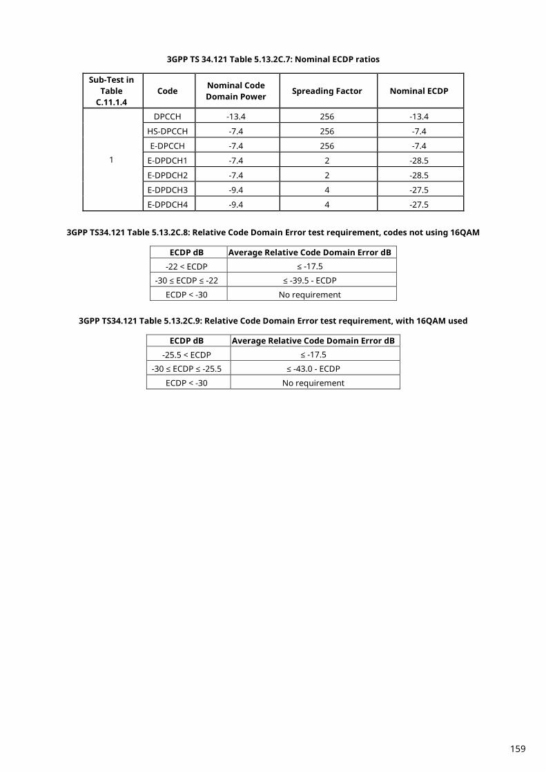
3GPP TS 34.121 Table 5.13.2C.7: Nominal ECDP ratios
Sub-Test in Table
C.11.1.4 Code Nominal Code
Domain Power Spreading Factor Nominal ECDP
1
DPCCH -13.4 256 -13.4
HS-DPCCH -7.4 256 -7.4
E-DPCCH -7.4 256 -7.4
E-DPDCH1 -7.4 2 -28.5
E-DPDCH2 -7.4 2 -28.5
E-DPDCH3 -9.4 4 -27.5
E-DPDCH4 -9.4 4 -27.5
3GPP TS34.121 Table 5.13.2C.8: Relative Code Domain Error test requirement, codes not using 16QAM
ECDP dB Average Relative Code Domain Error dB
-22 < ECDP ≤ -17.5
-30 ≤ ECDP ≤ -22 ≤ -39.5 - ECDP
ECDP < -30 No requirement
3GPP TS34.121 Table 5.13.2C.9: Relative Code Domain Error test requirement, with 16QAM used
ECDP dB Average Relative Code Domain Error dB
-25.5 < ECDP ≤ -17.5
-30 ≤ ECDP ≤ -25.5 ≤ -43.0 - ECDP
ECDP < -30 No requirement
159

1.16.26. 5.13.5 In-band emission for DC-HSUPA
To connect with DC-HSUPA(QPSK), see 1.16.2 Connection with DC-HSUPA(QPSK).
[Sub-test 1]
1. [Phone1]Execute DDPCHTOFS 6 to set [DPCH Timing Offset] to [6]. 2. [Phone1]Execute MAXULPWR 21 to set [Maximum Allowed UL TX Power] to [21.0] dBm. 3. [Phone1]Execute TPCALGO 1 to set [TPC Algorithm] to [1]. 4. [Phone1]Connect with DC-HSUPA(QPSK). 5. [Phone1]Execute OLVL -86.0 to set [Output Level] to [-86.0dBm]. 6. [Phone1]Execute OBW_MEAS OFF to set [Occupied Bandwidth measurement] to [Off]. 7. [Phone1]Execute SMASK_MEAS OFF to set [Spectrum Emission Mask measurement] to [Off]. 8. [Phone1]Execute ADJ_MEAS OFF to set [Adjacent Channel Power measurement] to [Off]. 9. [Phone1]Execute PWR_MEAS ON to set [Power measurement] to [On].
10. [Phone1]Execute PWR_AVG 20 to set [Average Count] of Power measurement to [20] times. 11. [Phone1]Execute EHICHPAT ACK to set [E-HICH Pattern] to [ACK]. 12. [Phone1]Execute ABSGNTVAL 6 to set [Absolute Grant Value] to [6]. 13. [Phone2]Execute DDPCHTOFS 6 to set [DPCH Timing Offset] to [6]. 14. [Phone2]Execute OLVL -86.0 to set [Output Level] to [-86.0dBm]. 15. [Phone2]Execute EHICHPAT ACK to set [E-HICH Pattern] to [ACK]. 16. [Phone2]Execute ABSGNTVAL 6 to set [Absolute Grant Value] to [6]. 17. [Phone1]Execute ILVL 35.0 to set [Input Level] to [+35.0] dBm. 18. [Phone2]Execute ILVL -30.0 to set [Input Level] to [-30.0] dBm. 19. [Phone1]Execute TPCPAT ALL1 to set [Power Control Bit Pattern] to [All1]. 20. [Phone2]Execute TPCPAT ALL0 to set [Power Control Bit Pattern] to [All0]. 21. Wait 150ms until each uplink power reaches Maximum Power and Minimum Power. 22. [Phone1]Execute SWP to perform Power measurement. 23. [Phone1]Execute AVG_FILTPWR? to read the Power measurement result as Power1. 24. [Phone1]Execute AVG_FILTPWR_S? to read the Power measurement result as Power2.
Confirm the measurement result (above Power2-Power1) is lower than -23.2 dB.
160

[Sub-test 2]
1. [Phone1]Execute DDPCHTOFS 6 to set [DPCH Timing Offset] to [6]. 2. [Phone1]Execute MAXULPWR 21 to set [Maximum Allowed UL TX Power] to [21.0] dBm. 3. [Phone1]Execute TPCALGO 1 to set [TPC Algorithm] to [1]. 4. [Phone1]Connect with DC-HSUPA(QPSK). 5. [Phone1]Execute OLVL -86.0 to set [Output Level] to [-86.0dBm]. 6. [Phone1]Execute OBW_MEAS OFF to set [Occupied Bandwidth measurement] to [Off]. 7. [Phone1]Execute SMASK_MEAS OFF to set [Spectrum Emission Mask measurement] to [Off]. 8. [Phone1]Execute ADJ_MEAS OFF to set [Adjacent Channel Power measurement] to [Off]. 9. [Phone1]Execute PWR_MEAS ON to set [Power measurement] to [On].
10. [Phone1]Execute PWR_AVG 20 to set [Average Count] of Power measurement to [20] times. 11. [Phone1]Execute EHICHPAT ACK to set [E-HICH Pattern] to [ACK]. 12. [Phone1]Execute ABSGNTVAL 6 to set [Absolute Grant Value] to [6]. 13. [Phone2]Execute DDPCHTOFS 6 to set [DPCH Timing Offset] to [6]. 14. [Phone2]Execute OLVL -86.0 to set [Output Level] to [-86.0dBm]. 15. [Phone2]Execute EHICHPAT ACK to set [E-HICH Pattern] to [ACK]. 16. [Phone2]Execute ABSGNTVAL 6 to set [Absolute Grant Value] to [6]. 17. [Phone1]Execute ILVL -30.0 to set [Input Level] to [-30.0] dBm. 18. [Phone2]Execute ILVL 35.0 to set [Input Level] to [+35.0] dBm. 19. [Phone1]Execute TPCPAT ALL0 to set [Power Control Bit Pattern] to [All0]. 20. [Phone2]Execute TPCPAT ALL1 to set [Power Control Bit Pattern] to [All1]. 21. Wait 150 ms until each uplink power reaches Maximum Power and Minimum Power. 22. [Phone1]Execute SWP to perform Power measurement. 23. [Phone1]Execute AVG_FILTPWR_S? to read the Power measurement result as Power1. 24. [Phone1]Execute AVG_FILTPWR? to read the Power measurement result as Power2.
Confirm the measurement result (above Power2-Power1) is lower than -23.2 dB.
To measure Power, OBW,SEM and ACLR measurement items should be turned off.
161
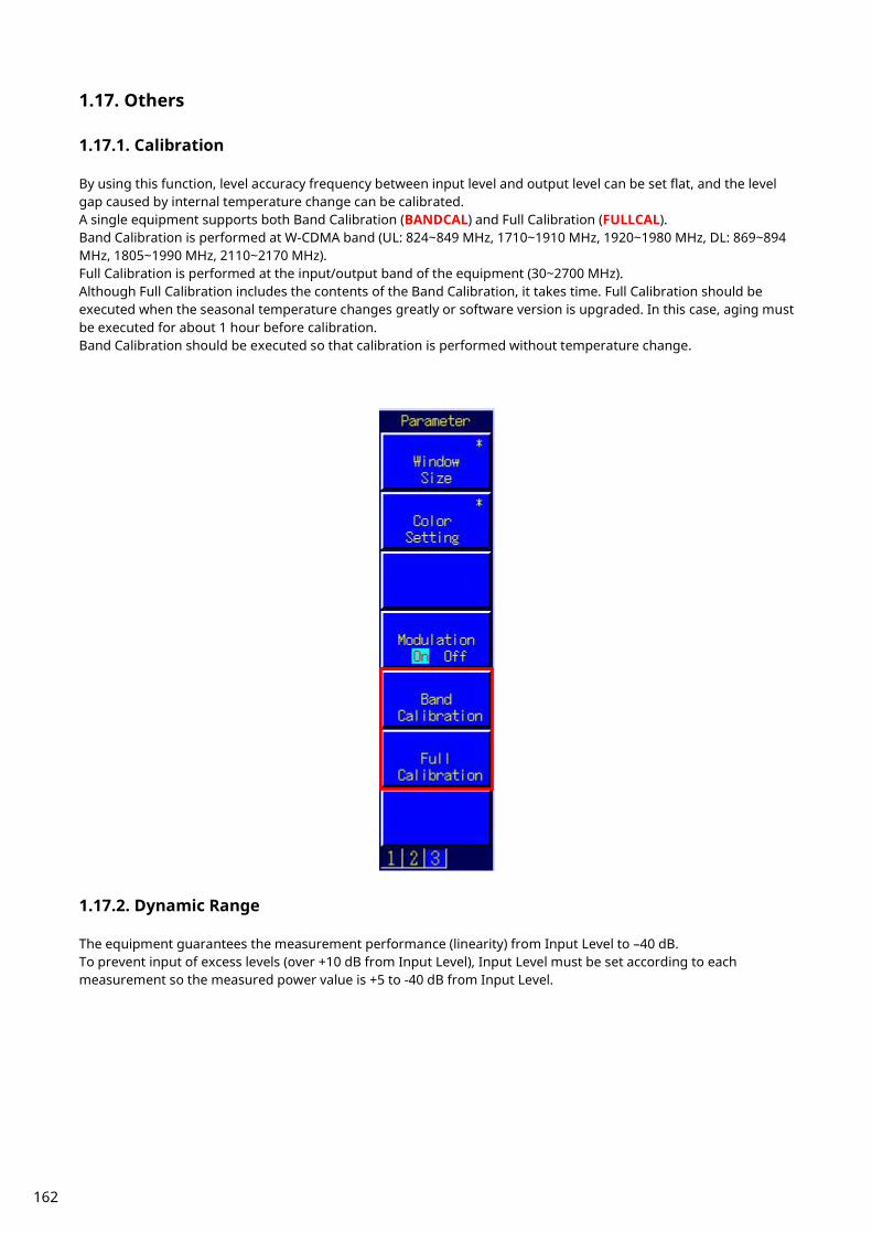
1.17. Others
1.17.1. Calibration By using this function, level accuracy frequency between input level and output level can be set flat, and the level gap caused by internal temperature change can be calibrated. A single equipment supports both Band Calibration (BANDCAL) and Full Calibration (FULLCAL). Band Calibration is performed at W-CDMA band (UL: 824~849 MHz, 1710~1910 MHz, 1920~1980 MHz, DL: 869~894 MHz, 1805~1990 MHz, 2110~2170 MHz). Full Calibration is performed at the input/output band of the equipment (30~2700 MHz). Although Full Calibration includes the contents of the Band Calibration, it takes time. Full Calibration should be executed when the seasonal temperature changes greatly or software version is upgraded. In this case, aging must be executed for about 1 hour before calibration. Band Calibration should be executed so that calibration is performed without temperature change.
1.17.2. Dynamic Range The equipment guarantees the measurement performance (linearity) from Input Level to –40 dB. To prevent input of excess levels (over +10 dB from Input Level), Input Level must be set according to each measurement so the measured power value is +5 to -40 dB from Input Level.
162

1.17.3. External Loss The equipment supports setting of External Loss (such as cable loss) as offset values. External Loss is set at Main DL, Main UL and Aux.
An example of how to set Main DL Loss to 3.0 dB and Main UL Loss to 5.0 dB is shown below.
1. Execute DLEXTLOSSSW ON to set [External Loss(Main DL)] to [On]. 2. Execute ULEXTLOSSW ON to set [External Loss(Main UL)] to [On]. 3. Execute DLEXTLOSS 3.0 to set [External Loss(Main DL)] to [3.0] dB. 4. Execute ULEXTLOSS 5.0 to set [External Loss(Main UL)] to [5.0] dB.
Although the above commands can set only one loss value for all frequencies, up to 100 loss values can be set by using the GPIB and by setting an External Loss Table, which supports both W-CDMA and GSM. In this case, a frequency without a loss value is the table is compensated with next loss value. An example of how to set a 3.0 dB loss value for the 2140 MHz frequency, and a 5.0 dB loss value for the 1950 MHz frequency is shown below.
1. Execute DLEXTLOSSW COMMON to use the Main DL External Loss common table. 2. Execute ULEXTLOSSW COMMON to use the Main UL External Loss common table. 3. Execute LOSSTBLVAL 1950MHz, 0.0, 5.0, 0.0 to set the 1950 MHz Main UL Loss value to 5.0 dB. 4. Execute LOSSTBLVAL 2140MHz, 3.0, 0.0, 0.0 to set the 2140 MHz Main DL Loss value to 3.0 dB.
The number of frequency points specified in the table is displayed either in the on-screen External Loss Table, or can be read by executing LOSSTBLSAMPLE?. All loss values can be deleted by executing DELLOSSTBL. *The operation when setting External Loss differs according to the version. Sometimes, the I/O level may be changed unexpectedly when setting parameters at tracking operation. After setting the measurement conditions (external loss, frequency, etc.), always set the I/O level before starting measurement (W/G, TDS only) The specifications have been changed for version V20.00 and later so the I/O level does not change when changing the external loss and frequency settings.
163
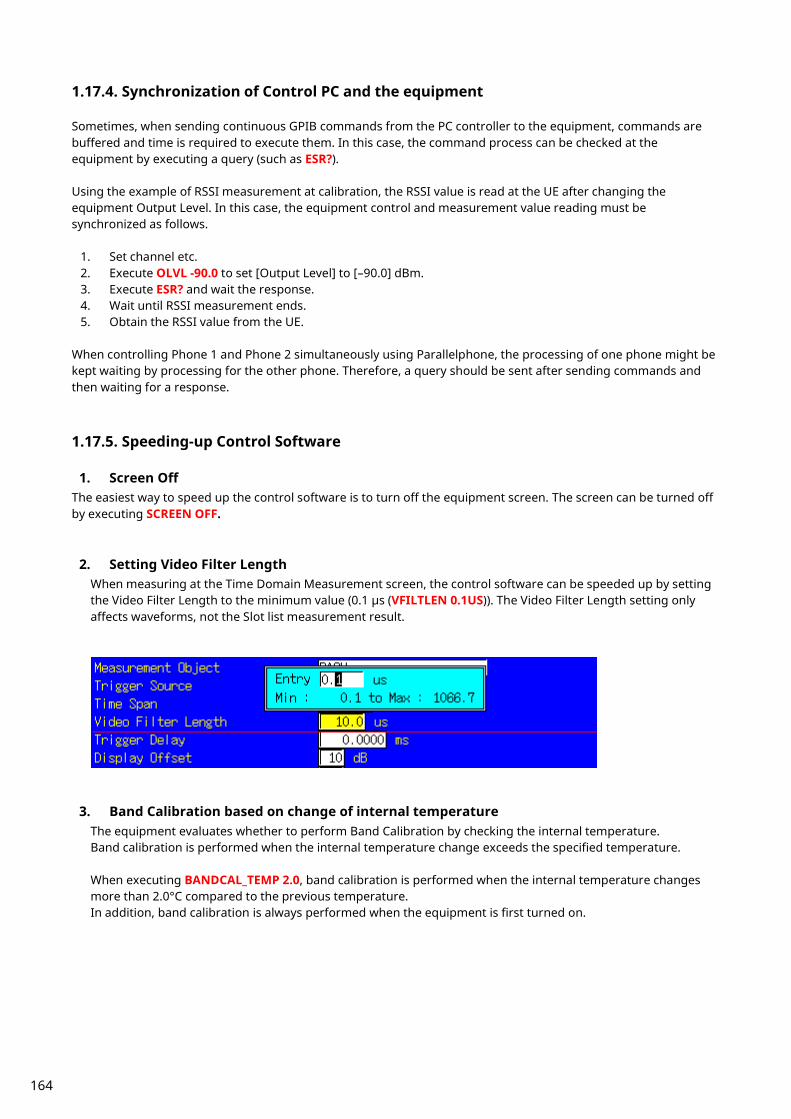
1.17.4. Synchronization of Control PC and the equipment Sometimes, when sending continuous GPIB commands from the PC controller to the equipment, commands are buffered and time is required to execute them. In this case, the command process can be checked at the equipment by executing a query (such as ESR?). Using the example of RSSI measurement at calibration, the RSSI value is read at the UE after changing the equipment Output Level. In this case, the equipment control and measurement value reading must be synchronized as follows.
1. Set channel etc. 2. Execute OLVL -90.0 to set [Output Level] to [–90.0] dBm. 3. Execute ESR? and wait the response. 4. Wait until RSSI measurement ends. 5. Obtain the RSSI value from the UE.
When controlling Phone 1 and Phone 2 simultaneously using Parallelphone, the processing of one phone might be kept waiting by processing for the other phone. Therefore, a query should be sent after sending commands and then waiting for a response.
1.17.5. Speeding-up Control Software
1. Screen Off The easiest way to speed up the control software is to turn off the equipment screen. The screen can be turned off by executing SCREEN OFF.
2. Setting Video Filter Length When measuring at the Time Domain Measurement screen, the control software can be speeded up by setting the Video Filter Length to the minimum value (0.1 µs (VFILTLEN 0.1US)). The Video Filter Length setting only affects waveforms, not the Slot list measurement result.
3. Band Calibration based on change of internal temperature The equipment evaluates whether to perform Band Calibration by checking the internal temperature. Band calibration is performed when the internal temperature change exceeds the specified temperature. When executing BANDCAL_TEMP 2.0, band calibration is performed when the internal temperature changes more than 2.0°C compared to the previous temperature. In addition, band calibration is always performed when the equipment is first turned on.
164

2. GSM Measurement Software
2.1. Specification 2.1.1. MT8820B/20C software specification
Table 2.1.1-1 Specifications for MX882001C GSM Measurement Software
Item Specifications
Electrical characteristics
Typical values (typ.) are only for reference and are not guaranteed.
Frequency/ Modulation measurement
Frequency 300 to 2700 MHz Input level –30 to +40 dBm
(Average power in bursts, Main connector) Carrier frequency accuracy
±(Set frequency × Reference oscillator accuracy + 10 Hz), (when measuring Normal Burst)
±(Set frequency × Reference oscillator accuracy + 20 Hz), (when measuring RACH)
Residual phase error ≤0.5° (rms), 2° (peak) Measurement object Normal Burst, RACH
Amplitude measurement
Frequency 300 to 2700 MHz Input level –30 to +40 dBm
(Average power in bursts, Main connector) Measurement accuracy MT8820B/15B
±0.5 dB (–20 to +40 dBm), ±0.7 dB (–30 to –20 dBm), after calibration
MT8820C ±0.5 dB (–20 to +40 dBm), typ. ±0.3 dB (–20 to +40 dBm), ±0.7 dB (–30 to –20 dBm) after calibration, 10 to 40°C
Linearity ±0.2 dB (–40 to 0 dB, ≥–30 dBm) Measurement range of power when Carrier off
≥65 dB (≥–10 dBm), ≥45 dB (≥–30 to –10 dBm)
Burst wave view Rise, Fall, Slot, On-interval Measurement object Normal Burst, RACH
165
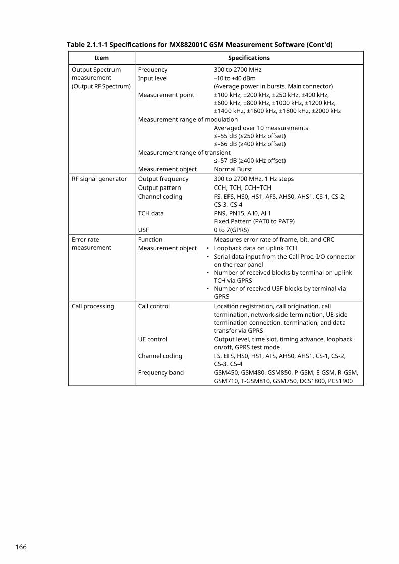
Table 2.1.1-1 Specifications for MX882001C GSM Measurement Software (Cont'd)
Item Specifications
Output Spectrum measurement (Output RF Spectrum)
Frequency 300 to 2700 MHz Input level –10 to +40 dBm
(Average power in bursts, Main connector) Measurement point ±100 kHz, ±200 kHz, ±250 kHz, ±400 kHz,
±600 kHz, ±800 kHz, ±1000 kHz, ±1200 kHz, ±1400 kHz, ±1600 kHz, ±1800 kHz, ±2000 kHz
Measurement range of modulation Averaged over 10 measurements ≤–55 dB (≤250 kHz offset) ≤–66 dB (≥400 kHz offset)
Measurement range of transient ≤–57 dB (≥400 kHz offset)
Measurement object Normal Burst RF signal generator Output frequency 300 to 2700 MHz, 1 Hz steps
Output pattern CCH, TCH, CCH+TCH Channel coding FS, EFS, HS0, HS1, AFS, AHS0, AHS1, CS-1, CS-2,
CS-3, CS-4 TCH data PN9, PN15, All0, All1
Fixed Pattern (PAT0 to PAT9) USF 0 to 7(GPRS)
Error rate measurement
Function Measures error rate of frame, bit, and CRC Measurement object • Loopback data on uplink TCH • Serial data input from the Call Proc. I/O connector
on the rear panel • Number of received blocks by terminal on uplink
TCH via GPRS • Number of received USF blocks by terminal via
GPRS Call processing Call control Location registration, call origination, call
termination, network-side termination, UE-side termination connection, termination, and data transfer via GPRS
UE control Output level, time slot, timing advance, loopback on/off, GPRS test mode
Channel coding FS, EFS, HS0, HS1, AFS, AHS0, AHS1, CS-1, CS-2, CS-3, CS-4
Frequency band GSM450, GSM480, GSM850, P-GSM, E-GSM, R-GSM, GSM710, T-GSM810, GSM750, DCS1800, PCS1900
166

Table 2.1.1-2 Specifications for MX882001C-001 GSM Voice Codec
Item Specifications
Function End-to-end communications test between a handset connected to the MT8820C and UE. Encode the voice from Audio Input, Output the decoded voice to AF Output. Encode the tone signal and Output the tone signal to AF Output. Measure the voice signal from AF Input and decoded voice signal.
Voice codec GSM_EFR, GSM_AMR Codec level control Encoder input gain –3.00 to +3.00 dB, 0.01 dB steps
Handset microphone volume 0, 1, 2, 3, 4, 5
Handset speaker volume 0, 1, 2, 3, 4, 5
AF output Frequency range 30 Hz to 10 kHz, Resolution 1 Hz Accuracy ±(Set frequency × Reference oscillator accuracy +
0.1 Hz) Level setting range 0 to 5 V peak (AF Output connector) Setting resolution 1 mV (≤5 V peak),
100 µV (≤500 mV peak), 10 µV (≤50 mV peak)
Accuracy ±0.2 dB (≥10 mV peak, ≥50 Hz), ±0.3 dB (≥10 mV peak, <50 Hz)
Waveform distortion ≤–60 dB (≥500 mV peak, ≤5 kHz), ≤–54 dB (≥70 mV peak)
Output impedance ≤1 Ω Max. output current 100 mA
AF input Frequency range 50 Hz to 10 kHz Input level range 1 mV peak to 5 V peak (AF Input connector) Maximum input level 30 V rms Input impedance 100 kΩ Frequency measurement accuracy
± (Reference oscillator accuracy + 0.5 Hz) Level measurement accuracy
±0.2 dB (≥10 mV peak), ±0.4 dB (≥1 mV peak, ≥1 kHz)
SINAD measurement Frequency at 1 kHz ≥60 dB (≥1000 mV peak), ≥54 dB (>50 mV peak), ≥46 dB (≥10 mV peak)
Distortion measurement Frequency at 1 kHz ≤–60 dB (≥1000 mV peak), ≤–54 dB (>50 mV peak), ≤–46 dB (≥10 mV peak)
167

Table 2.1.1-3 Specifications for MX882001C-002 GSM External Packet Data
Item Specifications
Function Transferring the packet data between UE and a server connecting to Ethernet port (10BT) on the MT8820C.
Channel coding CS-1, CS-2, CS-3, CS-4
Table 2.1.1-4 Specifications for MX882001C-005 GSM A-GPS
Item Specifications
Function A-GPS tests defined in the 3GPP specifications
Table 2.1.1-5 Specifications for MX882001C-011 EGPRS Measurement Software
Item Specifications
Function This can be used to measure the performance (Tx, Rx) of UE for EGPRS. Electrical characteristics
Typical values (typ.) are only for reference and are not guaranteed.
Frequency/Modulation measurement
Frequency Same as MX882001C Input level Same as MX882001C Carrier frequency accuracy
Same as MX882001C Residual phase error Same as MX882001C Residual EVM (8PSK) ≤1.5% (rms) Measurement object Normal Burst (GMSK, 8PSK), RACH
Amplitude measurement
Frequency Same as MX882001C Input level Same as MX882001C Measurement accuracy Same as MX882001C Linearity Same as MX882001C Measurement range of power when Carrier off
Same as MX882001C Burst wave view Same as MX882001C Measurement object Normal Burst (GMSK, 8PSK), RACH
Output Spectrum measurement (Output RF Spectrum)
Frequency Same as MX882001C Input level Same as MX882001C Measurement point Same as MX882001C Measurement range of modulation
Same as MX882001C Measurement range of transient
Same as MX882001C Measurement object Normal Burst (GMSK, 8PSK)
168

Table 2.1.1-5 Specifications for MX882001C-011 EGPRS Measurement Software (Cont'd)
Item Specifications
RF signal generator Output frequency Same as MX882001C Phase error (GMSK) Same as MX882001C Modulation accuracy (8PSK)
≤3% (rms) Output pattern CCH, TCH, CCH+TCH Coding scheme MCS-1, MCS-2, MCS-3, MCS-4, MCS-5, MCS-6,
MCS-7, MCS-8, MCS-9 Puncturing scheme P1, P2, P3 TCH data PN9, PN15, All0, All1
Fixed pattern (PAT0 to PAT9) Error rate measurement
Function Measures bit error rate. Measurement object • Loopback data on uplink TCH(GMSK, 8PSK) • Number of received blocks by terminal on uplink
TCH via EGPRS • Number of received USF blocks by terminal via
EGPRS Call processing Call control Location registration, connection, termination, and
data transfer via EGPRS UE control Output level, time slot, timing advance, EGPRS test
mode Coding scheme MCS-1, MCS-2, MCS-3, MCS-4, MCS-5, MCS-6,
MCS-7, MCS-8, MCS-9 Puncturing scheme P1, P2, P3
169

2.1.2. MT8821C software specification Table 2.1.2-1 Specifications for MX882101C GSM Measurement Software
Item Specifications
Electrical characteristics
Typical values (typ.) are only for reference and are not guaranteed.
Frequency/Modulation measurement
Frequency 350 to 2700 MHz
For the frequencies below 500 MHz, only the following range meets the specifications:
380.2 to 389.8 MHz (Band T-GSM380)
410.2 to 419.8 MHz (Band T-GSM410)
450.4 to 457.6 MHz (Band GSM450)
478.8 to 486 MHz (Band GSM480)
Input level –30 to +40 dBm (Average power in bursts, Main connector)
Carrier frequency accuracy ±(Set frequency × Reference oscillator accuracy + 10 Hz), (when measuring Normal Burst)
±(Set frequency × Reference oscillator accuracy + 20 Hz), (when measuring RACH)
Residual phase error ≤0.5° (rms), 2° (peak)
Measurement object Normal Burst, RACH
Amplitude measurement
Frequency 350 to 2700 MHz
For the frequencies below 500 MHz, only the following range meets the specifications:
380.2 to 389.8 MHz (Band T-GSM380)
410.2 to 419.8 MHz (Band T-GSM410)
450.4 to 457.6 MHz (Band GSM450)
478.8 to 486 MHz (Band GSM480)
Input level –30 to +40 dBm (Average power in bursts, Main connector)
Measurement accuracy ±0.5 dB (–30 to +40 dBm), typ. ±0.3 dB (–30 to +40 dBm) after calibration, 10 to 40°C
Linearity ±0.2 dB (–40 to 0 dB, ≥–30 dBm)
Measurement range of power when Carrier off ≥65 dB (≥–10 dBm), ≥45 dB (≥–30 to –10 dBm)
Burst wave view Rise, Fall, Slot, On-interval
Measurement object Normal Burst, RACH
170

Table 2.1.2-1 Specifications for MX882101C GSM Measurement Software (Cont'd)
Item Specifications
Output Spectrum measurement
(Output RF Spectrum)
Frequency 350 to 2700 MHz For the frequencies below 500 MHz, only the
following range meets the specifications: 380.2 to 389.8 MHz (Band T-GSM380) 410.2 to 419.8 MHz (Band T-GSM410) 450.4 to 457.6 MHz (Band GSM450) 478.8 to 486 MHz (Band GSM480) Input level –10 to +40 dBm
(Average power in bursts, Main connector)
Measurement point ±100 kHz, ±200 kHz, ±250 kHz, ±400 kHz, ±600 kHz, ±800 kHz, ±1000 kHz, ±1200 kHz, ±1400 kHz, ±1600 kHz, ±1800 kHz, ±2000 kHz
Measurement range of modulation Averaged over 10 measurements ≤–55 dB (≤250 kHz offset) ≤–66 dB (≥400 kHz offset)
Measurement range of transient ≤–57 dB (≥400 kHz offset)
Measurement object Normal Burst
RF signal generator Output frequency 350 to 2700 MHz, 1 Hz steps Output pattern CCH, TCH, CCH+TCH Channel coding FS, EFS, HS0, HS1, AFS, AHS0, AHS1, CS-1, CS-2, CS-3,
CS-4 TCH data PN9, PN15, All0, All1
Fixed Pattern (PAT0 to PAT9) USF 0 to 7 (GPRS)
Error rate measurement
Function Measures error rate of frame, bit, and CRC Measurement object • Loopback data on uplink TCH • Serial data input from the Call Proc. I/O connector
on the rear panel • Number of received blocks by terminal on uplink
TCH via GPRS • Number of received USF blocks by terminal via GPRS
Call processing Call control Location registration, call origination, call termination, network-side termination, UE-side termination connection, termination, and data transfer via GPRS
UE control Output level, time slot, timing advance, loopback on/off, GPRS test mode
Channel coding FS, EFS, HS0, HS1, AFS, AHS, CS-1, CS-2, CS-3, CS-4
Frequency band GSM450, GSM480, GSM850, P-GSM, E-GSM, R-GSM, GSM710, T-GSM810, GSM750, DCS1800, PCS1900
171

Table 2.1.2-2 Specifications for MX882101C-001 GSM Voice Codec
Item Specifications
Function End-to-end communications test between a handset connected to the MT8821C and UE. Encode the voice from Audio Input, Output the decoded voice to AF Output. Encode the tone signal and Output the tone signal to AF Output. Measure the voice signal from AF Input and decoded voice signal.
Voice codec GSM_EFR, GSM_AMR
Codec level control Encoder input gain –3.00 to +3.00 dB, 0.01 dB steps
Handset microphone volume 0, 1, 2, 3, 4, 5
Handset speaker volume 0, 1, 2, 3, 4, 5
AF output Frequency range 30 Hz to 10 kHz, Resolution 1 Hz
Accuracy ±(Setting Frequency × Reference oscillator accuracy + 0.1 Hz)
Level setting range 0 to 5 V peak (AF Output connector)
Setting resolution 1 mV (≤5 V peak), 100 µV (≤500 mV peak), 10 µV (≤50 mV peak)
Accuracy ±0.2 dB (≥10 mV peak, ≥50 Hz), ±0.3 dB (≥10 mV peak, <50 Hz)
Waveform distortion ≤–60 dB (≥500 mV peak, ≤5 kHz), ≤–54 dB (≥70 mV peak)
Output impedance ≤1 Ω
Max. output current 100 mA
AF input Frequency range 50 Hz to 10 kHz
Input level range 1 mV peak to 5 V peak (AF Input connector)
Maximum input level 30 V rms
Input impedance 100 kΩ
Frequency measurement accuracy ± (Reference oscillator accuracy + 0.5 Hz)
Level measurement accuracy ±0.2 dB (≥10 mV peak), ±0.4 dB (≥1 mV peak, ≥1 kHz)
SINAD measurement Frequency at 1 kHz ≥60 dB (≥1000 mV peak), ≥54 dB (>50 mV peak), ≥46 dB (≥10 mV peak)
Distortion measurement Frequency at 1 kHz ≤–60 dB (≥1000 mV peak), ≤–54 dB (>50 mV peak), ≤–46 dB (≥10 mV peak)
172

Table 2.1.2-3 Specifications for MX882101C-002 GSM External Packet Data
Item Specifications
Function Transferring the packet data between UE and a server connecting to Ethernet port (10BT) on the MT8821C.
Channel coding CS-1, CS-2, CS-3, CS-4
Table 2.1.2-4 Specifications for MX882101C-005 GSM A-GPS
Item Specifications
Function A-GPS tests defined in the 3GPP specifications
Table 2.1.2-5 Specifications for MX882101C-011 EGPRS Measurement Software
Item Specifications
Function This can be used to measure the performance (Tx, Rx) of UE for EGPRS.
Electrical characteristics
Typical values (typ.) are only for reference and are not guaranteed.
Frequency/Modulation measurement
Frequency Same as MX882101C
Input level Same as MX882101C
Carrier frequency accuracy Same as MX882101C
Residual phase error Same as MX882101C
Residual EVM (8PSK) ≤1.5% (rms)
Measurement object Normal Burst (GMSK, 8PSK), RACH
Amplitude measurement
Frequency Same as MX882101C
Input level Same as MX882101C
Measurement accuracy Same as MX882101C
Linearity Same as MX882101C
Measurement range of power when Carrier off Same as MX882101C
Burst wave view Same as MX882101C
Measurement object Normal Burst (GMSK, 8PSK), RACH
Output Spectrum measurement
(Output RF Spectrum)
Frequency Same as MX882101C
Input level Same as MX882101C
Measurement point Same as MX882101C
Measurement range of modulation Same as MX882101C
Measurement range of transient Same as MX882101C
Measurement object Normal Burst (GMSK, 8PSK)
173
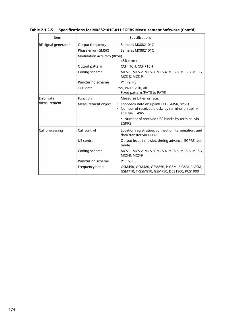
Table 2.1.2-5 Specifications for MX882101C-011 EGPRS Measurement Software (Cont'd)
Item Specifications
RF signal generator Output frequency Same as MX882101C
Phase error (GMSK) Same as MX882101C
Modulation accuracy (8PSK) ≤3% (rms)
Output pattern CCH, TCH, CCH+TCH
Coding scheme MCS-1, MCS-2, MCS-3, MCS-4, MCS-5, MCS-6, MCS-7, MCS-8, MCS-9
Puncturing scheme P1, P2, P3
TCH data PN9, PN15, All0, All1 Fixed pattern (PAT0 to PAT9)
Error rate measurement
Function Measures bit error rate.
Measurement object • Loopback data on uplink TCH(GMSK, 8PSK) • Number of received blocks by terminal on uplink
TCH via EGPRS
• Number of received USF blocks by terminal via EGPRS
Call processing Call control Location registration, connection, termination, and data transfer via EGPRS
UE control Output level, time slot, timing advance, EGPRS test mode
Coding scheme MCS-1, MCS-2, MCS-3, MCS-4, MCS-5, MCS-6, MCS-7, MCS-8, MCS-9
Puncturing scheme P1, P2, P3
Frequency band GSM450, GSM480, GSM850, P-GSM, E-GSM, R-GSM, GSM710, T-GSM810, GSM750, DCS1800, PCS1900
174

2.2. 3GPP Measurement Specification Table
Item Comment
12 Transceiver
12.1 Conducted spurious emissions Requires SPA √
12.2 Radiated spurious emissions Requires SPA √
12.3 Conducted spurious emissions for MS supporting R-GSM frequency
band
Requires SPA √
12.4 Radiated spurious emissions for MS supporting R-GSM frequency
band
Requires SPA √
13 Transmitter
13.1 Frequency error and phase error √√
13.2 Frequency error under multipath and interference conditions Requires Fading Simulator √
13.3 Transmitter output power and burst timing √√
13.4 Output RF spectrum √√
13.6 Frequency error and phase error in HSCSD multi-slot configurations −
13.7 Transmitter output power and burst timing in HSCSD configurations −
13.8 Output RF spectrum in HSCSD multislot configuration −
13.9 Output RF spectrum for MS supporting the R-GSM band √√
13.16 GPRS Transmitter tests
13.16.1 Frequency error and phase error in GPRS multi-slot configuration √√
13.16.2 Transmitter output power in GPRS multi-slot configuration up to 2UL √√
13.16.3 Output RF spectrum in GPRS multi-slot configuration 1UL only √√
13.17 EGPRS Transmitter tests without Call Processing
13.17.1 Frequency error and modulation accuracy in EGPRS configuration √√
13.17.2 Frequency error under multipath and interference conditions Requires Fading Simulator √
13.17.3 EGPRS Transmitter output power up to 2UL √√
13.17.4 Output RF spectrum in EGPRS configuration 1UL only √√
√√: Supported (except Frequency Hopping) | √: Requires external equipment (SPA or SG) | F: Future Support | −: Not Supported
175
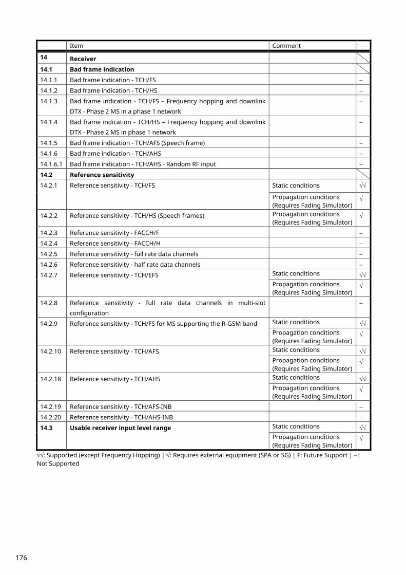
Item Comment
14 Receiver
14.1 Bad frame indication
14.1.1 Bad frame indication - TCH/FS −
14.1.2 Bad frame indication - TCH/HS −
14.1.3 Bad frame indication - TCH/FS – Frequency hopping and downlink
DTX - Phase 2 MS in a phase 1 network
−
14.1.4 Bad frame indication - TCH/HS – Frequency hopping and downlink
DTX - Phase 2 MS in phase 1 network
−
14.1.5 Bad frame indication - TCH/AFS (Speech frame) −
14.1.6 Bad frame indication - TCH/AHS −
14.1.6.1 Bad frame indication - TCH/AHS - Random RF input −
14.2 Reference sensitivity
14.2.1 Reference sensitivity - TCH/FS Static conditions √√
Propagation conditions (Requires Fading Simulator)
√
14.2.2 Reference sensitivity - TCH/HS (Speech frames) Propagation conditions (Requires Fading Simulator)
√
14.2.3 Reference sensitivity - FACCH/F −
14.2.4 Reference sensitivity - FACCH/H −
14.2.5 Reference sensitivity - full rate data channels −
14.2.6 Reference sensitivity - half rate data channels −
14.2.7 Reference sensitivity - TCH/EFS Static conditions √√ Propagation conditions (Requires Fading Simulator)
√
14.2.8 Reference sensitivity - full rate data channels in multi-slot
configuration
−
14.2.9 Reference sensitivity - TCH/FS for MS supporting the R-GSM band Static conditions √√ Propagation conditions (Requires Fading Simulator)
√
14.2.10 Reference sensitivity - TCH/AFS Static conditions √√ Propagation conditions (Requires Fading Simulator)
√
14.2.18 Reference sensitivity - TCH/AHS Static conditions √√ Propagation conditions (Requires Fading Simulator)
√
14.2.19 Reference sensitivity - TCH/AFS-INB −
14.2.20 Reference sensitivity - TCH/AHS-INB −
14.3 Usable receiver input level range Static conditions √√ Propagation conditions (Requires Fading Simulator)
√
√√: Supported (except Frequency Hopping) | √: Requires external equipment (SPA or SG) | F: Future Support | −: Not Supported
176
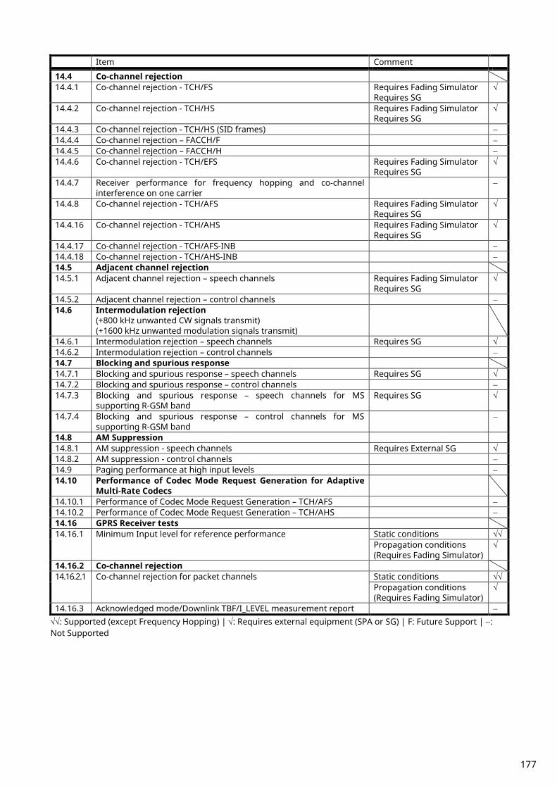
Item Comment
14.4 Co-channel rejection 14.4.1 Co-channel rejection - TCH/FS Requires Fading Simulator
Requires SG √
14.4.2 Co-channel rejection - TCH/HS Requires Fading Simulator Requires SG
√
14.4.3 Co-channel rejection - TCH/HS (SID frames) − 14.4.4 Co-channel rejection – FACCH/F − 14.4.5 Co-channel rejection – FACCH/H − 14.4.6 Co-channel rejection - TCH/EFS Requires Fading Simulator
Requires SG √
14.4.7 Receiver performance for frequency hopping and co-channel interference on one carrier
−
14.4.8 Co-channel rejection - TCH/AFS Requires Fading Simulator Requires SG
√
14.4.16 Co-channel rejection - TCH/AHS Requires Fading Simulator Requires SG
√
14.4.17 Co-channel rejection - TCH/AFS-INB − 14.4.18 Co-channel rejection - TCH/AHS-INB − 14.5 Adjacent channel rejection 14.5.1 Adjacent channel rejection – speech channels Requires Fading Simulator
Requires SG √
14.5.2 Adjacent channel rejection – control channels − 14.6 Intermodulation rejection
(+800 kHz unwanted CW signals transmit) (+1600 kHz unwanted modulation signals transmit)
14.6.1 Intermodulation rejection – speech channels Requires SG √ 14.6.2 Intermodulation rejection – control channels − 14.7 Blocking and spurious response 14.7.1 Blocking and spurious response – speech channels Requires SG √ 14.7.2 Blocking and spurious response – control channels − 14.7.3 Blocking and spurious response – speech channels for MS
supporting R-GSM band Requires SG √
14.7.4 Blocking and spurious response – control channels for MS supporting R-GSM band
−
14.8 AM Suppression 14.8.1 AM suppression - speech channels Requires External SG √ 14.8.2 AM suppression - control channels − 14.9 Paging performance at high input levels − 14.10 Performance of Codec Mode Request Generation for Adaptive
Multi-Rate Codecs
14.10.1 Performance of Codec Mode Request Generation – TCH/AFS − 14.10.2 Performance of Codec Mode Request Generation – TCH/AHS − 14.16 GPRS Receiver tests 14.16.1 Minimum Input level for reference performance Static conditions √√
Propagation conditions (Requires Fading Simulator)
√
14.16.2 Co-channel rejection 14.16.2.1 Co-channel rejection for packet channels Static conditions √√
Propagation conditions (Requires Fading Simulator)
√
14.16.3 Acknowledged mode/Downlink TBF/I_LEVEL measurement report − √√: Supported (except Frequency Hopping) | √: Requires external equipment (SPA or SG) | F: Future Support | −: Not Supported
177
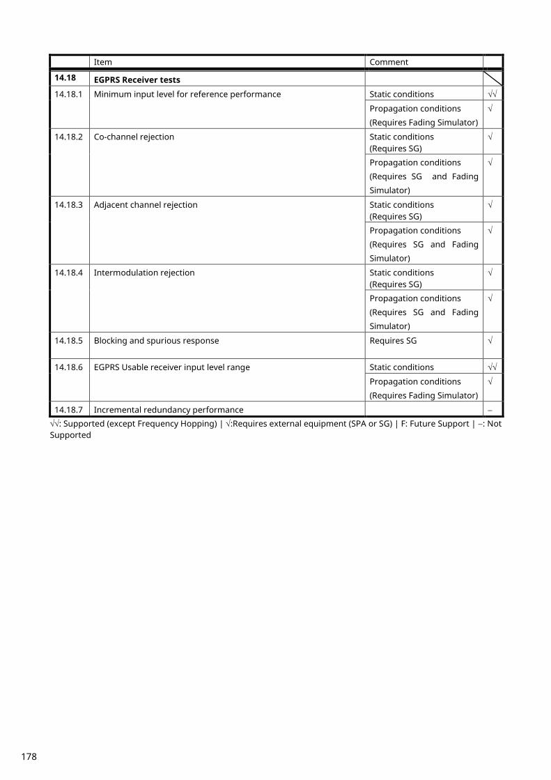
Item Comment
14.18 EGPRS Receiver tests
14.18.1 Minimum input level for reference performance Static conditions √√
Propagation conditions
(Requires Fading Simulator)
√
14.18.2 Co-channel rejection Static conditions (Requires SG)
√
Propagation conditions
(Requires SG and Fading
Simulator)
√
14.18.3 Adjacent channel rejection Static conditions (Requires SG)
√
Propagation conditions
(Requires SG and Fading
Simulator)
√
14.18.4 Intermodulation rejection Static conditions (Requires SG)
√
Propagation conditions
(Requires SG and Fading
Simulator)
√
14.18.5 Blocking and spurious response Requires SG √
14.18.6 EGPRS Usable receiver input level range Static conditions √√
Propagation conditions
(Requires Fading Simulator)
√
14.18.7 Incremental redundancy performance −
√√: Supported (except Frequency Hopping) | √:Requires external equipment (SPA or SG) | F: Future Support | −: Not Supported
178

2.3. TRX Measurement (GSM)
2.3.1. Connection with GSM Measurement is executed after connecting UE in the loopback state. The UE location registration can be stopped by turning on Auto Registration inside the registered network. If location registration is unnecessary, turn on Auto Registration (AUTOREG ON) before turning on the UE power.
1. Execute PRESET to preset parameter. 2. Turn on the UE. 3. Execute CALLRSLT? 4 and wait until it becomes 1,0 (Registration Execute). 4. Execute CALLSTAT? and wait until it becomes1 (= Idle(Regist). 5. Execute CALLSA to connect with Voice Call. 6. Execute CALLSTAT? and wait until it becomes 7 (= Communication). 7. Execute LOOPBACK ON to make UE in Loopback state.
2.3.2. Disconnection from GSM
1. Execute LOOPBACK OFF to set UE to normal connection state. 2. Execute CALLSO to disconnect from Voice Call. 3. Execute CALLSTAT? and wait until it becomes1 (= Idle(Regist)).
2.3.3. Changing TCH Channel and MS Power Level at Handover Usually, Tx/Rx measurement is performed at three frequency points, and Tx measurement is performed with three power levels (L, M, H). In this case, the channel can be quickly switched without reconnection by switching it at handover with a higher output level. When a GPIB command is sent during handover, it waits until handover ends.
1. Execute CHMSPWR 1,5 to change [TCH Channel] to [1] CH, [MS Power Level] to [5]. 2. Perform TRX measurement. 3. Execute CHMSPWR 1,12 to change [TCH Channel] to [1] CH, [MS Power Level] to [12]. 4. Perform TX measurement. 5. Execute CHMSPWR 1,19 to change [TCH Channel] to [1] CH, [MS Power Level] to [19]. 6. Perform TX measurement. 7. Execute CHMSPWR 63,5 to change [TCH Channel] to [63] CH, [MS Power Level] to [5]. 8. Perform TRX measurement. 9. Execute CHMSPWR 63,12 to change [TCH Channel] to [63] CH, [MS Power Level] to [12].
10. Perform TX measurement. 11. Execute CHMSPWR 127,19 to change [TCH Channel] to [63] CH, [MS Power Level] to [19]. 12. Perform TX measurement. 13. Execute CHMSPWR 127,5 to change [TCH Channel] to [127] CH, [MS Power Level] to [5]. 14. Perform TRX measurement. 15. Execute CHMSPWR 127,12 to change [TCH Channel] to [127] CH, [MS Power Level] to [12]. 16. Perform TX measurement. 17. Execute CHMSPWR 127,19 to change [TCH Channel] to [127] CH, [MS Power Level] to [19]. 18. Perform TX measurement.
179
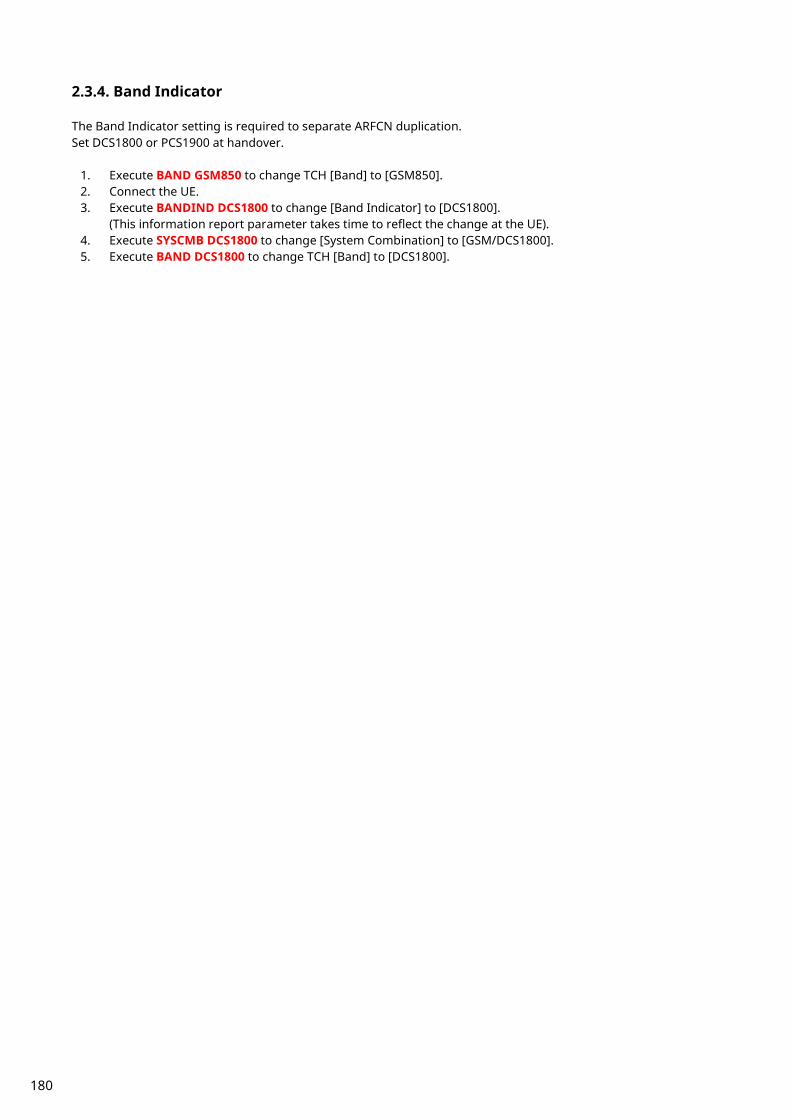
2.3.4. Band Indicator The Band Indicator setting is required to separate ARFCN duplication. Set DCS1800 or PCS1900 at handover.
1. Execute BAND GSM850 to change TCH [Band] to [GSM850]. 2. Connect the UE. 3. Execute BANDIND DCS1800 to change [Band Indicator] to [DCS1800].
(This information report parameter takes time to reflect the change at the UE). 4. Execute SYSCMB DCS1800 to change [System Combination] to [GSM/DCS1800]. 5. Execute BAND DCS1800 to change TCH [Band] to [DCS1800].
180

2.3.5. 13.1 Frequency error and phase error
1. Connect using Loopback. 2. Execute MOD_MEAS ON to set [Modulation Analysis] measurement to [On]. 3. Execute MOD_COUNT 60 to set [Average Count] of Modulation Analysis measurement to [60] times. 4. Execute SWP to perform Modulation Analysis measurement. 5. Execute MAX_CARRFERR? PPM to read the Maximum Frequency Error measurement result. 6. Execute MIN_CARRFERR? PPM to read the Minimum Frequency Error measurement result. 7. Confirm the measurement result is lower than 0.1 ppm. 8. Execute MAX_PHASEERR? to read the RMS Phase Error measurement result. 9. Confirm the measurement result is lower than 5 deg.
10. Execute MAX_PPHASEERR? to read the Peak Phase Error measurement result. 11. Execute MIN_PPHASEERR? to read the Peak Phase Error measurement result. 12. Confirm the measurement result is lower than 20 deg. Use the Max and Min measurement result for measurement with symbols (such as Frequency Error).
181
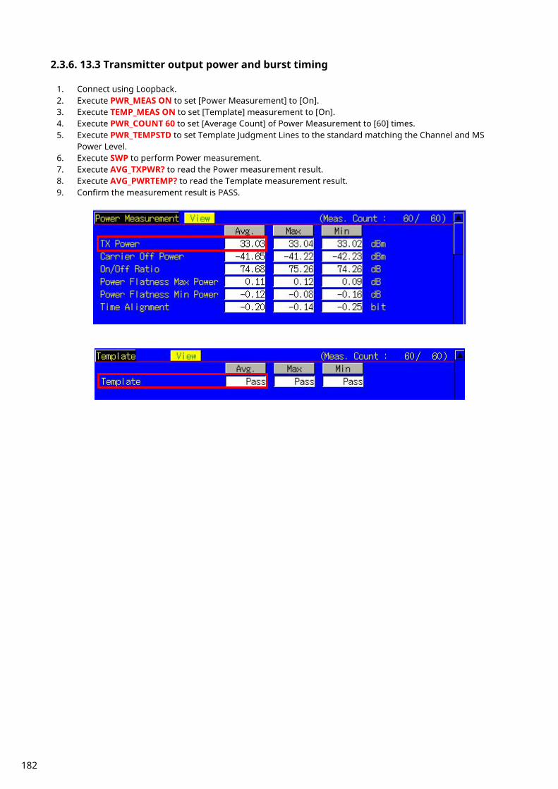
2.3.6. 13.3 Transmitter output power and burst timing
1. Connect using Loopback. 2. Execute PWR_MEAS ON to set [Power Measurement] to [On]. 3. Execute TEMP_MEAS ON to set [Template] measurement to [On]. 4. Execute PWR_COUNT 60 to set [Average Count] of Power Measurement to [60] times. 5. Execute PWR_TEMPSTD to set Template Judgment Lines to the standard matching the Channel and MS
Power Level. 6. Execute SWP to perform Power measurement. 7. Execute AVG_TXPWR? to read the Power measurement result. 8. Execute AVG_PWRTEMP? to read the Template measurement result. 9. Confirm the measurement result is PASS.
182

2.3.7. 13.4 Output RF spectrum
1. Connect using Loopback. 2. Execute ORFSMD_MEAS ON to set [Output RF Spectrum - Modulation] measurement to [On]. 3. Execute ORFSSW_MEAS ON to set [Output RF Spectrum - Switching] measurement to [On]. 4. Execute ORFSMD_COUNT 60 to set [Average Count] of Output RF Spectrum - Modulation measurement to
[60] times. 5. Execute ORFSSW_COUNT 60 to set [Average Count] of Output RF Spectrum - Switching measurement to [60]
times. 6. Execute SWP to perform Output RF Spectrum measurement. 7. Execute ORFSMD_JUDGE? to read the Output RF Spectrum - Modulation measurement results. 8. Confirm the measurement result is PASS. 9. Execute AVG_LMODPWR? OF1800 to read the Output RF Spectrum - Modulation(Frequency Offset +1800
kHz) measurement result. 10. Execute AVG_UMODPWR? OF1800 to read the Output RF Spectrum - Modulation(Frequency Offset –1800
kHz) measurement result. *The PASS/FAIL criterion for ORFS Switching measurement is different between the MT8820C/MT8821C and 3GPP TS 51.010-1. The MT8820C/MT8821C evaluates from all points of 0 to 2000 kHz, whereas 3GPP TS 51.010-1 evaluates from points 400, 600, 1200, and 1800 kHz. When using the MT8820C/MT8821C judgment result, go to section 2.3.7.1 ORFS Switching measurement: When using MT8820C/MT8821C judgment result. When using the 3GPP measurement procedure, go to section 2.3.7.2 ORFS Switching measurement: When using 3GPP TS 51.010-1. 2.3.7.1 ORFS Switching measurement: When using MT8820C/MT8821C judgment result 11. Execute ORFSSW_JUDGE? to read the Output RF Spectrum - Switching measurement result. 12. Confirm the measurement result is PASS. 13. Execute MAX_LSWPWR? OF1800 to read the Output RF Spectrum - Switching (Frequency Offset –1800 kHz)
measurement result. 14. Execute MAX_USWPWR? OF1800 to read the Output RF Spectrum - Switching (Frequency Offset +1800 kHz)
measurement result. 2.3.7.2 ORFS Switching measurement: When using 3GPP TS 51.010-1 measurement procedure The 3GPP TS51.010-1 measurement procedure is as follows. Evaluate from the measurement result for 400, 600, 1200, and 1800 kHz (Table 2.3.7.2-1). The reference value differs with Power level. This section describes an example when Power level = 31 dBm. *The reference value is different when the operating band is DCS1800 or PCS1900. Refer to TS51.010-1 13.4 Output RF spectrum. 11. Execute MAX_LSWPWR? OF400 to read the Output RF Spectrum - Switching (Frequency Offset –400 kHz)
measurement result. 12. Confirm the measurement result is less than -21 dBm. 13. Execute MAX_USWPWR? OF400 to read the Output RF Spectrum - Switching (Frequency Offset +400 kHz)
measurement result. 14. Confirm the measurement result is less than -21 dBm. 15. Execute MAX_LSWPWR? OF600 to read the Output RF Spectrum - Switching (Frequency Offset –600 kHz)
measurement result. 16. Confirm the measurement result is less than -23 dBm. 17. Execute MAX_USWPWR? OF600 to read the Output RF Spectrum - Switching (Frequency Offset +600 kHz)
measurement result. 18. Confirm the measurement result is less than -23 dBm. 19. Execute MAX_LSWPWR? OF1200 to read the Output RF Spectrum - Switching (Frequency Offset –1200 kHz)
measurement result. 20. Confirm the measurement result is less than -23 dBm. 21. Execute MAX_USWPWR? OF1200 to read the Output RF Spectrum - Switching (Frequency Offset +1200 kHz)
183
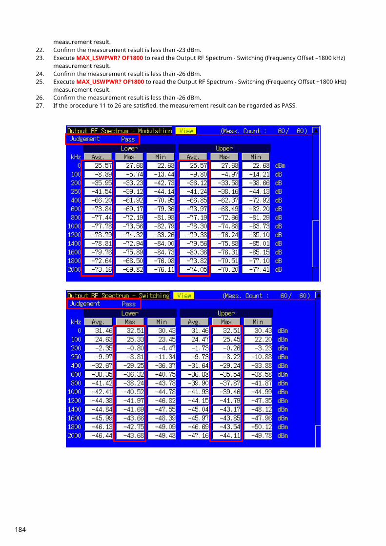
measurement result. 22. Confirm the measurement result is less than -23 dBm. 23. Execute MAX_LSWPWR? OF1800 to read the Output RF Spectrum - Switching (Frequency Offset –1800 kHz)
measurement result. 24. Confirm the measurement result is less than -26 dBm. 25. Execute MAX_USWPWR? OF1800 to read the Output RF Spectrum - Switching (Frequency Offset +1800 kHz)
measurement result. 26. Confirm the measurement result is less than -26 dBm. 27. If the procedure 11 to 26 are satisfied, the measurement result can be regarded as PASS.
184

Table 2.3.7.2-1 3GPP TS51.010-1 Table 13-11:GSM Spectrum due to switching transients
Power level Maximum level for various offsets from carrier frequency
400 kHz 600 kHz 1 200 kHz 1 800 kHz 39 dBm -13 dBm -21 dBm -21 dBm -24 dBm 37 dBm -15 dBm -21 dBm -21 dBm -24 dBm 35 dBm -17 dBm -21 dBm -21 dBm -24 dBm 33 dBm -19 dBm -21 dBm -21 dBm -24 dBm 31 dBm -21 dBm -23 dBm -23 dBm -26 dBm 29 dBm -23 dBm -25 dBm -25 dBm -28 dBm 27 dBm -23 dBm -26 dBm -27 dBm -30 dBm 25 dBm -23 dBm -26 dBm -29 dBm -32 dBm 23 dBm -23 dBm -26 dBm -31 dBm -34 dBm
<= +21 dBm -23 dBm -26 dBm -32 dBm -36 dBm
2.3.8. 14.2.1 Reference sensitivity – TCH/FS
1. Connect using Loopback. 2. Execute LBTYPE FASTSPEECH to set [Loop Back Type] to [C(FAST, Speech)]. 3. Execute BER_MEAS ON to set [Bit Error Rate] measurement to [On]. 4. Execute BER_SAMPLE FAST,10000 to set Number of Sample - [FAST] to [10000]. 5. Execute OLVL -104.0 to set [Output Level] to [–104.0] dBm. 6. Execute SWP to perform BER measurement. 7. Execute BER? FAST to read the BER measurement result.
This procedure does not follow the 3GPP specified procedure.
185
2.3.9. Measurement Time Reduction using Batch Process The above Tx/Rx test items can be measured under the same measurement conditions, so measurement time can be cut by measuring all items simultaneously.
1. Connect using Loopback. 2. Execute LBTYPE FASTSPEECH to set [Loop Back Type] to [C(FAST, Speech)]. 3. Execute PWR_TEMPSTD to set Template Judgment Lines to the standard matching Channel and MS Power
Level. 4. Execute ALLMEASITEMS ON,OFF,60,ON,OFF,ON,OFF,ON,OFF,60,ON,OFF,60,ON,OFF,60,ON,OFF to set all
items to [On] and to set [Average Count] to [60] times. 5. Execute BER_SAMPLE FAST,10000 to set Number of Sample - [FAST] to [10000]. 6. Execute OLVL -104.0 to set [Output Level] to [–104.0] dBm. 7. Execute SWP to perform measurement. 8. Execute AVG_TXPWR? to read the measurement results.
2.4. Connection with GPRS Attach (location registration) must be executed with GPRS to test with GPRS. When Attach is completed, the Call Processing state changes to Attached.
2.4.1. Attach procedures
1. Execute PRESET to preset parameter. 2. Execute OPEMODE GPRS to set [Operating Mode] to [GPRS]. 3. Turn on the UE. 4. Execute CALLSTAT? and wait until it becomes 13 (= Attached).
(*) Some UEs do not execute Attach at power-on. In this case, check the UE settings.
2.4.2. Connection Type Select one of following methods to execute Tx/Rx measurement with GPRS. TX measurement: Test Mode A or Test Mode B (3GPP recommends TestModeA.) RX measurement: BLER
186

2.4.3. Multi-slot setting To use Multi Slot, set the Multi-slot Configuration parameter. The slot number is limited by each Multi-slot Class. See Table 2.4-1 for the slot number. This instrument supports Class 1 to 12 and 30 to 33. The Multi-slot Class can be checked at the Report screen after the Attach process (2.4.1).
Table 2.4-1
Multi-slot Class
Maximum number of slots
Rx Tx Sum
1 1 1 2
2 2 1 3
3 2 2 3
4 3 1 4
5 2 2 4
6 3 2 4
7 3 3 4
8 4 1 5
9 3 2 5
10 4 2 5
11 4 3 5
12 4 4 5
30 5 1 6
31 5 2 6
32 5 3 6
33 5 4 6
34 5 5 6 Rx: Maximum slot number that UE can receive in 1 frame (This instrument uses DL display.) Tx: Maximum slot number that UE can send in 1 frame (This instrument uses UL display.) SUM: Maximum slot number that can be transmitted/received simultaneously by combining Rx and Tx slot number.
187
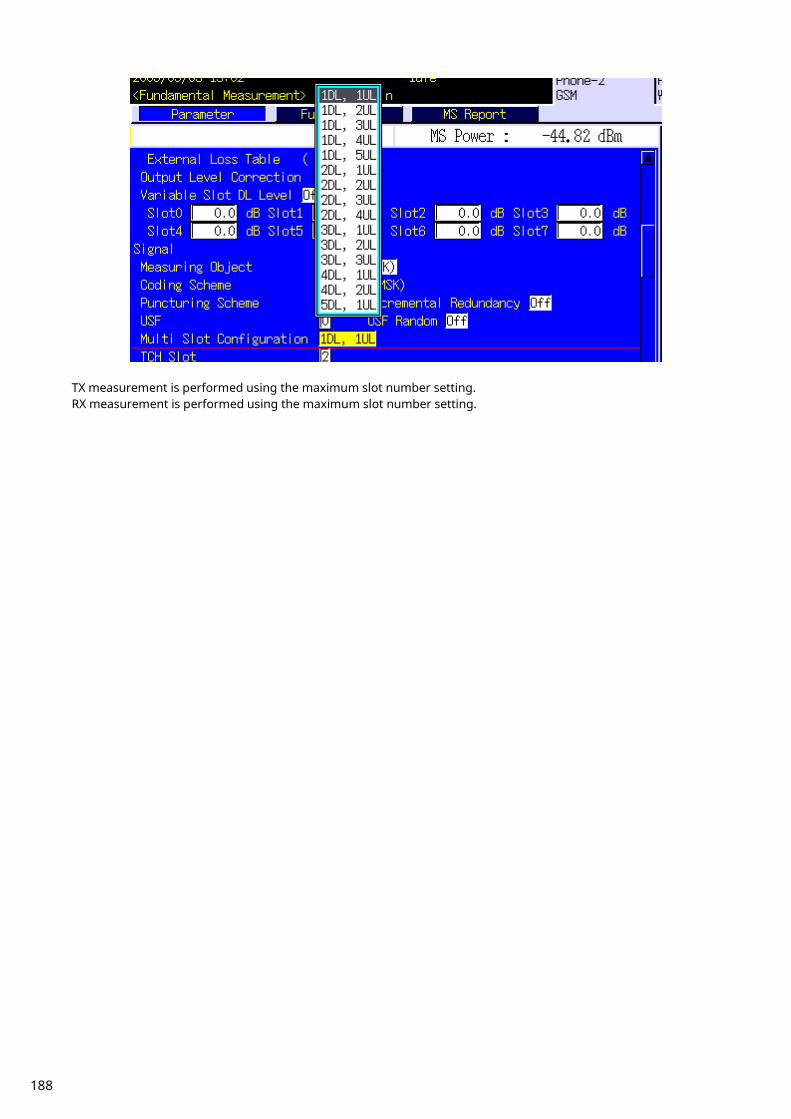
TX measurement is performed using the maximum slot number setting. RX measurement is performed using the maximum slot number setting.
188
2.4.4. Change of TCH Channel, MS Power Level and CS (Coding Scheme) at Handover Usually, Tx/Rx measurement is performed at three frequency points (L, M, H). Tx measurement is performed by changing the Slot power level, and Rx measurement is performed by changing the coding scheme (CS). In this case, measurement can be performed quickly without reconnection by switching the TCH Channel, MS Power Level, and CS at handover with a higher output level. When a GPIB command is sent during handover, it waits until handover ends. [TX Measurement]
1. Execute CHMSPWR 1,5,5 to change [TCH Channel] to [1] CH, MS Power Level - [1st Slot] to [5], MS Power Level - [2nd Slot] to [5].
2. Perform TX measurement. 3. Execute CHMSPWR 1,19,5 to change [TCH Channel] to [1] CH, MS Power Level - [1st Slot] to [19], MS Power
Level - [2nd Slot] to [5]. 4. Perform TX measurement. 5. Execute CHMSPWR 1,5,19 to change [TCH Channel] to [1] CH, MS Power Level - [1st Slot] to [5], MS Power
Level - [2nd Slot] to [19]. 6. Perform TX measurement. 7. Execute CHMSPWR 63,5,5 to change [TCH Channel] to [63] CH, MS Power Level - [1st Slot] to [5], MS Power
Level - [2nd Slot] to [5]. 8. Perform TX measurement. 9. Execute CHMSPWR 63,19,5 to change [TCH Channel] to [63] CH, MS Power Level - [1st Slot] to [19], MS Power
Level - [2nd Slot] o [5]. 10. Perform TX measurement. 11. Execute CHMSPWR 63,5,19 to change [TCH Channel] to [63] CH, MS Power Level - [1st Slot ] to [5], MS Power
Level - [2nd Slot] to [19]. 12. Perform TX measurement. 13. Execute CHMSPWR 127,5,5 to change [TCH Channel] to [127] CH, MS Power Level - [1st Slot] to [5], MS Power
Level - [2nd Slot] to [5]. 14. Perform TX measurement. 15. Execute CHMSPWR 127,19,5 to change [TCH Channel] to [127] CH, MS Power Level - [1st Slot] to [19], MS
Power Level - [2nd Slot] to [5]. 16. Perform TX measurement. 17. Execute CHMSPWR 127,5,19 to change [TCH Channel] to [127] CH, MS Power Level - [1st Slot] to [5], MS
Power Level - [2nd Slot] to [19]. 18. Perform TX measurement. [RX Measurement]
1. Execute CHMSPWR 1,5 to change [TCH Channel] to [1] CH, [MS Power Level] to [5]. 2. Execute CS CS3 to change [Coding Scheme] to [CS-3]. 3. Perform RX measurement. 4. Execute CS CS4 to change [Coding Scheme] to [CS-4]. 5. Perform RX measurement. 6. Execute CHMSPWR 63,5 to change [TCH Channel] to [63] CH, [MS Power Level] to [5]. 7. Execute CS CS3 to change [Coding Scheme] to [CS-3]. 8. Perform RX measurement. 9. Execute CS CS4 to change [Coding Scheme] to [CS-4].
10. Perform RX measurement. 11. Execute CHMSPWR 127,5 to change [TCH Channel] to [127] CH, [MS Power Level] to [5]. 12. Execute CS CS3 to change [Coding Scheme] to [CS-3]. 13. Perform RX measurement. 14. Execute CS CS4 to change [Coding Scheme] to [CS-4]. 15. Perform RX measurement.
189
2.5. TX Measurement (GPRS) Measurement of Tx 2 slot is performed by connecting using Test Mode A. The connection procedures are shown below.
2.5.1. Connection with Test Mode A The following procedures are performed after Attach (section 2.4.1).
1. Execute CONNTYPE MODEA to set [Connection Type] to [Test Mode A]. 2. Execute MLTSLTCFG 2DL2UL to set [Multi Slot Configuration] to [2DL, 2UL], meaning 2Slot for Downlink and
Uplink. 3. Execute CALLSA to connect with Test Mode A. 4. Execute CALLSTAT? and wait until the response returns 14 (= Transfer).
2.5.2. Disconnection from Test Mode A At connection of Test Mode A and Test Mode B, communication is disconnected automatically from the UE side when the data transmission set at [Number of PDUs for Test Mode] is completed. Therefore, the connection state must be confirmed before disconnection.
1. Execute CALLSTAT? and confirm it is 14 (= Transfer). If it is 13 (= Attached), it is already disconnected. 2. Execute CALLSO to disconnect Test Mode. 3. Execute CALLSTAT? and wait until the response returns 13 (= Attached).
190
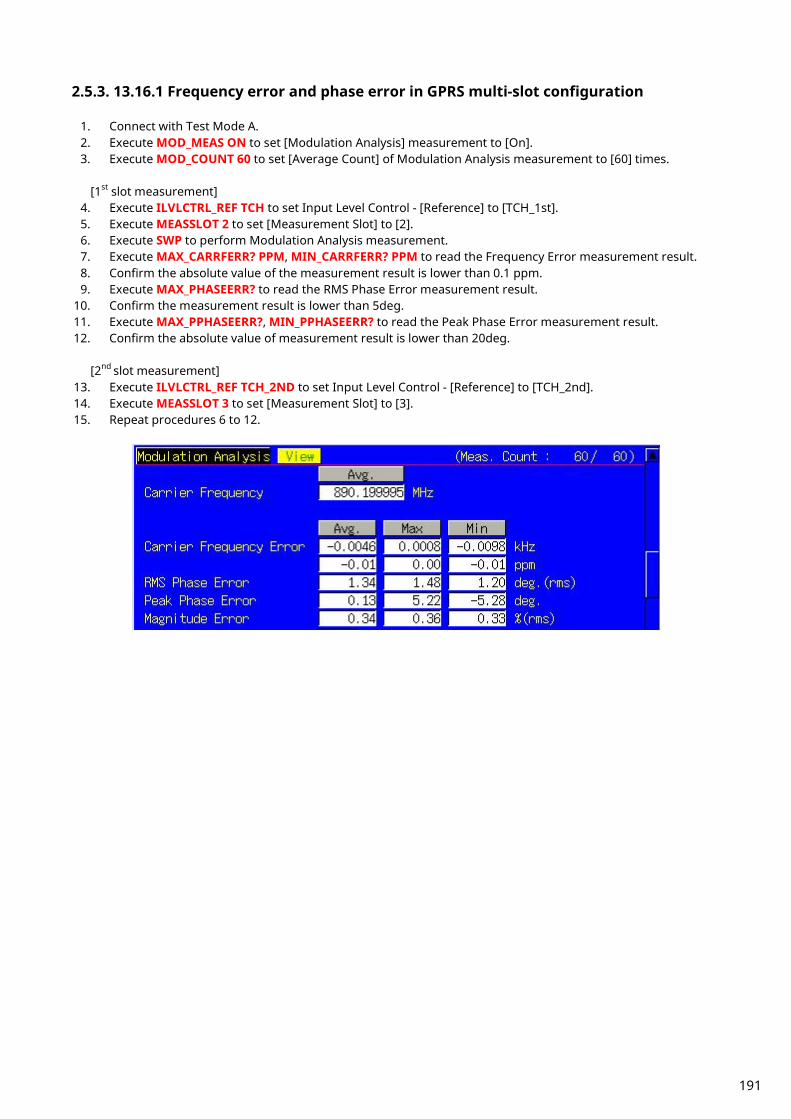
2.5.3. 13.16.1 Frequency error and phase error in GPRS multi-slot configuration
1. Connect with Test Mode A. 2. Execute MOD_MEAS ON to set [Modulation Analysis] measurement to [On]. 3. Execute MOD_COUNT 60 to set [Average Count] of Modulation Analysis measurement to [60] times.
[1st slot measurement]
4. Execute ILVLCTRL_REF TCH to set Input Level Control - [Reference] to [TCH_1st]. 5. Execute MEASSLOT 2 to set [Measurement Slot] to [2]. 6. Execute SWP to perform Modulation Analysis measurement. 7. Execute MAX_CARRFERR? PPM, MIN_CARRFERR? PPM to read the Frequency Error measurement result. 8. Confirm the absolute value of the measurement result is lower than 0.1 ppm. 9. Execute MAX_PHASEERR? to read the RMS Phase Error measurement result.
10. Confirm the measurement result is lower than 5deg. 11. Execute MAX_PPHASEERR?, MIN_PPHASEERR? to read the Peak Phase Error measurement result. 12. Confirm the absolute value of measurement result is lower than 20deg.
[2nd slot measurement]
13. Execute ILVLCTRL_REF TCH_2ND to set Input Level Control - [Reference] to [TCH_2nd]. 14. Execute MEASSLOT 3 to set [Measurement Slot] to [3]. 15. Repeat procedures 6 to 12.
191

2.5.4. 13.16.2 Transmitter Output Power in GPRS Multi-slot Configuration
1. Connect using Test Mode A. 2. Execute PWR_MEAS ON to set [Power Measurement] to [On]. 3. Execute TEMP_MEAS ON to set [Template] measurement to [On]. 4. Execute PWR_COUNT 60 to set [Average Count] of Power Measurement to [60] times.
[1st slot measurement]
5. Execute ILVLCTRL_REF TCH to set Input Level Control - [Reference] to [TCH_1st]. 6. Execute MEASSLOT 2 to set [Measurement Slot] to [2]. 7. Execute PWR_TEMPSTD to set Template Judgment Lines to the standard matching Channel and MS Power
Level. 8. Execute SWP to perform Power measurement. 9. Execute AVG_TXPWR? to read the Power measurement result.
10. Execute AVG_PWRTEMP? to read the Template measurement result. 11. Confirm the measurement result is PASS.
[2nd slot measurement]
12. Execute ILVLCTRL_REF TCH_2ND to set Input Level Control - [Reference] to [TCH_2nd]. 13. Execute MEASSLOT 3 to set [Measurement Slot] to [3]. 14. Repeat procedures 7 to 11.
192

2.5.5. 13.16.3 Output RF Spectrum in GPRS Multi-slot Configuration
1. Connect using Test Mode A. 2. Execute ORFSMD_MEAS ON to set [Output RF Spectrum - Modulation] measurement to [On]. 3. Execute ORFSSW_MEAS ON to set [Output RF Spectrum - Switching] measurement to [On]. 4. Execute ORFSMD_COUNT 60 to set [Average Count] of Output RF Spectrum - Modulation measurement to
[60] times. 5. Execute ORFSSW_COUNT 60 to set [Average Count] of Output RF Spectrum - Switching measurement to [60]
times. [1st slot measurement]
6. Execute ILVLCTRL_REF TCH to set Input Level Control - [Reference] to [TCH_1st]. 7. Execute MEASSLOT 2 to set [Measurement Slot] to [2]. 8. Execute SWP to perform ORFS measurements. 9. Execute ORFSMD_JUDGE? to read the Output RF Spectrum - Modulation measurement result.
10. Confirm the measurement result is PASS. *The PASS/FAIL criterion for ORFS Switching measurement is different between the MT8820C/MT8821C and 3GPP TS 51.010-1. The MT8820C/MT8821C evaluates from all points of 0 to 2000 kHz. The 3GPP TS 51.010-1 evaluates from points 400, 600, 1200, and 1800 kHz. When using the MT8820C/MT8821C judgment result, go to section 2.5.5.1 ORFS Switching measurement in GPRS multi-slot configuration: When using MT8820C/MT8821C judgment result. When using the 3GPP measurement procedure, go to section 2.5.5.2 ORFS Switching measurement in GPRS multi-slot configuration: When using 3GPP TS 51.010-1. 2.5.5.1 ORFS Switching measurement in GPRS multislot configuration: : When using MT8820C/MT8821C judgment result 11. Execute ORFSSW_JUDGE? to read the Output RF Spectrum - Switching measurement result. 12. Confirm the measurement result is PASS.
[2nd slot measurement]
13. Execute ILVLCTRL_REF TCH_2ND to set Input Level Control - [Reference] to [TCH_2nd]. 14. Execute MEASSLOT 3 to set [Measurement Slot] to [3]. 15. Repeat procedures 8 to 12. 2.5.5.2 ORFS Switching measurement in GPRS multislot configuration: When using 3GPP TS 51.010-1 measurement procedure The 3GPP TS51.010-1 measurement procedure is as follows. Evaluate from the measurement result for 400, 600, 1200, and 1800 kHz (Table 2.5.5.2-1). The reference value differs with the Power level. This section describes an example when Power level = 31 dBm. *The reference value is different when the operating band is DCS1800 or PCS1900. Refer to TS51.010-1 13.16.3 Output RF spectrum in GPRS multi-slot configuration. 11. Execute MAX_LSWPWR? OF400 to read the Output RF Spectrum - Switching (Frequency Offset –400 kHz)
measurement result. 12. Confirm the measurement result is less than -21dBm. 13. Execute MAX_USWPWR? OF400 to read the Output RF Spectrum - Switching (Frequency Offset +400 kHz)
measurement result. 14. Confirm the measurement result is less than -21dBm. 15. Execute MAX_LSWPWR? OF600 to read the Output RF Spectrum - Switching (Frequency Offset –600 kHz)
measurement result. 16. Confirm the measurement result is less than -23 dBm. 17. Execute MAX_USWPWR? OF600 to read the Output RF Spectrum - Switching (Frequency Offset +600 kHz)
measurement result.
193

18. Confirm the measurement result is less than -23 dBm. 19. Execute MAX_LSWPWR? OF1200 to read the Output RF Spectrum - Switching (Frequency Offset –1200 kHz)
measurement result. 20. Confirm the measurement result is less than -23 dBm. 21. Execute MAX_USWPWR? OF1200 to read the Output RF Spectrum - Switching (Frequency Offset +1200 kHz)
measurement result. 22. Confirm the measurement result is less than -23 dBm. 23. Execute MAX_LSWPWR? OF1800 to read the Output RF Spectrum - Switching (Frequency Offset –1800 kHz)
measurement result. 24. Confirm the measurement result is less than -26 dBm. 25. Execute MAX_USWPWR? OF1800 to read the Output RF Spectrum - Switching (Frequency Offset +1800 kHz)
measurement result. 26. Confirm the measurement result is less than -26 dBm. 27. If the procedure 11 to 26 are satisfied, the measurement result can be regarded as PASS.
[2nd slot measurement] 28. Execute ILVLCTRL_REF TCH_2ND to set Input Level Control - [Reference] to [TCH_2nd]. 29. Execute MEASSLOT 3 to set [Measurement Slot] to [3]. 30. Repeat procedures 8 to 27.
Table 2.5.5.2-1 3GPP TS51.010-1 Table 13.16.3-6:GSM Spectrum due to switching transients
Power level Maximum level for various offsets from carrier frequency 400 kHz 600 kHz 1200 kHz 1 800 kHz 39 dBm -13 dBm -21 dBm -21 dBm -24 dBm 37 dBm -15 dBm -21 dBm -21 dBm -24 dBm 35 dBm -17 dBm -21 dBm -21 dBm -24 dBm 33 dBm -19 dBm -21 dBm -21 dBm -24 dBm 31 dBm -21 dBm -23 dBm -23 dBm -26 dBm 29 dBm -23 dBm -25 dBm -25 dBm -28 dBm 27 dBm -23 dBm -26 dBm -27 dBm -30 dBm 25 dBm -23 dBm -26 dBm -29 dBm -32 dBm 23 dBm -23 dBm -26 dBm -31 dBm -34 dBm
<= +21 dBm -23 dBm -26 dBm -32 dBm -36 dBm
194
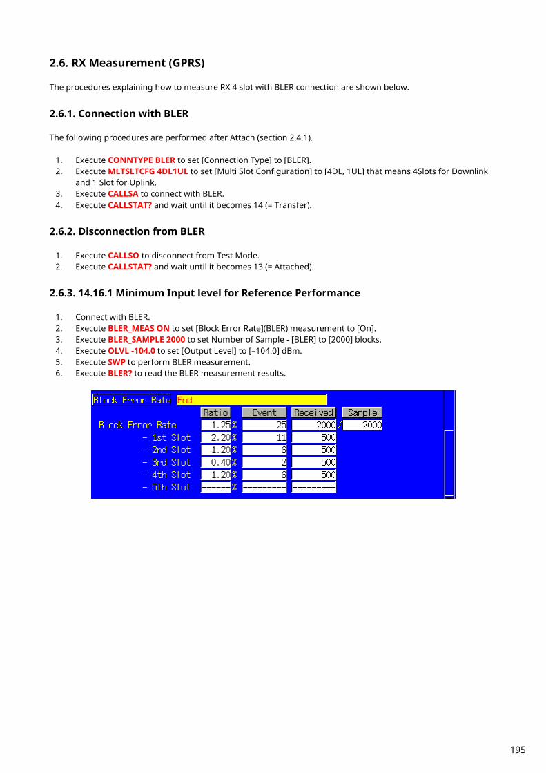
2.6. RX Measurement (GPRS) The procedures explaining how to measure RX 4 slot with BLER connection are shown below.
2.6.1. Connection with BLER The following procedures are performed after Attach (section 2.4.1).
1. Execute CONNTYPE BLER to set [Connection Type] to [BLER]. 2. Execute MLTSLTCFG 4DL1UL to set [Multi Slot Configuration] to [4DL, 1UL] that means 4Slots for Downlink
and 1 Slot for Uplink. 3. Execute CALLSA to connect with BLER. 4. Execute CALLSTAT? and wait until it becomes 14 (= Transfer).
2.6.2. Disconnection from BLER
1. Execute CALLSO to disconnect from Test Mode. 2. Execute CALLSTAT? and wait until it becomes 13 (= Attached).
2.6.3. 14.16.1 Minimum Input level for Reference Performance
1. Connect with BLER. 2. Execute BLER_MEAS ON to set [Block Error Rate](BLER) measurement to [On]. 3. Execute BLER_SAMPLE 2000 to set Number of Sample - [BLER] to [2000] blocks. 4. Execute OLVL -104.0 to set [Output Level] to [–104.0] dBm. 5. Execute SWP to perform BLER measurement. 6. Execute BLER? to read the BLER measurement results.
195

2.7. Connection with EGPRS Measurement with EGPRS is executed after Attach (location registration).
2.7.1. Attach Procedure
1. Execute PRESET to preset the parameters. 2. Execute OPEMODE EGPRS to set [Operating Mode] to [EGPRS]. 3. Turn on the UE power. 4. Execute CALLSTAT? and wait until it becomes 13 (= Attached).
(*) Some UE do not execute Attach at power-on. In this case, check the UE setting.
2.7.2. Connection Type Select one of following methods to execute TX/RX measurement with EGPRS. TX measurement: Test Mode A RX measurement: BLER, SRB Loopback
2.7.3. Multi-slot Setting See item 2.4.3.
2.7.4. Change of TCH Channel, MS Power Level, CS (Coding Scheme) by Handover See item 2.4.4.
196
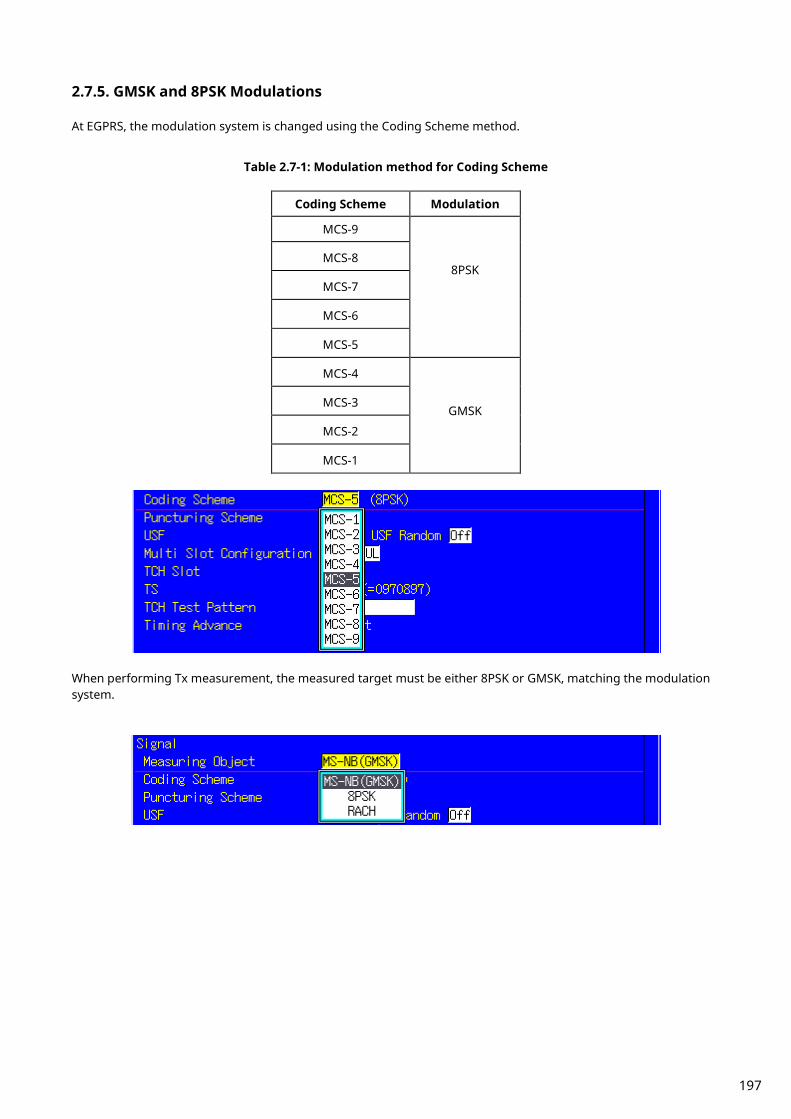
2.7.5. GMSK and 8PSK Modulations At EGPRS, the modulation system is changed using the Coding Scheme method.
Table 2.7-1: Modulation method for Coding Scheme
Coding Scheme Modulation
MCS-9
8PSK MCS-8
MCS-7
MCS-6
MCS-5
MCS-4
GMSK MCS-3
MCS-2
MCS-1
When performing Tx measurement, the measured target must be either 8PSK or GMSK, matching the modulation system.
197
2.8. TX Measurement (EGPRS) The procedures below explain how to measure MCS-5 and TX 2 slot by connecting using Test Mode A and using Coding Scheme (CS).
2.8.1. Connection with Test Mode A Perform the following procedures after Attach (section 2.7.1).
1. Execute CONNTYPE MODEA to set [Connection Type] to [Test Mode A]. 2. Execute MLTSLTCFG 2DL2UL to set [Multi-slot Configuration] to [2DL, 2UL] that means 2Slots for Downlink
and 2 Slot for Uplink. 3. Execute CS MCS5 to set [Coding Scheme] to [MCS-5]. 4. Execute CALLSA to connect using Test Mode A. 5. Execute CALLSTAT? and wait until it becomes 14 (= Transfer).
2.8.2. Disconnection from Test Mode A When connecting using Test Mode A, disconnection is performed automatically from the UE side when sending of (Number of PDUs for Test Mode) is completed. Therefore, check the connection state before disconnecting.
1. Execute CALLSTAT? and confirm it is 14 (= Transfer). If it is 13 (= Attached), it is already disconnected. 2. Execute CALLSO to disconnect Test Mode A. 3. Execute CALLSTAT? and wait until it becomes 13 (= Attached).
198
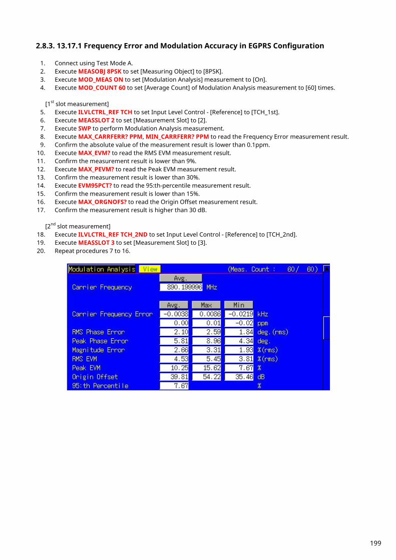
2.8.3. 13.17.1 Frequency Error and Modulation Accuracy in EGPRS Configuration
1. Connect using Test Mode A. 2. Execute MEASOBJ 8PSK to set [Measuring Object] to [8PSK]. 3. Execute MOD_MEAS ON to set [Modulation Analysis] measurement to [On]. 4. Execute MOD_COUNT 60 to set [Average Count] of Modulation Analysis measurement to [60] times.
[1st slot measurement]
5. Execute ILVLCTRL_REF TCH to set Input Level Control - [Reference] to [TCH_1st]. 6. Execute MEASSLOT 2 to set [Measurement Slot] to [2]. 7. Execute SWP to perform Modulation Analysis measurement. 8. Execute MAX_CARRFERR? PPM, MIN_CARRFERR? PPM to read the Frequency Error measurement result. 9. Confirm the absolute value of the measurement result is lower than 0.1ppm.
10. Execute MAX_EVM? to read the RMS EVM measurement result. 11. Confirm the measurement result is lower than 9%. 12. Execute MAX_PEVM? to read the Peak EVM measurement result. 13. Confirm the measurement result is lower than 30%. 14. Execute EVM95PCT? to read the 95:th-percentile measurement result. 15. Confirm the measurement result is lower than 15%. 16. Execute MAX_ORGNOFS? to read the Origin Offset measurement result. 17. Confirm the measurement result is higher than 30 dB.
[2nd slot measurement]
18. Execute ILVLCTRL_REF TCH_2ND to set Input Level Control - [Reference] to [TCH_2nd]. 19. Execute MEASSLOT 3 to set [Measurement Slot] to [3]. 20. Repeat procedures 7 to 16.
199
2.8.4. 13.17.3 EGPRS Transmitter Output Power
1. Connect using Test Mode A. 2. Execute MEASOBJ 8PSK to set [Measuring Object] to [8PSK]. 3. Execute PWR_MEAS ON to set [Power Measurement] to [On]. 4. Execute TEMP_MEAS ON to set [Template] measurement to [On]. 5. Execute PWR_COUNT 60 to set [Average Count] of Power measurement to [60] times.
[1st slot measurement]
6. Execute ILVLCTRL_REF TCH to set Input Level Control - [Reference] to [TCH_1st]. 7. Execute MEASSLOT 2 to set [Measurement Slot] to [2]. 8. Execute PWR_TEMPSTD to set Template Judgment Lines to the standard matching the Channel and MS
Power Level. 9. Execute SWP to perform Power measurement.
10. Execute AVG_TXPWR? to read the Power measurement result. 11. Execute EST8PSKPWR? to read the Estimated 8PSK Power measurement result. 12. Execute AVG_PWRTEMP? to read the Template measurement result. 13. Confirm the measurement result is PASS.
Estimated 8PSK Power measurement calculates the long-term average Power. [2nd slot measurement]
14. Execute ILVLCTRL_REF TCH_2ND to set Input Level Control - [Reference] to [TCH_2nd]. 15. Execute MEASSLOT 3 to set [Measurement Slot] to [3]. 16. Repeat procedures 8 to 13.
2.8.5. 13.17.3 Output RF Spectrum in EGPRS Configuration
1. Connect using Test Mode A. 2. Execute MEASOBJ 8PSK to set [Measuring Object] to [8PSK]. 3. Execute ORFSMD_MEAS ON to set [Output RF Spectrum - Modulation] measurement to [On]. 4. Execute ORFSSW_MEAS ON to set [Output RF Spectrum - Switching] measurement to [On]. 5. Execute ORFSMD_COUNT 60 to set [Average Count] of Output RF Spectrum - Modulation measurement to
[60] times. 6. Execute ORFSSW_COUNT 60 to set [Average Count] of Output RF Spectrum - Switching measurement to [60]
times. [1st slot measurement]
7. Execute ILVLCTRL_REF TCH to set Input Level Control - [Reference] to [TCH_1st]. 8. Execute MEASSLOT 2 to set [Measurement Slot] to [2]. 9. Execute SWP to perform ORFS measurements.
10. Execute ORFSMD_JUDGE? to read the Output RF Spectrum - Modulation measurement result. 11. Confirm the measurement result is PASS. *The PASS/FAIL criterion for ORFS Switching measurement is different between the MT8820C/MT8821C and 3GPP TS 51.010-1. The MT8820C/MT8821C evaluates from all points of 0 to 2000 kHz. The 3GPP TS 51.010-1 evaluates from points 400, 600, 1200, and 1800 kHz. When using the MT8820C/MT8821C judgment result, go to section 2.8.5.1 ORFS Switching measurement in EGPRS configuration: When using MT8820C/MT8821C judgment result. When using the 3GPP measurement procedure, go
to section 2.8.5.2 ORFS Switching measurement in EGPRS configuration: When using 3GPP TS 51.010-1
measurement procedure.
200

2.8.5.1 ORFS Switching measurement in EGPRS configuration: When using a judgment result of MT8820C/MT8821C 12. Execute ORFSSW_JUDGE? to read the Output RF Spectrum - Switching measurement result. 13. Confirm the measurement result is PASS.
[2nd slot measurement]
14. Execute ILVLCTRL_REF TCH_2ND to set Input Level Control - [Reference] to TCH_2nd]. 15. Execute MEASSLOT 3 to set [Measurement Slot] to [3]. 16. Repeat procedures 9 to 13. 2.8.5.2 ORFS Switching measurement in EGPRS configuration: When using 3GPP TS 51.010-1 measurement procedure The 3GPP TS51.010-1 measurement procedure is as follows. Evaluate from the measurement results for 400, 600, 1200, and 1800 kHz (Table 2.8.5.2-1). The reference value differs with Power level. This section describes an example when Power level = 31 dBm. *The reference value is different when the operating band is DCS1800 or PCS1900. Refer to TS51.010-1 13.17.4 Output RF spectrum in EGPRS configuration. 12. Execute MAX_LSWPWR? OF400 to read the Output RF Spectrum - Switching (Frequency Offset –400 kHz)
measurement result. 13. Confirm the measurement result is less than -21dBm. 14. Execute MAX_USWPWR? OF400 to read the Output RF Spectrum - Switching (Frequency Offset +400 kHz)
measurement result. 15. Confirm the measurement result is less than -21dBm. 16. Execute MAX_LSWPWR? OF600 to read the Output RF Spectrum - Switching (Frequency Offset –600 kHz)
measurement result. 17. Confirm the measurement result is less than -23 dBm. 18. Execute MAX_USWPWR? OF600 to read the Output RF Spectrum - Switching (Frequency Offset +600 kHz)
measurement result. 19. Confirm the measurement result is less than -23 dBm. 20. Execute MAX_LSWPWR? OF1200 to read the Output RF Spectrum - Switching (Frequency Offset –1200 kHz)
measurement result. 21. Confirm the measurement result is less than -23 dBm. 22. Execute MAX_USWPWR? OF1200 to read the Output RF Spectrum - Switching (Frequency Offset +1200 kHz)
measurement result. 23. Confirm the measurement result is less than -23 dBm. 24. Execute MAX_LSWPWR? OF1800 to read the Output RF Spectrum - Switching (Frequency Offset –1800 kHz)
measurement result. 25. Confirm the measurement result is less than -26 dBm. 26. Execute MAX_USWPWR? OF1800 to read the Output RF Spectrum - Switching (Frequency Offset +1800 kHz)
measurement result. 27. Confirm the measurement result is less than -26 dBm. 28. If the procedure 12 to 27 are satisfied, the measurement result can be regarded as PASS.
[2nd slot measurement] 29. Execute ILVLCTRL_REF TCH_2ND to set Input Level Control - [Reference] to [TCH_2nd]. 30. Execute MEASSLOT 3 to set [Measurement Slot] to [3]. 31. Repeat procedures 9 to 28.
201
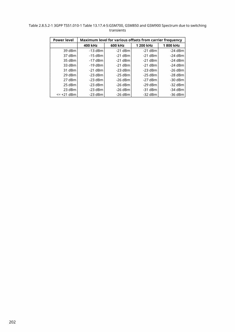
Table 2.8.5.2-1 3GPP TS51.010-1 Table 13.17.4-5:GSM700, GSM850 and GSM900 Spectrum due to switching transients
Power level Maximum level for various offsets from carrier frequency
400 kHz 600 kHz 1 200 kHz 1 800 kHz 39 dBm -13 dBm -21 dBm -21 dBm -24 dBm 37 dBm -15 dBm -21 dBm -21 dBm -24 dBm 35 dBm -17 dBm -21 dBm -21 dBm -24 dBm 33 dBm -19 dBm -21 dBm -21 dBm -24 dBm 31 dBm -21 dBm -23 dBm -23 dBm -26 dBm 29 dBm -23 dBm -25 dBm -25 dBm -28 dBm 27 dBm -23 dBm -26 dBm -27 dBm -30 dBm 25 dBm -23 dBm -26 dBm -29 dBm -32 dBm 23 dBm -23 dBm -26 dBm -31 dBm -34 dBm
<= +21 dBm -23 dBm -26 dBm -32 dBm -36 dBm
202

2.9. RX Measurement (EGPRS) The procedures explaining how to measure RX 4 slot with BLER connection are shown below.
2.9.1. Connection with BLER The following procedures are performed after Attach (section 2.7.1).
1. Execute CONNTYPE BLER to set [Connection Type] to [BLER]. 2. Execute MLTSLTCFG 4DL1UL to set [Multi Slot Configuration] to [4DL, 1UL] that means 4Slots for Downlink
and 1 Slot for Uplink. 3. Execute CALLSA to connect with BLER. 4. Execute CALLSTAT? and wait until the status becomes 14 (= Transfer).
2.9.2. Disconnection from BLER
1. Execute CALLSO to disconnect from Test Mode. 2. Execute CALLSTAT? and wait until the status becomes 13 (= Attached).
2.9.3. 14.18.1 Minimum Input level for Reference Performance
1. Connect using BLER. 2. Execute BLER_MEAS ON to set [Block Error Rate] (BLER) measurement to [On]. 3. Execute BLER_SAMPLE 2000 to set Number of Sample - [BLER] to [2000] blocks. 4. Execute OLVL -104.0 to set [Output Level] to [–104.0] dBm. 5. Execute SWP to perform BLER measurement. 6. Execute BLER? to read the BLER measurement results.
203

2.10. MS Report This function reads the Measurement Report provided regularly (every 480 ms) from the UE. Note: After changing the Downlink Level, two reports are measured using the level before the change.
1. Connect using UE. 2. Execute OLVL -104.0 to set [Output Level] to [–104.0] dBm. 3. Execute CALLRFR to preset Flag. 4. Execute CALLREP? and wait until Flag becomes 1 (first). 5. Execute CALLRFR to preset Flag. 6. Execute CALLREP? and wait until Flag becomes 1 (second). 7. Execute CALLRFR to preset Flag. 8. Execute CALLREP? and wait until Flag becomes 1 (third), and read RX Level and RX Quality.
2.11. Functional Test
2.11.1. Voice Call For GSM, the Call Processing function supports Voice Call tests with each speech channel. This measuring instrument supports the speech channels shown below.
2.11-1: Speech Channel Support Chart
FS 13.0 kbps EFS 12.2 kbps
HS 11.4 kbps
AFS 12.2 kbps
10.2 kbps
7.95 kbps
7.40 kbps
6.70 kbps
5.90 kbps
5.15 kbps
4.75 kbps
AHS 7.95 kbps
7.40 kbps
6.70 kbps
5.90 kbps
5.15 kbps
4.75 kbps
204

An example of how to perform the origination test using the AFS 7.95 kbps voice Codec is shown below. 1. Execute CALLPROC ON to set [Call Processing] to [On]. 2. Execute CODEC AFS to set [Codec] to [AFS]. 3. Execute NBRATE 7.95 to set [Net Bit Rate] to [7.95 kbps]. 4. Call from a UE with any telephone number.
Call Process turns on Origination. The telephone number can be checked on the MS Report screen. 5. Execute CALLSTAT? and wait until it becomes 7 (= Communication).
Call Processing turns on Communication and the instrument and UE can now communicate. 6. Execute TESTPAT ECHO to set [TCH Test Pattern] to [Echo] to perform the voice communication test using
echo-back. 7. Execute CALLSO to disconnect from the equipment, or from the UE after on-hooking.
Call Processing turns on MS Release or NW Release.
Fig. 2.11-1: Connection Sequence
Check each state using the CALLRSLT? command. An example of how to check completion of Registration and Origination is shown below.
1. Execute CALLRSLT? 4 and confirm Registration is 1,0 (= executed, no errors). 2. Execute CALLRSLT? 5 and confirm the Origination status is 1,0 (= executed, no errors).
Each connection sequence can be preset using CALLRFR command
(1) IDLE
(3) Radio Link (4) Registration
(6) Termination (5) Origination
(7) Communication
(9) NW Release (10) MS Release
(11) Radio Disc
(8) Handover
(2) Paging
205

2.11.2. External Packet Data (Option MX882001C-002) For GSM, GPRS packet connection can be tested using the MX882001C-002GSM External Packet Data option and Call Processing function. The connection system supports IP connections. The equipment supports communications between the Server PC and Client PC by supporting the IP protocol over wireless interface and UE.
1. Connection without Gateway
<Items to prepare>
GSM UE with GPRS function Server PC (Application Server) Client PC (Client) Crossover cable for connection between the equipment and Server PC
1. Set 10Base-T [IP Address] to the same segment on the System Config screen. 2. Set 10 Base-T[Subnet Mask] on System Config screen (Example: 255.255.255.0).
Ethernet
IP
TCP/UDP
User Application
Physical Layer
LLC/RLC/MAC
IP
TCP/UDP
Ethernet
IP
Physical Layer
LLC/RLC/MAC
IP
User Application
SNDCP SNDCP
321
654
987
#0*
PC(Client) IP Address: 192.168.20.11
Application Server IP Address: 192.168.20.10
MT8820A IP Address: 192.168.20.2
Ethernet(COM)
UE
Airlink
MT8820B
206
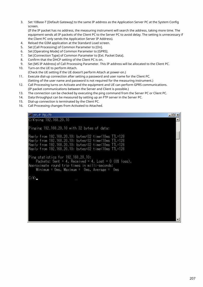
3. Set 10Base-T [Default Gateway] to the same IP address as the Application Server PC at the System Config screen. (If the IP packet has no address, the measuring instrument will search the address, taking more time. The equipment sends all IP packets of the Client PC to the Server PC to avoid delay. The setting is unnecessary if the Client PC only sends the Application Server IP Address).
4. Reload the GSM application at the Standard Load screen. 5. Set [Call Processing] of Common Parameter to [On]. 6. Set [Operating Mode] of Common Parameter to [GPRS]. 7. Set [Connection Type] of Common Parameter to [Ext. Packet Data]. 8. Confirm that the DHCP setting of the Client PC is on. 9. Set [MS IP Address] of Call Processing Parameter. This IP address will be allocated to the Client PC.
10. Turn-on the UE to perform Attach. (Check the UE setting if the UE doesn’t perform Attach at power-on.)
11. Execute dial-up connection after setting a password and user name for the Client PC. (Setting of the user name and password is not required for the measuring instrument.)
12. Call Processing turns on Activate and the equipment and UE can perform GPRS communications. (IP packet communications between the Server and Client is possible.)
13. The connection can be checked by executing the ping command from the Server PC or Client PC. 14. Data throughput can be measured by setting up an FTP server in the Server PC. 15. Dial-up connection is terminated by the Client PC. 16. Call Processing changes from Activated to Attached.
207

2. Connection with Gateway Packet communications between different segments can be verified by connecting a gateway between the equipment and Server PC.
<Items to prepare>
GSM UE with GPRS function Server PC (Application Server) Client PC (Client) Gateway Straight-through cable for connection between equipment and Gateway and between Server PC and Gateway.
1. Set 10Base-T [IP Address] (main frame IP address) to the same segment as Gateway at the System Config
screen. 2. Set 10Base-T [Default Gateway] and [Subnet Mask] at the System Config screen. At this time, the Default
Gateway IP address is set to the same IP address on the LAN side of Router. (For example, if the Default Gateway address is 192.168.20.1, set the LAN IP address to 192.168.20.1).
3. Reload the GSM application at the Standard Load screen. 4. Set [Call Processing] of Common Parameter to [On] 5. Set [Operating Mode] of Common Parameter to [GPRS]. 6. Set [Connection Type] of Common Parameter to [Ext. Packet Data]. 7. Confirm that the Client PC DHCP setting is on. 8. Set [MS IP Address] of Call Processing. This address is allocated to the Client PC at connection. 9. Turn-on the UE to perform Attach.
(Check the UE setting if the UE does not perform Attach at power-on.). 10. Execute dial-up connection after setting a password and user name for the Client PC .
(Setting of the user name and password is not required for the measuring instrument.) 11. Call Processing turns on Activate and the equipment and UE can perform GPRS communications.
(IP packet communications between Server and Client is possible.) 12. The connection can be checked by executing the ping command from the Server or Client PC. 13. Data throughput can be measured by setting up an FTP server in the Server PC. 14. The dial-up connection is terminated at the Client PC. 15. Call Processing changes from Activated to Attached.
321
654
987
#0*
PC(Client) IP Address: 192.168.20.11
Application Server IP Address: 172.16.10.12
Gateway Address: 172.16.10.1
Ethernet(COM)
UE
Airlink
Default Gateway
IP Address: 192.168.20.1
Router
Ethernet
LAN
WAN
MT8820A IP Address: 192.168.20.2
MT8820B
208

2.12. Calibration Measurement Function Refer to the Application Note for UE Calibration about the Calibration Measurement Function.
2.12.1. Adjustment of Orthogonal Modulator by TXIQ Measurement
When adjusting the orthogonal modulator of a GSM UE, the carrier frequency and ±67.708 kHz (symbol rate/4) offset power are measured by outputting a rotating pattern from the UE. The TXIQ function measures the power of frequency points to adjust the orthogonal modulator. Measurement is performed with RBW = 30 kHz. Although TXIQ measurement is performed as a part of modulation analysis by the equipment, the measurement results are not displayed on-screen and can only be acquired by remote command. [Measurement parameter] TXIQ measurement is executed after setting the parameters shown in Table 2.8.2-1. TXIQ measurement is performed as part of modulation analysis. Therefore, ON/OFF setting and average number of measurements follow the modulation analysis parameters.
Table 2.8.2-1: TXIQ Measurement Parameter Setting
No Parameter Setting 1 Call Processing OFF
2 Measuring Object Continuous
3 Modulation Analysis ON
4 Average Count of Modulation
Analysis
Also Average Count of TXIQ measurement
[Remote command] TXIQ measurement is executed simultaneously by setting the parameters shown in Table 2.8.2-1 and performing Fundamental measurement. However, the measurement result is not displayed on-screen and must be acquired by remote command. Commands for reading the TXIQ measurement result are shown in Table 2.8.2-2.
Table 2.8.2-2: Query commands of TXIQ measurement result No Command Function
1 AVG_TXIQ? Queries average value of TXIQ measurement result
2 MAX_TXIQ? Queries maximum value of TXIQ measurement result
3 MIN_TXIQ? Queries minimum value of TXIQ measurement result
The responses to read commands are shown below.
p1, p2, p3, p4, p5, p6, p7, p8, p9
frequency offset Each frequency offset power is mentioned from p1 to p9 in dBm units. Offset frequencies are –270.833 kHz, –203.125 kHz, –135.417 kHz, –67.708 kHz, 0 kHz (carrier frequency), +67.708 kHz, +135.417 kHz, +203.125 kHz, and +270.833 kHz.
209

[Example of remote control] Performing TXIQ measurement with Average Count 10 and read maximum value. send( “CALLPROC OFF” ); /* Call Processing OFF */ send( “MEASOBJ CONT” ); /* Set Measuring Object to Continuous */ send( “MOD_MEAS ON” ); /* Turn on modulation analysis */ send( “MOD_COUNT 10” ); /* Set Average Count of modulation analysis to 10 */ -- Start UE Signal Output -- send( “SWP” ); /* Start Measurement */ send( “MSTAT?” ); /* Measurement Status Reading Command */ read( status ); /* Measurement Status Reading Command */ send( “MAX_TXIQ?” ); /* TXIQ Measurement Result Reading Command */ read( result ); /* TXIQ Measurement Result Reading Command */
210
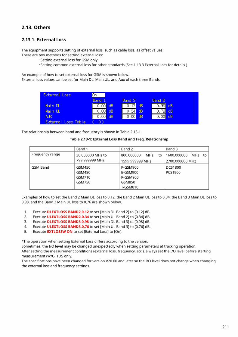
2.13. Others
2.13.1. External Loss The equipment supports setting of external loss, such as cable loss, as offset values. There are two methods for setting external loss:
・Setting external loss for GSM only ・Setting common external loss for other standards (See 1.13.3 External Loss for details.)
An example of how to set external loss for GSM is shown below. External loss values can be set for Main DL, Main UL, and Aux of each three Bands.
The relationship between band and frequency is shown in Table 2.13-1.
Table 2.13-1: External Loss Band and Freq. Relationship
Band 1 Band 2 Band 3 Frequency range 30.000000 MHz to
799.999999 MHz 800.000000 MHz to
1599.999999 MHz
1600.000000 MHz to
2700.000000 MHz
GSM Band GSM450 GSM480 GSM710 GSM750
P-GSM900 E-GSM900 R-GSM900 GSM850 T-GSM810
DCS1800 PCS1900
Examples of how to set the Band 2 Main DL loss to 0.12, the Band 2 Main UL loss to 0.34, the Band 3 Main DL loss to 0.98, and the Band 3 Main UL loss to 0.76 are shown below.
1. Execute DLEXTLOSS BAND2,0.12 to set [Main DL Band 2] to [0.12] dB. 2. Execute ULEXTLOSS BAND2,0.34 to set [Main UL Band 2] to [0.34] dB. 3. Execute DLEXTLOSS BAND3,0.98 to set [Main DL Band 3] to [0.98] dB. 4. Execute ULEXTLOSS BAND3,0.76 to set [Main UL Band 3] to [0.76] dB. 5. Execute EXTLOSSW ON to set [External Loss] to [On].
*The operation when setting External Loss differs according to the version. Sometimes, the I/O level may be changed unexpectedly when setting parameters at tracking operation. After setting the measurement conditions (external loss, frequency, etc.), always set the I/O level before starting measurement (W/G, TDS only) The specifications have been changed for version V20.00 and later so the I/O level does not change when changing the external loss and frequency settings.
211

2.13.2. Power Control (SACCH Channel) When using SACCH Channels to change PCL (Power Control Level), the signal level from the UE changes 2 dB every 60 ms (13TDMA Frame).
Fig. 2.13-1: Power Control using SACCH Channel (changing from PCL 5 to 8)
The procedures explaining how to measure each PCL signal level using this operation are shown below.
1. Connect using UE. (Refer to 2.3.1 to see the connection with GSM.) 2. Execute ALLMEASITEMS ON,OFF,1,OFF,OFF,OFF,OFF,OFF,OFF,1,OFF,OFF,1,OFF,OFF,1,OFF,OFF, to set only
[Power Measurement ] to [On] and to set [Average Count] to [1] time. 3. Execute MEASMODE FAST to set [Measurement Mode] to [FAST] (no graphical display, numeric data only). 4. Execute MSPWR 5 to set [MS Power Level](PCL) to [5]. 5. Execute ILVLCTRL MANUAL to set [Input Level Control] to [Manual] in order to fix INPUT LEVEL to the setting
at PCL 5. 6. Execute MSPWRCTRL SACCH to set the channel to notify change of Power Control Level to SACCH.
(This can be changed only by GPIB command. It cannot be changed on-screen.) 7. Execute MSPWR 15 to change [MS Power Level](PCL) to [15]. 8. Execute SWP;TXPWR? and repeat the measurement until PCL changes.
(If PCL is changed from 5 to 15, at least 1.6 s should be allowed, because the time to change power will be 600 ms and there is also delay between the UE and PC (960 ms max.). Therefore, repeat measurement.)
9. Execute MSPWRCTRL FACCH to set the channel to notify the change of Power Control Level to FACCH. Detect each PCL Power Level from the result of procedure 8. [Example]
MSPWR 15 0 Change [MS Power Level](PCL) from [5] to [15]. SWP;TXPWR? 33.12 Repeat measurement execution (SWP) and read
measurement result. SWP;TXPWR? 33.12 PCL=5 SWP;TXPWR? 33.12 PCL=5 SWP;TXPWR? 33.12 PCL=5 SWP;TXPWR? 33.13 PCL=5 SWP;TXPWR? 33.13 PCL=5 SWP;TXPWR? 33.12 PCL=5 SWP;TXPWR? 33.12 PCL=5 SWP;TXPWR? 33.12 PCL=5 SWP;TXPWR? 33.12 PCL=5 SWP;TXPWR? 33.12 PCL=5 SWP;TXPWR? 30.73 PCL=6 SWP;TXPWR? 29.20 PCL=7
212

SWP;TXPWR? 27.05 PCL=8 SWP;TXPWR? 24.90 PCL=9 SWP;TXPWR? 22.90 PCL=10 SWP;TXPWR? 20.81 PCL=11 SWP;TXPWR? 18.68 PCL=12 SWP;TXPWR? 16.75 PCL=13 SWP;TXPWR? 14.71 PCL=14 SWP;TXPWR? 12.81 PCL=15 SWP;TXPWR? 12.80 PCL=15 SWP;TXPWR? 12.80 PCL=15 SWP;TXPWR? 12.80 PCL=15 SWP;TXPWR? 12.79 PCL=15 SWP;TXPWR? 12.80 PCL=15
Because the SWP; TXPWR? speed depends on the performance of the PC controller, sometimes the PCL timing changes and the measurement result is captured more than twice. In this case, either adjust the actual speed or estimate from the measurement result.
213

2.13.3. MS-TXPWR-MAX-CCH At measurement of 3GPP TS51.010, when MS-TXPWR-MAX-CCH is not specified, the setting of MS-TXPWR-MAX-CCH is set to the maximum Tx power. MS-TXPWR-MAX-CCH is used as Cell Selection Parameter to evaluate whether the UE holds the connection when the BS power is low. Therefore when the setting is high, the connection is easier to disconnect at BER measurement at Reference Sensitivity level.
Table 2.13-3: Maximum Output Power and Power Class Relationship at GMSK Modulation
Power GSM 400 & GSM 900 & GSM 850 & GSM 700
DCS 1 800 PCS 1 900
class Nominal maximum
output power
Nominal maximum
output
Nominal maximum
output power power
1 - - - - - - 1 W (30 dBm) 1 W (30 dBm)
2 8 W (39 dBm) 0, 25 W (24 dBm) 0, 25 W (24 dBm)
3 5 W (37 dBm) 4 W (36 dBm) 2 W (33 dBm)
4 2 W (33 dBm)
5 0, 8 W (29 dBm)
Table 2.13-4: Maximum Output Power and Power Class Relationship at 8PSK Modulation
Power GSM 400 and GSM 900 & GSM 850 & GSM 700
DCS 1 800 PCS 1 900
class Nominal maximum
output
Nominal maximum
output
Nominal maximum
output power power power
E1 33 dBm 30 dBm 30 dBm
E2 27 dBm 26 dBm 26 dBm
E3 23 dBm 22 dBm 22 dBm When measuring using a GSM UE of Power Class 4 (33 dBm max. Tx power), set ms_TXPWR_MAX_CCH to 5. The ms_TXPWR_MAX_CCH setting is the same Power Control Level as the MS Power Level (section 2.13-5). An example of how to set ms_TXPWR_MAX_CCH to 5 is shown below. 1. Execute MSPWR_CCH 5 to set [MS_TXPWR_MAX_CCH] to [5].
214

Table 2.13-5: PCL Setting and Output Power Relationship
GSM 400, GSM 900, GSM 850 and GSM 700 Power control level Nominal output power (dBm)
0 to 2 39
3 37
4 35
5 33
6 31
7 29
8 27
9 25
10 23
11 21
12 19
13 17
14 15
15 13
16 11
17 9
18 7
19 to 31 5
DCS 1 800 Power control level Nominal output power (dBm)
29 36
30 34
31 32
0 30
1 28
2 26
3 24
4 22
5 20
6 18
7 16
8 14
9 12
10 10
11 8
12 6
13 4
14 2
15-28 0
215
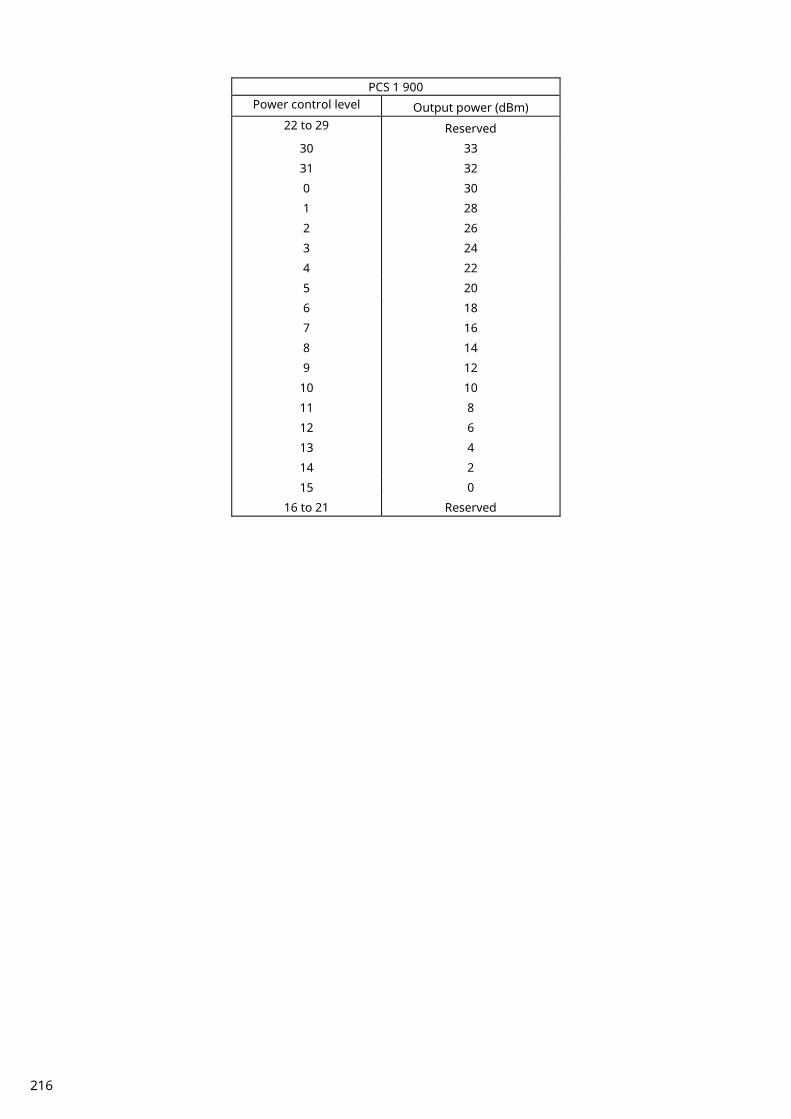
PCS 1 900 Power control level Output power (dBm)
22 to 29 Reserved
30 33
31 32
0 30
1 28
2 26
3 24
4 22
5 20
6 18
7 16
8 14
9 12
10 10
11 8
12 6
13 4
14 2
15 0
16 to 21 Reserved
216

2.13.4. Frequency Hopping Frequency hopping changes the communication channel between the base station and UE using a communication frame in the same band. Six hopping bands (P-GSM, E-GSM, R-GSM, GSM850, DCS1800, PCS1900) are supported. Also, up to 40 hopping channels can be set in one hopping band. Frequency hopping is performed to measure ARFCN set in Measure Channel & Frequency. A measurement example for 63CH is show below. 1. Execute PRESET to preset the parameters. 2. Execute FREQSETMODE BAND to set [Setting Mode] to [Band and Channel]. 3. Execute HOPFREQ P-GSM,2,63,123 to set [ARFCNs] to [2, 63, 123] for the Hopping Frequency Table P-GSM
Band. 4. Execute FREQHOP ON to set [Frequency Hopping] to [On]. 5. Execute BAND P-GSM to set [Hopping Band] to [P-GSM]. 6. Execute CHAN 2 to set [Measure Channel & Frequency] to [2]. 7. Connect using GSM. 8. Perform measurement. 9. Execute CHAN 63 to set [Measure Channel & Frequency] to [63]. 10. Perform measurement.
217

2.13.5. Multislot Power vs. Time Measurement The Multislot Power vs. Time Measurement measures the TX Power and Power vs. Time for multislot output from the mobile station (MS). Up to four slots can be measured according to the Uplink setting at the Multislot Configuration. This function can only be executed by remote command.
1. Execute MLTSLTCFG 2DL2UL to set [Multi Slot Configuration] to [2DL, 2UL], meaning 2 slot each for Downlink and Uplink.
2. Execute CS MCS5 to set [Coding Scheme] to [MCS-5]. 3. Connect at Test Mode A. 4. Execute CHMSPWR ,15,5 to change MS Power Level - [1st Slot] to [15], MS Power Level - [2nd Slot] to [5]. 5. Execute MPWR_REF to optimize the input level of the measurement slot. 6. Execute MEASOBJ 8PSK to set [Measuring Object] to [8PSK] (MEASOBJ MSNB when modulation method is
GMSK). 7. Execute MLTSLTVSTIME_MEAS ON to set [Multislot Power vs. time Measurement] to [On]. 8. Execute MLTSLTVSTIME_COUNT 60 to set [Multislot Power vs. time Measurement Count] to [60]. 9. Execute MPWR_LEADTM 1,1,-28.0 to set 1st slot - [Multislot Power vs. Time Offset (Leading Time 1)] to [-28.0] µs.
10. Execute MPWR_TRAILTM 1,1,542.8 to set 1st slot - [Multislot Power vs. Time Offset (Trailing Time 1)] to [-542.8] µs.
11. Execute MPWR_LEADTM 2,1,-28.0 to set 2nd slot - [Multislot Power vs. Time Offset (Leading Time 1)] to [-28.0] µs.
12. Execute MPWR_TRAILTM 2,1,542.8 to set 2nd slot - [Multislot Power vs. Time Offset (Trailing Time 1)] to [-542.8] µs.
13. Execute SWP to perform BLER measurement. 14. Execute MSTAT? to read measurement status. (0 is Normal termination.)
[1st slot measurement]
15. Execute AVG_MTXPWR? 1,DBM to read the 1st slot - Power measurement result. 16. Execute MAX_MPTLEAD? 1,1 to read the 1st slot - Leading Time 1 measurement result. 17. Execute MAX_MPTTRAIL? 1,1 to read the 1st slot - Trailing Time 1 measurement result.
[2nd slot measurement]
18. Execute AVG_MTXPWR? 2,DBM to read the 2nd slot - Power measurement result. 19. Execute MAX_MPTLEAD? 2,1 to read the 2nd slot - Leading Time 1 measurement result. 20. Execute MAX_MPTTRAIL? 2,1 to read the 2nd slot - Trailing Time 1 measurement result.
218

3. Audio Measurement
3.1. Specifications Table 3.1-1: W-CDMA/GSM Voice Codec Option Specification
Item Specification
Voice codec W-CDMA: AMR 12.2 kbps
GSM: EFR, AMR
Codec level adjustment
Encoder input gain: –3.00 to 3.00 dB, 0.01-dB steps
Handset microphone volume: 0, 1, 2, 3, 4, 5
Handset speaker volume: 0, 1, 2, 3, 4, 5
AF Output Frequency range: 30 Hz to 10 kHz, 1 Hz resolution
Setting range: 0 to 5 Vpeak (AF Output connector)
Setting resolution: 1 mV (≤5 Vpeak), 100 µV (≤500 mVpeak), 10 µV (≤50 mVpeak)
Accuracy: ±0.2 dB (≥10 mVpeak, ≥50 Hz), ±0.3 dB (≥10 mVpeak, <50 Hz)
Waveform distortion: ≤30 kHz band ≤–60 dB (≥500 mVpeak, ≤5 kHz), ≤–54 dB (≥70 mVpeak)
Output impedance: ≤1 Ω
Maximum output current: 100 mA
AF Input Frequency range: 50 Hz to 10 kHz
Input voltage range: 1 mVpeak to 5 Vpeak (AF Input connector)
Maximum allowable input voltage: 30 Vrms
Input impedance: 100 kΩ
Frequency measurement
Accuracy: ±(Reference oscillator accuracy +0.5 Hz)
Level measurement Accuracy: ±0.2 dB (≥10 mVpeak, ≥50 Hz) ±0.4 dB (≥1 mVpeak, ≥1 kHz)
SINAD Measurement Frequency: 1 kHz in ≤30 kHz band
≥60 dB (≥1000 mVpeak), ≥54 dB (>50 mVpeak), ≥46 dB (≥10 mVpeak)
Distortion measurement
Frequency: 1 kHz in ≤30 kHz band
≤–60 dB (≥1000 mVpeak), ≤–54 dB (>50 mVpeak), ≤–46 dB (≥10 mVpeak)
219
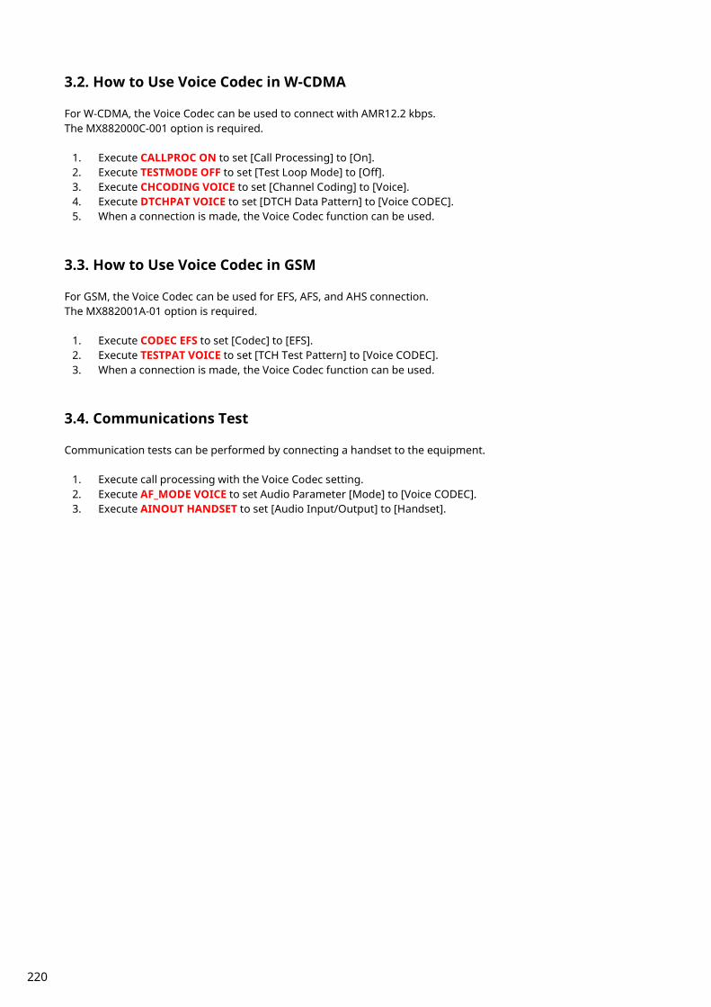
3.2. How to Use Voice Codec in W-CDMA For W-CDMA, the Voice Codec can be used to connect with AMR12.2 kbps. The MX882000C-001 option is required.
1. Execute CALLPROC ON to set [Call Processing] to [On]. 2. Execute TESTMODE OFF to set [Test Loop Mode] to [Off]. 3. Execute CHCODING VOICE to set [Channel Coding] to [Voice]. 4. Execute DTCHPAT VOICE to set [DTCH Data Pattern] to [Voice CODEC]. 5. When a connection is made, the Voice Codec function can be used.
3.3. How to Use Voice Codec in GSM For GSM, the Voice Codec can be used for EFS, AFS, and AHS connection. The MX882001A-01 option is required.
1. Execute CODEC EFS to set [Codec] to [EFS]. 2. Execute TESTPAT VOICE to set [TCH Test Pattern] to [Voice CODEC]. 3. When a connection is made, the Voice Codec function can be used.
3.4. Communications Test Communication tests can be performed by connecting a handset to the equipment.
1. Execute call processing with the Voice Codec setting. 2. Execute AF_MODE VOICE to set Audio Parameter [Mode] to [Voice CODEC]. 3. Execute AINOUT HANDSET to set [Audio Input/Output] to [Handset].
220

3.5. Tx Audio Measurement When a tone signal from the equipment AF Output is input to MIC (microphone), the UE encodes the voice signal and transmits it as the uplink signal. The equipment receives the uplink signal and inputs the decoded voice signal to the AF Analyzer to measure frequency, level and distortion rate.
1. Execute call processing with the Voice Codec setting. 2. Execute AF_MODE TXAUDIO to set Audio [Mode] to [TX Audio]. 3. Execute AF_FREQ 1000 to set Tone Generator (AF Output) - [Frequency] to [1000] Hz. 4. Execute AF_TGLVL 100 to set Tone Generator (AF Output) - [Level] to [100] mV (peak). 5. Execute AF_MEAS ON to set [Audio Measurement] to [On]. 6. Execute AF_AVG 5 to set [Average Count] of Audio Measurement to [5] times. 7. Execute SWP to perform Audio Measurement to Decoder Output signal. 8. Execute AVG_AFFREQ? to read the Frequency measurement result. 9. Execute AVG_TAFLVL? to read the Level measurement result.
10. Execute AVG_AFDSTN_DB? to read the distortion rate measurement result. When changing the system, set AF Mode to Voice Codec.
VoiceCoder
VoiceDecoder
DAC Demodu-lation
ChannelDecode
BB/RF
VOCODERAF
Generator
AFAnalyzer
MT8820A
MS
MIC
AF output
221

3.6. Rx Audio Measurement The equipment encodes the tone signal generated by the AF Generator and sends it as the downlink signal. The UE decodes the received downlink signal and outputs the voice signal from the speaker. The voice signal is input to the equipment AF Input and the AF Analyzer measures the frequency, level and distortion rate.
1. Execute call processing with the Voice Codec setting. 2. Execute AF_MODE RXAUDIO to set Audio Parameter [Mode] to [RX Audio]. 3. Execute AF_FREQ 1000 to set Tone Generator (Encoder Input) - [Frequency] to [1000] Hz. 4. Execute AF_EILVL -6 to set [Tone Generator (Encoder Input) - [Encoder Input Level] to [–6] dB. 5. Execute AF_IRANGE 500 to set Audio Analyzer (AF Input) - [Input Level Range] to [500 mV(peak)]. 6. Execute AF_MEAS ON to set [Audio Measurement] to [On]. 7. Execute AF_AVG 5 to set [Average Count] of Audio Measurement to [5] times. 8. Execute SWP to perform Audio Measurement of the AF Input signal. 9. Execute AVG_AFFREQ? to read the Frequency measurement result.
10. Execute AVG_RAFLVL? to read the Level measurement result. 11. Execute AVG_AFDSTN_DB? to read the distortion rate measurement result. When changing the system, set AF Mode to Voice Codec.
VoiceCoder
VoiceDecoderDAC
ChannelEncode
Modulation
BB/RF
VOCODERAF
Generator
AFAnalyzer
MT8820A
MS
Speaker
AF input
222

3.7. General-purpose Audio Generator/Analyzer The equipment can be used as a general-purpose audio generator/analyzer.
1. Execute AF_MODE GENERAL to set Audio Parameter [Mode] to [General Audio]. Audio Generator Function
2. Execute AF_FREQ 1000 to set Tone Generator - [Frequency] to [1000] Hz. 3. Execute AF_TGLVL 1000 to set Tone Generator - [Level] to [–1000] mV/(peak). 4. The AF Output outputs a 1 kHz/1000 mV tone signal.
Audio Analyzer Function
5. Execute AF_MEAS ON to set [Audio Measurement] to [On]. 6. Execute AF_AVG 5 to set [Average Count] of Audio Measurement to [5] times. 7. Execute SWP to perform Audio Measurement of the AF Input signal. 8. Execute AVG_AFFREQ? to read the Frequency measurement result. 9. Execute AVG_RAFLVL? to read the Level measurement result.
10. Execute AVG_AFDSTN_DB? to read the distortion rate measurement result. When changing the system, set AF Mode to Voice Codec.
223
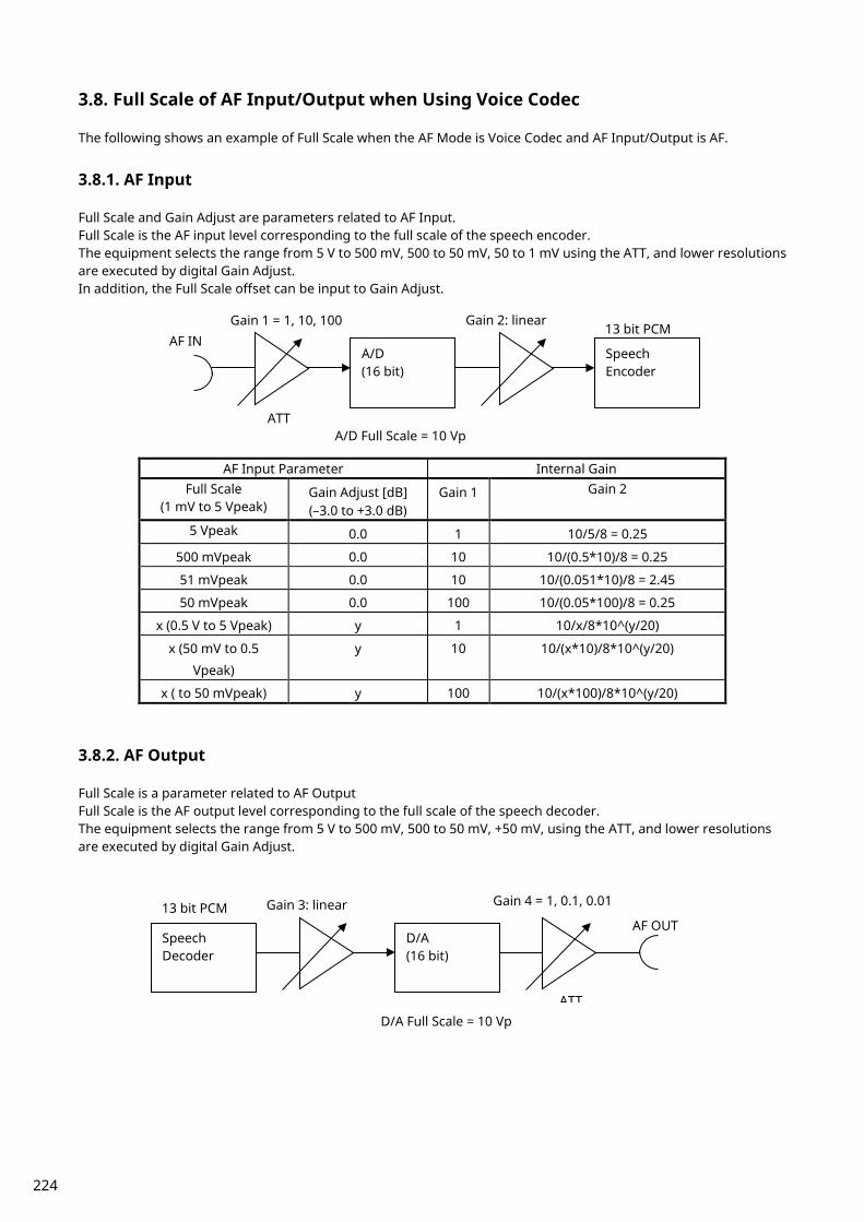
3.8. Full Scale of AF Input/Output when Using Voice Codec The following shows an example of Full Scale when the AF Mode is Voice Codec and AF Input/Output is AF.
3.8.1. AF Input Full Scale and Gain Adjust are parameters related to AF Input. Full Scale is the AF input level corresponding to the full scale of the speech encoder. The equipment selects the range from 5 V to 500 mV, 500 to 50 mV, 50 to 1 mV using the ATT, and lower resolutions are executed by digital Gain Adjust. In addition, the Full Scale offset can be input to Gain Adjust.
AF Input Parameter Internal Gain Full Scale
(1 mV to 5 Vpeak) Gain Adjust [dB] (–3.0 to +3.0 dB)
Gain 1 Gain 2
5 Vpeak 0.0 1 10/5/8 = 0.25
500 mVpeak 0.0 10 10/(0.5*10)/8 = 0.25
51 mVpeak 0.0 10 10/(0.051*10)/8 = 2.45
50 mVpeak 0.0 100 10/(0.05*100)/8 = 0.25
x (0.5 V to 5 Vpeak) y 1 10/x/8*10^(y/20)
x (50 mV to 0.5
Vpeak)
y 10 10/(x*10)/8*10^(y/20)
x ( to 50 mVpeak) y 100 10/(x*100)/8*10^(y/20)
3.8.2. AF Output Full Scale is a parameter related to AF Output Full Scale is the AF output level corresponding to the full scale of the speech decoder. The equipment selects the range from 5 V to 500 mV, 500 to 50 mV, +50 mV, using the ATT, and lower resolutions are executed by digital Gain Adjust.
13 bit PCM A/D
(16 bit)
Speech Encoder
AF IN
Gain 1 = 1, 10, 100
Gain 2: linear
A/D Full Scale = 10 Vp
ATT
13 bit PCM Speech Decoder
D/A (16 bit)
AF OUT
Gain 3: linear
Gain 4 = 1, 0.1, 0.01
D/A Full Scale = 10 Vp ATT
224

AF Output Parameter Internal Gain
Full Scale ( to 5 Vpeak)
Gain 3 Gain 4
5 Vpeak 5/10*8 = 4 1
500 mVpeak 0.5/(10*0.1)*8 = 4 0.1
51 mVpeak 0.051/(10*0.1)*8 = 0.4 0.1
50 mVpeak 0.05/(10*0.01)*8 = 4 0.01
x (0.5 V to 5 Vpeak) x/10*8 1
x (50 mV to 0.5 Vpeak) x/(10*0.1)*8 0.1
x ( to 50 mVpeak) x/(10*0.01)*8 0.01
225
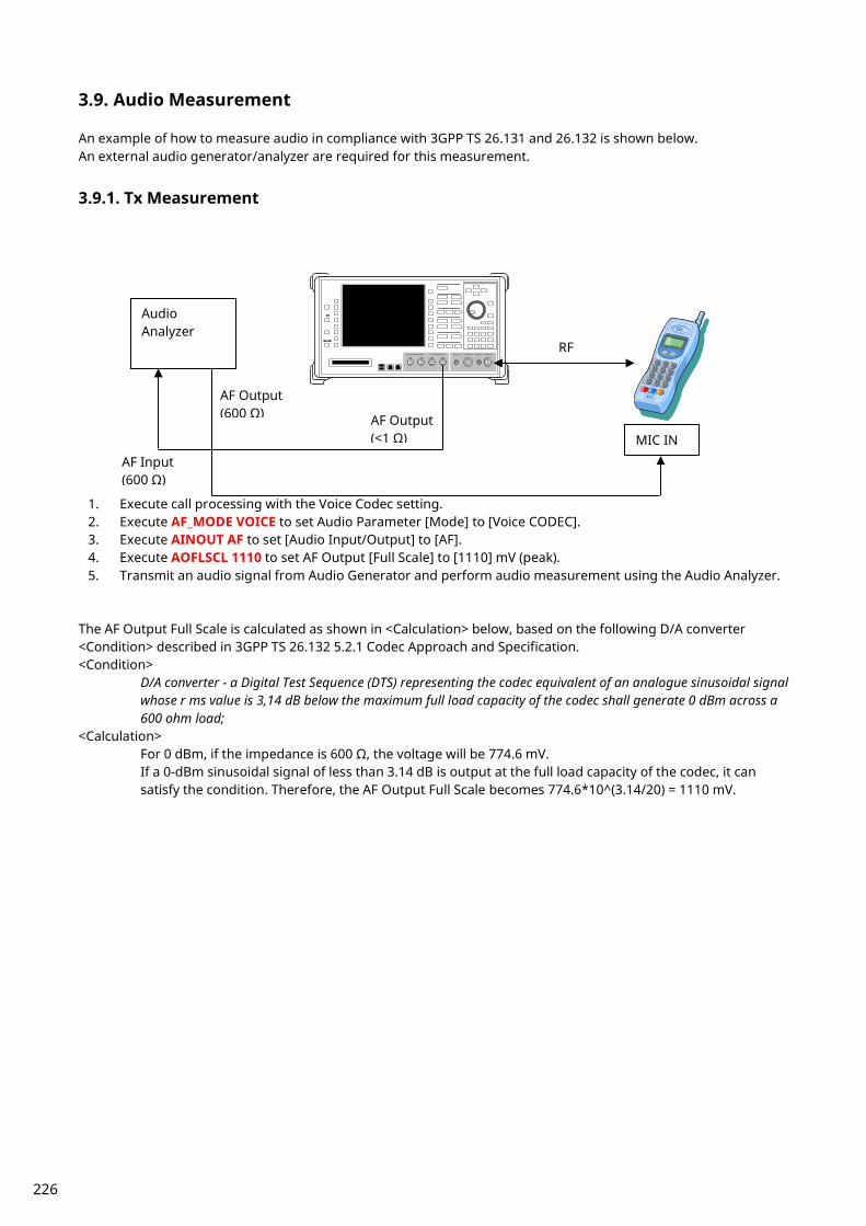
3.9. Audio Measurement An example of how to measure audio in compliance with 3GPP TS 26.131 and 26.132 is shown below. An external audio generator/analyzer are required for this measurement.
3.9.1. Tx Measurement
1. Execute call processing with the Voice Codec setting. 2. Execute AF_MODE VOICE to set Audio Parameter [Mode] to [Voice CODEC]. 3. Execute AINOUT AF to set [Audio Input/Output] to [AF]. 4. Execute AOFLSCL 1110 to set AF Output [Full Scale] to [1110] mV (peak). 5. Transmit an audio signal from Audio Generator and perform audio measurement using the Audio Analyzer.
The AF Output Full Scale is calculated as shown in <Calculation> below, based on the following D/A converter <Condition> described in 3GPP TS 26.132 5.2.1 Codec Approach and Specification. <Condition>
D/A converter - a Digital Test Sequence (DTS) representing the codec equivalent of an analogue sinusoidal signal whose r ms value is 3,14 dB below the maximum full load capacity of the codec shall generate 0 dBm across a 600 ohm load;
<Calculation> For 0 dBm, if the impedance is 600 Ω, the voltage will be 774.6 mV. If a 0-dBm sinusoidal signal of less than 3.14 dB is output at the full load capacity of the codec, it can satisfy the condition. Therefore, the AF Output Full Scale becomes 774.6*10^(3.14/20) = 1110 mV.
Audio Analyzer
AF Input (600 Ω)
MIC IN
AF Output (600 Ω)
AF Output (<1 Ω)
RF
226

3.9.2. Rx Test
1. Execute call processing with the Voice Codec setting. 2. Execute AF_MODE VOICE to set Audio Parameter [Mode] to [Voice CODEC]. 3. Execute AINOUT AF to set [Audio Input/Output] to [AF]. 4. Execute AIFLSCL 2210 to set AF Input [Full Scale] to [2210] mV (peak). 5. Send an audio signal from the Audio Generator and perform audio measurement using the Audio Analyzer.
The AF Input Full Scale is calculated as shown in <Calculation> below, based on following A/D converter <Condition> described in 3GPP TS 26.132 5.2.1 Codec Approach and Specification. <Condition>
A/D converter - a 0 dBm signal generated from a 600 Ω source shall give the digital test sequence (DTS) representing the codec equivalent of an analogue sinusoidal signal whose R MS value is 3.14 dB below the maximum full-load capacity of the codec.
<Calculation> Regarding 0 dBm, if the impedance is 600 Ω, the voltage will be 774.6 mV. However, the input impedance of the MT8820A is 100 kΩ, so the input voltage will be 774.6*2 = 1549 mV. To meet the condition, the 0-dBm sinusoidal signal shall be 3.14 dB below the full load capacity of the codec. Therefore, the AF Input Full Scale becomes 1549*10^(3.14/20) = 2220 mV.
Audio Analyzer
AF Output (600 Ω) SPEAKER OUT
AF Input (600 Ω)
AF Input (100 kΩ)
RF
227
Appendix A Inner Loop Power Control Measurement(Previous procedure) The following measurement uses Inner Loop Power Control measurement on Time Domain Measurement screen. Due to limits on the equipment dynamic range (40 dB), Test Steps E, F, G, and H cannot be measured simultaneously, so measurement must be performed twice by changing the Input Level.
1. Execute SCRSEL TDMEAS to display the Time Domain Measurement screen. 2. Execute MEASOBJ ILPC to set [Measurement Object] to [Inner Loop Power Control]. 3. Execute SLOTLIST ON to display the slot list. 4. Execute REGSLOTLIST 0-59 to register Slot0~Slot59 for the slot list. 5. Execute TIMSPAN 40.0MS to set [Time Span] of Time Domain measurement to [40.0] ms. 6. Execute OLVL -93 to set [Output Level] to [–93] dBm. 7. Execute TPCALGO 2 to set [Power Control Algorithm] to [Algorithm 2]. 8. Execute TPCSTEP 1 to set [TPC Step Size] to [1 dB]. 9. Execute TDM_RRC OFF to set [RRC Filter] to [Off].
10. Execute VFILTLEN 0.1US to set [Video Filter Length] to [0.1] µs. 11. Connect using Test Loop Mode1.
A.1 Inner Loop Power Control Parameter Inner Loop Power Control Parameter of Call Processing Parameter is the steady-state setting of the TPC command. When Power Control Bit Pattern is set to [Inner Loop Power Control], the TPC command is sent automatically to adjust UE output power to Input Level. In the case of Inner Loop Power Control Parameter of Time Domain Parameter, the TPC command between Slot 0 and the specified Slot is set only when Measurement Object of Time Domain Measurement is measured using Inner Loop Power Control. After sending the specified number of slots, the TPC command set at Call Processing Parameter is sent. Sometimes, at Inner Loop Power Control measurement, the UE output power must be set lower (or higher) than [Input Level] before measurement. Examples of how to set Input Level to +30 dBm and UE output power to -10 dBm are shown below.
1. Execute TPCPAT ILPC to set [Power Control Bit Pattern] to [Inner Loop Power Control]. 2. Execute ILVL -10.0 to set [Input Level] to [–10.0] dBm. 3. Wait until the UE power is –10.0 dBm. 4. Execute TPCPAT ALT to set [Power Control Bit Pattern] to [Alternate]. 5. Execute ILVL 30.0 to set [Input Level] to [+30.0] dBm.
228
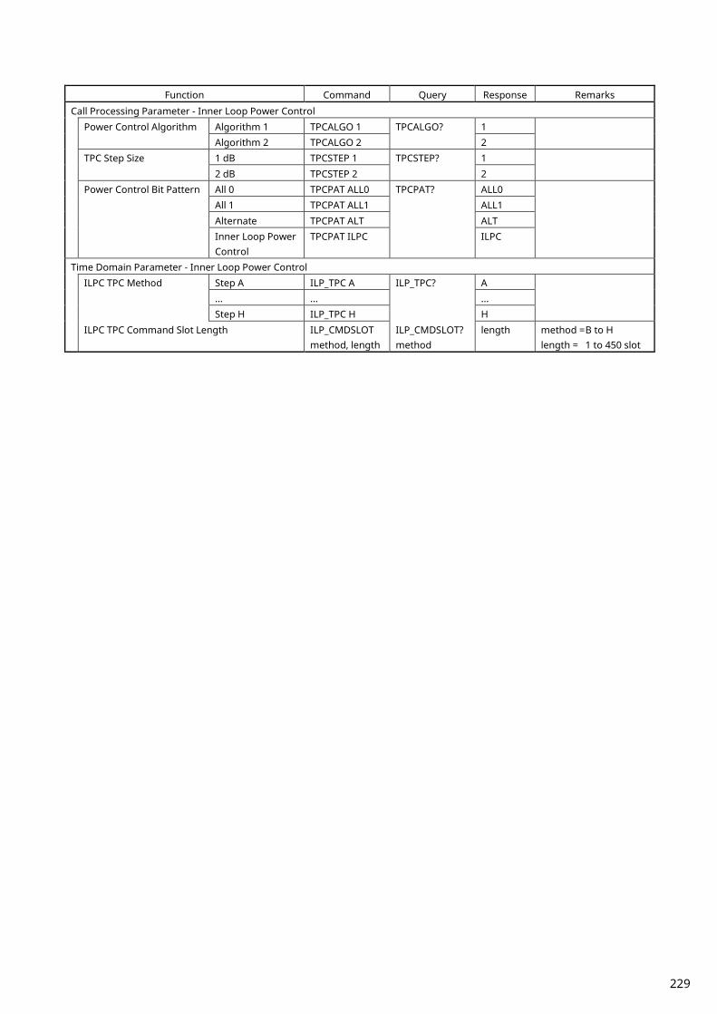
Function Command Query Response Remarks
Call Processing Parameter - Inner Loop Power Control Power Control Algorithm Algorithm 1 TPCALGO 1 TPCALGO? 1
Algorithm 2 TPCALGO 2 2 TPC Step Size 1 dB TPCSTEP 1 TPCSTEP? 1
2 dB TPCSTEP 2 2 Power Control Bit Pattern All 0 TPCPAT ALL0 TPCPAT? ALL0
All 1 TPCPAT ALL1 ALL1 Alternate TPCPAT ALT ALT Inner Loop Power Control
TPCPAT ILPC ILPC
Time Domain Parameter - Inner Loop Power Control ILPC TPC Method Step A ILP_TPC A ILP_TPC? A
... ... ... Step H ILP_TPC H H
ILPC TPC Command Slot Length ILP_CMDSLOT method, length
ILP_CMDSLOT? method
length method = B to H length = 1 to 450 slot
229

A.2 5.4.2 Inner Loop Power Control in Uplink [Step A] 23. Execute ILP_TPC A to set [TPC Method] to [Step A]. 24. Execute TPCALGO 2 to set [Power Control Algorithm] to [Algorithm 2]. 25. Execute TPCSTEP 1 to set [TPC Step Size] to [1 dB]. 26. Execute TPCPAT ILPC to set [Power Control Bit Pattern] to [Inner Loop Power Control]. 27. Execute ILVL -10.0 to set [Input Level] to [–10.0] dBm. 28. Execute TPCPAT ALT to set [Power Control Bit Pattern] to [Alternate]. 29. Execute ILVL 0.0 to set [Input Level] to [0.0] dBm. 30. Execute SWP to perform measurement. 31. Execute SLOT_PWR? ALL to read the measurement result.
230

[Step B] 32. Execute ILP_TPC B to set [TPC Method] to [Step B]. 33. Execute TPCALGO 2 to set [Power Control Algorithm] to [Algorithm 2]. 34. Execute TPCSTEP 1 to set [TPC Step Size] to [1 dB]. 35. Execute TPCPAT ALT to set [Power Control Bit Pattern] to [Alternate]. 36. Execute ILVL 0.0 to set [Input Level] to [0.0] dBm. 37. Execute SWP to perform measurement. 38. Execute SLOT_PWR? ALL to read the measurement result.
[Step C] 39. Execute ILP_TPC C to set [TPC Method] to [Step C]. 40. Execute TPCALGO 2 to set [Power Control Algorithm] to [Algorithm 2]. 41. Execute TPCSTEP 1 to set [TPC Step Size] to [1 dB]. 42. Execute TPCPAT ALT to set [Power Control Bit Pattern] to [Alternate]. 43. Execute ILVL 0.0 to set [Input Level] to [0.0] dBm. 44. Execute SWP to perform measurement. 45. Execute SLOT_PWR? ALL to read the measurement result.
231

[Step D] 46. Execute ILP_TPC D to set [TPC Method] to [Step D]. 47. Execute TPCALGO 1 to set [Power Control Algorithm] to [Algorithm 1]. 48. Execute TPCSTEP 1 to set [TPC Step Size] to [1 dB]. 49. Execute TPCPAT ALT to set [Power Control Bit Pattern] to [Alternate]. 50. Execute ILVL 25.0 to set [Input Level] to [+25.0] dBm. 51. Execute SWP to perform the measurement. 52. Execute SLOT_PWR? ALL to read the measurement result.
[Step E 1] 53. Execute ILP_TPC E to set [TPC Method] to [Step E]. 54. Execute ILP_CMDSLOT E,40 to set [Length] of Test Step E to [40] Slot. 55. Execute TPCALGO 1 to set [Power Control Algorithm] to [Algorithm 1]. 56. Execute TPCSTEP 1 to set [TPC Step Size] to [1 dB]. 57. Execute TPCPAT ALT to set [Power Control Bit Pattern] to [Alternate]. 58. Execute ILVL 25.0 to set [Input Level] to [+25.0] dBm. 59. Execute SWP to perform measurement. 60. Execute SLOT_PWR? ALL to read the measurement result.
232
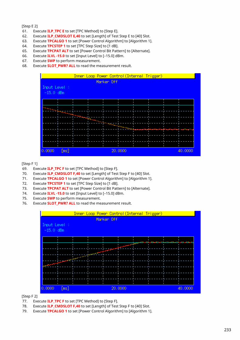
[Step E 2] 61. Execute ILP_TPC E to set [TPC Method] to [Step E]. 62. Execute ILP_CMDSLOT E,40 to set [Length] of Test Step E to [40] Slot. 63. Execute TPCALGO 1 to set [Power Control Algorithm] to [Algorithm 1]. 64. Execute TPCSTEP 1 to set [TPC Step Size] to [1 dB]. 65. Execute TPCPAT ALT to set [Power Control Bit Pattern] to [Alternate]. 66. Execute ILVL -15.0 to set [Input Level] to [–15.0] dBm. 67. Execute SWP to perform measurement. 68. Execute SLOT_PWR? ALL to read the measurement result.
[Step F 1] 69. Execute ILP_TPC F to set [TPC Method] to [Step F]. 70. Execute ILP_CMDSLOT F,40 to set [Length] of Test Step F to [40] Slot. 71. Execute TPCALGO 1 to set [Power Control Algorithm] to [Algorithm 1]. 72. Execute TPCSTEP 1 to set [TPC Step Size] to [1 dB]. 73. Execute TPCPAT ALT to set [Power Control Bit Pattern] to [Alternate]. 74. Execute ILVL -15.0 to set [Input Level] to [–15.0] dBm. 75. Execute SWP to perform measurement. 76. Execute SLOT_PWR? ALL to read the measurement result.
[Step F 2] 77. Execute ILP_TPC F to set [TPC Method] to [Step F]. 78. Execute ILP_CMDSLOT F,40 to set [Length] of Test Step F to [40] Slot. 79. Execute TPCALGO 1 to set [Power Control Algorithm] to [Algorithm 1].
233
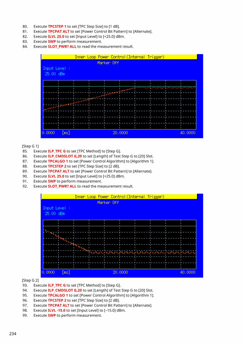
80. Execute TPCSTEP 1 to set [TPC Step Size] to [1 dB]. 81. Execute TPCPAT ALT to set [Power Control Bit Pattern] to [Alternate]. 82. Execute ILVL 25.0 to set [Input Level] to [+25.0] dBm. 83. Execute SWP to perform measurement. 84. Execute SLOT_PWR? ALL to read the measurement result.
[Step G 1] 85. Execute ILP_TPC G to set [TPC Method] to [Step G]. 86. Execute ILP_CMDSLOT G,20 to set [Length] of Test Step G to [20] Slot. 87. Execute TPCALGO 1 to set [Power Control Algorithm] to [Algorithm 1]. 88. Execute TPCSTEP 2 to set [TPC Step Size] to [2 dB]. 89. Execute TPCPAT ALT to set [Power Control Bit Pattern] to [Alternate]. 90. Execute ILVL 25.0 to set [Input Level] to [+25.0] dBm. 91. Execute SWP to perform measurement. 92. Execute SLOT_PWR? ALL to read the measurement result.
[Step G 2] 93. Execute ILP_TPC G to set [TPC Method] to [Step G]. 94. Execute ILP_CMDSLOT G,20 to set [Length] of Test Step G to [20] Slot. 95. Execute TPCALGO 1 to set [Power Control Algorithm] to [Algorithm 1]. 96. Execute TPCSTEP 2 to set [TPC Step Size] to [2 dB]. 97. Execute TPCPAT ALT to set [Power Control Bit Pattern] to [Alternate]. 98. Execute ILVL -15.0 to set [Input Level] to [–15.0] dBm. 99. Execute SWP to perform measurement.
234
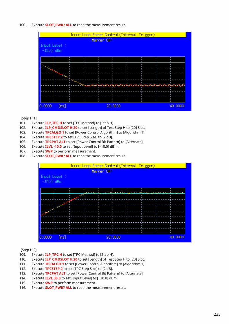
100. Execute SLOT_PWR? ALL to read the measurement result.
[Step H 1]
101. Execute ILP_TPC H to set [TPC Method] to [Step H]. 102. Execute ILP_CMDSLOT H,20 to set [Length] of Test Step H to [20] Slot. 103. Execute TPCALGO 1 to set [Power Control Algorithm] to [Algorithm 1]. 104. Execute TPCSTEP 2 to set [TPC Step Size] to [2 dB]. 105. Execute TPCPAT ALT to set [Power Control Bit Pattern] to [Alternate]. 106. Execute ILVL -10.0 to set [Input Level] to [–10.0] dBm. 107. Execute SWP to perform measurement. 108. Execute SLOT_PWR? ALL to read the measurement result.
[Step H 2]
109. Execute ILP_TPC H to set [TPC Method] to [Step H]. 110. Execute ILP_CMDSLOT H,20 to set [Length] of Test Step H to [20] Slot. 111. Execute TPCALGO 1 to set [Power Control Algorithm] to [Algorithm 1]. 112. Execute TPCSTEP 2 to set [TPC Step Size] to [2 dB]. 113. Execute TPCPAT ALT to set [Power Control Bit Pattern] to [Alternate]. 114. Execute ILVL 30.0 to set [Input Level] to [+30.0] dBm. 115. Execute SWP to perform measurement. 116. Execute SLOT_PWR? ALL to read the measurement result.
235

236
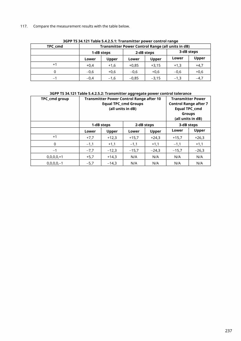
117. Compare the measurement results with the table below.
3GPP TS 34.121 Table 5.4.2.5.1: Transmitter power control range TPC_cmd Transmitter Power Control Range (all units in dB)
1-dB steps 2-dB steps 3-dB steps
Lower Upper Lower Upper Lower Upper
+1 +0,4 +1,6 +0,85 +3,15 +1,3 +4,7
0 −0,6 +0,6 −0,6 +0,6 −0,6 +0,6
−1 −0,4 −1,6 −0,85 −3,15 −1,3 −4,7
3GPP TS 34.121 Table 5.4.2.5.2: Transmitter aggregate power control tolerance TPC_cmd group Transmitter Power Control Range after 10
Equal TPC_cmd Groups (all units in dB)
Transmitter Power Control Range after 7
Equal TPC_cmd Groups
(all units in dB) 1-dB steps 2-dB steps 3-dB steps Lower Upper Lower Upper Lower Upper
+1 +7,7 +12,3 +15,7 +24,3 +15,7 +26,3
0 −1,1 +1,1 −1,1 +1,1 −1,1 +1,1
−1 −7,7 −12,3 −15,7 −24,3 −15,7 −26,3
0,0,0,0,+1 +5,7 +14,3 N/A N/A N/A N/A
0,0,0,0,−1 −5,7 −14,3 N/A N/A N/A N/A
237
A.3 How to Combine Segmentations at Step E, F, G, H of Inner Loop Power Control
Due to dynamic range limits, each Test Step E, F, G and H must be performed twice at different Input Levels. See the following explanations to combine the first and second Slot List. Before the first measurement, set [Power Control Bit Pattern] to [Alternate], so the [Power Control Bit Pattern] is [Alternate] also after the measurement. Because the first and last bits are not fixed, there are four Alternate Patterns sent between combined segmentation 0,1, …,1,0,0,1,…,0,1,1,0,…,1,0,1,0,…,0,1. Combination must be performed by considering “the sum of Bit number 0 is larger than Bit number 1,” “the sum of Bit number 0 and 1 are equal,” “the sum of Bit number 0 is smaller than Bit number 1.” An example of Test StepE is shown below.
238
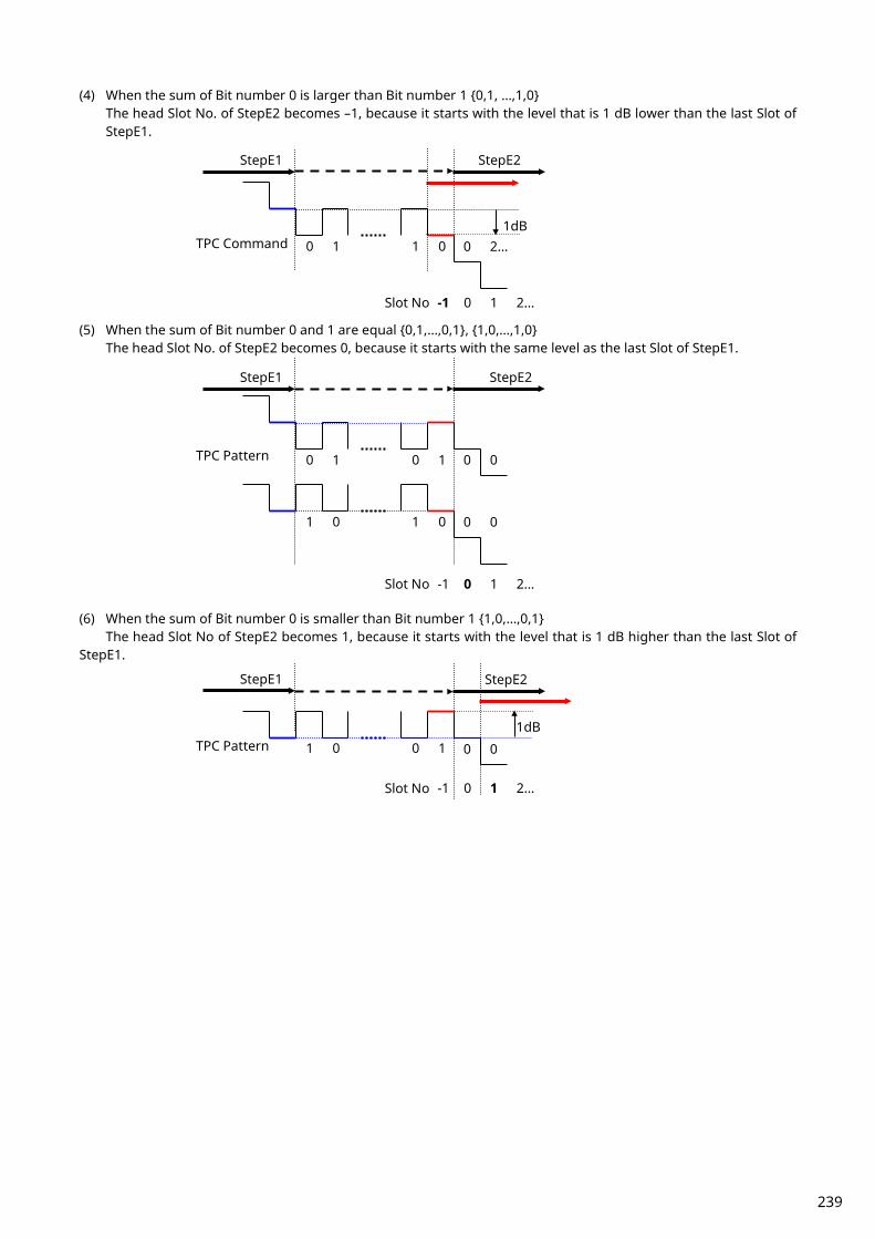
(4) When the sum of Bit number 0 is larger than Bit number 1 0,1, …,1,0 The head Slot No. of StepE2 becomes –1, because it starts with the level that is 1 dB lower than the last Slot of StepE1.
(5) When the sum of Bit number 0 and 1 are equal 0,1,…,0,1, 1,0,…,1,0
The head Slot No. of StepE2 becomes 0, because it starts with the same level as the last Slot of StepE1. (6) When the sum of Bit number 0 is smaller than Bit number 1 1,0,…,0,1
The head Slot No of StepE2 becomes 1, because it starts with the level that is 1 dB higher than the last Slot of StepE1.
0 1 1 0
StepE1
StepE2
0 1 0 1
1 0 1 0
-1 0 Slot No 1 2…
TPC Command
-1 0 1 2… Slot No
0 1 1 0
-1 0 1 2… Slot No
0 2…
0 0
0 0
0 0 TPC Pattern
TPC Pattern
StepE1
StepE2
1dB
StepE2
1dB
StepE1
239
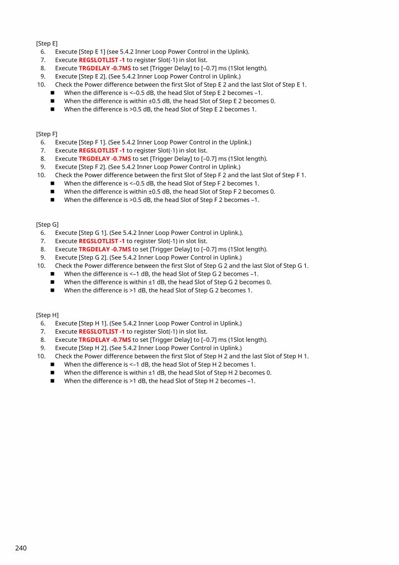
[Step E] 6. Execute [Step E 1] (see 5.4.2 Inner Loop Power Control in the Uplink). 7. Execute REGSLOTLIST -1 to register Slot(-1) in slot list. 8. Execute TRGDELAY -0.7MS to set [Trigger Delay] to [–0.7] ms (1Slot length). 9. Execute [Step E 2]. (See 5.4.2 Inner Loop Power Control in Uplink.)
10. Check the Power difference between the first Slot of Step E 2 and the last Slot of Step E 1. When the difference is <–0.5 dB, the head Slot of Step E 2 becomes –1. When the difference is within ±0.5 dB, the head Slot of Step E 2 becomes 0. When the difference is >0.5 dB, the head Slot of Step E 2 becomes 1.
[Step F]
6. Execute [Step F 1]. (See 5.4.2 Inner Loop Power Control in the Uplink.) 7. Execute REGSLOTLIST -1 to register Slot(-1) in slot list. 8. Execute TRGDELAY -0.7MS to set [Trigger Delay] to [–0.7] ms (1Slot length). 9. Execute [Step F 2]. (See 5.4.2 Inner Loop Power Control in Uplink.)
10. Check the Power difference between the first Slot of Step F 2 and the last Slot of Step F 1. When the difference is <–0.5 dB, the head Slot of Step F 2 becomes 1. When the difference is within ±0.5 dB, the head Slot of Step F 2 becomes 0. When the difference is >0.5 dB, the head Slot of Step F 2 becomes –1.
[Step G]
6. Execute [Step G 1]. (See 5.4.2 Inner Loop Power Control in Uplink.). 7. Execute REGSLOTLIST -1 to register Slot(-1) in slot list. 8. Execute TRGDELAY -0.7MS to set [Trigger Delay] to [–0.7] ms (1Slot length). 9. Execute [Step G 2]. (See 5.4.2 Inner Loop Power Control in Uplink.)
10. Check the Power difference between the first Slot of Step G 2 and the last Slot of Step G 1. When the difference is <–1 dB, the head Slot of Step G 2 becomes –1. When the difference is within ±1 dB, the head Slot of Step G 2 becomes 0. When the difference is >1 dB, the head Slot of Step G 2 becomes 1.
[Step H]
6. Execute [Step H 1]. (See 5.4.2 Inner Loop Power Control in Uplink.) 7. Execute REGSLOTLIST -1 to register Slot(-1) in slot list. 8. Execute TRGDELAY -0.7MS to set [Trigger Delay] to [–0.7] ms (1Slot length). 9. Execute [Step H 2]. (See 5.4.2 Inner Loop Power Control in Uplink.)
10. Check the Power difference between the first Slot of Step H 2 and the last Slot of Step H 1. When the difference is <–1 dB, the head Slot of Step H 2 becomes 1. When the difference is within ±1 dB, the head Slot of Step H 2 becomes 0. When the difference is >1 dB, the head Slot of Step H 2 becomes –1.
240

Note
241

Anritsu Company 1155 East Collins Blvd., Suite 100, Richardson, TX 75081, U.S.A.Toll Free: 1-800-267-4878Phone: +1-972-644-1777Fax: +1-972-671-1877
• CanadaAnritsu Electronics Ltd.700 Silver Seven Road, Suite 120, Kanata, Ontario K2V 1C3, CanadaPhone: +1-613-591-2003 Fax: +1-613-591-1006
• Brazil Anritsu Eletronica Ltda.
Phone: +55-11-3283-2511Fax: +55-11-3288-6940
• MexicoAnritsu Company, S.A. de C.V.Av. Ejército Nacional No. 579 Piso 9, Col. Granada11520 México, D.F., MéxicoPhone: +52-55-1101-2370Fax: +52-55-5254-3147
• United KingdomAnritsu EMEA Ltd. 200 Capability Green, Luton, Bedfordshire, LU1 3LU, U.K.Phone: +44-1582-433200 Fax: +44-1582-731303
• FranceAnritsu S.A. 12 avenue du Québec, Bâtiment Iris 1- Silic 612,91140 VILLEBON SUR YVETTE, FrancePhone: +33-1-60-92-15-50Fax: +33-1-64-46-10-65
• GermanyAnritsu GmbHNemetschek Haus, Konrad-Zuse-Platz 1 81829 München, Germany Phone: +49-89-442308-0Fax: +49-89-442308-55
• ItalyAnritsu S.r.l.Via Elio Vittorini 129, 00144 Roma, ItalyPhone: +39-6-509-9711 Fax: +39-6-502-2425
• SwedenAnritsu ABKistagången 20B, 164 40 KISTA, SwedenPhone: +46-8-534-707-00Fax: +46-8-534-707-30
• FinlandAnritsu ABTeknobulevardi 3-5, FI-01530 VANTAA, FinlandPhone: +358-20-741-8100Fax: +358-20-741-8111
• DenmarkAnritsu A/SKay Fiskers Plads 9, 2300 Copenhagen S, DenmarkPhone: +45-7211-2200Fax: +45-7211-2210
• RussiaAnritsu EMEA Ltd. Representation Office in RussiaTverskaya str. 16/2, bld. 1, 7th floor.Moscow, 125009, RussiaPhone: +7-495-363-1694Fax: +7-495-935-8962
• SpainAnritsu EMEA Ltd. Representation Office in SpainEdificio Cuzco IV, Po. de la Castellana, 141, Pta. 828046, Madrid, SpainPhone: +34-915-726-761Fax: +34-915-726-621
• United Arab EmiratesAnritsu EMEA Ltd. Dubai Liaison Office
• P.R. China (Shanghai)Anritsu (China) Co., Ltd.Room 2701-2705, Tower A, New Caohejing International Business CenterNo. 391 Gui Ping Road Shanghai, 200233, P.R. ChinaPhone: +86-21-6237-0898Fax: +86-21-6237-0899
• P.R. China (Hong Kong)Anritsu Company Ltd.Unit 1006-7, 10/F., Greenfield Tower, Concordia Plaza,No. 1 Science Museum Road, Tsim Sha Tsui East, Kowloon, Hong Kong, P.R. ChinaPhone: +852-2301-4980Fax: +852-2301-3545
• JapanAnritsu Corporation
Phone: +81-46-296-6509Fax: +81-46-225-8359
8-5, Tamura-cho, Atsugi-shi, Kanagawa, 243-0016 Japan
• KoreaAnritsu Corporation, Ltd.5FL, 235 Pangyoyeok-ro, Bundang-gu, Seongnam-si, Gyeonggi-do, 13494 KoreaPhone: +82-31-696-7750Fax: +82-31-696-7751
• AustraliaAnritsu Pty. Ltd.
Phone: +61-3-9558-8177Fax: +61-3-9558-8255
• TaiwanAnritsu Company Inc.7F, No. 316, Sec. 1, NeiHu Rd., Taipei 114, TaiwanPhone: +886-2-8751-1816Fax: +886-2-8751-1817
1603
Printed on Recycled Paper
• SingaporeAnritsu Pte. Ltd.11 Chang Charn Road, #04-01, Shriro HouseSingapore 159640Phone: +65-6282-2400Fax: +65-6282-2533
• IndiaAnritsu India Private Limited2nd & 3rd Floor, #837/1, Binnamangla 1st Stage,Indiranagar, 100ft Road, Bangalore - 560038, IndiaPhone: +91-80-4058-1300Fax: +91-80-4058-1301
Specifications are subject to change without notice.
• United States
Unit 20, 21-35 Ricketts Road, Mount Waverley, Victoria 3149, Australia
902, Aurora Tower,P O Box: 500311- Dubai Internet CityDubai, United Arab EmiratesPhone: +971-4-3758479Fax: +971-4-4249036
Praça Amadeu Amaral, 27 - 1 Andar01327-010 - Bela Vista - Sao Paulo - SPBrazil
Printed in Japan 2016-6 MG No. MT8820B/C/21C-E-F-1-(2.00)