application notes for configuring the cox communications
TRANSCRIPT

CTM; Reviewed:
SPOC 10/14/2013
Solution & Interoperability Test Lab Application Notes
©2013 Avaya Inc. All Rights Reserved.
1 of 74
CoxC63S63SBCE62
Avaya Solution & Interoperability Test Lab
Application Notes for Configuring the Cox Communications
SIP Trunking Service with Avaya Aura® Communication
Manager Evolution Server 6.3, Avaya Aura® Session
Manager 6.3 and Avaya Session Border Controller for
Enterprise 6.2 – Issue 1.0
Abstract
These Application Notes describe the steps to configure Session Initiation Protocol (SIP)
Trunking between the Cox Communications SIP Trunking Service and an Avaya SIP-enabled
enterprise solution. The Avaya solution consists of Avaya Aura® Session Manager 6.3,
Avaya Aura® Communication Manager Evolution Server 6.3, Avaya Session Border
Controller for Enterprise 6.2 and various Avaya endpoints. Cox Communications is a member
of the Avaya DevConnect Service Provider program.
Information in these Application Notes has been obtained through DevConnect compliance
testing and additional technical discussions. Testing was conducted via the DevConnect
Program at the Avaya Solution and Interoperability Test Lab.

CTM; Reviewed:
SPOC 10/14/2013
Solution & Interoperability Test Lab Application Notes
©2013 Avaya Inc. All Rights Reserved.
2 of 74
CoxC63S63SBCE62
1. Introduction These Application Notes describe the steps to configure Session Initiation Protocol (SIP)
Trunking between the Cox Communications SIP Trunking Service and an Avaya SIP-enabled
enterprise solution. The Avaya solution consists of Avaya Aura® Session Manager 6.3, Avaya
Aura® Communication Manager Evolution Server 6.3, Avaya Session Border Controller for
Enterprise 6.2 and various Avaya endpoints. In addition, Avaya Aura® System Manager 6.3 is
used to configure Avaya Aura® Session Manager.
Customers using this Avaya SIP-enabled enterprise solution with the Cox Communications SIP
Trunking Service are able to place and receive PSTN calls via a broadband WAN connection
with SIP. This converged network solution is an alternative to traditional PSTN trunks such as
ISDN-PRI.
2. General Test Approach and Test Results The general test approach was to connect a simulated enterprise site to the Cox Communications
SIP Trunking Service via the public Internet and exercise the features and functionality listed in
Section 2.1. It should be noted that for a real customer deployment, the connection between the
enterprise and Cox Communications would not be done over the public Internet but instead
would be via a Cox managed network IP connection. The simulated enterprise site was
comprised of Communication Manager, Session Manager and Avaya Session Border Controller
for Enterprise.
DevConnect Compliance Testing is conducted jointly by Avaya and DevConnect members. The
jointly-defined test plan focuses on exercising APIs and/or standards-based interfaces pertinent
to the interoperability of the tested products and their functionalities. DevConnect Compliance
Testing is not intended to substitute full product performance or feature testing performed by
DevConnect members, nor is it to be construed as an endorsement by Avaya of the suitability or
completeness of a DevConnect member’s solution.
2.1. Interoperability Compliance Testing
To verify SIP trunking interoperability, the following features and functionality were covered
during the interoperability compliance test.
• Sending and receiving SIP OPTIONS queries to the service provider
• Incoming PSTN calls to various phone types including Avaya H.323 and SIP telephones
at the enterprise. All inbound PSTN calls were routed to the enterprise across the SIP
trunk from the service provider.
• Outgoing PSTN calls from various phone types including H.323 and SIP telephones at
the enterprise. All outbound PSTN calls were routed from the enterprise across the SIP
trunk to the service provider.
• Inbound and outbound PSTN calls to/from Avaya one-X® Communicator (soft client).
Avaya one-X® Communicator can place calls from the local computer or control a
remote phone. Both of these modes were tested. Avaya one-X® Communicator also

CTM; Reviewed:
SPOC 10/14/2013
Solution & Interoperability Test Lab Application Notes
©2013 Avaya Inc. All Rights Reserved.
3 of 74
CoxC63S63SBCE62
supports two Voice Over IP (VoIP) protocols: H.323 and SIP. Each protocol version of
Avaya one-X® Communicator was also tested.
• Inbound and outbound calls to Avaya Flare® Experience for Windows.
• Various call types including: local, long distance, international, outbound toll-free,
inbound toll-free, operator, operator-assisted and local directory assistance (411).
• Codec G.711MU
• DTMF transmission using RFC 2833
• Caller ID presentation and Caller ID restriction
• Response to incomplete call attempts and trunk errors
• Voicemail navigation for inbound and outbound calls
• Voicemail Message Waiting Indicator (MWI)
• User features such as hold and resume, internal call forwarding, transfer, and conference
• Off-net call transfer, conference, forwarding and mobility (extension to cellular – EC500)
Emergency 911 calls are supported but were not tested as part of the compliance test.
Items not supported included the following:
• G.729 codec
• T.38 fax
• REFER with replaces – Cox does not support REFER with replaces but does support
REFER without replaces. However, it is not possible to enable use of REFER on
Communication Manager (e.g., Network Call Redirection) for just those scenarios that
use REFER without replaces. Thus, this solution will not use REFER (i.e., disable
Network Call Redirection on Communication Manager).
In addition, the Cox Communications SIP Trunking Service requires the following behavior in
the SIP messaging:
• Eleven (1+10) digits must be sent in the Request URI and To headers of an outbound SIP
INVITE message. The 1+10 digits dialed by the user are passed unaltered through all
enterprise components. See related routing Sections 5.9, 6.8 and 7.12.2.
• The user=phone parameter be set in the Request URI. See Communication Manager
trunk group settings in Section 5.7.
2.2. Test Results
Interoperability testing of the Cox Communications SIP Trunking Service was completed with
successful results for all test cases with the exception of the observations or limitations described
below.
• Calls on hold are torn down after 5 minutes: Cox Communications will terminate a
call on hold (without music on hold) after 5 minutes. This time is expected to increase in
the future but is currently working as expected.

CTM; Reviewed:
SPOC 10/14/2013
Solution & Interoperability Test Lab Application Notes
©2013 Avaya Inc. All Rights Reserved.
4 of 74
CoxC63S63SBCE62
• Calling Party Number (PSTN transfers): The calling party number displayed on the
PSTN phone is not updated to reflect the true connected party on calls that are transferred
to the PSTN. After the call transfer is complete, the calling party number displays the
number of the transferring party and not the actual connected party. Communication
Manager provides the new connected party information by updating the Contact header in
an UPDATE message but the far-end phone display is not updated. The PSTN phone
display is ultimately controlled by the PSTN provider, thus this behavior is not
necessarily indicative of a limitation of the combined Avaya/Cox solution. It is listed
here simply as an observation.
• Remote workers and DTMF digits: An Avaya 9600 Series Deskphone configured as a
remote worker was unable to pass DTMF digits to a PSTN Interactive Voice Response
(IVR) system such as a PSTN voicemail system. This is being investigated as an Avaya
issue. The workaround is to set the payload header value that the phone uses for DTMF
digits to the value preferred by Cox Communications which is 101 instead of the default
value of 120 used by the phone. To set the value, add the following line to the phone’s
46xxsettings.txt configuration file: SET DTMF_PAYLOAD_TYPE 101.
2.3. Support
For technical support on the Cox Communications SIP Trunking Service, please contact Cox
Communications via the following:
• Web: http://www.cox.com - Follow the support links for your particular service area.
• Phone: 1-800-620-6196
Avaya customers may obtain documentation and support for Avaya products by visiting
http://support.avaya.com.
3. Reference Configuration Figure 1 illustrates a sample Avaya SIP-enabled enterprise solution connected to the Cox
Communications SIP Trunking Service. This is the configuration used for compliance testing.
The components used to create the simulated customer site included:
• System Manager
• Session Manager
• Communication Manager
• Avaya G450 Media Gateway
• Avaya Session Border Controller for Enterprise (Avaya SBCE)
• Avaya 1600-Series IP telephones (H.323)
• Avaya 9600-Series IP telephones (H.323 and SIP)
• Avaya A175 Desktop Video Device
• Avaya one-X® Communicator (H.323 and SIP)
• Avaya Flare® Experience for Windows

CTM; Reviewed:
SPOC 10/14/2013
Solution & Interoperability Test Lab Application Notes
©2013 Avaya Inc. All Rights Reserved.
5 of 74
CoxC63S63SBCE62
The Cox Communications SIP Trunking Service deploys a session border controller at the
enterprise site which is managed by Cox Communications and serves as the demarcation point
for the service. The public side of the Avaya SBCE connects to the service and the private side
connects to the enterprise network. All SIP and RTP traffic entering or leaving the enterprise
flows through the Avaya SBCE. In this way, the Avaya SBCE can protect the enterprise against
any SIP-based attacks. The Avaya SBCE provides network address translation at both the IP and
SIP layers. For security reasons, any actual public IP addresses used in the configuration have
been replaced with private IP addresses. Similarly, any references to real routable PSTN
numbers have also been changed to numbers that cannot be routed by the PSTN.
Figure 1: Avaya IP Telephony Network using the Cox Communications SIP Trunking
Service

CTM; Reviewed:
SPOC 10/14/2013
Solution & Interoperability Test Lab Application Notes
©2013 Avaya Inc. All Rights Reserved.
6 of 74
CoxC63S63SBCE62
A separate trunk was created between Communication Manager and Session Manager to carry
the service provider traffic. This was done so that any trunk or codec setting required by the
service provider could be applied only to this trunk and not affect other enterprise SIP traffic. In
addition, this trunk carried both inbound and outbound traffic.
For inbound calls, the calls flow from the service provider to the Avaya SBCE then to Session
Manager. Session Manager uses the configured dial patterns (or regular expressions) and routing
policies to determine the recipient (in this case Communication Manager) and on which link to
send the call. Once the call arrives at Communication Manager, further incoming call treatment,
such as incoming digit translations and class of service restrictions may be performed.
Outbound calls to the PSTN are first processed by Communication Manager and may be subject
to outbound features such as automatic route selection, digit manipulation and class of service
restrictions. Once Communication Manager selects the proper SIP trunk, the call is routed to
Session Manager. The Session Manager once again uses the configured dial patterns (or regular
expressions) to determine the route to the Avaya SBCE. From the Avaya SBCE, the call is sent
to the Cox Communications SIP Trunking Service.
For outbound calls, the Cox Communications SIP Trunking Service requires the enterprise send
11 (1+10) digits in the SIP destination headers (Request URI and To). In the SIP source headers
(i.e., From, Contact, and P-Asserted-Identity), the enterprise sends 10 digits. For inbound calls,
Cox Communications sends 10 digits in both the source headers and destination headers.

CTM; Reviewed:
SPOC 10/14/2013
Solution & Interoperability Test Lab Application Notes
©2013 Avaya Inc. All Rights Reserved.
7 of 74
CoxC63S63SBCE62
4. Equipment and Software Validated The following equipment and software were used for the sample configuration provided:
Avaya IP Telephony Solution Components
Equipment/Software Release/Version
Avaya Aura® System Manager running on an
Avaya S8800 Server
6.3 SP3
(Build 6.3.0.8.5682-6.3.8.1814)
(Software Update Revision 6.3.3.5.1719)
System Platform 6.3.0.0.18002
Avaya Aura® Session Manager running on an
Avaya S8800 Server
6.3 SP3
(Build 6.3.3.0.633004)
Avaya Aura® Communication Manager running
on an Avaya S8300 Server
6.3 SP1
(R016x.03.0.124.0-20850)
System Platform 6.3.0.0.18002
Avaya G450 Media Gateway 33.13.0
Avaya Session Border Controller for Enterprise
running on a Dell R210 V2 server
6.2.0.Q36
Avaya 1608 IP Deskphone (H.323) running
Avaya one-X® Deskphone Value Edition
1.3 SP3 (1.3.3)
Avaya 9640G IP Deskphone (H.323) running
Avaya one-X® Deskphone Edition
3.2 (S3.2)
Avaya 9641G IP Deskphone (H.323) running
Avaya one-X® Deskphone Edition
6.2 SP4 (S6.2408)
Avaya 9611 IP Deskphone (SIP) running Avaya
one-X® Deskphone SIP Edition
6.2 SP2 (6.2.2.17)
Avaya A175 Desktop Video Device with Avaya
Flare® Experience
1.1.1
Avaya one-X® Communicator (H.323 or SIP) 6.1 SP8 (Build 6.1.8.06-SP8-40314)
Avaya Flare® Experience for Windows 1.1.2.11
Cox Communications SIP Trunking Service Solution Components
Equipment/Software Release/Version
Acme Packet Net-Net 3820 Session Border
Controller (Enterprise)
nnSCX630m5
Acme Packet Net-Net 9200 Session Border
Controller (Core)
SD710m4p2
Broadworks SIP Application Server R17SP1
Table 1: Equipment and Software Tested
The specific configuration above was used for the compliance testing. Note that this solution
will be compatible with other Avaya Server and Media Gateway platforms running similar
versions of Communication Manager and Session Manager.

CTM; Reviewed:
SPOC 10/14/2013
Solution & Interoperability Test Lab Application Notes
©2013 Avaya Inc. All Rights Reserved.
8 of 74
CoxC63S63SBCE62
5. Configure Avaya Aura® Communication Manager This section describes the procedure for configuring Communication Manager for the Cox
Communications SIP Trunking Service. A SIP trunk is established between Communication
Manager and Session Manager for use by traffic to and from Cox Communications. It is
assumed the general installation of Communication Manager, Avaya Media Gateway and
Session Manager has been previously completed and is not discussed here.
The Communication Manager configuration was performed using the System Access Terminal
(SAT). Some screens in this section have been abridged and highlighted for brevity and clarity
in presentation. Note that the IP addresses and phone numbers shown throughout these
Application Notes have been edited so that the actual public IP addresses of the network
elements and public PSTN numbers are not revealed.
5.1. Licensing and Capacity
Use the display system-parameters customer-options command to verify that the Maximum
Administered SIP Trunks value on Page 2 is sufficient to support the desired number of
simultaneous SIP calls across all SIP trunks at the enterprise including any trunks to the service
provider. The example shows that 4000 SIP trunks are available and 60 are in use. The license
file installed on the system controls the maximum values for these attributes. If a required
feature is not enabled or there is insufficient capacity, contact an authorized Avaya sales
representative to add additional capacity.
display system-parameters customer-options Page 2 of 11
OPTIONAL FEATURES
IP PORT CAPACITIES USED
Maximum Administered H.323 Trunks: 4000 36
Maximum Concurrently Registered IP Stations: 2400 2
Maximum Administered Remote Office Trunks: 4000 0
Maximum Concurrently Registered Remote Office Stations: 2400 0
Maximum Concurrently Registered IP eCons: 68 0
Max Concur Registered Unauthenticated H.323 Stations: 100 0
Maximum Video Capable Stations: 2400 1
Maximum Video Capable IP Softphones: 2400 4
Maximum Administered SIP Trunks: 4000 60
Maximum Administered Ad-hoc Video Conferencing Ports: 4000 0
CTM; Reviewed:
SPOC 10/14/2013
Solution & Interoperability Test Lab Application Notes
©2013 Avaya Inc. All Rights Reserved.
9 of 74
CoxC63S63SBCE62
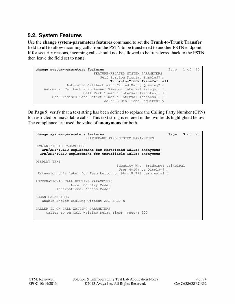
5.2. System Features
Use the change system-parameters features command to set the Trunk-to-Trunk Transfer
field to all to allow incoming calls from the PSTN to be transferred to another PSTN endpoint.
If for security reasons, incoming calls should not be allowed to be transferred back to the PSTN
then leave the field set to none.
On Page 9, verify that a text string has been defined to replace the Calling Party Number (CPN)
for restricted or unavailable calls. This text string is entered in the two fields highlighted below.
The compliance test used the value of anonymous for both.
change system-parameters features Page 1 of 20
FEATURE-RELATED SYSTEM PARAMETERS
Self Station Display Enabled? n
Trunk-to-Trunk Transfer: all
Automatic Callback with Called Party Queuing? n
Automatic Callback - No Answer Timeout Interval (rings): 3
Call Park Timeout Interval (minutes): 10
Off-Premises Tone Detect Timeout Interval (seconds): 20
AAR/ARS Dial Tone Required? y
change system-parameters features Page 9 of 20
FEATURE-RELATED SYSTEM PARAMETERS
CPN/ANI/ICLID PARAMETERS
CPN/ANI/ICLID Replacement for Restricted Calls: anonymous
CPN/ANI/ICLID Replacement for Unavailable Calls: anonymous
DISPLAY TEXT
Identity When Bridging: principal
User Guidance Display? n
Extension only label for Team button on 96xx H.323 terminals? n
INTERNATIONAL CALL ROUTING PARAMETERS
Local Country Code:
International Access Code:
SCCAN PARAMETERS
Enable Enbloc Dialing without ARS FAC? n
CALLER ID ON CALL WAITING PARAMETERS
Caller ID on Call Waiting Delay Timer (msec): 200

CTM; Reviewed:
SPOC 10/14/2013
Solution & Interoperability Test Lab Application Notes
©2013 Avaya Inc. All Rights Reserved.
10 of 74
CoxC63S63SBCE62
5.3. IP Node Names
Use the change node-names ip command to verify that node names have been previously
defined for the IP addresses of the server running Communication Manager (procr) and for
Session Manager (sessionMgr). These node names will be needed for defining the service
provider signaling group in Section 5.6.
5.4. Codecs
Use the change ip-codec-set command to define a list of codecs to use for calls between the
enterprise and the service provider. The list should include the codecs and preferred order
defined by the service provider. For the compliance test, codec G.711MU was tested using ip-
codec-set 3. To configure the codecs, enter the codecs in the Audio Codec column of the table
in the order of preference. Default values can be used for all other fields.
On Page 2, set the Fax Mode to off since T.38 fax calls are not supported with this solution.
change ip-codec-set 3 Page 1 of 2
IP Codec Set
Codec Set: 3
Audio Silence Frames Packet
Codec Suppression Per Pkt Size(ms)
1: G.711MU n 2 20
2:
3:
change node-names ip Page 1 of 2
IP NODE NAMES
Name IP Address
cmm 10.32.128.4
default 0.0.0.0
procr 10.32.128.4
procr6 ::
sessionMgr 10.32.24.235
change ip-codec-set 3 Page 2 of 2
IP Codec Set
Allow Direct-IP Multimedia? n
Mode Redundancy
FAX off 0
Modem off 0
TDD/TTY US 3

CTM; Reviewed:
SPOC 10/14/2013
Solution & Interoperability Test Lab Application Notes
©2013 Avaya Inc. All Rights Reserved.
11 of 74
CoxC63S63SBCE62
5.5. IP Network Region
Create a separate IP network region for the service provider trunk. This allows for separate
codec or quality of service settings to be used (if necessary) for calls between the enterprise and
the service provider versus calls within the enterprise or elsewhere. For the compliance test, IP
network region 3 was chosen for the service provider trunk. Use the change ip-network-region
3 command to configure region 3 with the following parameters:
• Set the Authoritative Domain field to match the SIP domain of the enterprise. In this
configuration, the domain name is avaya.com. This name appears in the “From” header
of SIP messages originating from this IP region.
• Enter a descriptive name in the Name field.
• Enable IP-IP Direct Audio (shuffling) to allow audio traffic to be sent directly between
IP endpoints without using media resources in the Avaya Media Gateway. Set both
Intra-region and Inter-region IP-IP Direct Audio to yes. This is the default setting.
Shuffling can be further restricted at the trunk level on the Signaling Group form.
• Set the Codec Set field to the IP codec set defined in Section 5.4.
• Default values can be used for all other fields.
change ip-network-region 3 Page 1 of 20
IP NETWORK REGION
Region: 3
Location: Authoritative Domain: avaya.com
Name: SP Region Stub Network Region: n MEDIA PARAMETERS Intra-region IP-IP Direct Audio: yes
Codec Set: 3 Inter-region IP-IP Direct Audio: yes
UDP Port Min: 2048 IP Audio Hairpinning? n
UDP Port Max: 3329
DIFFSERV/TOS PARAMETERS
Call Control PHB Value: 46
Audio PHB Value: 46
Video PHB Value: 26
802.1P/Q PARAMETERS
Call Control 802.1p Priority: 6
Audio 802.1p Priority: 6
Video 802.1p Priority: 5 AUDIO RESOURCE RESERVATION PARAMETERS
H.323 IP ENDPOINTS RSVP Enabled? n
H.323 Link Bounce Recovery? y
Idle Traffic Interval (sec): 20
Keep-Alive Interval (sec): 5
Keep-Alive Count: 5

CTM; Reviewed:
SPOC 10/14/2013
Solution & Interoperability Test Lab Application Notes
©2013 Avaya Inc. All Rights Reserved.
12 of 74
CoxC63S63SBCE62
On Page 4, define the IP codec set to be used for traffic between region 3 and region 1. Enter the
desired IP codec set in the codec set column of the row with destination region (dst rgn) 1.
Default values may be used for all other fields. The example below shows the settings used for
the compliance test. It indicates that codec set 3 will be used for calls between region 3 (the
service provider region) and region 1 (the rest of the enterprise). Creating this table entry for IP
network region 3 will automatically create a complementary table entry on the IP network region
1 form for destination region 3. This complementary table entry can be viewed using the display
ip-network-region 1 command and navigating to Page 4 (not shown).
5.6. Signaling Group
Use the add signaling-group command to create a signaling group between Communication
Manager and Session Manager for use by the service provider trunk. This signaling group is
used for inbound and outbound calls between the service provider and the enterprise. For the
compliance test, signaling group 3 was used for this purpose and was configured using the
parameters highlighted below.
• Set the Group Type field to sip.
• Set the Transport Method to the recommended default value of tls (Transport Layer
Security). For ease of troubleshooting during testing, the compliance test was conducted
with the Transport Method set to tcp. The transport method specified here is used
between Communication Manager and Session Manager. If TLS is used here, it must also
be used on the Session Manager entity link defined in Section 6.6.
• Set the IMS Enabled field to n. This specifies Communication Manager will serve as an
Evolution Server for Session Manager.
• Set the Peer Detection Enabled field to y. The Peer-Server field will initially be set to
Others and cannot be changed via administration. Later, the Peer-Server field will
automatically change to SM once Communication Manager detects its peer as a Session
Manager.
• Set the Near-end Node Name to procr. This node name maps to the IP address of the
Communication Manager as defined in Section 5.3.
• Set the Far-end Node Name to sessionMgr. This node name maps to the IP address of
Session Manager as defined in Section 5.3.
• Set the Near-end Listen Port and Far-end Listen Port to a valid unused port instead of
the default well-known port value. (For TLS, the well-known port value is 5061 and for
TCP the well-known port value is 5060). At the time of Session Manager installation, a
SIP connection between Communication Manager and Session Manager would have been
established for use by all Communication Manager SIP traffic using the well-known port
change ip-network-region 3 Page 4 of 20
Source Region: 3 Inter Network Region Connection Management I M
G A t
dst codec direct WAN-BW-limits Video Intervening Dyn A G c rgn set WAN Units Total Norm Prio Shr Regions CAC R L e
1 3 y NoLimit n t
2
3 3 all

CTM; Reviewed:
SPOC 10/14/2013
Solution & Interoperability Test Lab Application Notes
©2013 Avaya Inc. All Rights Reserved.
13 of 74
CoxC63S63SBCE62
value for TLS or TCP. By creating a new signaling group with a separate port value, a
separate SIP connection is created between Communication Manager and Session
Manager for SIP traffic to and from the service provider. As a result, any signaling group
or trunk group settings (Section 5.7) will only affect the service provider traffic and not
other SIP traffic at the enterprise. The compliance test was conducted with the Near-end
Listen Port and Far-end Listen Port set to 5062.
• Set the Far-end Network Region to the IP network region defined for the service
provider in Section 5.5.
• Set the Far-end Domain to the domain of the enterprise.
• Set Direct IP-IP Audio Connections to y. This field will enable media shuffling on the
SIP trunk allowing Communication Manager to redirect media traffic directly between
the SIP trunk and the enterprise endpoint.
• Set the DTMF over IP field to rtp-payload. This value enables Communication
Manager to send DTMF transmissions using RFC 2833.
• Set the Alternate Route Timer to 15. This defines the number of seconds that
Communication Manager will wait for a response (other than “100 Trying”) to an
outbound INVITE before selecting another route. If an alternate route is not defined,
then the call is cancelled after this interval.
• Default values may be used for all other fields.
add signaling-group 3 Page 1 of 2
SIGNALING GROUP
Group Number: 3 Group Type: sip
IMS Enabled? n Transport Method: tcp
Q-SIP? n
IP Video? n Enforce SIPS URI for SRTP? y
Peer Detection Enabled? y Peer Server: SM
Prepend '+' to Outgoing Calling/Alerting/Diverting/Connected Public Numbers? y
Remove '+' from Incoming Called/Calling/Alerting/Diverting/Connected Numbers? n
Near-end Node Name: procr Far-end Node Name: sessionMgr
Near-end Listen Port: 5062 Far-end Listen Port: 5062
Far-end Network Region: 3
Far-end Secondary Node Name:
Far-end Domain: avaya.com
Bypass If IP Threshold Exceeded? n
Incoming Dialog Loopbacks: eliminate RFC 3389 Comfort Noise? n
DTMF over IP: rtp-payload Direct IP-IP Audio Connections? y
Session Establishment Timer(min): 3 IP Audio Hairpinning? n
Enable Layer 3 Test? n Initial IP-IP Direct Media? n
H.323 Station Outgoing Direct Media? n Alternate Route Timer(sec): 15

CTM; Reviewed:
SPOC 10/14/2013
Solution & Interoperability Test Lab Application Notes
©2013 Avaya Inc. All Rights Reserved.
14 of 74
CoxC63S63SBCE62
5.7. Trunk Group
Use the add trunk-group command to create a trunk group for the signaling group created in
Section 5.6. For the compliance test, trunk group 3 was configured using the parameters
highlighted below.
• Set the Group Type field to sip.
• Enter a descriptive name for the Group Name.
• Enter an available trunk access code (TAC) that is consistent with the existing dial plan
in the TAC field.
• Set the Service Type field to public-ntwrk.
• Set Member Assignment Method to auto.
• Set the Signaling Group to the signaling group shown in Section 5.6.
• Set the Number of Members field to the number of trunk members in the SIP trunk
group. This value determines how many simultaneous SIP calls can be supported by this
trunk.
• Default values were used for all other fields.
On Page 2, the Redirect On OPTIM Failure value is the amount of time (in milliseconds) that
Communication Manager will wait for a response (other than “100 Trying”) to a pending
INVITE sent to an EC500 remote endpoint before selecting another route. If another route is not
defined, then the call is cancelled after this interval. This time interval should be set to a value
equal to the Alternate Route Timer on the signaling group form described in Section 5.6.
Verify that the Preferred Minimum Session Refresh Interval is set to a value acceptable to the
service provider. This value defines the interval that re-INVITEs must be sent to keep the active
session alive. For the compliance test, the value of 600 seconds was used.
add trunk-group 3 Page 1 of 21
TRUNK GROUP
Group Number: 3 Group Type: sip CDR Reports: y
Group Name: SP Trunk COR: 1 TN: 1 TAC: 1003
Direction: two-way Outgoing Display? n
Dial Access? n Night Service:
Queue Length: 0
Service Type: public-ntwrk Auth Code? n
Member Assignment Method: auto
Signaling Group: 3 Number of Members: 10

CTM; Reviewed:
SPOC 10/14/2013
Solution & Interoperability Test Lab Application Notes
©2013 Avaya Inc. All Rights Reserved.
15 of 74
CoxC63S63SBCE62
On Page 3, set the Numbering Format field to private. This field specifies the format of the
calling party number (CPN) sent to the far-end. Beginning with Communication Manager 6.0,
public numbers are automatically preceded with a + sign (E.164 numbering format) when passed
in the SIP From, Contact and P-Asserted Identity headers. To remove the + sign, the
Numbering Format was set to private and the Numbering Format in the route pattern was set
to unk-unk (see Section 5.9).
Set the Replace Restricted Numbers and Replace Unavailable Numbers fields to y. This will
allow the CPN displayed on local endpoints to be replaced with the value set in Section 5.2, if
the inbound call enabled CPN block. For outbound calls, these same settings request that CPN
block be activated on the far-end destination if a local user requests CPN block on a particular
call routed out this trunk. Default values were used for all other fields.
add trunk-group 3 Page 2 of 21
Group Type: sip
TRUNK PARAMETERS
Unicode Name: auto
Redirect On OPTIM Failure: 15000
SCCAN? n Digital Loss Group: 18
Preferred Minimum Session Refresh Interval(sec): 600
Disconnect Supervision - In? y Out? y
XOIP Treatment: auto Delay Call Setup When Accessed Via IGAR? n
add trunk-group 3 Page 3 of 21
TRUNK FEATURES
ACA Assignment? n Measured: none
Maintenance Tests? y
Numbering Format: private
UUI Treatment: service-provider
Replace Restricted Numbers? y
Replace Unavailable Numbers? y
Modify Tandem Calling Number: no
Show ANSWERED BY on Display? y
DSN Term? n SIP ANAT Supported? N

CTM; Reviewed:
SPOC 10/14/2013
Solution & Interoperability Test Lab Application Notes
©2013 Avaya Inc. All Rights Reserved.
16 of 74
CoxC63S63SBCE62
On Page 4, set the Mark Users as Phone field to y which is required by Cox Communications.
Since Cox Communications does not support all REFER scenarios (e.g., REFER with replaces)
then the Network Call Redirection field must be set to n. Set the Send Diversion Header field
to y and the Support Request History field to n. The Send Diversion Header field provides
additional information to the network if the call has been redirected. These settings are needed
to support call forwarding of inbound calls back to the PSTN and some Extension to Cellular
(EC500) call scenarios.
Set the Telephone Event Payload Type to 101, the value used by Cox Communications.
To ensure interoperability with Avaya SIP endpoints, the Mark Users as Phone field must also
be set to y on the SIP trunk used by the SIP endpoints to register and communicate with the
Session Manager. In most cases, this will be the trunk created during the initial installation of the
Session Manager. In the case of the compliance test, this was trunk-group 1.
change trunk-group 1 Page 4 of 21
PROTOCOL VARIATIONS
Mark Users as Phone? y
Prepend '+' to Calling/Alerting/Diverting/Connected Number? n
Send Transferring Party Information? n
Network Call Redirection? n
Send Diversion Header? n
Support Request History? y
Telephone Event Payload Type:
Shuffling with SDP? n
Convert 180 to 183 for Early Media? n
Always Use re-INVITE for Display Updates? n
Identity for Calling Party Display: P-Asserted-Identity
Block Sending Calling Party Location in INVITE? n
Accept Redirect to Blank User Destination? n
Enable Q-SIP? n
add trunk-group 3 Page 4 of 21
PROTOCOL VARIATIONS
Mark Users as Phone? y
Prepend '+' to Calling/Alerting/Diverting/Connected Number? n
Send Transferring Party Information? n
Network Call Redirection? n
Send Diversion Header? y
Support Request History? n
Telephone Event Payload Type: 101
Shuffling with SDP? n
Convert 180 to 183 for Early Media? n
Always Use re-INVITE for Display Updates? n
Identity for Calling Party Display: P-Asserted-Identity
Block Sending Calling Party Location in INVITE? n
Accept Redirect to Blank User Destination? n
Enable Q-SIP? n

CTM; Reviewed:
SPOC 10/14/2013
Solution & Interoperability Test Lab Application Notes
©2013 Avaya Inc. All Rights Reserved.
17 of 74
CoxC63S63SBCE62
5.8. Calling Party Information
The calling party number is sent in the SIP “From”, “Contact” and “PAI” headers. Since private
numbering was selected to define the format of this number (Section 5.7), use the change
private-numbering command to create an entry for each extension which has a DID assigned.
The DID number will be assigned by the SIP service provider. It is used to authenticate the
caller.
In the sample configuration, five DID numbers were assigned for testing. These five numbers
were assigned to the five extensions 40003, 40006, 40022, 40023 and 40024. Thus, these same
10-digit numbers were used in the outbound calling party information on the service provider
trunk when calls were originated from these extensions.
In a real customer environment, normally the DID number is comprised of the local extension
plus a prefix. If this is true, then a single private numbering entry can be applied for all
extensions. In the example below, all stations with a 5-digit extension beginning with 4 will send
the calling party number as the Private Prefix plus the extension number.
change private-numbering 5 Page 1 of 2
NUMBERING - PRIVATE FORMAT
Ext Ext Trk Private Total
Len Code Grp(s) Prefix Len
5 4 5 Total Administered: 2
5 4 3 70355 10 Maximum Entries: 540
change private-numbering 5 Page 1 of 2
NUMBERING - PRIVATE FORMAT
Ext Ext Trk Private Total
Len Code Grp(s) Prefix Len
5 4 5 Total Administered: 6
5 40003 3 7035551234 10 Maximum Entries: 540
5 40006 3 7035551235 10
5 40022 3 7035551236 10 5 40023 3 7035551237 10
5 40024 3 7025551238 10
CTM; Reviewed:
SPOC 10/14/2013
Solution & Interoperability Test Lab Application Notes
©2013 Avaya Inc. All Rights Reserved.
18 of 74
CoxC63S63SBCE62
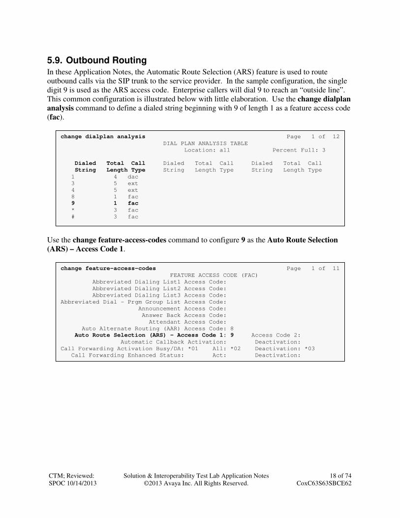
5.9. Outbound Routing
In these Application Notes, the Automatic Route Selection (ARS) feature is used to route
outbound calls via the SIP trunk to the service provider. In the sample configuration, the single
digit 9 is used as the ARS access code. Enterprise callers will dial 9 to reach an “outside line”.
This common configuration is illustrated below with little elaboration. Use the change dialplan
analysis command to define a dialed string beginning with 9 of length 1 as a feature access code
(fac).
Use the change feature-access-codes command to configure 9 as the Auto Route Selection
(ARS) – Access Code 1.
change feature-access-codes Page 1 of 11
FEATURE ACCESS CODE (FAC)
Abbreviated Dialing List1 Access Code:
Abbreviated Dialing List2 Access Code:
Abbreviated Dialing List3 Access Code:
Abbreviated Dial - Prgm Group List Access Code:
Announcement Access Code:
Answer Back Access Code:
Attendant Access Code:
Auto Alternate Routing (AAR) Access Code: 8
Auto Route Selection (ARS) - Access Code 1: 9 Access Code 2:
Automatic Callback Activation: Deactivation:
Call Forwarding Activation Busy/DA: *01 All: *02 Deactivation: *03
Call Forwarding Enhanced Status: Act: Deactivation:
change dialplan analysis Page 1 of 12
DIAL PLAN ANALYSIS TABLE
Location: all Percent Full: 3
Dialed Total Call Dialed Total Call Dialed Total Call
String Length Type String Length Type String Length Type
1 4 dac
3 5 ext
4 5 ext
8 1 fac
9 1 fac
* 3 fac
# 3 fac

CTM; Reviewed:
SPOC 10/14/2013
Solution & Interoperability Test Lab Application Notes
©2013 Avaya Inc. All Rights Reserved.
19 of 74
CoxC63S63SBCE62
Use the change ars analysis command to configure the routing of dialed digits following the
first digit 9. The example below shows a subset of the dialed strings tested as part of the
compliance test. See Section 2.1 for the complete list of call types tested. All dialed strings are
mapped to route pattern 2 which contains the SIP trunk to the service provider (as defined next).
change ars analysis 0 Page 1 of 2
ARS DIGIT ANALYSIS TABLE
Location: all Percent Full: 1
Dialed Total Route Call Node ANI String Min Max Pattern Type Num Reqd
0 1 1 2 op n
0 11 11 2 op n
011 10 18 2 intl n
1703 11 11 2 fnpa n
1732 11 11 2 fnpa n
1800 11 11 2 fnpa n
1877 11 11 2 fnpa n
1908 11 11 2 fnpa n
411 3 3 2 svcl n

CTM; Reviewed:
SPOC 10/14/2013
Solution & Interoperability Test Lab Application Notes
©2013 Avaya Inc. All Rights Reserved.
20 of 74
CoxC63S63SBCE62
The route pattern defines which trunk group will be used for the call and performs any necessary
digit manipulation. Use the change route-pattern command to configure the parameters for the
service provider route pattern in the following manner. The example below shows the values
used for route pattern 2 during the compliance test.
• Pattern Name: Enter a descriptive name.
• Grp No: Enter the outbound trunk group for the SIP service provider. For the compliance
test, trunk group 3 was used.
• FRL: Set the Facility Restriction Level (FRL) field to a level that allows access to this
trunk for all users that require it. The value of 0 is the least restrictive level.
• Pfx Mrk: 1 The prefix mark (Pfx Mrk) of one will prefix any FNPA 10-digit number
with a 1 and leave numbers of any other length unchanged. This will ensure 1 + 10 digits
are sent to the Session Manager for long distance North American Numbering Plan
(NANP) numbers.
• Numbering Format: unk-unk All calls using this route pattern will use the private
numbering table. See setting of the Numbering Format in the trunk group form for full
details in Section 5.7.
• LAR: next
change route-pattern 2 Page 1 of 3
Pattern Number: 4 Pattern Name: SP Route
SCCAN? n Secure SIP? n
Grp FRL NPA Pfx Hop Toll No. Inserted DCS/ IXC
No Mrk Lmt List Del Digits QSIG
Dgts Intw
1: 3 0 1 n user
2: n user
3: n user
4: n user
5: n user
6: n user
BCC VALUE TSC CA-TSC ITC BCIE Service/Feature PARM No. Numbering LAR
0 1 2 M 4 W Request Dgts Format
Subaddress
1: y y y y y n n rest unk-unk next
2: y y y y y n n rest none
3: y y y y y n n rest none
4: y y y y y n n rest none
5: y y y y y n n rest none
6: y y y y y n n rest none

CTM; Reviewed:
SPOC 10/14/2013
Solution & Interoperability Test Lab Application Notes
©2013 Avaya Inc. All Rights Reserved.
21 of 74
CoxC63S63SBCE62
6. Configure Avaya Aura® Session Manager This section provides the procedures for configuring Session Manager. The procedures include
configuring the following items:
• SIP domain
• Logical/physical Location that can be occupied by SIP Entities
• Adaptation module to perform dial plan manipulation
• SIP Entities corresponding to Communication Manager, the Avaya SBCE and Session
Manager
• Entity Links, which define the SIP trunk parameters used by Session Manager when routing
calls to/from SIP Entities
• Routing Policies, which control call routing between the SIP Entities
• Dial Patterns, which governs which Routing Policy is used to service a call.
• Session Manager, corresponding to the Session Manager Server to be managed by System
Manager.
It may not be necessary to create all the items above when creating a connection to the service
provider since some of these items would have already been defined as part of the initial Session
Manager installation. This includes items such as certain SIP domains, locations, SIP entities,
and Session Manager itself. However, each item should be reviewed to verify the configuration.

CTM; Reviewed:
SPOC 10/14/2013
Solution & Interoperability Test Lab Application Notes
©2013 Avaya Inc. All Rights Reserved.
22 of 74
CoxC63S63SBCE62
6.1. Avaya Aura® System Manager Login and Navigation
Session Manager configuration is accomplished by accessing the browser-based GUI of System
Manager, using the URL https://<ip-address>/SMGR, where <ip-address> is the IP address of
System Manager. Log in with the appropriate credentials and click on Login (not shown). The
Home page is displayed. The links displayed below will be referenced in subsequent sections to
navigate to items requiring configuration. Most items will be located under the Elements �
Routing link highlighted below.
CTM; Reviewed:
SPOC 10/14/2013
Solution & Interoperability Test Lab Application Notes
©2013 Avaya Inc. All Rights Reserved.
23 of 74
CoxC63S63SBCE62
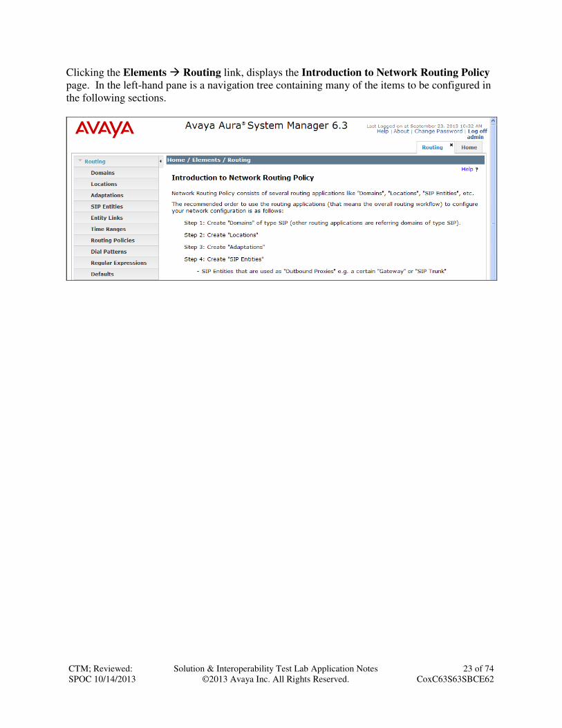
Clicking the Elements � Routing link, displays the Introduction to Network Routing Policy
page. In the left-hand pane is a navigation tree containing many of the items to be configured in
the following sections.

CTM; Reviewed:
SPOC 10/14/2013
Solution & Interoperability Test Lab Application Notes
©2013 Avaya Inc. All Rights Reserved.
24 of 74
CoxC63S63SBCE62
6.2. Specify SIP Domain
Create a SIP domain for each domain of which Session Manager will need to be aware in order
to route calls. For the compliance test, this includes the enterprise domain (avaya.com).
Navigate to Routing � Domains in the left-hand navigation pane (Section 6.1) and click the
New button in the right pane (not shown). In the new right pane that appears (shown below), fill
in the following:
• Name: Enter the domain name.
• Type: Select sip from the pull-down menu.
• Notes: Add a brief description (optional).
Click Commit. The screen below shows the entry for the enterprise domain.

CTM; Reviewed:
SPOC 10/14/2013
Solution & Interoperability Test Lab Application Notes
©2013 Avaya Inc. All Rights Reserved.
25 of 74
CoxC63S63SBCE62
6.3. Add Location
Locations can be used to identify logical and/or physical locations where SIP Entities reside for
purposes of bandwidth management and call admission control. A single location was defined
for the enterprise even though multiple subnets were used. The screens below show the addition
of the location named Location 1, which includes all equipment on the enterprise including
Communication Manager, Session Manager and the Avaya SBCE.
To add a location, navigate to Routing � Locations in the left-hand navigation pane (Section
6.1) and click the New button in the right pane (not shown). In the new right pane that appears
(shown below), fill in the following:
In the General section, enter the following values. Use default values for all remaining fields.
• Name: Enter a descriptive name for the location.
• Notes: Add a brief description (optional).
Scroll down to the Location Pattern section. Click Add and enter the following values. Use
default values for all remaining fields.
• IP Address Pattern: Add all IP address patterns used to identify the location. The
compliance test used the two subnets highlighted below.
• Notes: Add a brief description (optional).
Click Commit to save.

CTM; Reviewed:
SPOC 10/14/2013
Solution & Interoperability Test Lab Application Notes
©2013 Avaya Inc. All Rights Reserved.
26 of 74
CoxC63S63SBCE62
6.4. Add Adaptation Module
Session Manager can be configured with adaptation modules that can modify SIP messages
before or after routing decisions have been made. A generic adaptation module
DigitConversionAdapter supports digit conversion of telephone numbers in specific headers of
SIP messages. Other adaptation modules are built on this generic, and can modify other headers
to permit interoperability with third party SIP products.
For the compliance test, one adaptation was created for Communication Manager. The
adaptation mapped inbound DID numbers from Cox Communications to local Communication
Manager extensions.
To create the adaptation that will be applied to the Communication Manager SIP entity, navigate
to Routing � Adaptations in the left-hand navigation pane (Section 6.1) and click on the New
button in the right pane (not shown). In the new right pane that appears (shown below), fill in
the following:
In the General section, enter the following values. Use default values for all remaining fields.
• Adaptation name: Enter a descriptive name for the adaptation.
• Module name: Enter DigitConversionAdapter.
• Notes: Enter a description (optional).

CTM; Reviewed:
SPOC 10/14/2013
Solution & Interoperability Test Lab Application Notes
©2013 Avaya Inc. All Rights Reserved.
27 of 74
CoxC63S63SBCE62
To map inbound DID numbers from Cox Communications to Communication Manager
extensions, scroll down to the Digit Conversion for Outgoing Calls from SM section. Create
an entry for each DID to be mapped. Click Add and enter the following values for each
mapping. Use default values for all remaining fields.
• Matching Pattern: Enter a digit string used to match the inbound DID number.
• Min: Enter a minimum dialed number length used in the match criteria.
• Max: Enter a maximum dialed number length used in the match criteria.
• Delete Digits Enter the number of digits to delete from the beginning of the
received number.
• Insert Digits: Enter the number of digits to insert at the beginning of the received
number.
• Address to modify: Select destination since this digit conversion only applies to the
destination number.
Click Commit to save.
In a real customer environment, often the DID number is comprised of the local extension plus a
prefix. If this is true, then a single digit conversion entry can be created for all extensions. In the
example below, a 5 digit prefix is deleted from each incoming DID number leaving a 5 digit
extension to be routed by Session Manager.
CTM; Reviewed:
SPOC 10/14/2013
Solution & Interoperability Test Lab Application Notes
©2013 Avaya Inc. All Rights Reserved.
28 of 74
CoxC63S63SBCE62
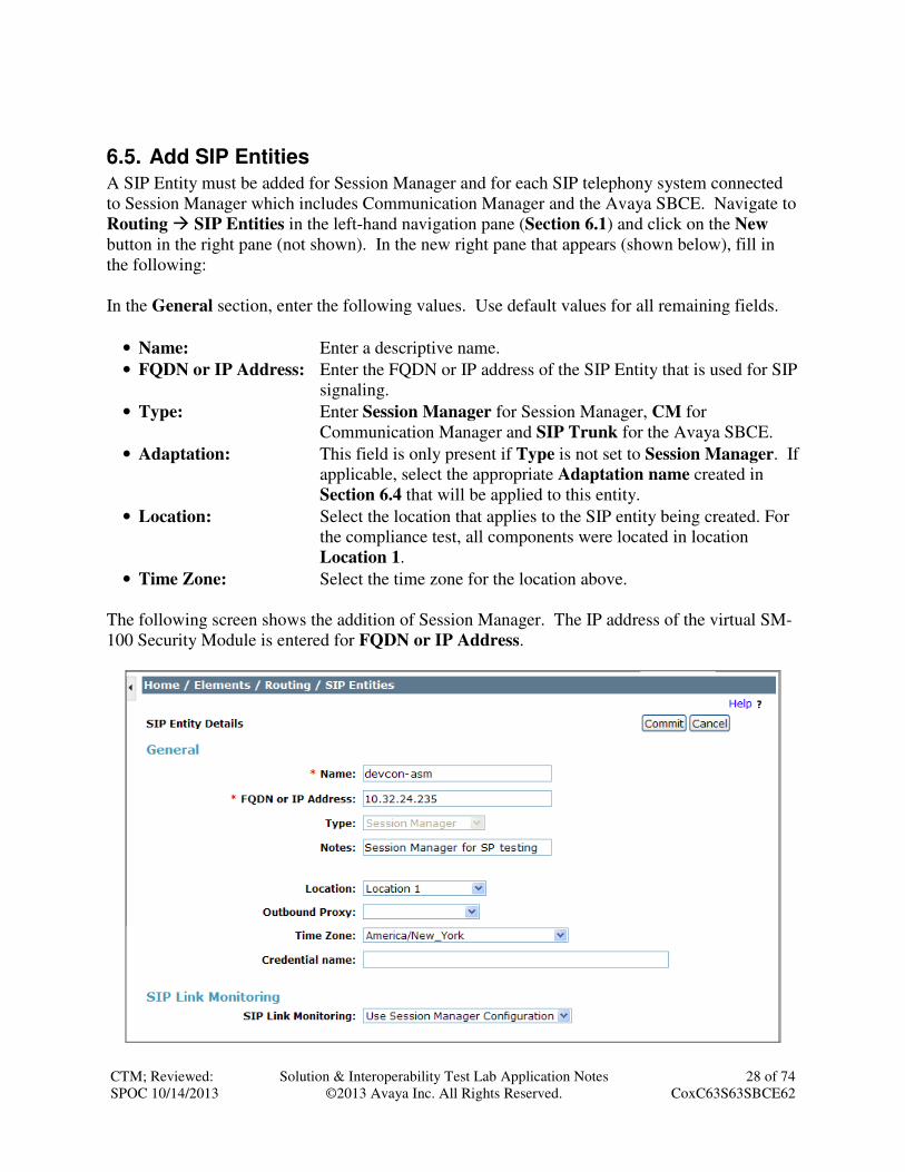
6.5. Add SIP Entities
A SIP Entity must be added for Session Manager and for each SIP telephony system connected
to Session Manager which includes Communication Manager and the Avaya SBCE. Navigate to
Routing � SIP Entities in the left-hand navigation pane (Section 6.1) and click on the New
button in the right pane (not shown). In the new right pane that appears (shown below), fill in
the following:
In the General section, enter the following values. Use default values for all remaining fields.
• Name: Enter a descriptive name.
• FQDN or IP Address: Enter the FQDN or IP address of the SIP Entity that is used for SIP
signaling.
• Type: Enter Session Manager for Session Manager, CM for
Communication Manager and SIP Trunk for the Avaya SBCE.
• Adaptation: This field is only present if Type is not set to Session Manager. If
applicable, select the appropriate Adaptation name created in
Section 6.4 that will be applied to this entity.
• Location: Select the location that applies to the SIP entity being created. For
the compliance test, all components were located in location
Location 1.
• Time Zone: Select the time zone for the location above.
The following screen shows the addition of Session Manager. The IP address of the virtual SM-
100 Security Module is entered for FQDN or IP Address.

CTM; Reviewed:
SPOC 10/14/2013
Solution & Interoperability Test Lab Application Notes
©2013 Avaya Inc. All Rights Reserved.
29 of 74
CoxC63S63SBCE62
To define the ports used by Session Manager, scroll down to the Port section of the SIP Entity
Details screen. This section is only present for Session Manager SIP entities.
In the Port section, click Add and enter the following values. Use default values for all
remaining fields:
• Port: Port number on which the Session Manager can listen for SIP
requests.
• Protocol: Transport protocol to be used with this port.
• Default Domain: The default domain associated with this port. For the compliance
test, this was the enterprise SIP domain.
Defaults can be used for the remaining fields. Click Commit to save.
For the compliance test, four port entries were used. The first three are the standard ports used
for SIP traffic: port 5060 for UDP/TCP and port 5061 for TLS. In addition, port 5062 defined in
Section 5.6 for use with service provider SIP traffic between Communication Manager and
Session Manager was added to the list.

CTM; Reviewed:
SPOC 10/14/2013
Solution & Interoperability Test Lab Application Notes
©2013 Avaya Inc. All Rights Reserved.
30 of 74
CoxC63S63SBCE62
The following screen shows the addition of Communication Manager. In order for Session
Manager to send SIP service provider traffic on a separate entity link to Communication
Manager, this requires the creation of a separate SIP entity for Communication Manager other
than the one created at Session Manager installation for use with all other SIP traffic. The FQDN
or IP Address field is set to the IP address of Communication Manager. For the Adaptation
field, select the adaptation module previously defined for dial plan digit manipulation in Section
6.4. The Location field is set to Location 1 which is the location defined for the subnet where
Communication Manager resides.

CTM; Reviewed:
SPOC 10/14/2013
Solution & Interoperability Test Lab Application Notes
©2013 Avaya Inc. All Rights Reserved.
31 of 74
CoxC63S63SBCE62
The following screen shows the addition of the Avaya SBCE. The FQDN or IP Address field is
set to the IP address of its private network interface (see Figure 1). The Location field is set to
Location 1 which is the location defined for the subnet where the Avaya SBCE resides.

CTM; Reviewed:
SPOC 10/14/2013
Solution & Interoperability Test Lab Application Notes
©2013 Avaya Inc. All Rights Reserved.
32 of 74
CoxC63S63SBCE62
6.6. Add Entity Links
A SIP trunk between Session Manager and a telephony system is described by an Entity Link.
Two Entity Links were created: one to Communication Manager for use only by service provider
traffic and one to the Avaya SBCE. To add an Entity Link, navigate to Routing � Entity Links
in the left-hand navigation pane (Section 6.1) and click on the New button in the right pane (not
shown). In the new right pane that appears (shown below), fill in the following:
• Name: Enter a descriptive name.
• SIP Entity 1: Select the Session Manager.
• Protocol: Select the transport protocol used for this link. This must match the
protocol used in the Communication Manager signaling group in
Section 5.6.
• Port: Port number on which Session Manager will receive SIP requests
from the far-end. For the Communication Manager Entity Link,
this must match the Far-end Listen Port defined on the
Communication Manager signaling group in Section 5.6.
• SIP Entity 2: Select the name of the other system. For the Communication
Manager Entity Link, select the Communication Manager SIP
Entity defined in Section 6.5.
• Port: Port number on which the other system receives SIP requests from
the Session Manager. For the Communication Manager Entity
Link, this must match the Near-end Listen Port defined on the
Communication Manager signaling group in Section 5.6.
• Connection Policy: Select Trusted from pull-down menu.
Click Commit to save.
The following screen illustrates the Entity Link to Communication Manager. The protocol and
ports defined here must match the values used on the Communication Manager signaling group
form in Section 5.6. For the compliance test, the TCP protocol was used but the recommended
configuration is to use TLS.

CTM; Reviewed:
SPOC 10/14/2013
Solution & Interoperability Test Lab Application Notes
©2013 Avaya Inc. All Rights Reserved.
33 of 74
CoxC63S63SBCE62
The following screen illustrates the Entity Link to the Avaya SBCE.

CTM; Reviewed:
SPOC 10/14/2013
Solution & Interoperability Test Lab Application Notes
©2013 Avaya Inc. All Rights Reserved.
34 of 74
CoxC63S63SBCE62
6.7. Add Routing Policies
Routing policies describe the conditions under which calls will be routed to the SIP Entities
specified in Section 6.5. Two routing policies must be added: one for Communication Manager
and one for the Avaya SBCE. To add a routing policy, navigate to Routing � Routing Policies
in the left-hand navigation pane (Section 6.1) and click on the New button in the right pane (not
shown). In the new right pane that appears (shown below), fill in the following:
In the General section, enter the following values. Use default values for all remaining fields.
• Name: Enter a descriptive name.
• Notes: Add a brief description (optional).
In the SIP Entity as Destination section, click Select. The SIP Entity List page opens (not
shown). Select the appropriate SIP entity to which this routing policy applies and click Select.
The selected SIP Entity displays on the Routing Policy Details page as shown below. Use
default values for remaining fields. Click Commit to save.
The following screens show the Routing Policies for Communication Manager and the Avaya
SBCE.

CTM; Reviewed:
SPOC 10/14/2013
Solution & Interoperability Test Lab Application Notes
©2013 Avaya Inc. All Rights Reserved.
35 of 74
CoxC63S63SBCE62

CTM; Reviewed:
SPOC 10/14/2013
Solution & Interoperability Test Lab Application Notes
©2013 Avaya Inc. All Rights Reserved.
36 of 74
CoxC63S63SBCE62
6.8. Add Dial Patterns
Dial Patterns are needed to route calls through Session Manager. For the compliance test, dial
patterns were needed to route calls from Communication Manager to Cox Communications and
vice versa. Dial Patterns define which route policy will be selected for a particular call based on
the dialed digits, destination domain and originating location. To add a dial pattern, navigate to
Routing � Dial Patterns in the left-hand navigation pane (Section 6.1) and click on the New
button in the right pane (not shown). In the new right pane that appears (shown below), fill in
the following:
In the General section, enter the following values. Use default values for all remaining fields.
• Pattern: Enter a dial string that will be matched against the Request-URI of the
call.
• Min: Enter a minimum length used in the match criteria.
• Max: Enter a maximum length used in the match criteria.
• SIP Domain: Enter the destination domain used in the match criteria.
• Notes: Add a brief description (optional).
In the Originating Locations and Routing Policies section, click Add. From the Originating
Locations and Routing Policy List that appears (not shown), select the appropriate originating
location for use in the match criteria. Lastly, select the routing policy from the list that will be
used to route all calls that match the specified criteria. Click Select.
Default values can be used for the remaining fields. Click Commit to save.

CTM; Reviewed:
SPOC 10/14/2013
Solution & Interoperability Test Lab Application Notes
©2013 Avaya Inc. All Rights Reserved.
37 of 74
CoxC63S63SBCE62
Two examples of the dial patterns used for the compliance test are shown below. The first
example shows that numbers that begin with 1 and have a destination domain of avaya.com from ALL locations use route policy ASBCE-route.

CTM; Reviewed:
SPOC 10/14/2013
Solution & Interoperability Test Lab Application Notes
©2013 Avaya Inc. All Rights Reserved.
38 of 74
CoxC63S63SBCE62
The second example shows that 10 digit numbers that start with 703555 to domain avaya.com
and originating from ALL locations use route policy sp3-cm Route 2. These are the DID
numbers assigned to the enterprise from Cox Communications. All other dial patterns used as
part of the compliance test were configured in a similar manner.

CTM; Reviewed:
SPOC 10/14/2013
Solution & Interoperability Test Lab Application Notes
©2013 Avaya Inc. All Rights Reserved.
39 of 74
CoxC63S63SBCE62
6.9. Add/View Session Manager
The creation of a Session Manager element provides the linkage between System Manager and
Session Manager. This was most likely done as part of the initial Session Manager installation.
To add a Session Manager, from the Home page, navigate to Elements � Session Manager �
Session Manager Administration in the left-hand navigation pane (Section 6.1) and click on
the New button in the right pane (not shown). If the Session Manager already exists, select the
appropriate Session Manager and click View (not shown) to view the configuration. Enter/verify
the data as described below and shown in the following screen:
In the General section, enter the following values:
• SIP Entity Name: Select the SIP Entity created for Session
Manager.
• Description: Add a brief description (optional).
• Management Access Point Host Name/IP: Enter the host name or IP address of the
Session Manager.
The screen below shows the Session Manager values used for the compliance test.

CTM; Reviewed:
SPOC 10/14/2013
Solution & Interoperability Test Lab Application Notes
©2013 Avaya Inc. All Rights Reserved.
40 of 74
CoxC63S63SBCE62
In the Security Module section, enter the following values:
• SIP Entity IP Address: Should be filled in automatically based on the SIP Entity
Name. Otherwise, enter IP address of Session Manager
signaling interface.
• Network Mask: Enter the network mask corresponding to the IP address of
Session Manager.
• Default Gateway: Enter the IP address of the default gateway for Session
Manager.
Use default values for the remaining fields. Click Save (not shown) to add this Session
Manager. The screen below shows the remaining Session Manager values used for the
compliance test.

CTM; Reviewed:
SPOC 10/14/2013
Solution & Interoperability Test Lab Application Notes
©2013 Avaya Inc. All Rights Reserved.
41 of 74
CoxC63S63SBCE62
7. Configure Avaya Session Border Controller for Enterprise This section describes the configuration of the Avaya SBCE. It is assumed that the initial
installation of the Avaya SBCE has been completed including the assignment of a management
IP address. The management interface must be provisioned on a different subnet than either the
Avaya SBCE private or public network interfaces (e.g., A1 and B1). If the management
interface has not been configured on a separate subnet, then contact your Avaya representative
for guidance in correcting the configuration.
On all screens described in this section, it is to be assumed that parameters are left at their default
values unless specified otherwise.
7.1. Access the Management Interface
Use a web browser to access the web interface by entering the URL https://<ip-addr>, where
<ip-addr> is the management IP address assigned during installation. The Avaya SBCE login
page will appear as shown below. Log in with appropriate credentials.

CTM; Reviewed:
SPOC 10/14/2013
Solution & Interoperability Test Lab Application Notes
©2013 Avaya Inc. All Rights Reserved.
42 of 74
CoxC63S63SBCE62
After logging in, the Dashboard screen will appear as shown below. All configuration screens of
the Avaya SBCE are accessed by navigating the menu tree in the left pane.

CTM; Reviewed:
SPOC 10/14/2013
Solution & Interoperability Test Lab Application Notes
©2013 Avaya Inc. All Rights Reserved.
43 of 74
CoxC63S63SBCE62
7.2. Verify Network Configuration and Enable Interfaces
To view the network information provided during installation, navigate to System Management.
In the right pane, click View highlighted below.
A System Information page will appear showing the information provided during installation. In
the Appliance Name field is the name of the device (sp-ucsec1). This name will be referenced
in other configuration screens. The two Network Configuration entries highlighted below are
the only two IP addresses that are directly related to the SIP trunking solution described in these
Application Notes. Interfaces A1 and B1 represent the private and public interfaces of the Avaya
SBCE. Each of these interfaces must be enabled after installation.

CTM; Reviewed:
SPOC 10/14/2013
Solution & Interoperability Test Lab Application Notes
©2013 Avaya Inc. All Rights Reserved.
44 of 74
CoxC63S63SBCE62
To enable the interfaces, first navigate to Device Specific Settings ���� Network Management in
the left pane and select the device being managed in the center pane. In the right pane, click on
the Interface Configuration tab. Verify the Administrative Status is Enabled for both the A1
and B1 interfaces. If not, click Toggle to enable the interface.

CTM; Reviewed:
SPOC 10/14/2013
Solution & Interoperability Test Lab Application Notes
©2013 Avaya Inc. All Rights Reserved.
45 of 74
CoxC63S63SBCE62
7.3. Signaling Interface
A signaling interface defines an IP address, protocols and listen ports that the Avaya SBCE can
use for signaling. Create a signaling interface for both the internal and external sides of the
Avaya SBCE.
To create a new interface, navigate to Device Specific Settings ���� Signaling Interface in the
left pane. In the center pane, select the Avaya SBCE device (sp-ucsec1) to be managed. In the
right pane, select Add. A pop-up window (not shown) will appear requesting the name of the
new interface, followed by a series of pop-up windows in which the interface parameters can be
configured. Once complete, the settings are shown in the far right pane.
For the compliance test, signaling interface Int_Sig_Intf was created for the Avaya SBCE
internal interface and signaling interface Ext_Sig_Intf was created for the Avaya SBCE external
interface. Each is highlighted below. When configuring the interfaces, configure the parameters
as follows:
• Set Name to a descriptive name.
• For the internal interface, set the Signaling IP to the IP address associated with the private
interface (A1) defined in Section 7.2. For the external interface, set the Signaling IP to the
IP address associated with the public interface (B1) defined in Section 7.2.
• In the UDP Port, TCP Port and TLS Port fields, enter the port the Avaya SBCE will listen
on for each transport protocol. For the internal interface, the Avaya SBCE was configured
to listen for TCP on port 5060. For the external interface, the Avaya SBCE was configured
to listen for UDP or TCP on port 5060. Since Cox Communications uses UDP on port 5060,
it would have been sufficient to simply configure the Avaya SBCE for UDP.

CTM; Reviewed:
SPOC 10/14/2013
Solution & Interoperability Test Lab Application Notes
©2013 Avaya Inc. All Rights Reserved.
46 of 74
CoxC63S63SBCE62
7.4. Media Interface
A media interface defines an IP address and port range for transmitting media. Create a media
interface for both the internal and external sides of the Avaya SBCE.
To create a new interface, navigate to Device Specific Settings ���� Media Interface in the left
pane. In the center pane, select the Avaya SBCE device (sp-ucsec1) to be managed. In the right
pane, select Add. A pop-up window (not shown) will appear requesting the name of the new
interface, followed by a series of pop-up windows in which the interface parameters can be
configured. Once complete, the settings are shown in the far right pane.
For the compliance test, media interface Int_Media_Intf was created for the Avaya SBCE
internal interface and media interface Ext_Media_Intf was created for the Avaya SBCE external
interface. Each is highlighted below. When configuring the interfaces, configure the parameters
as follows:
• Set Name to a descriptive name.
• For the internal interface, set the Media IP to the IP address associated with the private
interface (A1) defined in Section 7.2. For the external interface, set the Media IP to the IP
address associated with the public interface (B1) defined in Section 7.2.
• Set Port Range to a range of ports acceptable to both the Avaya SBCE and the far-end. For
the compliance test, the default port range was used for both interfaces.

CTM; Reviewed:
SPOC 10/14/2013
Solution & Interoperability Test Lab Application Notes
©2013 Avaya Inc. All Rights Reserved.
47 of 74
CoxC63S63SBCE62
7.5. Server Interworking
A server interworking profile defines a set of parameters that aid in interworking between the
Avaya SBCE and a connected server. Create a server interworking profile for Session Manager
and the service provider SIP server. These profiles will be applied to the appropriate server in
Section 7.7.1 and 7.7.2.
To create a new profile, navigate to Global Profiles ���� Server Interworking in the left pane. In
the center pane, select Add. A pop-up window (not shown) will appear requesting the name of
the new profile, followed by a series of pop-up windows in which the profile parameters can be
configured. Once complete, the settings are shown in the far right pane. Alternatively, a new
profile may be created by selecting an existing profile in the center pane and clicking the Clone
button in the right pane. This will create a copy of the selected profile which can then be edited
as needed. To view the settings of an existing profile, select the profile from the center pane.
The settings will appear in the right pane.
CTM; Reviewed:
SPOC 10/14/2013
Solution & Interoperability Test Lab Application Notes
©2013 Avaya Inc. All Rights Reserved.
48 of 74
CoxC63S63SBCE62
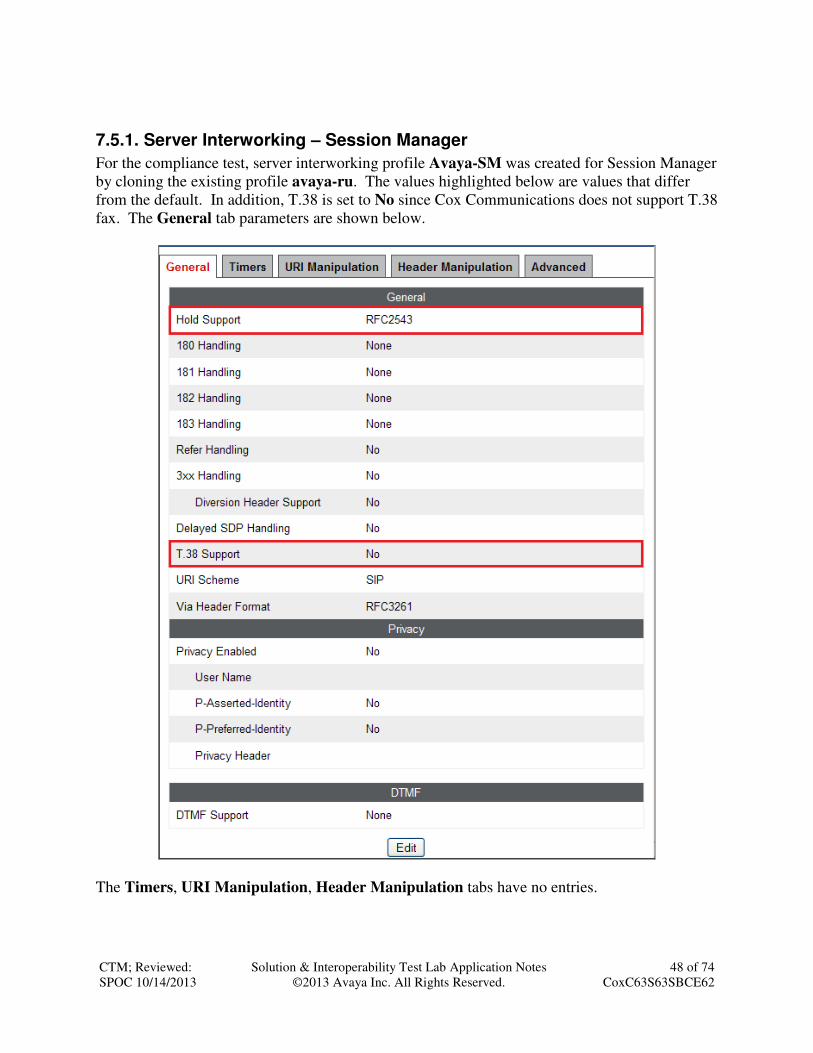
7.5.1. Server Interworking – Session Manager
For the compliance test, server interworking profile Avaya-SM was created for Session Manager
by cloning the existing profile avaya-ru. The values highlighted below are values that differ
from the default. In addition, T.38 is set to No since Cox Communications does not support T.38
fax. The General tab parameters are shown below.
The Timers, URI Manipulation, Header Manipulation tabs have no entries.

CTM; Reviewed:
SPOC 10/14/2013
Solution & Interoperability Test Lab Application Notes
©2013 Avaya Inc. All Rights Reserved.
49 of 74
CoxC63S63SBCE62
The Advanced tab parameters are shown below.

CTM; Reviewed:
SPOC 10/14/2013
Solution & Interoperability Test Lab Application Notes
©2013 Avaya Inc. All Rights Reserved.
50 of 74
CoxC63S63SBCE62
7.5.2. Server Interworking – Cox Communications
For the compliance test, server interworking profile SP-General was created for the Cox
Communications SIP server. When creating the profile, the default values were used for all
parameters including the setting of T.38 Support to No. The General tab parameters are shown
below.
The Timers, URI Manipulation, Header Manipulation tabs have no entries.

CTM; Reviewed:
SPOC 10/14/2013
Solution & Interoperability Test Lab Application Notes
©2013 Avaya Inc. All Rights Reserved.
51 of 74
CoxC63S63SBCE62
The Advanced tab parameters are shown below.
7.6. Signaling Manipulation
Signaling manipulation scripts provides for the manipulation of SIP messages which cannot be
done by other configuration within the Avaya SBCE. It was not necessary to create any
signaling manipulation scripts for interoperability with Cox Communications.

CTM; Reviewed:
SPOC 10/14/2013
Solution & Interoperability Test Lab Application Notes
©2013 Avaya Inc. All Rights Reserved.
52 of 74
CoxC63S63SBCE62
7.7. Server Configuration
A server configuration profile defines the attributes of the physical server. Create a server
configuration profile for Session Manager and the service provider SIP server.
To create a new profile, navigate to Global Profiles ���� Server Configuration in the left pane.
In the center pane, select Add. A pop-up window (not shown) will appear requesting the name
of the new profile, followed by a series of pop-up windows in which the profile parameters can
be configured. Once complete, the settings are shown in the far right pane. To view the settings
of an existing profile, select the profile from the center pane. The settings will appear in the right
pane.

CTM; Reviewed:
SPOC 10/14/2013
Solution & Interoperability Test Lab Application Notes
©2013 Avaya Inc. All Rights Reserved.
53 of 74
CoxC63S63SBCE62
7.7.1. Server Configuration – Session Manager
For the compliance test, server configuration profile Avaya-SM was created for Session
Manager. When creating the profile, configure the General tab parameters as follows:
• Set Server Type to Call Server.
• Set IP Addresses / FQDNs to the IP address of the Session Manager signaling interface.
• Set Supported Transports to the transport protocol used for SIP signaling between Session
Manager and the Avaya SBCE.
• Set the TCP Port to the port Session Manager will listen on for SIP requests from the
Avaya SBCE.
On the Advanced tab, check Enable Grooming and set the Interworking Profile field to the
interworking profile for Session Manager defined in Section 7.5.1.

CTM; Reviewed:
SPOC 10/14/2013
Solution & Interoperability Test Lab Application Notes
©2013 Avaya Inc. All Rights Reserved.
54 of 74
CoxC63S63SBCE62
7.7.2. Server Configuration – Cox Communications
For the compliance test, server configuration profile SP-Cox was created for Cox
Communications. When creating the profile, configure the General tab parameters as follows:
• Set Server Type to Trunk Server.
• Set IP Addresses / FQDNs to the IP address of the Cox Communications SIP server (e.g.,
192.168.222.147 as shown in Figure 1 in Section 3).
• Set Supported Transports to the transport protocol used for SIP signaling between Cox
Communications and the Avaya SBCE. In the compliance test, UDP was tested.
• Set the UDP Port to the standard SIP port of 5060. This is the port Cox Communications
will listen on for SIP requests from the Avaya SBCE.
On the Advanced tab, set the Interworking Profile field to the interworking profile for Cox
Communications defined in Section 7.5.2.

CTM; Reviewed:
SPOC 10/14/2013
Solution & Interoperability Test Lab Application Notes
©2013 Avaya Inc. All Rights Reserved.
55 of 74
CoxC63S63SBCE62
7.8. Application Rules
An application rule defines the allowable SIP applications and associated parameters. An
application rule is one component of the larger endpoint policy group defined in Section 7.11.
For the compliance test, the predefined default-trunk application rule (shown below) was used
for both Session Manager and the Cox Communications SIP server.
To view an existing rule, navigate to Domain Policies ���� Application Rules in the left pane. In
the center pane, select the rule (e.g., default-trunk) to be viewed.

CTM; Reviewed:
SPOC 10/14/2013
Solution & Interoperability Test Lab Application Notes
©2013 Avaya Inc. All Rights Reserved.
56 of 74
CoxC63S63SBCE62
7.9. Media Rules
A media rule defines the processing to be applied to the selected media. A media rule is one
component of the larger endpoint policy group defined in Section 7.11. For the compliance test,
the predefined default-low-med media rule (shown below) was used for both Session Manager
and the Cox Communications SIP server.
To view an existing rule, navigate to Domain Policies ���� Media Rules in the left pane. In the
center pane, select the rule (e.g., default-low-med) to be viewed.
Each of the tabs of the default-low-med media rule containing data is shown below.
The Media NAT tab has no entries.
The Media Encryption tab indicates that no encryption was used.

CTM; Reviewed:
SPOC 10/14/2013
Solution & Interoperability Test Lab Application Notes
©2013 Avaya Inc. All Rights Reserved.
57 of 74
CoxC63S63SBCE62
The Media Anomaly tab shows Media Anomaly Detection was enabled.
The Media Silencing tab has no entries.
The Media QoS settings are shown below.

CTM; Reviewed:
SPOC 10/14/2013
Solution & Interoperability Test Lab Application Notes
©2013 Avaya Inc. All Rights Reserved.
58 of 74
CoxC63S63SBCE62
7.10. Signaling Rules
A signaling rule defines the processing to be applied to the selected signaling traffic. A signaling
rule is one component of the larger endpoint policy group defined in Section 7.11. A specific
signaling rule was created for Session Manager. The Cox Communications SIP server used the
default rule.
To create a new rule, navigate to Domain Policies ���� Signaling Rules in the left pane. In the
center pane, select Add. A pop-up window (not shown) will appear requesting the name of the
new rule, followed by a series of pop-up windows in which the rule parameters can be
configured. Once complete, the settings are shown in the far right pane. To view the settings of
an existing rule, select the rule from the center pane. The settings will appear in the right pane.

CTM; Reviewed:
SPOC 10/14/2013
Solution & Interoperability Test Lab Application Notes
©2013 Avaya Inc. All Rights Reserved.
59 of 74
CoxC63S63SBCE62
7.10.1. Signaling Rules – Session Manager
For the compliance test, signaling rule SessMgr_SigRules was created for Session Manager to
prevent proprietary headers in the SIP messages sent from the Session Manager from being
propagated to Cox Communications. These headers may contain internal addresses or other
information about the internal network. Select this rule in the center pane, then select the
Request Headers tab to view the manipulations performed on request messages such as the
initial INVITE or UPDATE message.
Click Add to create the rule. Keep the default values on all tabs except the Request Headers and
Response Headers tabs. Select the Request Headers tab to create the manipulations performed
on request messages such as the initial INVITE or UPDATE message. An entry is created by
clicking the Add In Header Control or Add Out Header Control button depending on the
direction (relative to the Avaya SBCE) of the message to be modified. Entries were created to
perform the following actions:
1. Removes the AV-Correlation-ID header from INVITE messages in the IN direction
(Session Manager to Avaya SBCE).
2. Removes the Endpoint-View header from ALL messages in the IN direction.

CTM; Reviewed:
SPOC 10/14/2013
Solution & Interoperability Test Lab Application Notes
©2013 Avaya Inc. All Rights Reserved.
60 of 74
CoxC63S63SBCE62
Similarly, manipulations can be performed on SIP response messages. These can be created by
selecting the Response Header tab as shown below. Entries were created in the same manner as
was done on the Request Headers tab. The entries shown perform the following actions:
1. Removes the Endpoint-View header from any 2XX response to ALL messages in the IN
direction (Session Manager to Avaya SBCE).
2. Removes the Endpoint-View header from the 1XX response to an INVITE message in
the IN direction.
7.10.2. Signaling Rules – Cox Communications
The predefined default signaling rule (shown below) was used for the Cox Communications SIP
server. The General tab settings are shown below.

CTM; Reviewed:
SPOC 10/14/2013
Solution & Interoperability Test Lab Application Notes
©2013 Avaya Inc. All Rights Reserved.
61 of 74
CoxC63S63SBCE62
The Requests, Responses, Request Headers, and Response Headers tabs have no entries. The
Signaling QoS tab is shown below.

CTM; Reviewed:
SPOC 10/14/2013
Solution & Interoperability Test Lab Application Notes
©2013 Avaya Inc. All Rights Reserved.
62 of 74
CoxC63S63SBCE62
7.11. Endpoint Policy Groups
An endpoint policy group is a set of policies that will be applied to traffic between the Avaya
SBCE and a signaling endpoint (connected server). Thus, an endpoint policy group must be
created for Session Manager and the service provider SIP server. The endpoint policy group is
applied to the traffic as part of the endpoint flow defined in Section 7.14.
To create a new group, navigate to Domain Policies ���� End Point Policy Groups in the left
pane. In the center pane, select Add. A pop-up window (not shown) will appear requesting the
name of the new group, followed by a series of pop-up windows in which the group parameters
can be configured. Once complete, the settings are shown in the far right pane. To view the
settings of an existing group, select the group from the center pane. The settings will appear in
the right pane.
7.11.1. Endpoint Policy Group – Session Manager
For the compliance test, endpoint policy group TM-Test was created for Session Manager.
Default values were used for each of the rules which comprise the group with the exception of
Application and Signaling. For Application, enter the application rule described in Section
7.8. For Signaling, enter the signaling rule created in Section 7.10.1. The details of the default
settings for Media are showed in Section 7.9.

CTM; Reviewed:
SPOC 10/14/2013
Solution & Interoperability Test Lab Application Notes
©2013 Avaya Inc. All Rights Reserved.
63 of 74
CoxC63S63SBCE62
7.11.2. Endpoint Policy Group – Cox Communications
For the compliance test, endpoint policy group Cox-Policy-Grp was created for the Cox
Communications SIP server. Default values were used for each of the rules which comprise the
group with the exception of Application. For Application, enter the application rule described
in Section 7.8. The details of the default settings for Media and Signaling are showed in
Section 7.9 and Section 7.10.2 respectively.
7.12. Routing
A routing profile defines where traffic will be directed based on the contents of the URI. A
routing profile is applied only after the traffic has matched an endpoint server flow defined in
Section 7.14. Create a routing profile for Session Manager and the service provider SIP server.
To create a new profile, navigate to Global Profiles ���� Routing in the left pane. In the center
pane, select Add. A pop-up window (not shown) will appear requesting the name of the new
profile, followed by a series of pop-up windows in which the profile parameters can be
configured. Once complete, the settings are shown in the far right pane. To view the settings of
an existing profile, select the profile from the center pane. The settings will appear in the right
pane.

CTM; Reviewed:
SPOC 10/14/2013
Solution & Interoperability Test Lab Application Notes
©2013 Avaya Inc. All Rights Reserved.
64 of 74
CoxC63S63SBCE62
7.12.1. Routing – Session Manager
For the compliance test, routing profile To-PrtSM was created for Session Manager. When
creating the profile, configure the parameters as follows:
• Set the URI Group to the wild card * to match on any URI.
• Set the Next Hop Server 1 field to the IP address of Session Manager signaling interface.
• Enable Next Hop Priority.
• Set the Outgoing Transport field to TCP.

CTM; Reviewed:
SPOC 10/14/2013
Solution & Interoperability Test Lab Application Notes
©2013 Avaya Inc. All Rights Reserved.
65 of 74
CoxC63S63SBCE62
7.12.2. Routing – Cox Communications
For the compliance test, routing profile To-Trunks was created for Cox Communications.
When creating the profile, configure the parameters as follows:
• Set the URI Group to the wild card * to match on any URI.
• Set the Next Hop Server 1 field to the IP address of the Cox Communications SIP server.
• Enable Next Hop Priority.
• Set the Outgoing Transport field to UDP.

CTM; Reviewed:
SPOC 10/14/2013
Solution & Interoperability Test Lab Application Notes
©2013 Avaya Inc. All Rights Reserved.
66 of 74
CoxC63S63SBCE62
7.13. Topology Hiding
Topology hiding allows the host part of some SIP message headers to be modified in order to
prevent private network information from being propagated to the untrusted public network. It
can also be used as an interoperability tool to adapt the host portion of these same headers to
meet the requirements of the connected servers. The topology hiding profile is applied as part of
the endpoint flow in Section 7.14.
To create a new profile, navigate to Global Profiles ���� Topology Hiding in the left pane. In the
center pane, select Add. A pop-up window (not shown) will appear requesting the name of the
new profile, followed by a pop-up window in which a header can be selected and configured.
Additional headers can be added in this window. Once complete, the settings are shown in the
far right pane. To view the settings of an existing profile (e.g., default), select the profile from
the center pane. The settings will appear in the right pane.

CTM; Reviewed:
SPOC 10/14/2013
Solution & Interoperability Test Lab Application Notes
©2013 Avaya Inc. All Rights Reserved.
67 of 74
CoxC63S63SBCE62
7.13.1. Topology Hiding – Session Manager
For the compliance test, topology hiding profile PRT-Domain was created for Session Manager.
This profile will be applied to traffic from the Avaya SBCE to Session Manager. When creating
the profile, configure the parameters as follows:
• Set Header to the header whose host part of the URI is to be modified.
• Set Criteria to IP/Domain to indicate that the host part should be modified if it is an IP
address or a domain.
• Set Replace Action to Auto for all headers except Request-Line, From and To which
should be set to Overwrite.
• For those headers to be overwritten, the Overwrite Value is set to the enterprise domain
(avaya.com).

CTM; Reviewed:
SPOC 10/14/2013
Solution & Interoperability Test Lab Application Notes
©2013 Avaya Inc. All Rights Reserved.
68 of 74
CoxC63S63SBCE62
7.13.2. Topology Hiding – Cox Communications
For the compliance test, topology hiding profile SP-General was created for Cox
Communications. This profile will be applied to traffic from the Avaya SBCE to Cox
Communications. When creating the profile, configure the parameters as follows:
• Set Header to the header whose host part of the URI is to be modified.
• Set Criteria to IP/Domain to indicate that the host part should be modified if it is an IP
address or a domain.
• Set Replace Action to Auto for all headers.

CTM; Reviewed:
SPOC 10/14/2013
Solution & Interoperability Test Lab Application Notes
©2013 Avaya Inc. All Rights Reserved.
69 of 74
CoxC63S63SBCE62
7.14. End Point Flows
Endpoint flows are used to determine the signaling endpoints involved in a call in order to apply
the appropriate policies. When a packet arrives at the Avaya SBCE, the content of the packet (IP
addresses, URIs, etc) is used to determine which flow it matches. Once the flow is determined,
the flow points to policies and profiles which control processing, privileges, authentication,
routing, etc. Once routing is applied and the destination endpoint is determined, the policies for
the destination endpoint are applied. Thus, two flows are involved in every call: the source
endpoint flow and the destination endpoint flow. In the case of the compliance test, the signaling
endpoints are Session Manager and the service provider SIP server.
To create a new flow for a server endpoint, navigate to Device Specific Settings ���� End Point
Flows in the left pane. In the center pane, select the Avaya SBCE device (sp-ucsec1) to be
managed. In the right pane, select the Server Flows tab and click the Add button. A pop-up
window (not shown) will appear requesting the name of the new flow and the flow parameters.
Once complete, the settings are shown in the far right pane.

CTM; Reviewed:
SPOC 10/14/2013
Solution & Interoperability Test Lab Application Notes
©2013 Avaya Inc. All Rights Reserved.
70 of 74
CoxC63S63SBCE62
7.14.1. End Point Flow – Session Manager
For the compliance test, endpoint flow Avaya-SM was created for Session Manager. All traffic
from Session Manager will match this flow as the source flow and use the specified Routing
Profile To-Trunks to determine the destination server and corresponding destination flow. The
End Point Policy and Topology Hiding Profile will be applied as appropriate. When creating
the flow, configure the parameters as follows:
• For the Flow Name, enter a descriptive name.
• For Server Configuration, select the Session Manager server created in Section 7.7.1.
• To match all traffic, set the URI Group, Transport, and Remote Subnet to *.
• Set the Received Interface to the external signaling interface.
• Set the Signaling Interface to the internal signaling interface.
• Set the Media Interface to the internal media interface.
• Set the End Point Policy Group to the endpoint policy group defined for Session
Manager in Section 7.11.1.
• Set the Routing Profile to the routing profile defined in Section 7.12.2 used to direct
traffic to the Cox Communications SIP server.
• Set the Topology Hiding Profile to the topology hiding profile defined for Session
Manager in Section 7.13.1.

CTM; Reviewed:
SPOC 10/14/2013
Solution & Interoperability Test Lab Application Notes
©2013 Avaya Inc. All Rights Reserved.
71 of 74
CoxC63S63SBCE62
7.14.2. End Point Flow – Cox Communications
For the compliance test, endpoint flow Cox was created for the Cox Communications SIP server.
All traffic from Cox Communications will match this flow as the source flow and use the
specified Routing Profile To-PrtSM to determine the destination server and corresponding
destination flow. The End Point Policy and Topology Hiding Profile will be applied as
appropriate. When creating the flow, configure the parameters as follows:
• For the Flow Name, enter a descriptive name.
• For Server Configuration, select the Cox Communications SIP server created in Section
7.7.2.
• To match all traffic, set the URI Group, Transport, and Remote Subnet to *.
• Set the Received Interface to the internal signaling interface.
• Set the Signaling Interface to the external signaling interface.
• Set the Media Interface to the external media interface.
• Set the End Point Policy Group to the endpoint policy group defined for Cox
Communications in Section 7.11.2.
• Set the Routing Profile to the routing profile defined in Section 7.12.1 used to direct
traffic to Session Manager.
• Set the Topology Hiding Profile to the topology hiding profile defined for Cox
Communications in Section 7.13.2.

CTM; Reviewed:
SPOC 10/14/2013
Solution & Interoperability Test Lab Application Notes
©2013 Avaya Inc. All Rights Reserved.
72 of 74
CoxC63S63SBCE62
8. Cox Communications SIP Trunking Service Configuration Cox Communications is responsible for the network configuration and deployment of the Cox
Communications SIP Trunking Service.
Cox Communications will require that the customer provide the IP address and port number used
to reach the Avaya SBCE at the edge of the enterprise. Cox Communications will provide the IP
address and port number of the Cox Communications SIP proxy/SBC, IP addresses/ports of
media sources and Direct Inward Dialed (DID) numbers assigned to the enterprise. This
information is used to complete the Communication Manager, Session Manager and the Avaya
SBCE configuration discussed in the previous sections.
The configuration between Cox Communications and the enterprise is a static configuration.
There is no registration of the SIP trunk or enterprise users to the Cox Communications network.
9. Verification Steps This section provides verification steps that may be performed in the field to verify that the
solution is configured properly. This section also provides a list of useful troubleshooting
commands that can be used to troubleshoot the solution.
Verification Steps:
1. Verify that endpoints at the enterprise site can place calls to the PSTN and that the call
remains active for more than 35 seconds. This time period is included to verify that
proper routing of the SIP messaging has satisfied SIP protocol timers.
2. Verify that endpoints at the enterprise site can receive calls from the PSTN and that the
call can remain active for more than 35 seconds.
3. Verify that the user on the PSTN can end an active call by hanging up.
4. Verify that an endpoint at the enterprise site can end an active call by hanging up.
Troubleshooting:
1. Communication Manager:
• list trace station <extension number> - Traces calls to and from a specific
station.
• list trace tac <trunk access code number> - Trace calls over a specific trunk
group.
• status station <extension number> - Displays signaling and media information
for an active call on a specific station.
• status trunk <trunk group number> - Displays trunk group information.
• status trunk <trunk group number/channel number> - Displays signaling and
media information for an active trunk channel.
2. Session Manager:

CTM; Reviewed:
SPOC 10/14/2013
Solution & Interoperability Test Lab Application Notes
©2013 Avaya Inc. All Rights Reserved.
73 of 74
CoxC63S63SBCE62
• Call Routing Test - The Call Routing Test verifies the routing for a particular
source and destination. To run the routing test, navigate to Elements � Session
Manager � System Tools � Call Routing Test. Enter the requested data to
run the test.
10. Conclusion These Application Notes describe the configuration necessary to connect Avaya Aura®
Communication Manager, Avaya Aura® Session Manager and Avaya Session Border Controller
for Enterprise to the Cox Communications SIP Trunking Service. The Cox Communications SIP
Trunking Service provides businesses a flexible, cost-saving alternative to traditional hardwired
telephony trunks. Please refer to Section 2.2 for any exceptions or workarounds.
11. References This section references the documentation relevant to these Application Notes. Additional
Avaya product documentation is available at http://support.avaya.com.
[1] Installing and Configuring Avaya Aura® System Platform, Release 6.3, May 2013.
[2] Administering Avaya Aura® System Platform, Release 6.3, May 2013.
[3] Administering Avaya Aura® Communication Manager, Release 6.3, May 2013, Document
Number 03-300509.
[4] Avaya Aura® Communication Manager Feature Description and Implementation, Release
6.3, May 2013, Document Number 555-245-205.
[5] Upgrading Avaya Aura® System Manager, Release 6.3, May 2013.
[6] Administering Avaya Aura® System Manager, Release 6.3, May 2013.
[7] Installing and Configuring Avaya Aura® Session Manager, Release 6.1, April 2011,
Document Number 03-603473.
[8] Administering Avaya Aura® Session Manager, Release 6.3, June 2013.
[9] Avaya 1600 Series IP Deskphones Administrator Guide Release 1.3.x, May 2010, Document
Number 16-601443.
[10] Avaya one-X® Deskphone Edition H.323 for 9600 Series IP Deskphones Administrator
Guide, Release 3.2, January 2013, Document Number 16-300698.
[11] Avaya one-X® Deskphone Edition H.323 9608,9611G,9621G and 9641G Administrator
Guide, Release 6.2 SP3, January 2013, Document Number 16-300698.
[12] Avaya one-X® Deskphone Edition SIP 9608/9611G/9621G/9641G Administrator Guide,
Release 6.2, April 2013, Document Number 16-601944.
[13] Administering Avaya one-X® Communicator, July 2013.
[14] RFC 3261 SIP: Session Initiation Protocol, http://www.ietf.org/
[15] RFC 2833 RTP Payload for DTMF Digits, Telephony Tones and Telephony Signals,
http://www.ietf.org/

CTM; Reviewed:
SPOC 10/14/2013
Solution & Interoperability Test Lab Application Notes
©2013 Avaya Inc. All Rights Reserved.
74 of 74
CoxC63S63SBCE62
©2013 Avaya Inc. All Rights Reserved.
Avaya and the Avaya Logo are trademarks of Avaya Inc. All trademarks identified by ® and
™ are registered trademarks or trademarks, respectively, of Avaya Inc. All other trademarks
are the property of their respective owners. The information provided in these Application
Notes is subject to change without notice. The configurations, technical data, and
recommendations provided in these Application Notes are believed to be accurate and
dependable, but are presented without express or implied warranty. Users are responsible for
their application of any products specified in these Application Notes.
Please e-mail any questions or comments pertaining to these Application Notes along with the
full title name and filename, located in the lower right corner, directly to the Avaya
DevConnect Program at [email protected].