application notes for configuring xo communications with ... · 6.3. configure adaptations ... the...
TRANSCRIPT
HV; Reviewed:
SPOC 1/28/2013
Solution & Interoperability Test Lab Application Notes
©2013 Avaya Inc. All Rights Reserved.
1 of 90
XO1K75SM62SBCE
Avaya Solution & Interoperability Test Lab
Application Notes for Configuring XO Communications
with the Avaya Communication Server 1000 Release 7.5,
Avaya Aura® Session Manager Release 6.2 and Avaya
Session Border Controller for Enterprise Release 4.0.5 –
Issue 1.0
Abstract
These Application Notes illustrate a sample configuration using Avaya Communication Server
1000 Release 7.5, Avaya Aura® Session Manager Release 6.2, Avaya Session Border Controller
for Enterprise (Avaya SBCE) Release 4.0.5 with the XO Communications system.
The XO Communications offer referenced within these Application Notes is designed for
business customers with an Avaya SIP trunk solution. The service provides local and/or long
distance PSTN calling via standards-based SIP trunks directly, without the need for additional
TDM enterprise gateways or TDM cards and the associated maintenance costs.
Information in these Application Notes has been obtained through DevConnect compliance
testing and additional technical discussions. Testing was conducted via the DevConnect
Program at the Avaya Solution and Interoperability Test Lab.
HV; Reviewed:
SPOC 1/28/2013
Solution & Interoperability Test Lab Application Notes
©2013 Avaya Inc. All Rights Reserved.
2 of 90
XO1K75SM62SBCE
Table of Contents
Table of Contents .......................................................................................................................... 2
1. Introduction ............................................................................................................................. 5 2. General Test Approach and Test Results ................................................................................ 5
2.1. Interoperability Compliance Testing ................................................................................ 5 2.2. Test Results ...................................................................................................................... 6 2.3. Support ............................................................................................................................. 6
3. Reference Configuration ......................................................................................................... 7 4. Equipment and Software Validated ........................................................................................ 8 5. Configure Avaya Communication Server 1000 ...................................................................... 8
5.1. Log in to Communication Server 1000 System ............................................................... 9
5.1.1. Log in to Unified Communications Management (UCM) and Element Manager
(EM) 9
5.1.2. Log in to Call Server by using the Overlay Command Line Interface (CLI) ......... 10
5.2. Administer an IP Telephony Node ................................................................................. 11
5.2.1. Obtain Node IP address .......................................................................................... 11
5.2.2. Administer Terminal Proxy Server (TPS) .............................................................. 13
5.2.3. Administer Quality of Service (QoS) ..................................................................... 13
5.2.4. Synchronize New Configuration............................................................................. 14
5.3. Administer Voice Codec ................................................................................................ 14 5.3.1. Enable Voice Codec G.729, G.711 ......................................................................... 14
5.3.2. Enable Voice Codec on Media Gateways ............................................................... 14
5.4. Zones and Bandwidth Management ............................................................................... 16 5.4.1. Create a Zone for IP Phones (Zone 10) .................................................................. 16
5.4.2. Create a Zone for Virtual SIP Trunk (Zone 255) .................................................... 17
5.5. Administer SIP Trunk Gateway ..................................................................................... 18
5.5.1. Integrated Services Digital Network (ISDN) .......................................................... 18
5.5.2. Administer SIP Trunk Gateway to Avaya Aura® Session Manager ...................... 19
5.5.3. Administer Virtual D-Channel ................................................................................ 21
5.5.4. Administer Virtual Super-Loop .............................................................................. 24
5.5.5. Administer Virtual SIP Routes ............................................................................... 25
5.5.6. Administer Virtual Trunks ...................................................................................... 28
5.5.7. Administer Calling Line Identification Entries....................................................... 31
5.5.8. Enable External Trunk to Trunk Transfer ............................................................... 33
5.6. Administer Dialing Plans ............................................................................................... 34 5.6.1. Define ESN Access Codes and Parameters (ESN) ................................................. 34
5.6.2. Associate NPA and SPN call to ESN Access Code 1 ............................................. 36
HV; Reviewed:
SPOC 1/28/2013
Solution & Interoperability Test Lab Application Notes
©2013 Avaya Inc. All Rights Reserved.
3 of 90
XO1K75SM62SBCE
5.6.3. Digit Manipulation Block (DMI) ............................................................................ 37
5.6.4. Digit Manipulation Block Index (DMI) for Outbound Call ................................... 37
5.6.5. Route List Block (RLB) (RLB 14) ......................................................................... 38
5.6.6. Inbound Call – Incoming Digit Translation Configuration .................................... 39
5.6.7. Outbound Call - Special Number Configuration .................................................... 41
5.6.8. Outbound Call - Numbering Plan Area (NPA) ....................................................... 42
5.7. Administer Phone ........................................................................................................... 43 5.7.1. Phone creation ......................................................................................................... 43
5.7.2. Enable Privacy for Phone ........................................................................................ 45
5.7.3. Enable Call Forward for Phone............................................................................... 46
5.7.4. Enable Call Waiting for Phone ............................................................................... 48
6. Configure Avaya Aura® Session Manager .......................................................................... 49 6.1. Avaya Aura® System Manager Login and Navigation ................................................. 50
6.2. Specify SIP Domain ....................................................................................................... 52 6.3. Configure Adaptations ................................................................................................... 53
6.4. Add Location .................................................................................................................. 53 6.5. Add SIP Entities ............................................................................................................. 55
6.5.1. Configure Session Manager SIP Entity .................................................................. 56
6.5.2. Configure Communication Server 1000 SIP Entity................................................ 57
6.5.3. Configure SBCE SIP Entity .................................................................................... 57
6.6. Add Entity Links ............................................................................................................ 58 6.7. Configure Time Ranges ................................................................................................. 60
6.8. Add Routing Policies ..................................................................................................... 60 6.9. Add Dial Patterns ........................................................................................................... 62
7. Configure Session Border Controller for Enterprise ............................................................ 65
7.1. Log in SBCE .................................................................................................................. 66 7.2. Global Profiles................................................................................................................ 66
7.2.1. Configure Server Interworking - Avaya site ........................................................... 67
7.2.2. Configure Server Interworking – XO Communications site .................................. 67
7.2.3. Configure URI Groups ............................................................................................ 68
7.2.4. Configure Routing – Avaya Site ............................................................................. 69
7.2.5. Configure Routing – XO Communications Site ..................................................... 70
7.2.6. Configure Server – Session Manager ..................................................................... 70
7.2.7. Configure Server – XO Communications .............................................................. 71
7.2.8. Configure Topology Hiding – Avaya Site .............................................................. 72
7.2.9. Configure Topology Hiding – XO Communications Site ...................................... 73
7.3. Domain Policies ............................................................................................................. 74
HV; Reviewed:
SPOC 1/28/2013
Solution & Interoperability Test Lab Application Notes
©2013 Avaya Inc. All Rights Reserved.
4 of 90
XO1K75SM62SBCE
7.3.1. Create Application Rules ........................................................................................ 74
7.3.2. Create Border Rules ................................................................................................ 75
7.3.3. Create Media Rules ................................................................................................. 76
7.3.4. Create Security Rules .............................................................................................. 77
7.3.5. Create Signaling Rules ............................................................................................ 78
7.3.6. Create Time of Day Rules....................................................................................... 79
7.3.7. Create Endpoint Policy Groups .............................................................................. 80
7.4. Device Specific Settings................................................................................................. 82 7.4.1. Manage Network Settings ....................................................................................... 82
7.4.2. Create Media Interfaces .......................................................................................... 83
7.4.3. Create Signaling Interfaces ..................................................................................... 84
7.4.4. Configuration Server Flows .................................................................................... 84
8. XO Communications SIP Trunking Configuration .............................................................. 85 9. Verification Steps.................................................................................................................. 86
9.1. General ........................................................................................................................... 86 9.2. Verification of an Active Call on Call Server ................................................................ 86 9.3. Protocol Trace ................................................................................................................ 87
10. Conclusion ......................................................................................................................... 88 11. Additional References ........................................................................................................ 88
HV; Reviewed:
SPOC 1/28/2013
Solution & Interoperability Test Lab Application Notes
©2013 Avaya Inc. All Rights Reserved.
5 of 90
XO1K75SM62SBCE
1. Introduction These Application Notes illustrate a sample configuration using Avaya Communication Server
1000 (CS1000) Release 7.5, Avaya Aura® Session Manager Release 6.2, Avaya Session Border
Controller for Enterprise (Avaya SBCE) Release 4.0.5 with the XO Communications system. The
XO Communications Service provides local and/or long-distance calls (with PSTN endpoints)
via standards-based SIP trunks.
2. General Test Approach and Test Results The Communication Server 1000 connects to the Avaya SBCE via Session Manager using a SIP
trunk connection. Then the Avaya SBCE connects to the XO Communications system using SIP
trunk. Various call types were made from Communication Server 1000 to and from the XO
Communications system to verify the interoperability.
DevConnect Compliance Testing is conducted jointly by Avaya and DevConnect members. The
jointly-defined test plan focuses on exercising APIs and/or standards-based interfaces pertinent
to the interoperability of the tested products and their functionalities. DevConnect Compliance
Testing is not intended to substitute full product performance or feature testing performed by
DevConnect members, nor is it to be construed as an endorsement by Avaya of the suitability or
completeness of a DevConnect member’s solution
2.1. Interoperability Compliance Testing
Compliance testing scenarios for the configuration described in these Application Notes included the
following:
General call processing between Communication Server 1000 and XO Communications
systems including:
- Codec/ptime (G.729/20ms, G.711 u-law/20ms)
- Hold/Resume on both ends
- CLID displayed
- Ring-back tone
- Speech path
- Dialing plan support
- Advanced features (Call on Mute, Call Park, Call Waiting)
- Abandoned Call
Call redirection verification: all supported methods (blind transfer, consultative transfer,
call forward, and conference) including CLID. Call redirection is performed from both
ends
Fax with G.711 Pass Through, T.38 (G.711 as fall back)
DTMF in both directions
SIP Transport UDP
Thru dialing via the Communication Server 1000 Call Pilot
Voice Mail Server Call Pilot (hosted on Avaya system)
HV; Reviewed:
SPOC 1/28/2013
Solution & Interoperability Test Lab Application Notes
©2013 Avaya Inc. All Rights Reserved.
6 of 90
XO1K75SM62SBCE
The following assumptions were made for these compliance tested configuration:
1. Communication Server 1000 R7.5 software with latest patches
2. XO Communications provides support to setup, configure and troubleshoot on carrier
switch during testing execution.
During testing, the following activities were made to each test scenario:
1. Calls were checked for the correct call progress tones and cadences.
2. During the ringing state the ring back tone and destination ringing were checked.
3. Calls were checked in both hands-free and handset mode due to internal Avaya
requirement.
4. Calls were checked for speech path in both directions using spoken words to ensure
clarity of speech.
5. The display(s) of the sets/clients involved were checked for consistent and expected
CLID and redirection information both prior to answer and after call establishment.
6. The speech path and messaging system were observed for timely and quality End to End
tone audio path generation and application responses.
7. The call server maintenance terminal window was open during the test cases execution
for the monitoring of BUG(s), ERROR and AUD messages.
8. Speech path was checked before and after calls were put on/off hold from each end.
9. Applicable files were screened on an hourly basis during the testing for message that may
indicate technical issues. This refers to Communication Server files.
10. Calls were checked to ensure that all resources such as Virtual trunks, TDM trunks, Sets
and VGWs are released when a call scenario ends.
2.2. Test Results
The objectives outlined in Section 2.1 were verified. All the applicable test cases were executed.
However, the following observations were noted during the compliance testing:
1. If the Communication Server 1000 phone holds/resumes an outbound call, the dialed
digits are no longer displayed. This is a Communication Server 1000 known issue.
2. Calling from PSTN to CS1000, XO Communications does not block caller ID and name.
XO Communications only relays that information. It depends on the PSTN behavior .
It was agreed with XO Communications that the above observations were not severe enough to
fail the testing.
2.3. Support
For technical support on the Avaya products described in these Application Notes visit:
http://support.avaya.com
Toll free number: 1-800-242-2121
For technical support on XO Communications system, please visit at:
http://www.xo.com/care/Pages/overview.aspx
Toll Free number: 1.800.421.3872
HV; Reviewed:
SPOC 1/28/2013
Solution & Interoperability Test Lab Application Notes
©2013 Avaya Inc. All Rights Reserved.
7 of 90
XO1K75SM62SBCE
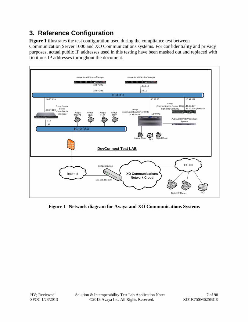
3. Reference Configuration Figure 1 illustrates the test configuration used during the compliance test between
Communication Server 1000 and XO Communications systems. For confidentiality and privacy
purposes, actual public IP addresses used in this testing have been masked out and replaced with
fictitious IP addresses throughout the document.
Internet
PSTN
DevConnect Test LAB
Avaya Aura ® System Manager Avaya Aura ® Session Manager
Avaya
Communication Server 1000
Call Server
Avaya Session
Border
Controller for
Enterprise
Analog Phone Digital Phone
Digital/IP Phones
.10.97.96
.10.97.65
.33.1.11.10.97.196
.10.97.189
.112
.33.1.1.10.97.193
.10.97.129
.97
10.10.98.X
10.X.X.X
XO Communications
Network Cloud
Avaya Call Pilot Voicemail
System
Avaya
Communication Server 1000
Signaling Gateway
SONUS Switch
192.168.163.138
.10.97.129
.10.97.177
.10.97.178 (Node ID)
FAX
FAX
Avaya
2002P2
Avaya
1140
Avaya
1120
Avaya
2007
Figure 1- Network diagram for Avaya and XO Communications Systems
HV; Reviewed:
SPOC 1/28/2013
Solution & Interoperability Test Lab Application Notes
©2013 Avaya Inc. All Rights Reserved.
8 of 90
XO1K75SM62SBCE
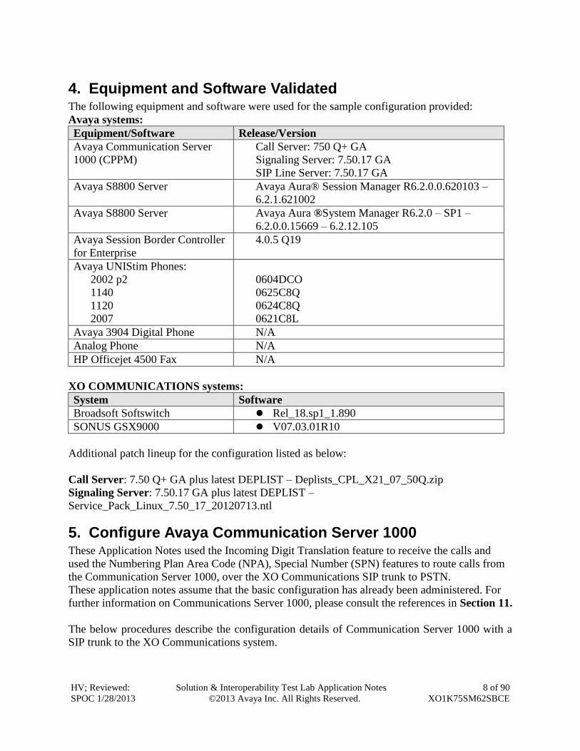
4. Equipment and Software Validated The following equipment and software were used for the sample configuration provided:
Avaya systems:
Equipment/Software Release/Version
Avaya Communication Server
1000 (CPPM)
Call Server: 750 Q+ GA
Signaling Server: 7.50.17 GA
SIP Line Server: 7.50.17 GA
Avaya S8800 Server Avaya Aura® Session Manager R6.2.0.0.620103 –
6.2.1.621002
Avaya S8800 Server Avaya Aura ®System Manager R6.2.0 – SP1 –
6.2.0.0.15669 – 6.2.12.105
Avaya Session Border Controller
for Enterprise
4.0.5 Q19
Avaya UNIStim Phones:
2002 p2
1140
1120
2007
0604DCO
0625C8Q
0624C8Q
0621C8L
Avaya 3904 Digital Phone N/A
Analog Phone N/A
HP Officejet 4500 Fax N/A
XO COMMUNICATIONS systems:
System Software
Broadsoft Softswitch Rel_18.sp1_1.890
SONUS GSX9000 V07.03.01R10
Additional patch lineup for the configuration listed as below:
Call Server: 7.50 Q+ GA plus latest DEPLIST – Deplists_CPL_X21_07_50Q.zip
Signaling Server: 7.50.17 GA plus latest DEPLIST –
Service_Pack_Linux_7.50_17_20120713.ntl
5. Configure Avaya Communication Server 1000 These Application Notes used the Incoming Digit Translation feature to receive the calls and
used the Numbering Plan Area Code (NPA), Special Number (SPN) features to route calls from
the Communication Server 1000, over the XO Communications SIP trunk to PSTN.
These application notes assume that the basic configuration has already been administered. For
further information on Communications Server 1000, please consult the references in Section 11.
The below procedures describe the configuration details of Communication Server 1000 with a
SIP trunk to the XO Communications system.
HV; Reviewed:
SPOC 1/28/2013
Solution & Interoperability Test Lab Application Notes
©2013 Avaya Inc. All Rights Reserved.
9 of 90
XO1K75SM62SBCE
5.1. Log in to Communication Server 1000 System
5.1.1. Log in to Unified Communications Management (UCM) and Element Manager (EM)
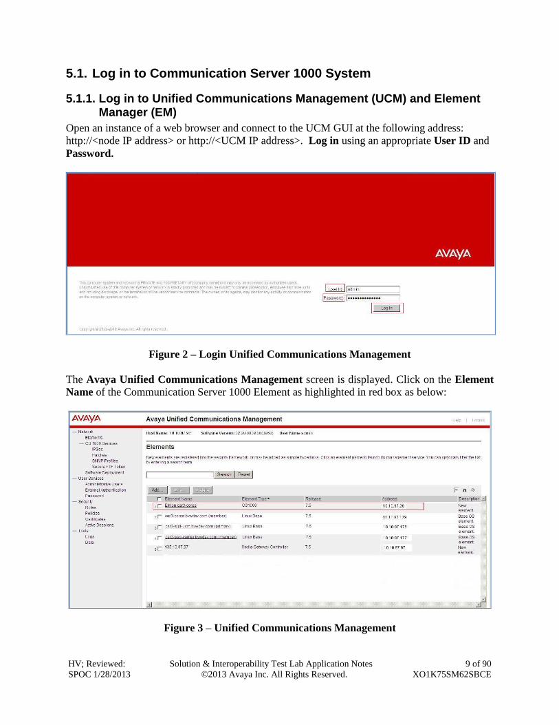
Open an instance of a web browser and connect to the UCM GUI at the following address:
http://<node IP address> or http://<UCM IP address>. Log in using an appropriate User ID and
Password.
Figure 2 – Login Unified Communications Management
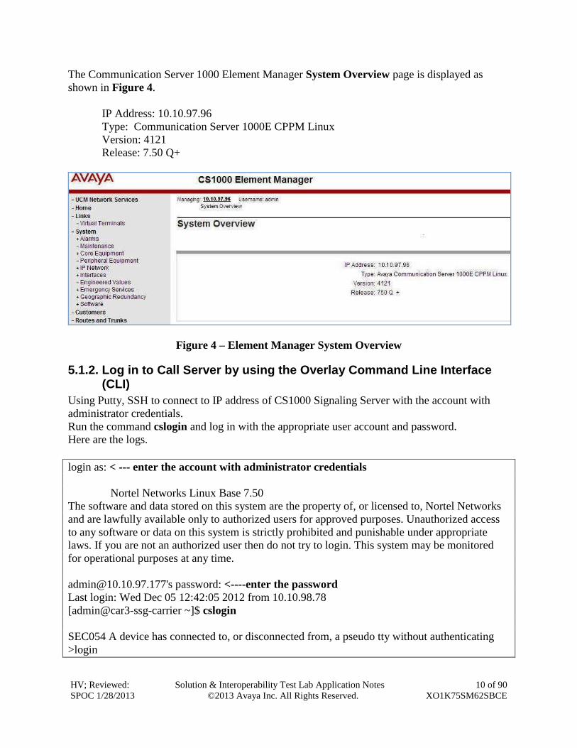
The Avaya Unified Communications Management screen is displayed. Click on the Element
Name of the Communication Server 1000 Element as highlighted in red box as below:
Figure 3 – Unified Communications Management
HV; Reviewed:
SPOC 1/28/2013
Solution & Interoperability Test Lab Application Notes
©2013 Avaya Inc. All Rights Reserved.
10 of 90
XO1K75SM62SBCE
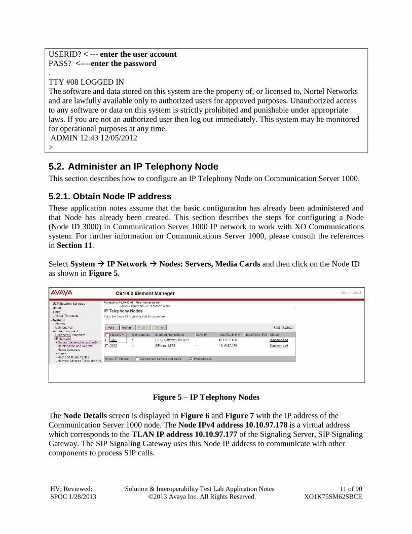
The Communication Server 1000 Element Manager System Overview page is displayed as
shown in Figure 4.
IP Address: 10.10.97.96
Type: Communication Server 1000E CPPM Linux
Version: 4121
Release: 7.50 Q+
Figure 4 – Element Manager System Overview
5.1.2. Log in to Call Server by using the Overlay Command Line Interface (CLI)
Using Putty, SSH to connect to IP address of CS1000 Signaling Server with the account with
administrator credentials.
Run the command cslogin and log in with the appropriate user account and password.
Here are the logs.
login as: < --- enter the account with administrator credentials
Nortel Networks Linux Base 7.50
The software and data stored on this system are the property of, or licensed to, Nortel Networks
and are lawfully available only to authorized users for approved purposes. Unauthorized access
to any software or data on this system is strictly prohibited and punishable under appropriate
laws. If you are not an authorized user then do not try to login. This system may be monitored
for operational purposes at any time.
[email protected]'s password: <----enter the password
Last login: Wed Dec 05 12:42:05 2012 from 10.10.98.78
[admin@car3-ssg-carrier ~]$ cslogin
SEC054 A device has connected to, or disconnected from, a pseudo tty without authenticating
>login
HV; Reviewed:
SPOC 1/28/2013
Solution & Interoperability Test Lab Application Notes
©2013 Avaya Inc. All Rights Reserved.
11 of 90
XO1K75SM62SBCE
USERID? < --- enter the user account
PASS? <----enter the password
.
TTY #08 LOGGED IN
The software and data stored on this system are the property of, or licensed to, Nortel Networks
and are lawfully available only to authorized users for approved purposes. Unauthorized access
to any software or data on this system is strictly prohibited and punishable under appropriate
laws. If you are not an authorized user then log out immediately. This system may be monitored
for operational purposes at any time.
ADMIN 12:43 12/05/2012
>
5.2. Administer an IP Telephony Node
This section describes how to configure an IP Telephony Node on Communication Server 1000.
5.2.1. Obtain Node IP address
These application notes assume that the basic configuration has already been administered and
that Node has already been created. This section describes the steps for configuring a Node
(Node ID 3000) in Communication Server 1000 IP network to work with XO Communications
system. For further information on Communications Server 1000, please consult the references
in Section 11.
Select System IP Network Nodes: Servers, Media Cards and then click on the Node ID
as shown in Figure 5.
Figure 5 – IP Telephony Nodes
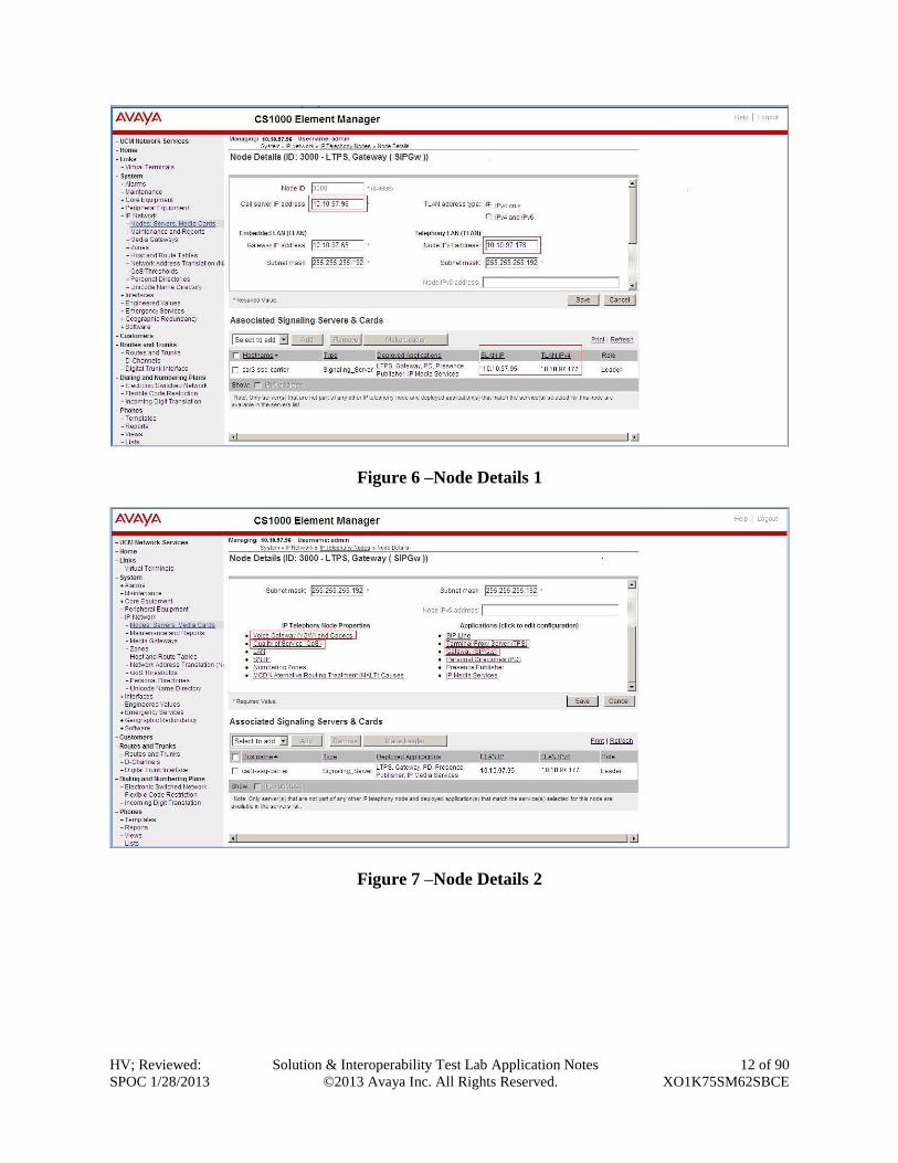
The Node Details screen is displayed in Figure 6 and Figure 7 with the IP address of the
Communication Server 1000 node. The Node IPv4 address 10.10.97.178 is a virtual address
which corresponds to the TLAN IP address 10.10.97.177 of the Signaling Server, SIP Signaling
Gateway. The SIP Signaling Gateway uses this Node IP address to communicate with other
components to process SIP calls.
HV; Reviewed:
SPOC 1/28/2013
Solution & Interoperability Test Lab Application Notes
©2013 Avaya Inc. All Rights Reserved.
12 of 90
XO1K75SM62SBCE
Figure 6 –Node Details 1
Figure 7 –Node Details 2
HV; Reviewed:
SPOC 1/28/2013
Solution & Interoperability Test Lab Application Notes
©2013 Avaya Inc. All Rights Reserved.
13 of 90
XO1K75SM62SBCE
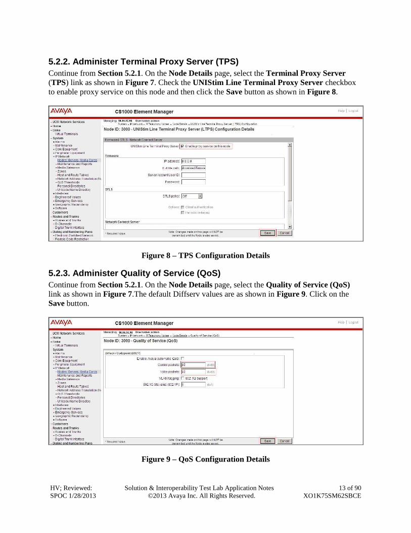
5.2.2. Administer Terminal Proxy Server (TPS)
Continue from Section 5.2.1. On the Node Details page, select the Terminal Proxy Server
(TPS) link as shown in Figure 7. Check the UNIStim Line Terminal Proxy Server checkbox
to enable proxy service on this node and then click the Save button as shown in Figure 8.
Figure 8 – TPS Configuration Details
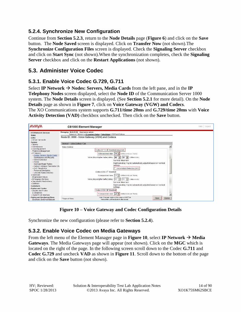
5.2.3. Administer Quality of Service (QoS)
Continue from Section 5.2.1. On the Node Details page, select the Quality of Service (QoS)
link as shown in Figure 7.The default Diffserv values are as shown in Figure 9. Click on the
Save button.
Figure 9 – QoS Configuration Details
HV; Reviewed:
SPOC 1/28/2013
Solution & Interoperability Test Lab Application Notes
©2013 Avaya Inc. All Rights Reserved.
14 of 90
XO1K75SM62SBCE
5.2.4. Synchronize New Configuration
Continue from Section 5.2.3, return to the Node Details page (Figure 6) and click on the Save
button. The Node Saved screen is displayed. Click on Transfer Now (not shown).The
Synchronize Configuration Files screen is displayed. Check the Signaling Server checkbox
and click on Start Sync (not shown).When the synchronization completes, check the Signaling
Server checkbox and click on the Restart Applications (not shown).
5.3. Administer Voice Codec
5.3.1. Enable Voice Codec G.729, G.711
Select IP Network Nodes: Servers, Media Cards from the left pane, and in the IP
Telephony Nodes screen displayed, select the Node ID of the Communication Server 1000
system. The Node Details screen is displayed. (See Section 5.2.1 for more detail). On the Node
Details page as shown in Figure 7, click on Voice Gateway (VGW) and Codecs.
The XO Communications system supports G.711/time 20ms and G.729/time 20ms with Voice
Activity Detection (VAD) checkbox unchecked. Then click on the Save button.
Figure 10 – Voice Gateway and Codec Configuration Details
Synchronize the new configuration (please refer to Section 5.2.4).
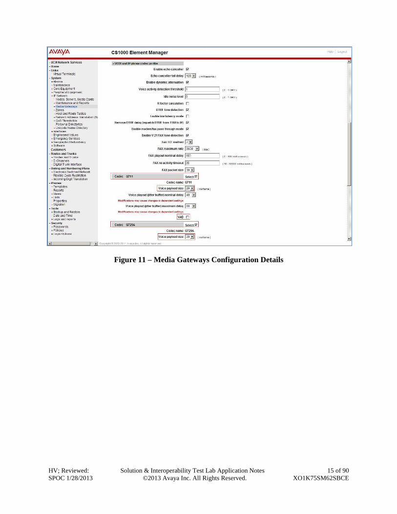
5.3.2. Enable Voice Codec on Media Gateways
From the left menu of the Element Manager page in Figure 10, select IP Network Media
Gateways. The Media Gateways page will appear (not shown). Click on the MGC which is
located on the right of the page. In the following screen scroll down to the Codec G.711 and
Codec G.729 and uncheck VAD as shown in Figure 11. Scroll down to the bottom of the page
and click on the Save button (not shown).
HV; Reviewed:
SPOC 1/28/2013
Solution & Interoperability Test Lab Application Notes
©2013 Avaya Inc. All Rights Reserved.
15 of 90
XO1K75SM62SBCE
Figure 11 – Media Gateways Configuration Details
HV; Reviewed:
SPOC 1/28/2013
Solution & Interoperability Test Lab Application Notes
©2013 Avaya Inc. All Rights Reserved.
16 of 90
XO1K75SM62SBCE
5.4. Zones and Bandwidth Management
This section describes the steps to create 2 zones: zone 10 for VGW and IP set, and zone 255 for
SIP Trunk.
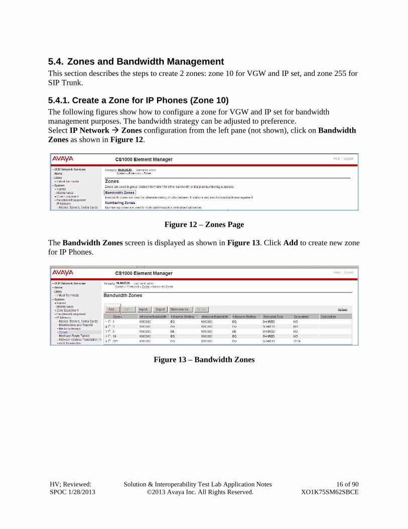
5.4.1. Create a Zone for IP Phones (Zone 10)
The following figures show how to configure a zone for VGW and IP set for bandwidth
management purposes. The bandwidth strategy can be adjusted to preference.
Select IP Network Zones configuration from the left pane (not shown), click on Bandwidth
Zones as shown in Figure 12.
Figure 12 – Zones Page
The Bandwidth Zones screen is displayed as shown in Figure 13. Click Add to create new zone
for IP Phones.
Figure 13 – Bandwidth Zones
HV; Reviewed:
SPOC 1/28/2013
Solution & Interoperability Test Lab Application Notes
©2013 Avaya Inc. All Rights Reserved.
17 of 90
XO1K75SM62SBCE
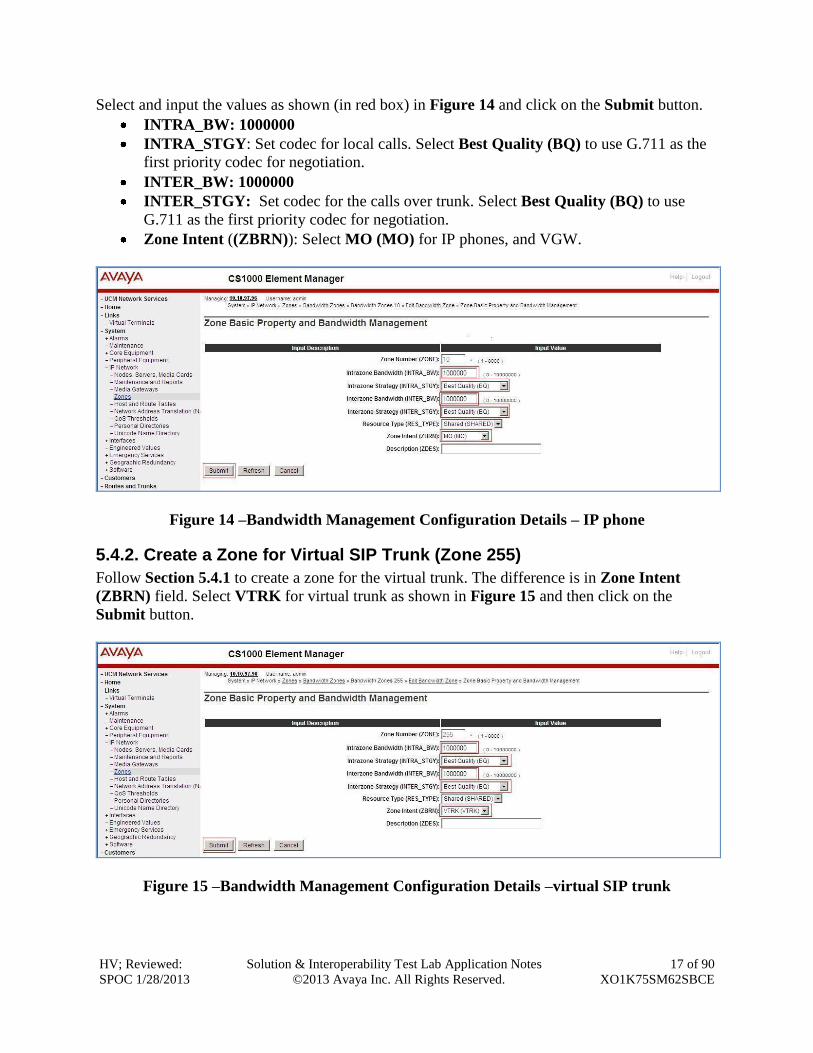
Select and input the values as shown (in red box) in Figure 14 and click on the Submit button.
INTRA_BW: 1000000
INTRA_STGY: Set codec for local calls. Select Best Quality (BQ) to use G.711 as the
first priority codec for negotiation.
INTER_BW: 1000000
INTER_STGY: Set codec for the calls over trunk. Select Best Quality (BQ) to use
G.711 as the first priority codec for negotiation.
Zone Intent ((ZBRN)): Select MO (MO) for IP phones, and VGW.
Figure 14 –Bandwidth Management Configuration Details – IP phone
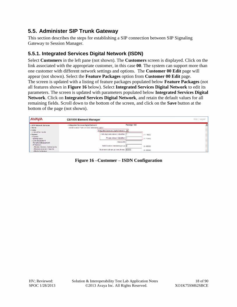
5.4.2. Create a Zone for Virtual SIP Trunk (Zone 255)
Follow Section 5.4.1 to create a zone for the virtual trunk. The difference is in Zone Intent
(ZBRN) field. Select VTRK for virtual trunk as shown in Figure 15 and then click on the
Submit button.
Figure 15 –Bandwidth Management Configuration Details –virtual SIP trunk
HV; Reviewed:
SPOC 1/28/2013
Solution & Interoperability Test Lab Application Notes
©2013 Avaya Inc. All Rights Reserved.
18 of 90
XO1K75SM62SBCE
5.5. Administer SIP Trunk Gateway
This section describes the steps for establishing a SIP connection between SIP Signaling
Gateway to Session Manager.
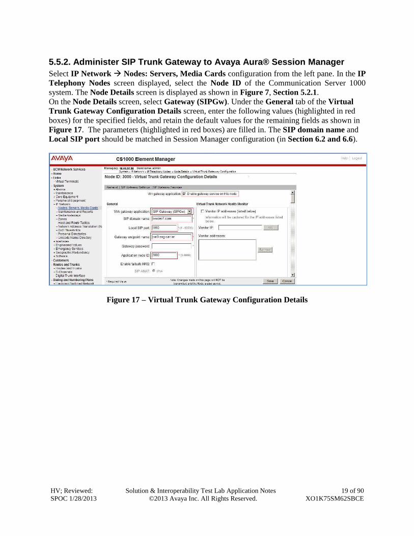
5.5.1. Integrated Services Digital Network (ISDN)
Select Customers in the left pane (not shown). The Customers screen is displayed. Click on the
link associated with the appropriate customer, in this case 00. The system can support more than
one customer with different network settings and options. The Customer 00 Edit page will
appear (not shown). Select the Feature Packages option from Customer 00 Edit page.
The screen is updated with a listing of feature packages populated below Feature Packages (not
all features shown in Figure 16 below). Select Integrated Services Digital Network to edit its
parameters. The screen is updated with parameters populated below Integrated Services Digital
Network. Click on Integrated Services Digital Network, and retain the default values for all
remaining fields. Scroll down to the bottom of the screen, and click on the Save button at the
bottom of the page (not shown).
Figure 16 –Customer – ISDN Configuration
HV; Reviewed:
SPOC 1/28/2013
Solution & Interoperability Test Lab Application Notes
©2013 Avaya Inc. All Rights Reserved.
19 of 90
XO1K75SM62SBCE
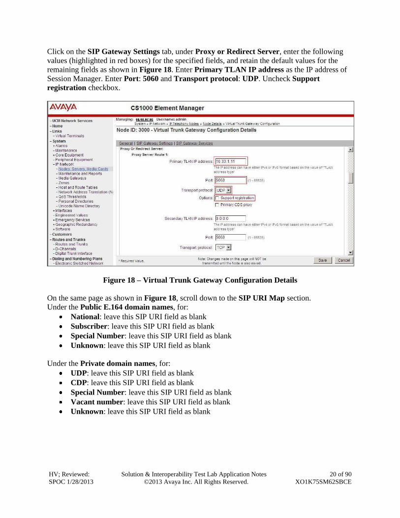
5.5.2. Administer SIP Trunk Gateway to Avaya Aura® Session Manager
Select IP Network Nodes: Servers, Media Cards configuration from the left pane. In the IP
Telephony Nodes screen displayed, select the Node ID of the Communication Server 1000
system. The Node Details screen is displayed as shown in Figure 7, Section 5.2.1.
On the Node Details screen, select Gateway (SIPGw). Under the General tab of the Virtual
Trunk Gateway Configuration Details screen, enter the following values (highlighted in red
boxes) for the specified fields, and retain the default values for the remaining fields as shown in
Figure 17. The parameters (highlighted in red boxes) are filled in. The SIP domain name and
Local SIP port should be matched in Session Manager configuration (in Section 6.2 and 6.6).
Figure 17 – Virtual Trunk Gateway Configuration Details
HV; Reviewed:
SPOC 1/28/2013
Solution & Interoperability Test Lab Application Notes
©2013 Avaya Inc. All Rights Reserved.
20 of 90
XO1K75SM62SBCE
Click on the SIP Gateway Settings tab, under Proxy or Redirect Server, enter the following
values (highlighted in red boxes) for the specified fields, and retain the default values for the
remaining fields as shown in Figure 18. Enter Primary TLAN IP address as the IP address of
Session Manager. Enter Port: 5060 and Transport protocol: UDP. Uncheck Support
registration checkbox.
Figure 18 – Virtual Trunk Gateway Configuration Details
On the same page as shown in Figure 18, scroll down to the SIP URI Map section.
Under the Public E.164 domain names, for:
National: leave this SIP URI field as blank
Subscriber: leave this SIP URI field as blank
Special Number: leave this SIP URI field as blank
Unknown: leave this SIP URI field as blank
Under the Private domain names, for:
UDP: leave this SIP URI field as blank
CDP: leave this SIP URI field as blank
Special Number: leave this SIP URI field as blank
Vacant number: leave this SIP URI field as blank
Unknown: leave this SIP URI field as blank
HV; Reviewed:
SPOC 1/28/2013
Solution & Interoperability Test Lab Application Notes
©2013 Avaya Inc. All Rights Reserved.
21 of 90
XO1K75SM62SBCE
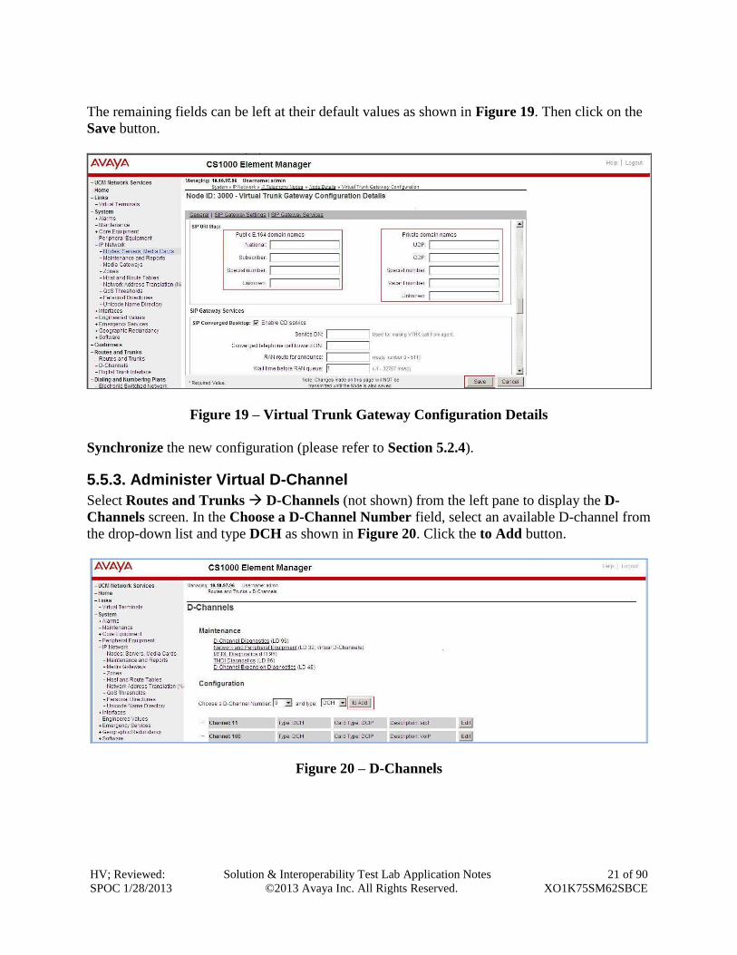
The remaining fields can be left at their default values as shown in Figure 19. Then click on the
Save button.
Figure 19 – Virtual Trunk Gateway Configuration Details
Synchronize the new configuration (please refer to Section 5.2.4).
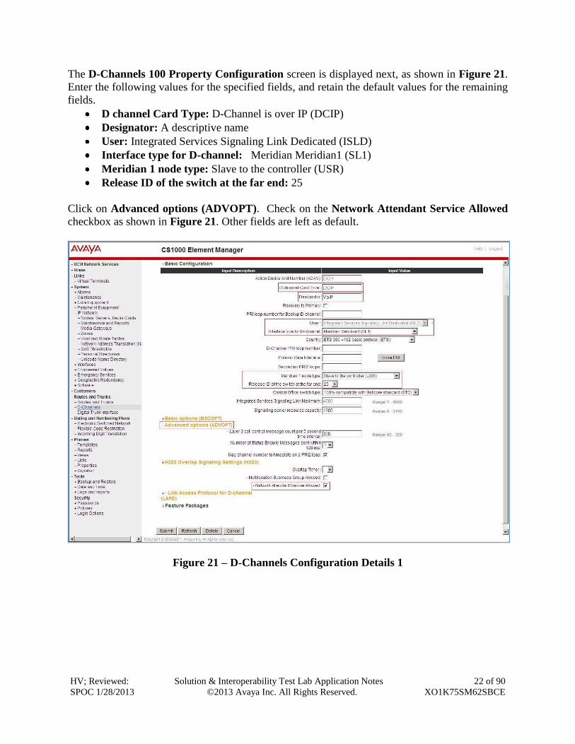
5.5.3. Administer Virtual D-Channel
Select Routes and Trunks D-Channels (not shown) from the left pane to display the D-
Channels screen. In the Choose a D-Channel Number field, select an available D-channel from
the drop-down list and type DCH as shown in Figure 20. Click the to Add button.
Figure 20 – D-Channels
HV; Reviewed:
SPOC 1/28/2013
Solution & Interoperability Test Lab Application Notes
©2013 Avaya Inc. All Rights Reserved.
22 of 90
XO1K75SM62SBCE
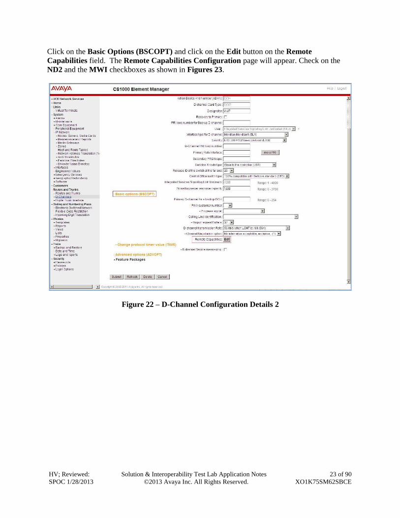
The D-Channels 100 Property Configuration screen is displayed next, as shown in Figure 21.
Enter the following values for the specified fields, and retain the default values for the remaining
fields.
D channel Card Type: D-Channel is over IP (DCIP)
Designator: A descriptive name
User: Integrated Services Signaling Link Dedicated (ISLD)
Interface type for D-channel: Meridian Meridian1 (SL1)
Meridian 1 node type: Slave to the controller (USR)
Release ID of the switch at the far end: 25
Click on Advanced options (ADVOPT). Check on the Network Attendant Service Allowed
checkbox as shown in Figure 21. Other fields are left as default.
Figure 21 – D-Channels Configuration Details 1
HV; Reviewed:
SPOC 1/28/2013
Solution & Interoperability Test Lab Application Notes
©2013 Avaya Inc. All Rights Reserved.
23 of 90
XO1K75SM62SBCE
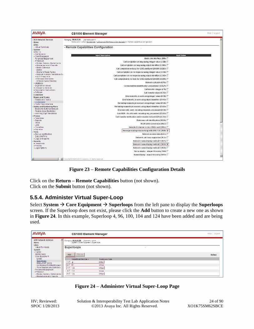
Click on the Basic Options (BSCOPT) and click on the Edit button on the Remote
Capabilities field. The Remote Capabilities Configuration page will appear. Check on the
ND2 and the MWI checkboxes as shown in Figures 23.
Figure 22 – D-Channel Configuration Details 2
HV; Reviewed:
SPOC 1/28/2013
Solution & Interoperability Test Lab Application Notes
©2013 Avaya Inc. All Rights Reserved.
24 of 90
XO1K75SM62SBCE
Figure 23 – Remote Capabilities Configuration Details
Click on the Return – Remote Capabilities button (not shown).
Click on the Submit button (not shown).
5.5.4. Administer Virtual Super-Loop
Select System Core Equipment Superloops from the left pane to display the Superloops
screen. If the Superloop does not exist, please click the Add button to create a new one as shown
in Figure 24. In this example, Superloop 4, 96, 100, 104 and 124 have been added and are being
used.
Figure 24 – Administer Virtual Super-Loop Page
HV; Reviewed:
SPOC 1/28/2013
Solution & Interoperability Test Lab Application Notes
©2013 Avaya Inc. All Rights Reserved.
25 of 90
XO1K75SM62SBCE
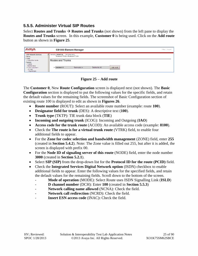
5.5.5. Administer Virtual SIP Routes
Select Routes and Trunks Routes and Trunks (not shown) from the left pane to display the
Routes and Trunks screen. In this example, Customer 0 is being used. Click on the Add route
button as shown in Figure 25.
Figure 25 – Add route
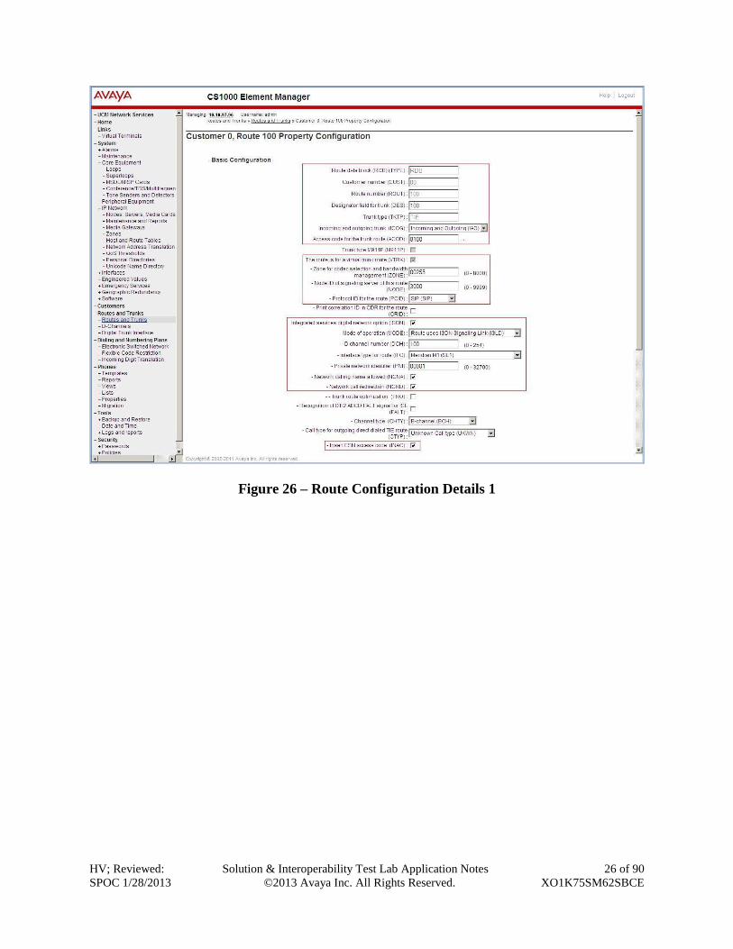
The Customer 0, New Route Configuration screen is displayed next (not shown). The Basic
Configuration section is displayed to put the following values for the specific fields, and retain
the default values for the remaining fields. The screenshot of Basic Configuration section of
existing route 100 is displayed to edit as shown in Figures 26.
Route number (ROUT): Select an available route number (example: route 100).
Designator field for trunk (DES): A descriptive text (100).
Trunk type (TKTP): TIE trunk data block (TIE)
Incoming and outgoing trunk (ICOG): Incoming and Outgoing (IAO)
Access code for the trunk route (ACOD): An available access code (example: 8100).
Check the The route is for a virtual trunk route (VTRK) field, to enable four
additional fields to appear.
For the Zone for codec selection and bandwidth management (ZONE) field, enter 255
(created in Section 5.4.2). Note: The Zone value is filled out 255, but after it is added, the
screen is displayed with prefix 00.
For the Node ID of signaling server of this route (NODE) field, enter the node number
3000 (created in Section 5.2.1).
Select SIP (SIP) from the drop-down list for the Protocol ID for the route (PCID) field.
Check the Integrated Services Digital Network option (ISDN) checkbox to enable
additional fields to appear. Enter the following values for the specified fields, and retain
the default values for the remaining fields. Scroll down to the bottom of the screen.
- Mode of operation (MODE): Select Route uses ISDN Signalling Link (ISLD)
- D channel number (DCH): Enter 100 (created in Section 5.5.3)
- Network calling name allowed (NCNA): Check the field.
- Network call redirection (NCRD): Check the field.
- Insert ESN access code (INAC): Check the field.
HV; Reviewed:
SPOC 1/28/2013
Solution & Interoperability Test Lab Application Notes
©2013 Avaya Inc. All Rights Reserved.
26 of 90
XO1K75SM62SBCE
Figure 26 – Route Configuration Details 1
HV; Reviewed:
SPOC 1/28/2013
Solution & Interoperability Test Lab Application Notes
©2013 Avaya Inc. All Rights Reserved.
27 of 90
XO1K75SM62SBCE
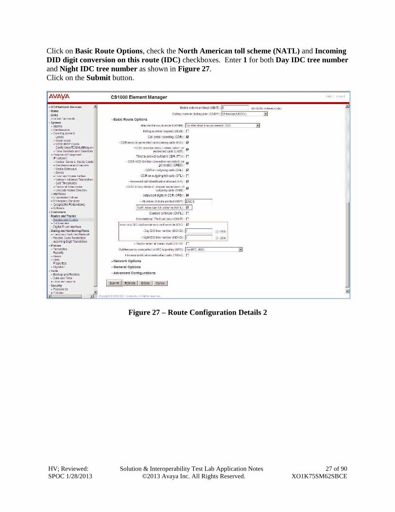
Click on Basic Route Options, check the North American toll scheme (NATL) and Incoming
DID digit conversion on this route (IDC) checkboxes. Enter 1 for both Day IDC tree number
and Night IDC tree number as shown in Figure 27.
Click on the Submit button.
Figure 27 – Route Configuration Details 2
HV; Reviewed:
SPOC 1/28/2013
Solution & Interoperability Test Lab Application Notes
©2013 Avaya Inc. All Rights Reserved.
28 of 90
XO1K75SM62SBCE
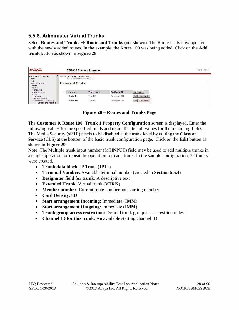
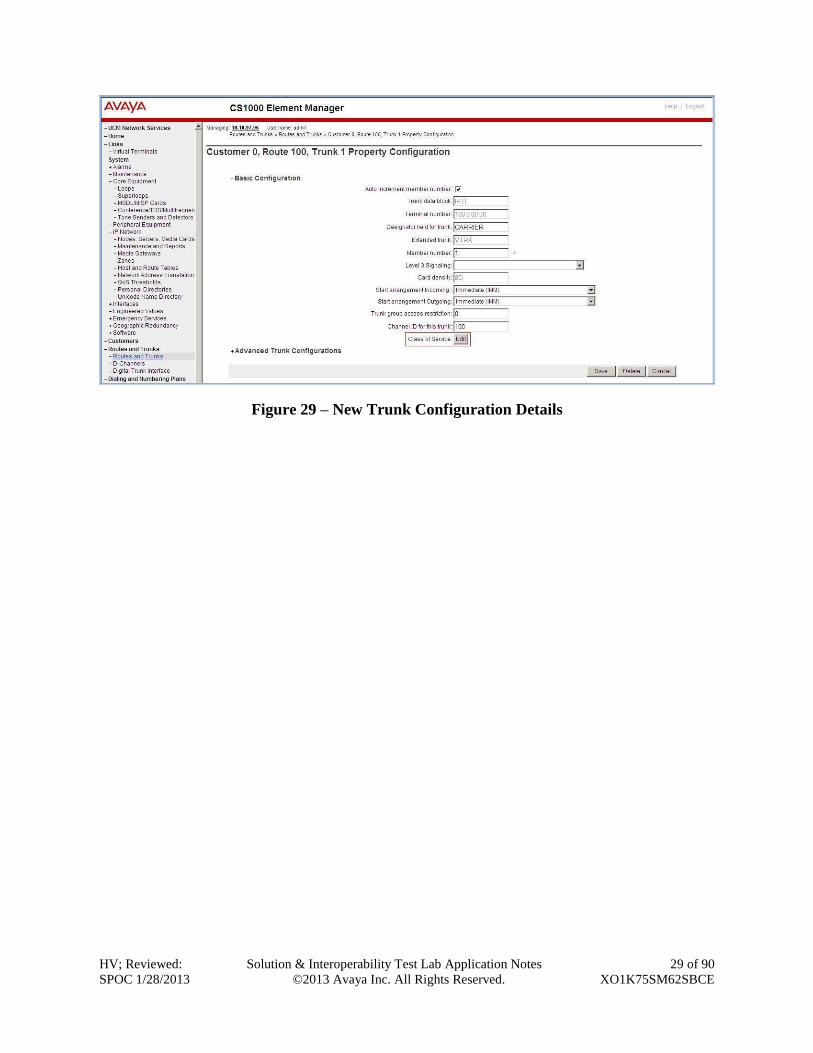
5.5.6. Administer Virtual Trunks
Select Routes and Trunks Route and Trunks (not shown). The Route list is now updated
with the newly added routes. In the example, the Route 100 was being added. Click on the Add
trunk button as shown in Figure 28.
Figure 28 – Routes and Trunks Page
The Customer 0, Route 100, Trunk 1 Property Configuration screen is displayed. Enter the
following values for the specified fields and retain the default values for the remaining fields.
The Media Security (sRTP) needs to be disabled at the trunk level by editing the Class of
Service (CLS) at the bottom of the basic trunk configuration page. Click on the Edit button as
shown in Figure 29.
Note: The Multiple trunk input number (MTINPUT) field may be used to add multiple trunks in
a single operation, or repeat the operation for each trunk. In the sample configuration, 32 trunks
were created.
Trunk data block: IP Trunk (IPTI)
Terminal Number: Available terminal number (created in Section 5.5.4)
Designator field for trunk: A descriptive text
Extended Trunk: Virtual trunk (VTRK)
Member number: Current route number and starting member
Card Density: 8D
Start arrangement Incoming: Immediate (IMM)
Start arrangement Outgoing: Immediate (IMM)
Trunk group access restriction: Desired trunk group access restriction level
Channel ID for this trunk: An available starting channel ID
HV; Reviewed:
SPOC 1/28/2013
Solution & Interoperability Test Lab Application Notes
©2013 Avaya Inc. All Rights Reserved.
29 of 90
XO1K75SM62SBCE
Figure 29 – New Trunk Configuration Details

HV; Reviewed:
SPOC 1/28/2013
Solution & Interoperability Test Lab Application Notes
©2013 Avaya Inc. All Rights Reserved.
30 of 90
XO1K75SM62SBCE
For Media Security, select Media Security Never (MSNV). Enter the remaining values for the
specified fields as shown in Figure 30. Scroll down to the bottom of the screen and click Return
Class of Service and click on the Save button (not shown).
Figure 30 – Class of Service Configuration Details Page
HV; Reviewed:
SPOC 1/28/2013
Solution & Interoperability Test Lab Application Notes
©2013 Avaya Inc. All Rights Reserved.
31 of 90
XO1K75SM62SBCE
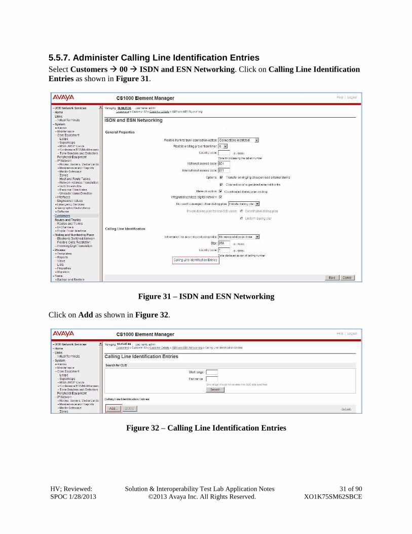
5.5.7. Administer Calling Line Identification Entries
Select Customers 00 ISDN and ESN Networking. Click on Calling Line Identification
Entries as shown in Figure 31.
Figure 31 – ISDN and ESN Networking
Click on Add as shown in Figure 32.
Figure 32 – Calling Line Identification Entries
HV; Reviewed:
SPOC 1/28/2013
Solution & Interoperability Test Lab Application Notes
©2013 Avaya Inc. All Rights Reserved.
32 of 90
XO1K75SM62SBCE
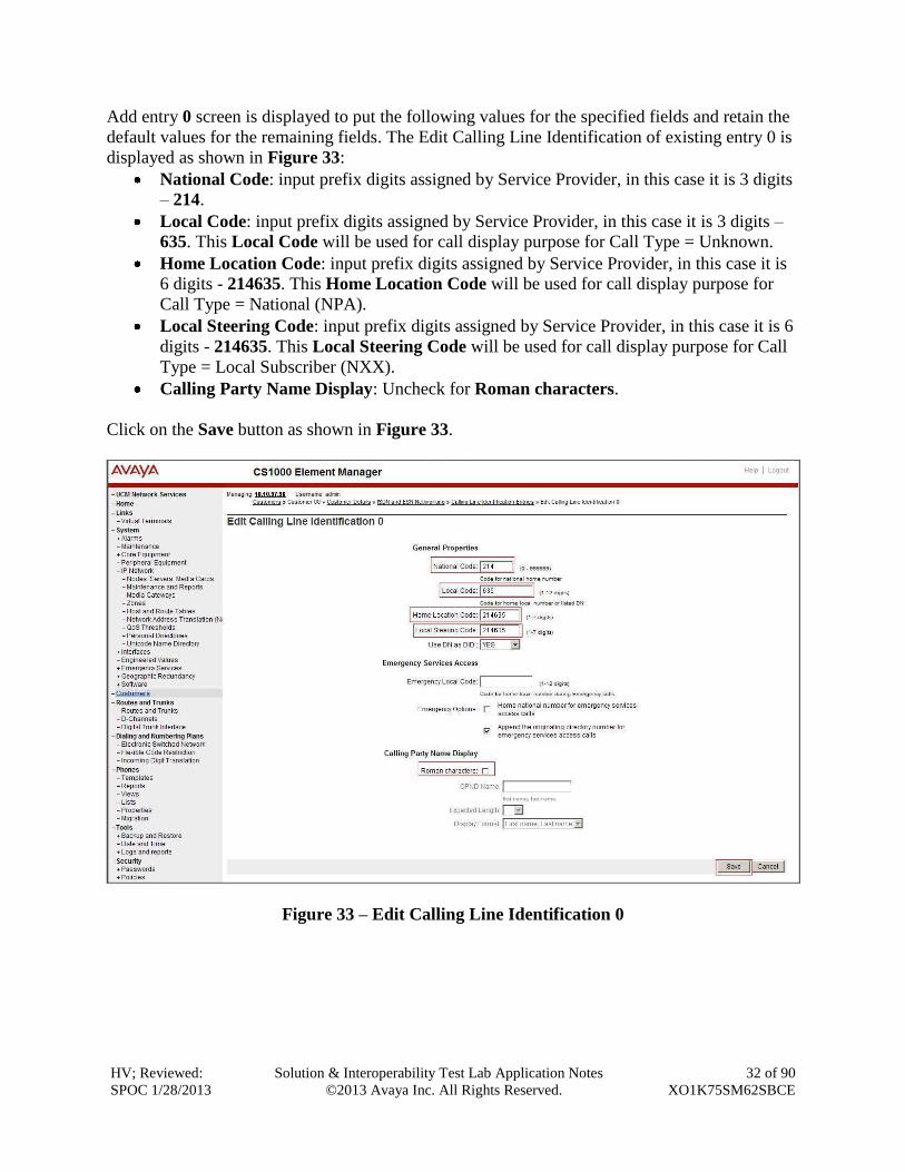
Add entry 0 screen is displayed to put the following values for the specified fields and retain the
default values for the remaining fields. The Edit Calling Line Identification of existing entry 0 is
displayed as shown in Figure 33:
National Code: input prefix digits assigned by Service Provider, in this case it is 3 digits
– 214.
Local Code: input prefix digits assigned by Service Provider, in this case it is 3 digits –
635. This Local Code will be used for call display purpose for Call Type = Unknown.
Home Location Code: input prefix digits assigned by Service Provider, in this case it is
6 digits - 214635. This Home Location Code will be used for call display purpose for
Call Type = National (NPA).
Local Steering Code: input prefix digits assigned by Service Provider, in this case it is 6
digits - 214635. This Local Steering Code will be used for call display purpose for Call
Type = Local Subscriber (NXX).
Calling Party Name Display: Uncheck for Roman characters.
Click on the Save button as shown in Figure 33.
Figure 33 – Edit Calling Line Identification 0
HV; Reviewed:
SPOC 1/28/2013
Solution & Interoperability Test Lab Application Notes
©2013 Avaya Inc. All Rights Reserved.
33 of 90
XO1K75SM62SBCE
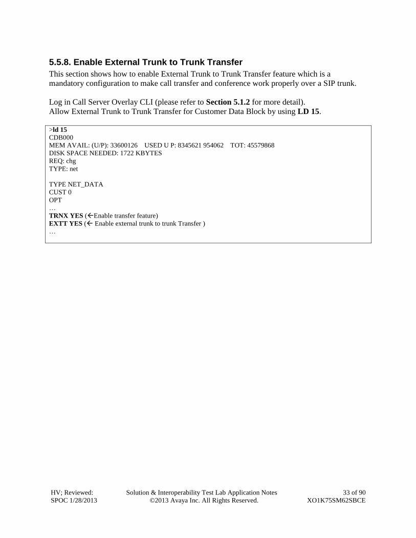
5.5.8. Enable External Trunk to Trunk Transfer
This section shows how to enable External Trunk to Trunk Transfer feature which is a
mandatory configuration to make call transfer and conference work properly over a SIP trunk.
Log in Call Server Overlay CLI (please refer to Section 5.1.2 for more detail).
Allow External Trunk to Trunk Transfer for Customer Data Block by using LD 15.
>ld 15
CDB000
MEM AVAIL: (U/P): 33600126 USED U P: 8345621 954062 TOT: 45579868
DISK SPACE NEEDED: 1722 KBYTES
REQ: chg
TYPE: net
TYPE NET_DATA
CUST 0
OPT
…
TRNX YES (Enable transfer feature)
EXTT YES ( Enable external trunk to trunk Transfer )
…
HV; Reviewed:
SPOC 1/28/2013
Solution & Interoperability Test Lab Application Notes
©2013 Avaya Inc. All Rights Reserved.
34 of 90
XO1K75SM62SBCE
5.6. Administer Dialing Plans
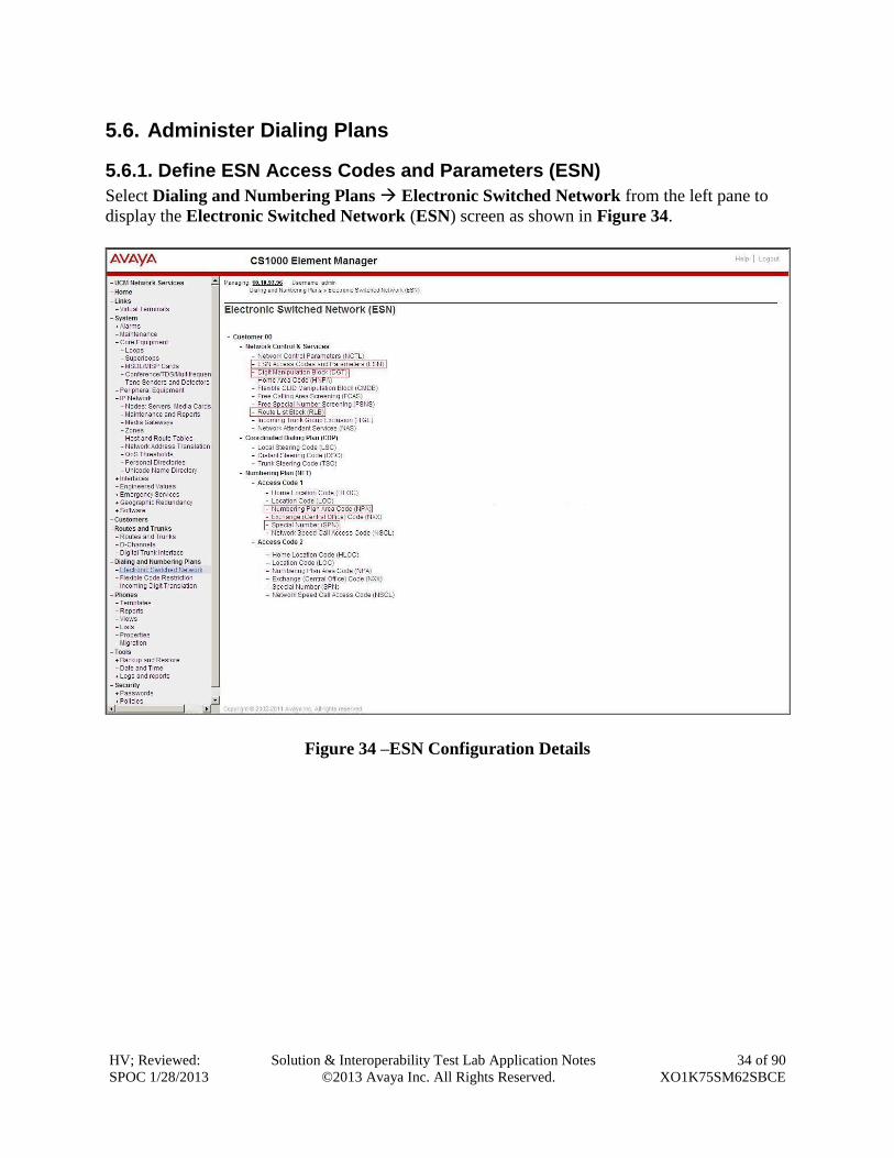
5.6.1. Define ESN Access Codes and Parameters (ESN)
Select Dialing and Numbering Plans Electronic Switched Network from the left pane to
display the Electronic Switched Network (ESN) screen as shown in Figure 34.
Figure 34 –ESN Configuration Details
HV; Reviewed:
SPOC 1/28/2013
Solution & Interoperability Test Lab Application Notes
©2013 Avaya Inc. All Rights Reserved.
35 of 90
XO1K75SM62SBCE
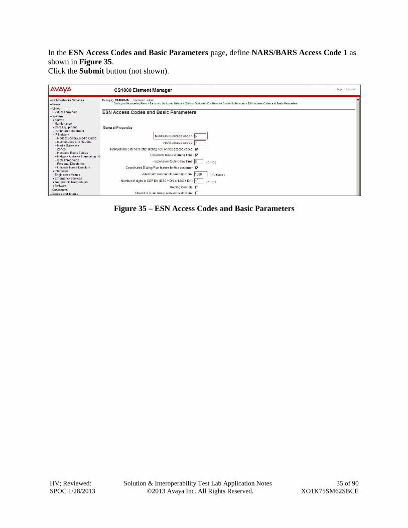
In the ESN Access Codes and Basic Parameters page, define NARS/BARS Access Code 1 as
shown in Figure 35.
Click the Submit button (not shown).
Figure 35 – ESN Access Codes and Basic Parameters
HV; Reviewed:
SPOC 1/28/2013
Solution & Interoperability Test Lab Application Notes
©2013 Avaya Inc. All Rights Reserved.
36 of 90
XO1K75SM62SBCE
5.6.2. Associate NPA and SPN call to ESN Access Code 1
Log in Call Server CLI (please refer to Section 5.1.2 for more detail), change Customer Net Data
block by using LD 15.
>ld 15
CDB000
MEM AVAIL: (U/P): 35600086 USED U P: 8325631 954152 TOT: 44879869
DISK SPACE NEEDED: 1722 KBYTES
REQ: chg
TYPE: net
TYPE NET_DATA
CUST 0
OPT
AC2 xNPA xSPN (Set NPA, SPN not to associate to ESN Access Code 2)
FNP
CLID
…
Verify Customer Net Data block by using LD 21.
>ld 21
PT1000
REQ: prt
TYPE: net
TYPE NET_DATA
CUST 0
TYPE NET_DATA
CUST 00
OPT RTA
AC1 INTL NPA SPN NXX LOC ------ > (NPA, SPN are associated to ESN Access Code 1)
AC2
FNP YES
…
HV; Reviewed:
SPOC 1/28/2013
Solution & Interoperability Test Lab Application Notes
©2013 Avaya Inc. All Rights Reserved.
37 of 90
XO1K75SM62SBCE
5.6.3. Digit Manipulation Block (DMI)
Select Dialing and Numbering Plans Electronic Switched Network (not shown) from the
left pane to display the Electronic Switched Network (ESN) screen. Select Digit Manipulation
Block (DGT) as shown in Figure 34. Select an available DMI from the drop-down list and click
to Add as shown in Figure 36
Enter the Number of leading digits to be Deleted (Del) field and select the Call Type to be
used by the manipulated digits (CTYP) and then click Submit (see Figure 37, Figure 38).
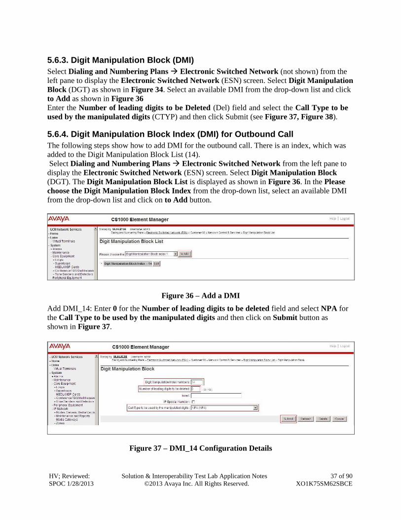
5.6.4. Digit Manipulation Block Index (DMI) for Outbound Call
The following steps show how to add DMI for the outbound call. There is an index, which was
added to the Digit Manipulation Block List (14).
Select Dialing and Numbering Plans Electronic Switched Network from the left pane to
display the Electronic Switched Network (ESN) screen. Select Digit Manipulation Block
(DGT). The Digit Manipulation Block List is displayed as shown in Figure 36. In the Please
choose the Digit Manipulation Block Index from the drop-down list, select an available DMI
from the drop-down list and click on to Add button.
Figure 36 – Add a DMI
Add DMI_14: Enter 0 for the Number of leading digits to be deleted field and select NPA for
the Call Type to be used by the manipulated digits and then click on Submit button as
shown in Figure 37.
Figure 37 – DMI_14 Configuration Details
HV; Reviewed:
SPOC 1/28/2013
Solution & Interoperability Test Lab Application Notes
©2013 Avaya Inc. All Rights Reserved.
38 of 90
XO1K75SM62SBCE
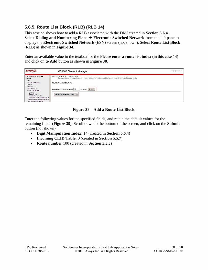
5.6.5. Route List Block (RLB) (RLB 14)
This session shows how to add a RLB associated with the DMI created in Section 5.6.4.
Select Dialing and Numbering Plans Electronic Switched Network from the left pane to
display the Electronic Switched Network (ESN) screen (not shown). Select Route List Block
(RLB) as shown in Figure 34.
Enter an available value in the textbox for the Please enter a route list index (in this case 14)
and click on to Add button as shown in Figure 38.
Figure 38 – Add a Route List Block.
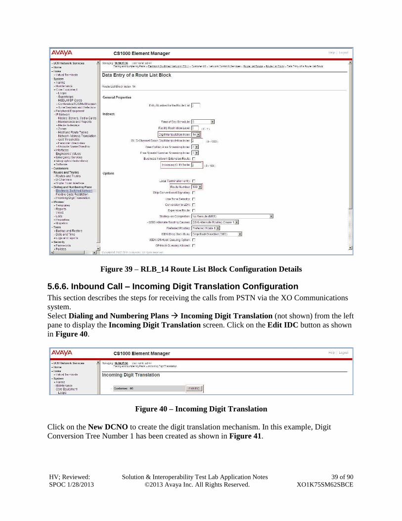
Enter the following values for the specified fields, and retain the default values for the
remaining fields (Figure 39). Scroll down to the bottom of the screen, and click on the Submit
button (not shown).
Digit Manipulation Index: 14 (created in Section 5.6.4)
Incoming CLID Table: 0 (created in Section 5.5.7)
Route number 100 (created in Section 5.5.5)
HV; Reviewed:
SPOC 1/28/2013
Solution & Interoperability Test Lab Application Notes
©2013 Avaya Inc. All Rights Reserved.
39 of 90
XO1K75SM62SBCE
Figure 39 – RLB_14 Route List Block Configuration Details
5.6.6. Inbound Call – Incoming Digit Translation Configuration
This section describes the steps for receiving the calls from PSTN via the XO Communications
system.
Select Dialing and Numbering Plans Incoming Digit Translation (not shown) from the left
pane to display the Incoming Digit Translation screen. Click on the Edit IDC button as shown
in Figure 40.
Figure 40 – Incoming Digit Translation
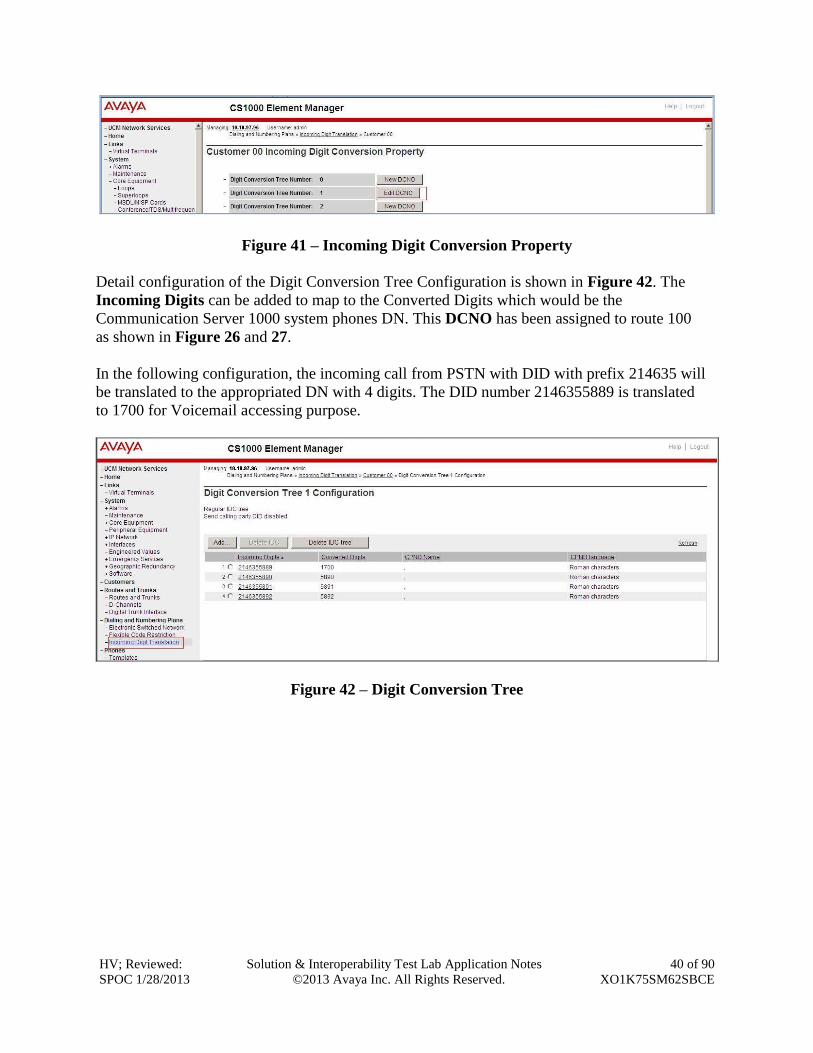
Click on the New DCNO to create the digit translation mechanism. In this example, Digit
Conversion Tree Number 1 has been created as shown in Figure 41.
HV; Reviewed:
SPOC 1/28/2013
Solution & Interoperability Test Lab Application Notes
©2013 Avaya Inc. All Rights Reserved.
40 of 90
XO1K75SM62SBCE
Figure 41 – Incoming Digit Conversion Property
Detail configuration of the Digit Conversion Tree Configuration is shown in Figure 42. The
Incoming Digits can be added to map to the Converted Digits which would be the
Communication Server 1000 system phones DN. This DCNO has been assigned to route 100
as shown in Figure 26 and 27.
In the following configuration, the incoming call from PSTN with DID with prefix 214635 will
be translated to the appropriated DN with 4 digits. The DID number 2146355889 is translated
to 1700 for Voicemail accessing purpose.
Figure 42 – Digit Conversion Tree
HV; Reviewed:
SPOC 1/28/2013
Solution & Interoperability Test Lab Application Notes
©2013 Avaya Inc. All Rights Reserved.
41 of 90
XO1K75SM62SBCE
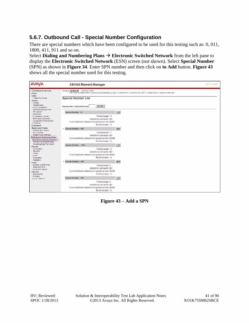
5.6.7. Outbound Call - Special Number Configuration
There are special numbers which have been configured to be used for this testing such as: 0, 011,
1800, 411, 911 and so on.
Select Dialing and Numbering Plans Electronic Switched Network from the left pane to
display the Electronic Switched Network (ESN) screen (not shown). Select Special Number
(SPN) as shown in Figure 34. Enter SPN number and then click on to Add button. Figure 43
shows all the special number used for this testing.
Figure 43 – Add a SPN
HV; Reviewed:
SPOC 1/28/2013
Solution & Interoperability Test Lab Application Notes
©2013 Avaya Inc. All Rights Reserved.
42 of 90
XO1K75SM62SBCE
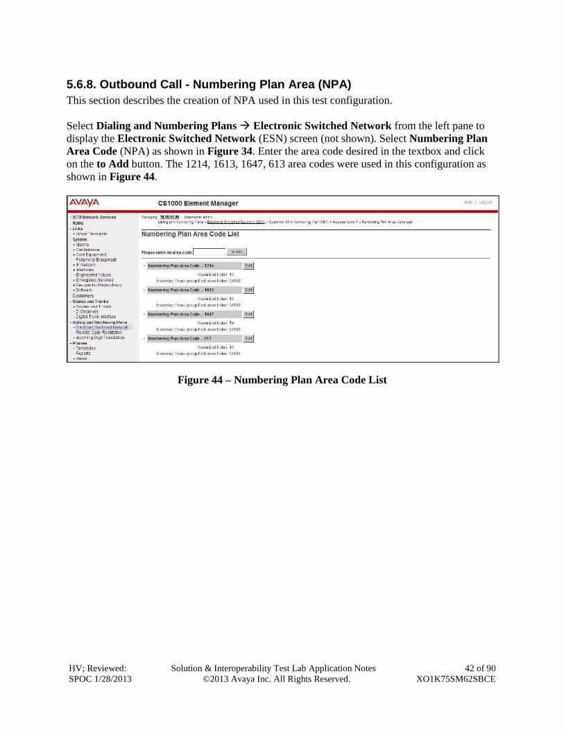
5.6.8. Outbound Call - Numbering Plan Area (NPA)
This section describes the creation of NPA used in this test configuration.
Select Dialing and Numbering Plans Electronic Switched Network from the left pane to
display the Electronic Switched Network (ESN) screen (not shown). Select Numbering Plan
Area Code (NPA) as shown in Figure 34. Enter the area code desired in the textbox and click
on the to Add button. The 1214, 1613, 1647, 613 area codes were used in this configuration as
shown in Figure 44.
Figure 44 – Numbering Plan Area Code List
HV; Reviewed:
SPOC 1/28/2013
Solution & Interoperability Test Lab Application Notes
©2013 Avaya Inc. All Rights Reserved.
43 of 90
XO1K75SM62SBCE
5.7. Administer Phone
This section describes the creation of Communication Server 1000 clients used in this
configuration.
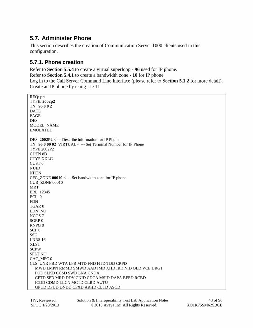
5.7.1. Phone creation
Refer to Section 5.5.4 to create a virtual superloop - 96 used for IP phone.
Refer to Section 5.4.1 to create a bandwidth zone - 10 for IP phone.
Log in to the Call Server Command Line Interface (please refer to Section 5.1.2 for more detail).
Create an IP phone by using LD 11
REQ: prt
TYPE: 2002p2
TN 96 0 0 2
DATE
PAGE
DES
MODEL_NAME
EMULATED
DES 2002P2 < --- Describe information for IP Phone
TN 96 0 00 02 VIRTUAL < --- Set Terminal Number for IP Phone
TYPE 2002P2
CDEN 8D
CTYP XDLC
CUST 0
NUID
NHTN
CFG_ZONE 00010 < --- Set bandwidth zone for IP phone
CUR_ZONE 00010
MRT
ERL 12345
ECL 0
FDN
TGAR 0
LDN NO
NCOS 7
SGRP 0
RNPG 0
SCI 0
SSU
LNRS 16
XLST
SCPW
SFLT NO
CAC_MFC 0
CLS UNR FBD WTA LPR MTD FND HTD TDD CRPD
MWD LMPN RMMD SMWD AAD IMD XHD IRD NID OLD VCE DRG1
POD SLKD CCSD SWD LNA CNDA
CFTD SFD MRD DDV CNID CDCA MSID DAPA BFED RCBD
ICDD CDMD LLCN MCTD CLBD AUTU
GPUD DPUD DNDD CFXD ARHD CLTD ASCD
HV; Reviewed:
SPOC 1/28/2013
Solution & Interoperability Test Lab Application Notes
©2013 Avaya Inc. All Rights Reserved.
44 of 90
XO1K75SM62SBCE
CPFA CPTA ABDD CFHD FICD NAID BUZZ AGRD MOAD
UDI RCC HBTD AHD IPND DDGA NAMA MIND PRSD NRWD NRCD NROD
DRDD EXR0
USMD USRD ULAD CCBD RTDD RBDD RBHD PGND OCBD FLXD FTTC DNDY DNO3 MCBN
FDSD NOVD VOLA VOUD CDMR PRED RECD MCDD T87D SBMD
MSNV FRA PKCH MWTD DVLD CROD ELCD
CPND_LANG ENG
HUNT
PLEV 02
PUID
UPWD
DANI NO
AST
IAPG 0
AACS NO
ITNA NO
DGRP
MLWU_LANG 0
MLNG ENG
DNDR 0
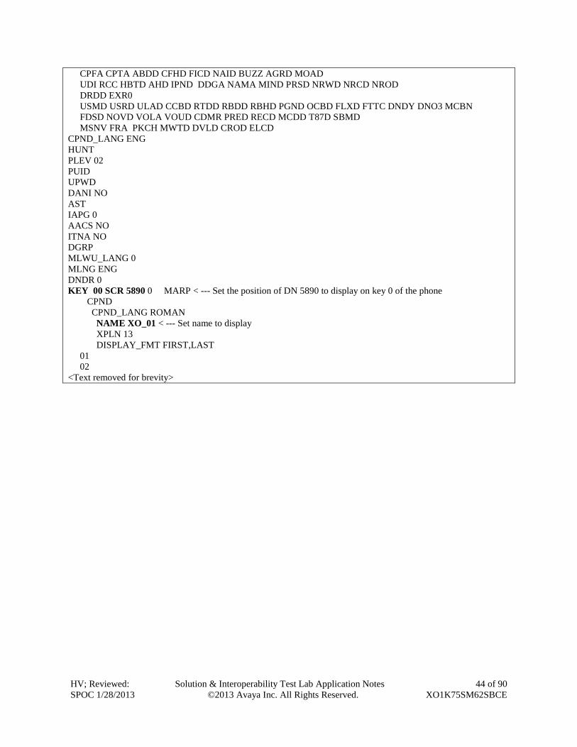
KEY 00 SCR 5890 0 MARP < --- Set the position of DN 5890 to display on key 0 of the phone
CPND
CPND_LANG ROMAN
NAME XO_01 < --- Set name to display
XPLN 13
DISPLAY_FMT FIRST,LAST
01
02
<Text removed for brevity>
HV; Reviewed:
SPOC 1/28/2013
Solution & Interoperability Test Lab Application Notes
©2013 Avaya Inc. All Rights Reserved.
45 of 90
XO1K75SM62SBCE
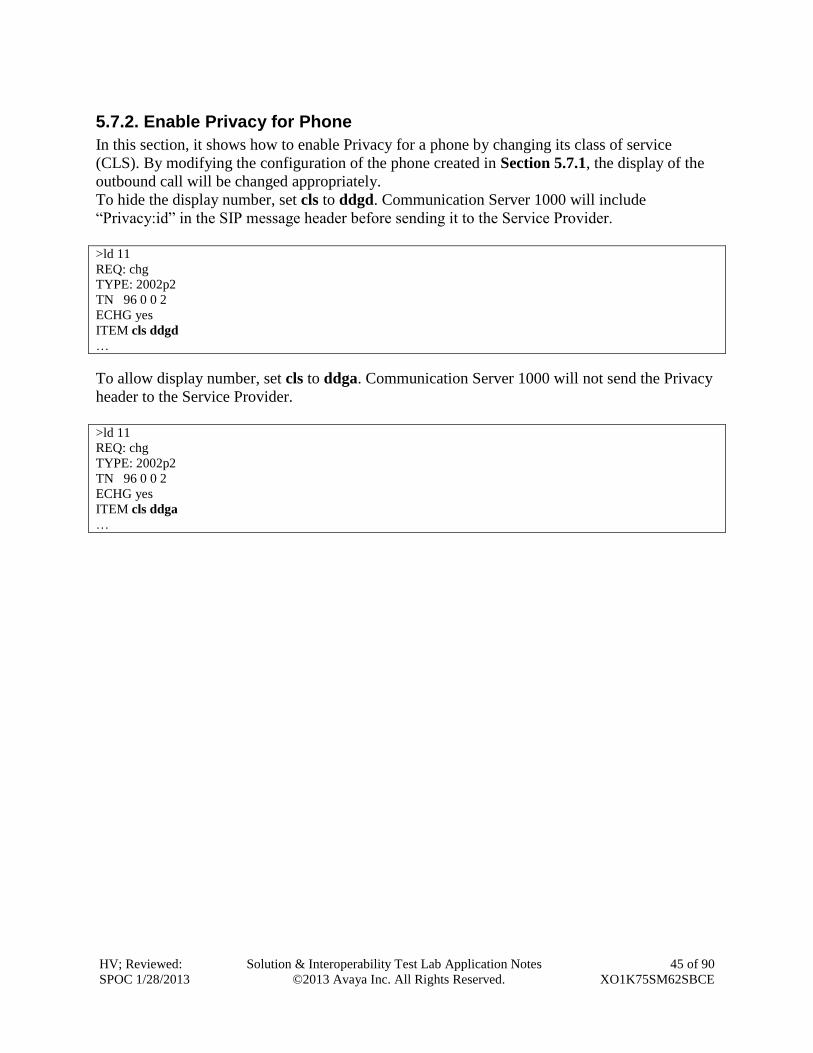
5.7.2. Enable Privacy for Phone
In this section, it shows how to enable Privacy for a phone by changing its class of service
(CLS). By modifying the configuration of the phone created in Section 5.7.1, the display of the
outbound call will be changed appropriately.
To hide the display number, set cls to ddgd. Communication Server 1000 will include
“Privacy:id” in the SIP message header before sending it to the Service Provider.
>ld 11
REQ: chg
TYPE: 2002p2
TN 96 0 0 2
ECHG yes
ITEM cls ddgd
…
To allow display number, set cls to ddga. Communication Server 1000 will not send the Privacy
header to the Service Provider.
>ld 11
REQ: chg
TYPE: 2002p2
TN 96 0 0 2
ECHG yes
ITEM cls ddga
…
HV; Reviewed:
SPOC 1/28/2013
Solution & Interoperability Test Lab Application Notes
©2013 Avaya Inc. All Rights Reserved.
46 of 90
XO1K75SM62SBCE
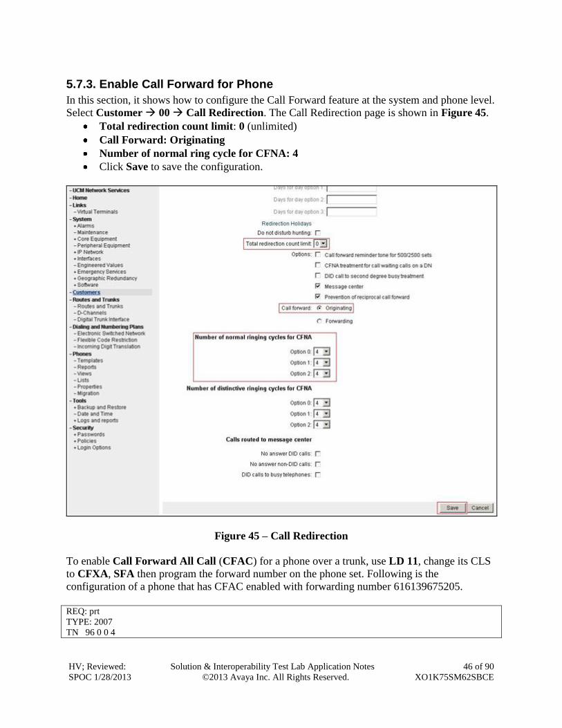
5.7.3. Enable Call Forward for Phone
In this section, it shows how to configure the Call Forward feature at the system and phone level.
Select Customer 00 Call Redirection. The Call Redirection page is shown in Figure 45.
Total redirection count limit: 0 (unlimited)
Call Forward: Originating
Number of normal ring cycle for CFNA: 4
Click Save to save the configuration.
Figure 45 – Call Redirection
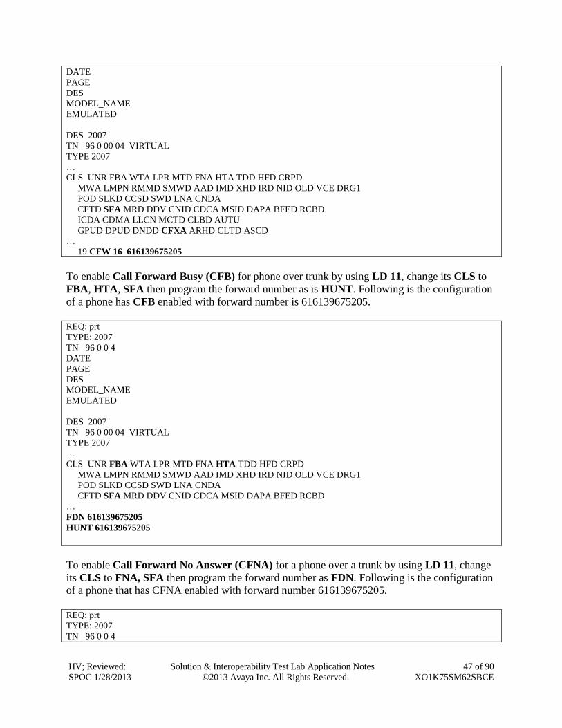
To enable Call Forward All Call (CFAC) for a phone over a trunk, use LD 11, change its CLS
to CFXA, SFA then program the forward number on the phone set. Following is the
configuration of a phone that has CFAC enabled with forwarding number 616139675205.
REQ: prt
TYPE: 2007
TN 96 0 0 4
HV; Reviewed:
SPOC 1/28/2013
Solution & Interoperability Test Lab Application Notes
©2013 Avaya Inc. All Rights Reserved.
47 of 90
XO1K75SM62SBCE
DATE
PAGE
DES
MODEL_NAME
EMULATED
DES 2007
TN 96 0 00 04 VIRTUAL
TYPE 2007
…
CLS UNR FBA WTA LPR MTD FNA HTA TDD HFD CRPD
MWA LMPN RMMD SMWD AAD IMD XHD IRD NID OLD VCE DRG1
POD SLKD CCSD SWD LNA CNDA
CFTD SFA MRD DDV CNID CDCA MSID DAPA BFED RCBD
ICDA CDMA LLCN MCTD CLBD AUTU
GPUD DPUD DNDD CFXA ARHD CLTD ASCD
…
19 CFW 16 616139675205
To enable Call Forward Busy (CFB) for phone over trunk by using LD 11, change its CLS to
FBA, HTA, SFA then program the forward number as is HUNT. Following is the configuration
of a phone has CFB enabled with forward number is 616139675205.
REQ: prt
TYPE: 2007
TN 96 0 0 4
DATE
PAGE
DES
MODEL_NAME
EMULATED
DES 2007
TN 96 0 00 04 VIRTUAL
TYPE 2007
…
CLS UNR FBA WTA LPR MTD FNA HTA TDD HFD CRPD
MWA LMPN RMMD SMWD AAD IMD XHD IRD NID OLD VCE DRG1
POD SLKD CCSD SWD LNA CNDA
CFTD SFA MRD DDV CNID CDCA MSID DAPA BFED RCBD
…
FDN 616139675205
HUNT 616139675205
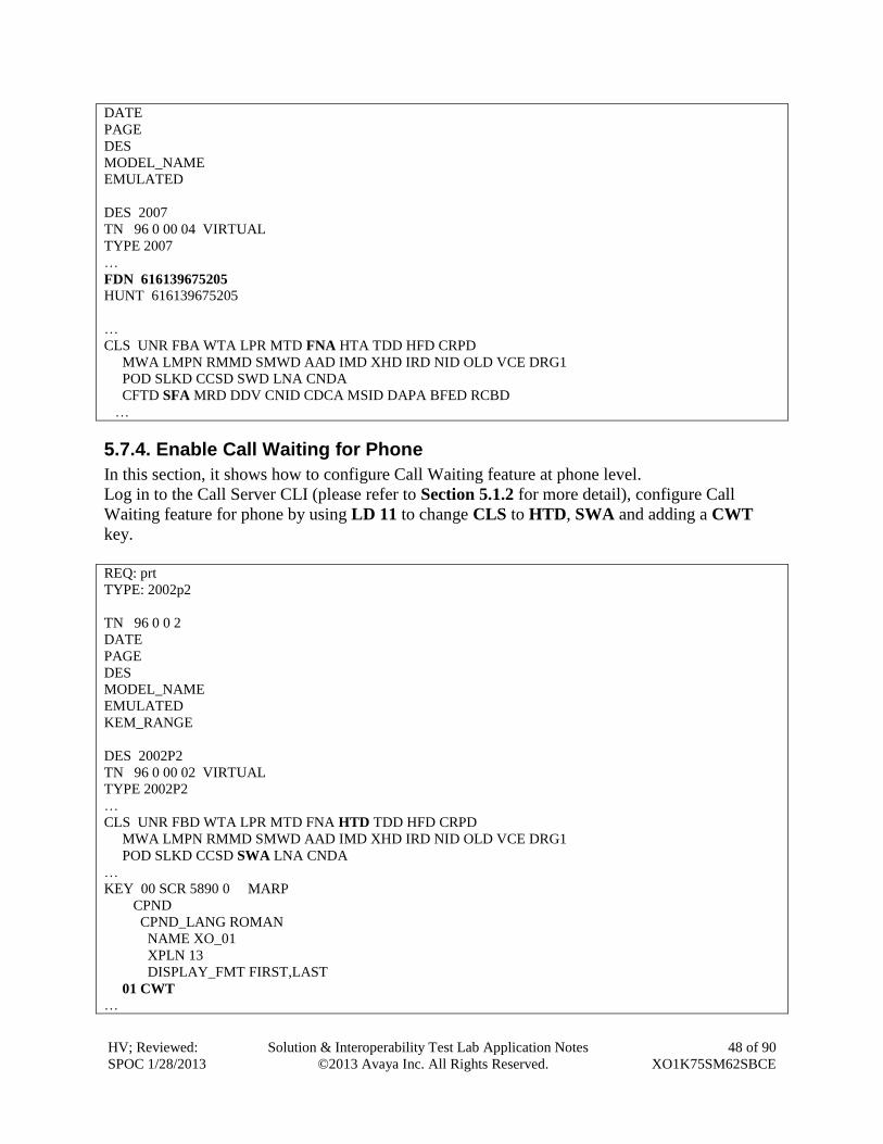
To enable Call Forward No Answer (CFNA) for a phone over a trunk by using LD 11, change
its CLS to FNA, SFA then program the forward number as FDN. Following is the configuration
of a phone that has CFNA enabled with forward number 616139675205.
REQ: prt
TYPE: 2007
TN 96 0 0 4
HV; Reviewed:
SPOC 1/28/2013
Solution & Interoperability Test Lab Application Notes
©2013 Avaya Inc. All Rights Reserved.
48 of 90
XO1K75SM62SBCE
DATE
PAGE
DES
MODEL_NAME
EMULATED
DES 2007
TN 96 0 00 04 VIRTUAL
TYPE 2007
…
FDN 616139675205
HUNT 616139675205
…
CLS UNR FBA WTA LPR MTD FNA HTA TDD HFD CRPD
MWA LMPN RMMD SMWD AAD IMD XHD IRD NID OLD VCE DRG1
POD SLKD CCSD SWD LNA CNDA
CFTD SFA MRD DDV CNID CDCA MSID DAPA BFED RCBD
…
5.7.4. Enable Call Waiting for Phone
In this section, it shows how to configure Call Waiting feature at phone level.
Log in to the Call Server CLI (please refer to Section 5.1.2 for more detail), configure Call
Waiting feature for phone by using LD 11 to change CLS to HTD, SWA and adding a CWT
key.
REQ: prt
TYPE: 2002p2
TN 96 0 0 2
DATE
PAGE
DES
MODEL_NAME
EMULATED
KEM_RANGE
DES 2002P2
TN 96 0 00 02 VIRTUAL
TYPE 2002P2
…
CLS UNR FBD WTA LPR MTD FNA HTD TDD HFD CRPD
MWA LMPN RMMD SMWD AAD IMD XHD IRD NID OLD VCE DRG1
POD SLKD CCSD SWA LNA CNDA
…
KEY 00 SCR 5890 0 MARP
CPND
CPND_LANG ROMAN
NAME XO_01
XPLN 13
DISPLAY_FMT FIRST,LAST
01 CWT
…
HV; Reviewed:
SPOC 1/28/2013
Solution & Interoperability Test Lab Application Notes
©2013 Avaya Inc. All Rights Reserved.
49 of 90
XO1K75SM62SBCE
6. Configure Avaya Aura® Session Manager This section provides the procedures for configuring Session Manager. The procedures include
configuring the following items:
SIP Domain.
Logical/physical Location that can be occupied by SIP Entities.
Adaptation module to perform dial plan manipulation.
SIP Entities corresponding to Communication Server 1000, SBCE and Session Manager.
Entity Links, which define the SIP trunk parameters used by Session Manager when
routing calls to/from SIP Entities.
Routing Policies, which define route destinations and control call routing between the SIP
Entities.
Dial Patterns, which specify dialed digits and govern which Routing Policy is used to
service a call.
It may not be necessary to create all the items above when configuring a connection to the
service provider since some of these items would have already been defined as part of the initial
Session Manager installation. This includes items such as certain SIP Domains, Locations, SIP
Entities, and Session Manager itself. However, each item should be reviewed to verify the
configuration.
HV; Reviewed:
SPOC 1/28/2013
Solution & Interoperability Test Lab Application Notes
©2013 Avaya Inc. All Rights Reserved.
50 of 90
XO1K75SM62SBCE
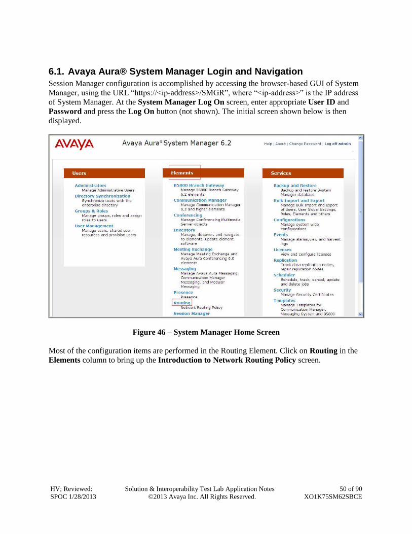
6.1. Avaya Aura® System Manager Login and Navigation
Session Manager configuration is accomplished by accessing the browser-based GUI of System
Manager, using the URL “https://<ip-address>/SMGR”, where “<ip-address>” is the IP address
of System Manager. At the System Manager Log On screen, enter appropriate User ID and
Password and press the Log On button (not shown). The initial screen shown below is then
displayed.
Figure 46 – System Manager Home Screen
Most of the configuration items are performed in the Routing Element. Click on Routing in the
Elements column to bring up the Introduction to Network Routing Policy screen.
HV; Reviewed:
SPOC 1/28/2013
Solution & Interoperability Test Lab Application Notes
©2013 Avaya Inc. All Rights Reserved.
51 of 90
XO1K75SM62SBCE
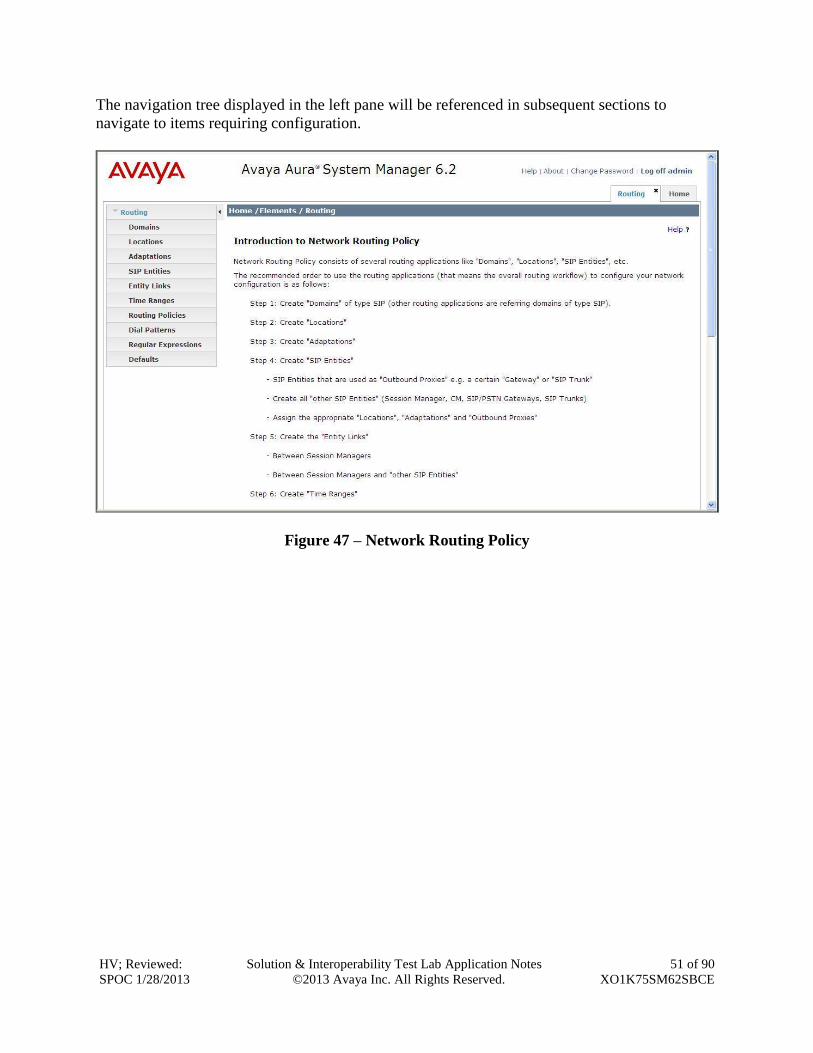
The navigation tree displayed in the left pane will be referenced in subsequent sections to
navigate to items requiring configuration.
Figure 47 – Network Routing Policy
HV; Reviewed:
SPOC 1/28/2013
Solution & Interoperability Test Lab Application Notes
©2013 Avaya Inc. All Rights Reserved.
52 of 90
XO1K75SM62SBCE
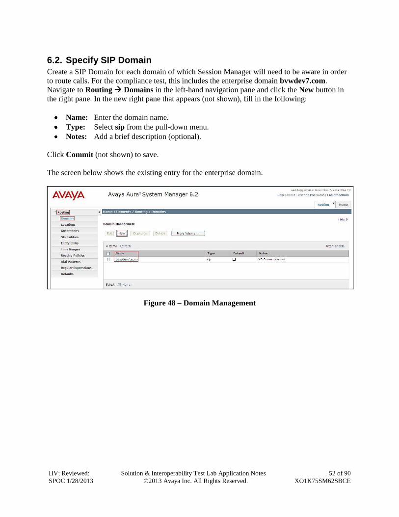
6.2. Specify SIP Domain
Create a SIP Domain for each domain of which Session Manager will need to be aware in order
to route calls. For the compliance test, this includes the enterprise domain bvwdev7.com.
Navigate to Routing Domains in the left-hand navigation pane and click the New button in
the right pane. In the new right pane that appears (not shown), fill in the following:
Name: Enter the domain name.
Type: Select sip from the pull-down menu.
Notes: Add a brief description (optional).
Click Commit (not shown) to save.
The screen below shows the existing entry for the enterprise domain.
Figure 48 – Domain Management
HV; Reviewed:
SPOC 1/28/2013
Solution & Interoperability Test Lab Application Notes
©2013 Avaya Inc. All Rights Reserved.
53 of 90
XO1K75SM62SBCE
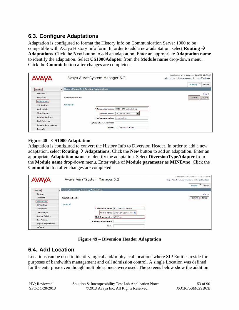
6.3. Configure Adaptations
Adaptation is configured to format the History Info on Communication Server 1000 to be
compatible with Avaya History Info form. In order to add a new adaptation, select Routing
Adaptations. Click the New button to add an adaptation. Enter an appropriate Adaptation name
to identify the adaptation. Select CS1000Adapter from the Module name drop-down menu.
Click the Commit button after changes are completed.
Figure 48 - CS1000 Adaptation Adaptation is configured to convert the History Info to Diversion Header. In order to add a new
adaptation, select Routing Adaptations. Click the New button to add an adaptation. Enter an
appropriate Adaptation name to identify the adaptation. Select DiversionTypeAdapter from
the Module name drop-down menu. Enter value of Module parameter as MINE=no. Click the
Commit button after changes are completed.
Figure 49 – Diversion Header Adaptation
6.4. Add Location
Locations can be used to identify logical and/or physical locations where SIP Entities reside for
purposes of bandwidth management and call admission control. A single Location was defined
for the enterprise even though multiple subnets were used. The screens below show the addition

HV; Reviewed:
SPOC 1/28/2013
Solution & Interoperability Test Lab Application Notes
©2013 Avaya Inc. All Rights Reserved.
54 of 90
XO1K75SM62SBCE
of the Location named Belleville, which includes all equipment in the enterprise including
Communication Server 1000, Session Manager and SBCE.
To add a Location, navigate to Routing Locations in the left-hand navigation pane and click
the New button in the right pane (not shown). In the new right pane that appears (shown below),
fill in the following:
In the General section, enter the following values. Use default values for all remaining fields.
Name: Enter a descriptive name for the Location.
Notes: Add a brief description (optional).
Figure 50 – Location Configuration
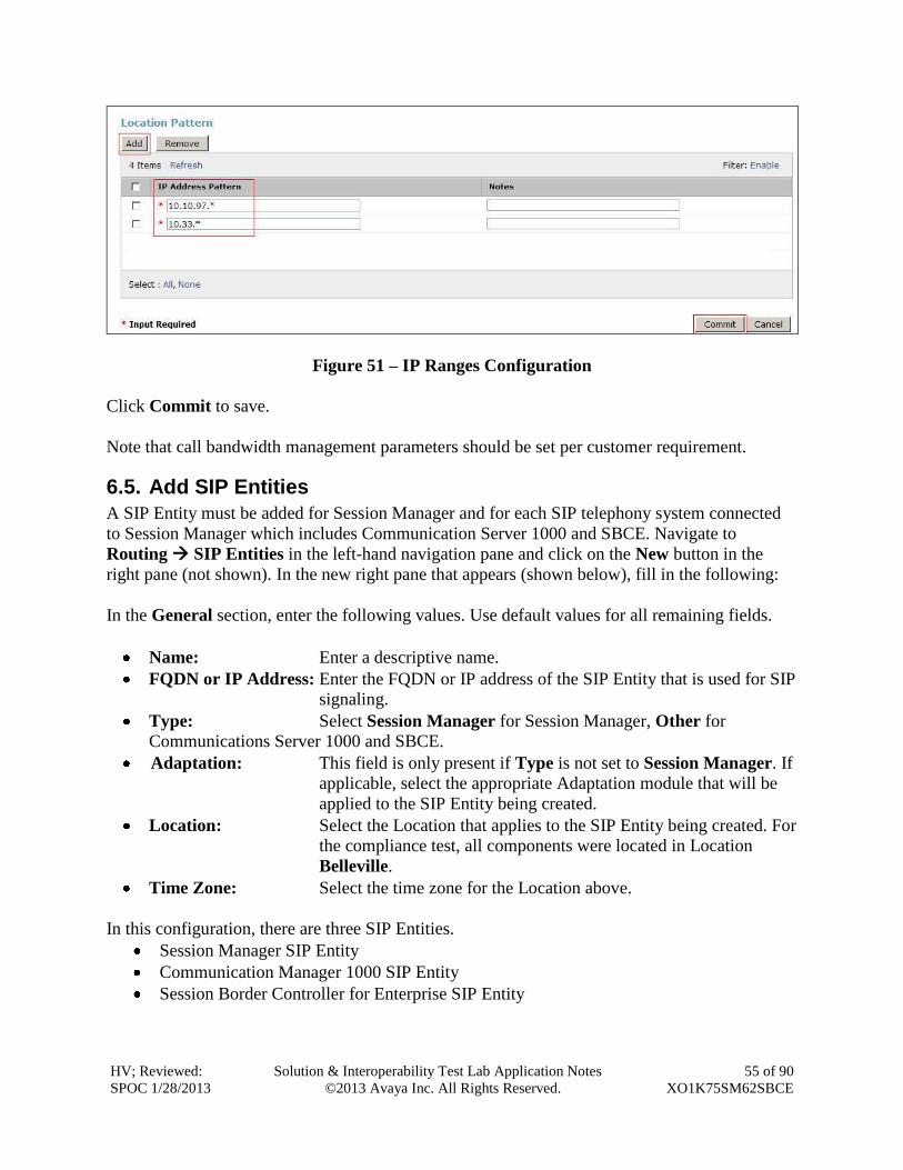
In the Location Pattern section, Click Add to enter IP Address pattern as the following values.
IP Address Pattern: 10.10.97.*, 10.33.*.
HV; Reviewed:
SPOC 1/28/2013
Solution & Interoperability Test Lab Application Notes
©2013 Avaya Inc. All Rights Reserved.
55 of 90
XO1K75SM62SBCE
Figure 51 – IP Ranges Configuration
Click Commit to save.
Note that call bandwidth management parameters should be set per customer requirement.
6.5. Add SIP Entities
A SIP Entity must be added for Session Manager and for each SIP telephony system connected
to Session Manager which includes Communication Server 1000 and SBCE. Navigate to
Routing SIP Entities in the left-hand navigation pane and click on the New button in the
right pane (not shown). In the new right pane that appears (shown below), fill in the following:
In the General section, enter the following values. Use default values for all remaining fields.
Name: Enter a descriptive name.
FQDN or IP Address: Enter the FQDN or IP address of the SIP Entity that is used for SIP
signaling.
Type: Select Session Manager for Session Manager, Other for
Communications Server 1000 and SBCE.
Adaptation: This field is only present if Type is not set to Session Manager. If
applicable, select the appropriate Adaptation module that will be
applied to the SIP Entity being created.
Location: Select the Location that applies to the SIP Entity being created. For
the compliance test, all components were located in Location
Belleville.
Time Zone: Select the time zone for the Location above.
In this configuration, there are three SIP Entities.
Session Manager SIP Entity
Communication Manager 1000 SIP Entity
Session Border Controller for Enterprise SIP Entity
HV; Reviewed:
SPOC 1/28/2013
Solution & Interoperability Test Lab Application Notes
©2013 Avaya Inc. All Rights Reserved.
56 of 90
XO1K75SM62SBCE
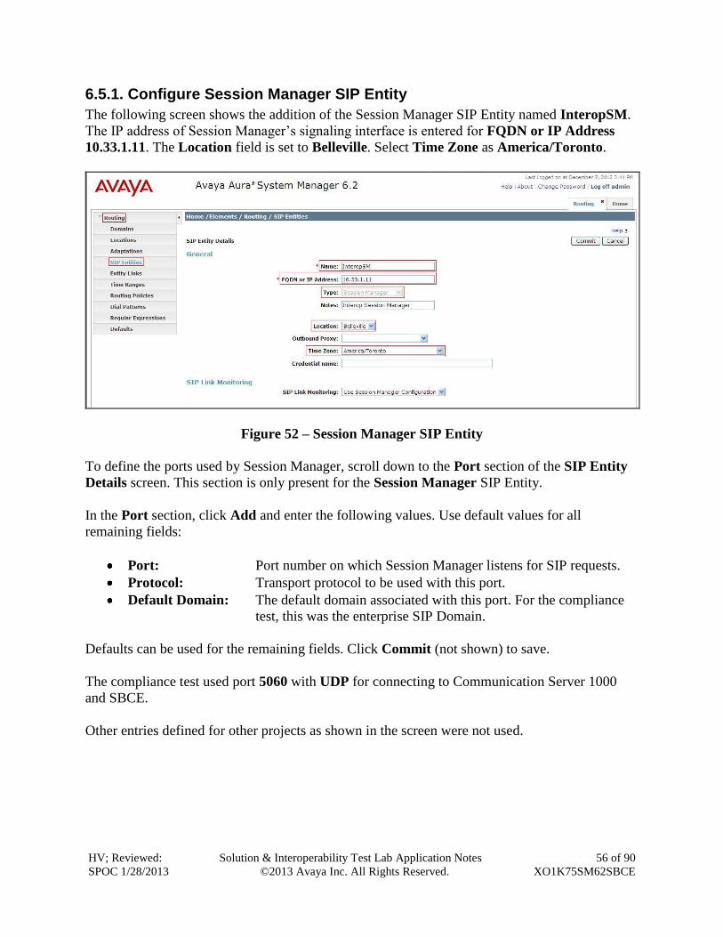
6.5.1. Configure Session Manager SIP Entity
The following screen shows the addition of the Session Manager SIP Entity named InteropSM.
The IP address of Session Manager’s signaling interface is entered for FQDN or IP Address
10.33.1.11. The Location field is set to Belleville. Select Time Zone as America/Toronto.
Figure 52 – Session Manager SIP Entity
To define the ports used by Session Manager, scroll down to the Port section of the SIP Entity
Details screen. This section is only present for the Session Manager SIP Entity.
In the Port section, click Add and enter the following values. Use default values for all
remaining fields:
Port: Port number on which Session Manager listens for SIP requests.
Protocol: Transport protocol to be used with this port.
Default Domain: The default domain associated with this port. For the compliance
test, this was the enterprise SIP Domain.
Defaults can be used for the remaining fields. Click Commit (not shown) to save.
The compliance test used port 5060 with UDP for connecting to Communication Server 1000
and SBCE.
Other entries defined for other projects as shown in the screen were not used.
HV; Reviewed:
SPOC 1/28/2013
Solution & Interoperability Test Lab Application Notes
©2013 Avaya Inc. All Rights Reserved.
57 of 90
XO1K75SM62SBCE
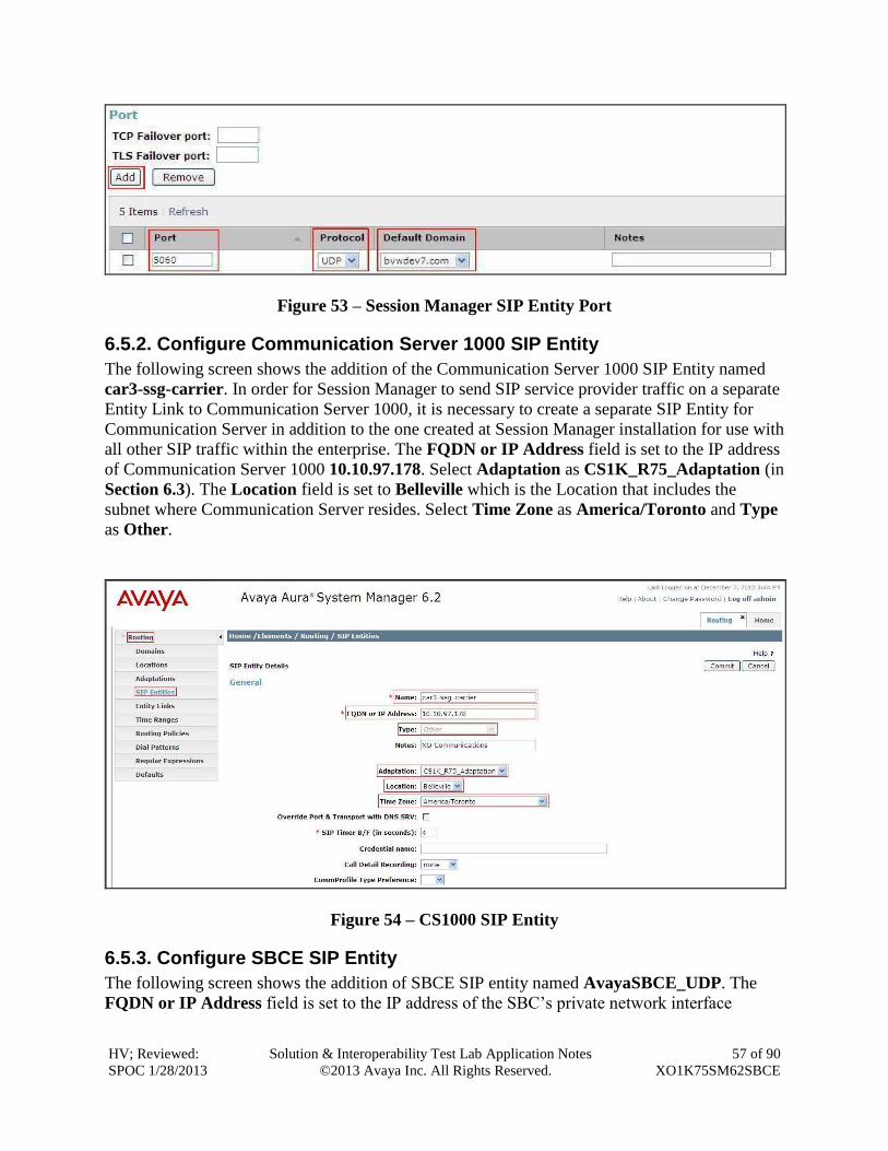
Figure 53 – Session Manager SIP Entity Port
6.5.2. Configure Communication Server 1000 SIP Entity
The following screen shows the addition of the Communication Server 1000 SIP Entity named
car3-ssg-carrier. In order for Session Manager to send SIP service provider traffic on a separate
Entity Link to Communication Server 1000, it is necessary to create a separate SIP Entity for
Communication Server in addition to the one created at Session Manager installation for use with
all other SIP traffic within the enterprise. The FQDN or IP Address field is set to the IP address
of Communication Server 1000 10.10.97.178. Select Adaptation as CS1K_R75_Adaptation (in
Section 6.3). The Location field is set to Belleville which is the Location that includes the
subnet where Communication Server resides. Select Time Zone as America/Toronto and Type
as Other.
Figure 54 – CS1000 SIP Entity
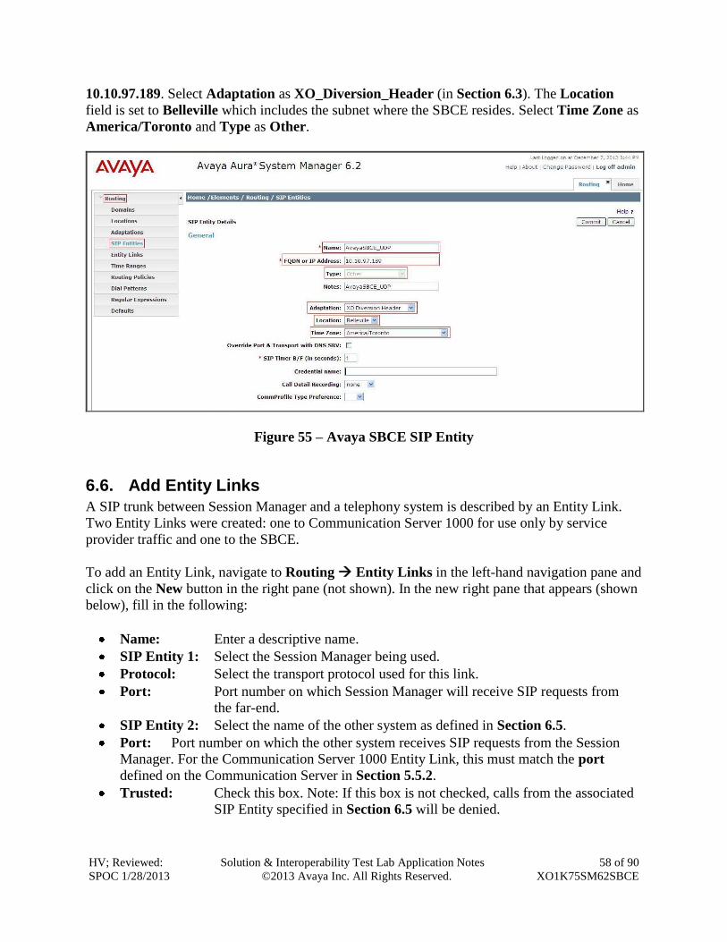
6.5.3. Configure SBCE SIP Entity
The following screen shows the addition of SBCE SIP entity named AvayaSBCE_UDP. The
FQDN or IP Address field is set to the IP address of the SBC’s private network interface
HV; Reviewed:
SPOC 1/28/2013
Solution & Interoperability Test Lab Application Notes
©2013 Avaya Inc. All Rights Reserved.
58 of 90
XO1K75SM62SBCE
10.10.97.189. Select Adaptation as XO_Diversion_Header (in Section 6.3). The Location
field is set to Belleville which includes the subnet where the SBCE resides. Select Time Zone as
America/Toronto and Type as Other.
Figure 55 – Avaya SBCE SIP Entity
6.6. Add Entity Links
A SIP trunk between Session Manager and a telephony system is described by an Entity Link.
Two Entity Links were created: one to Communication Server 1000 for use only by service
provider traffic and one to the SBCE.
To add an Entity Link, navigate to Routing Entity Links in the left-hand navigation pane and
click on the New button in the right pane (not shown). In the new right pane that appears (shown
below), fill in the following:
Name: Enter a descriptive name.
SIP Entity 1: Select the Session Manager being used.
Protocol: Select the transport protocol used for this link.
Port: Port number on which Session Manager will receive SIP requests from
the far-end.
SIP Entity 2: Select the name of the other system as defined in Section 6.5.
Port: Port number on which the other system receives SIP requests from the Session
Manager. For the Communication Server 1000 Entity Link, this must match the port
defined on the Communication Server in Section 5.5.2.
Trusted: Check this box. Note: If this box is not checked, calls from the associated
SIP Entity specified in Section 6.5 will be denied.
HV; Reviewed:
SPOC 1/28/2013
Solution & Interoperability Test Lab Application Notes
©2013 Avaya Inc. All Rights Reserved.
59 of 90
XO1K75SM62SBCE
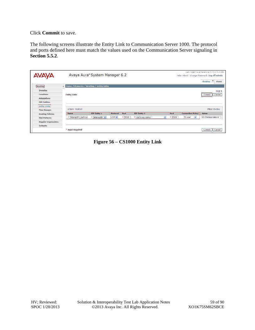
Click Commit to save.
The following screens illustrate the Entity Link to Communication Server 1000. The protocol
and ports defined here must match the values used on the Communication Server signaling in
Section 5.5.2.
Figure 56 – CS1000 Entity Link
HV; Reviewed:
SPOC 1/28/2013
Solution & Interoperability Test Lab Application Notes
©2013 Avaya Inc. All Rights Reserved.
60 of 90
XO1K75SM62SBCE
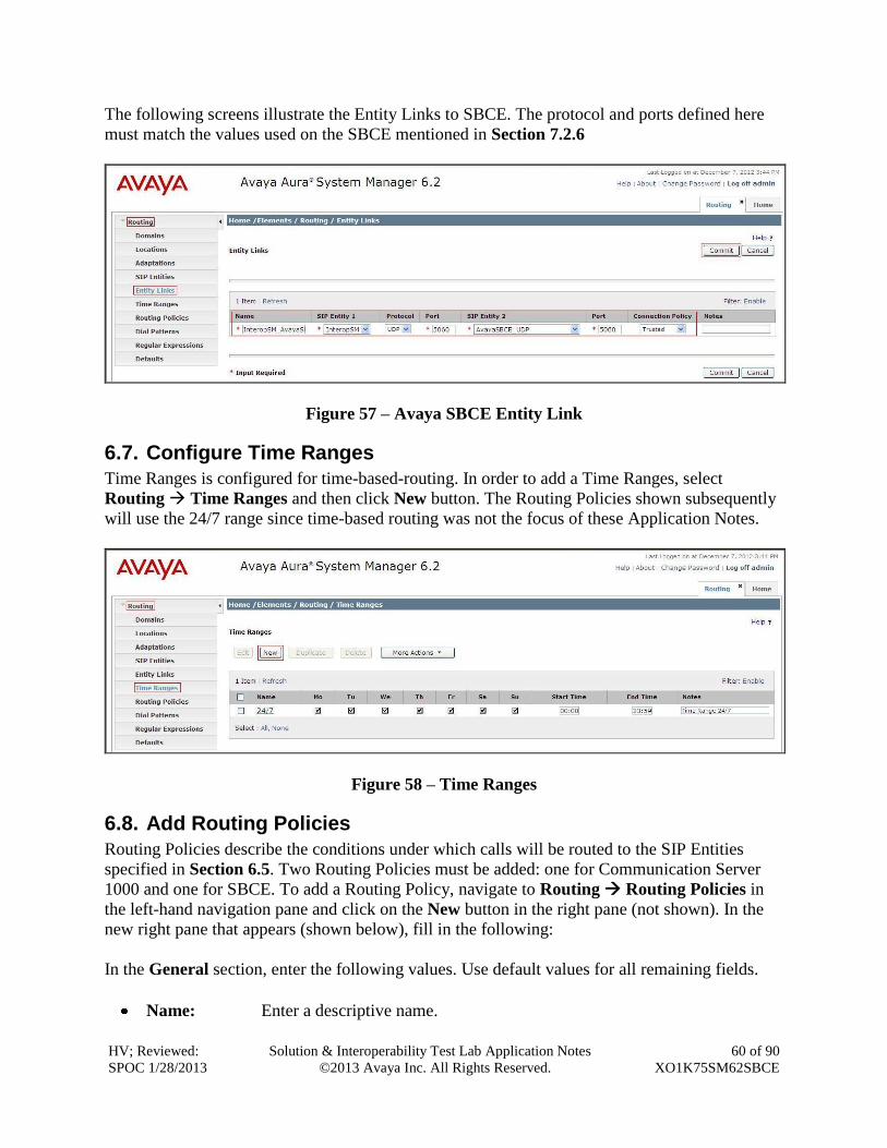
The following screens illustrate the Entity Links to SBCE. The protocol and ports defined here
must match the values used on the SBCE mentioned in Section 7.2.6
Figure 57 – Avaya SBCE Entity Link
6.7. Configure Time Ranges
Time Ranges is configured for time-based-routing. In order to add a Time Ranges, select
Routing Time Ranges and then click New button. The Routing Policies shown subsequently
will use the 24/7 range since time-based routing was not the focus of these Application Notes.
Figure 58 – Time Ranges
6.8. Add Routing Policies
Routing Policies describe the conditions under which calls will be routed to the SIP Entities
specified in Section 6.5. Two Routing Policies must be added: one for Communication Server
1000 and one for SBCE. To add a Routing Policy, navigate to Routing Routing Policies in
the left-hand navigation pane and click on the New button in the right pane (not shown). In the
new right pane that appears (shown below), fill in the following:
In the General section, enter the following values. Use default values for all remaining fields.
Name: Enter a descriptive name.
HV; Reviewed:
SPOC 1/28/2013
Solution & Interoperability Test Lab Application Notes
©2013 Avaya Inc. All Rights Reserved.
61 of 90
XO1K75SM62SBCE
Notes: Add a brief description (optional).
In the SIP Entity as Destination section, click Select. The SIP Entity List page opens (not
shown). Select the appropriate SIP Entity to which this Routing Policy applies and click Select.
The selected SIP Entity displays on the Routing Policy Details page as shown below. Use
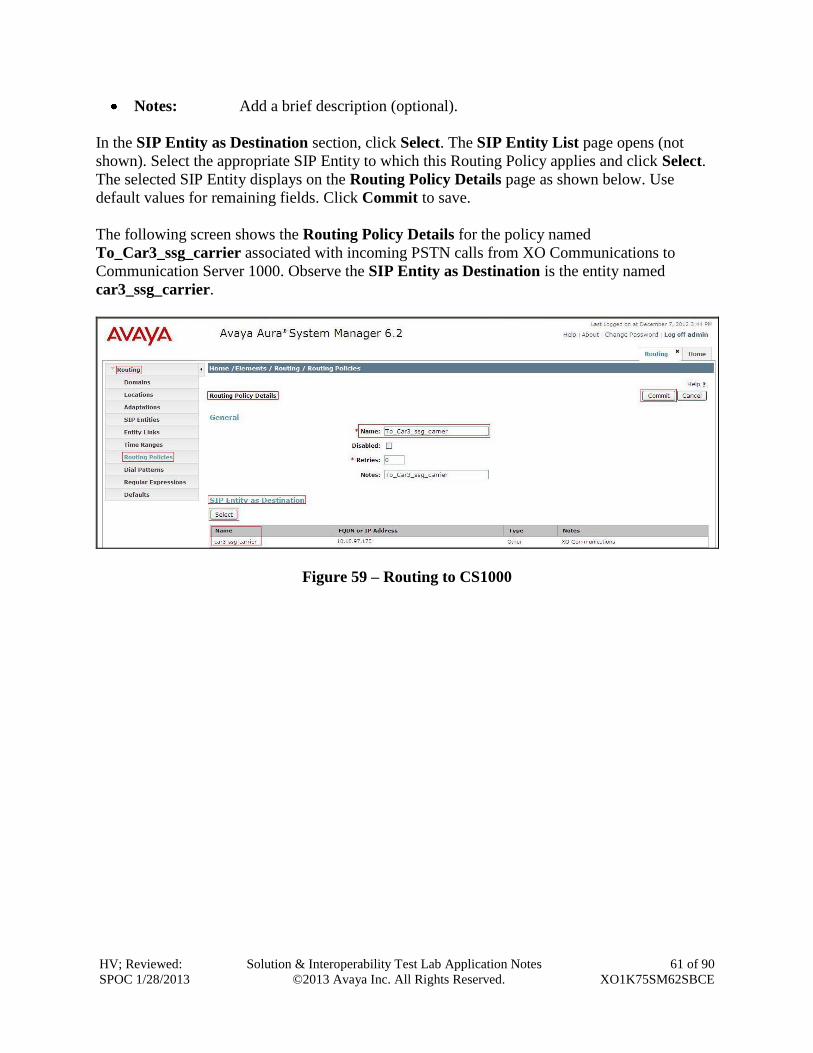
default values for remaining fields. Click Commit to save.
The following screen shows the Routing Policy Details for the policy named
To_Car3_ssg_carrier associated with incoming PSTN calls from XO Communications to
Communication Server 1000. Observe the SIP Entity as Destination is the entity named
car3_ssg_carrier.
Figure 59 – Routing to CS1000
HV; Reviewed:
SPOC 1/28/2013
Solution & Interoperability Test Lab Application Notes
©2013 Avaya Inc. All Rights Reserved.
62 of 90
XO1K75SM62SBCE
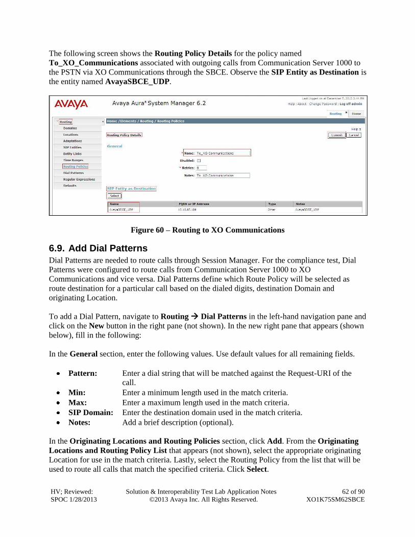
The following screen shows the Routing Policy Details for the policy named
To_XO_Communications associated with outgoing calls from Communication Server 1000 to
the PSTN via XO Communications through the SBCE. Observe the SIP Entity as Destination is
the entity named AvayaSBCE_UDP.
Figure 60 – Routing to XO Communications
6.9. Add Dial Patterns
Dial Patterns are needed to route calls through Session Manager. For the compliance test, Dial
Patterns were configured to route calls from Communication Server 1000 to XO
Communications and vice versa. Dial Patterns define which Route Policy will be selected as
route destination for a particular call based on the dialed digits, destination Domain and
originating Location.
To add a Dial Pattern, navigate to Routing Dial Patterns in the left-hand navigation pane and
click on the New button in the right pane (not shown). In the new right pane that appears (shown
below), fill in the following:
In the General section, enter the following values. Use default values for all remaining fields.
Pattern: Enter a dial string that will be matched against the Request-URI of the
call.
Min: Enter a minimum length used in the match criteria.
Max: Enter a maximum length used in the match criteria.
SIP Domain: Enter the destination domain used in the match criteria.
Notes: Add a brief description (optional).
In the Originating Locations and Routing Policies section, click Add. From the Originating
Locations and Routing Policy List that appears (not shown), select the appropriate originating
Location for use in the match criteria. Lastly, select the Routing Policy from the list that will be
used to route all calls that match the specified criteria. Click Select.
HV; Reviewed:
SPOC 1/28/2013
Solution & Interoperability Test Lab Application Notes
©2013 Avaya Inc. All Rights Reserved.
63 of 90
XO1K75SM62SBCE
Default values can be used for the remaining fields. Click Commit to save.
Two examples of the Dial Patterns used for the compliance test are shown below, one for
outbound calls from the enterprise to the PSTN and one for inbound calls from the PSTN to the
enterprise. Other Dial Patterns (e.g., 1800 Toll free call, 011 international call, etc.) were
similarly defined.
The first example shows that outbound 11-digit dialed numbers that begin with 1613 and have a
destination SIP Domain of bvwdev7.com uses the AvayaSBCE_UDP Routing Policy as defined
in Section 6.8.
Figure 61 – Dial Pattern_1613
Note that the above Dial Pattern did not restrict outbound calls to specific US area codes. In real
deployments, appropriate restriction can be exercised per customer business policies.
The second example shows that inbound 10-digit numbers that start with 214 uses Routing
Policy car3_ssg_carrier as defined in Section 6.8. This Dial Pattern matches the DID numbers
assigned to the enterprise by XO Communications.
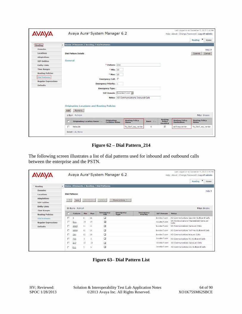
HV; Reviewed:
SPOC 1/28/2013
Solution & Interoperability Test Lab Application Notes
©2013 Avaya Inc. All Rights Reserved.
64 of 90
XO1K75SM62SBCE
Figure 62 – Dial Pattern_214
The following screen illustrates a list of dial patterns used for inbound and outbound calls
between the enterprise and the PSTN.
Figure 63– Dial Pattern List
HV; Reviewed:
SPOC 1/28/2013
Solution & Interoperability Test Lab Application Notes
©2013 Avaya Inc. All Rights Reserved.
65 of 90
XO1K75SM62SBCE
7. Configure Session Border Controller for Enterprise This section describes the configuration of the SBCE necessary for interoperability with the
Session Manager and XO Communications system.
In this testing, according to the configuration reference Figure 1, the Avaya elements reside on
the Private side and the XO Communications system reside on the Public side of the network.
Note: The following section assumes that SBCE has been installed and that network connectivity
exists between the systems. For more information on SBCE, see Section 11 of these Application
Notes.
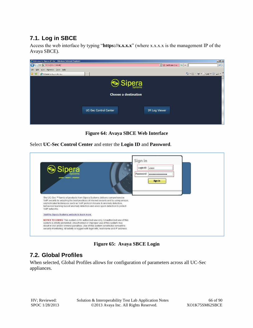
HV; Reviewed:
SPOC 1/28/2013
Solution & Interoperability Test Lab Application Notes
©2013 Avaya Inc. All Rights Reserved.
66 of 90
XO1K75SM62SBCE
7.1. Log in SBCE
Access the web interface by typing “https://x.x.x.x” (where x.x.x.x is the management IP of the
Avaya SBCE).
Figure 64: Avaya SBCE Web Interface
Select UC-Sec Control Center and enter the Login ID and Password.
Figure 65: Avaya SBCE Login
7.2. Global Profiles
When selected, Global Profiles allows for configuration of parameters across all UC-Sec
appliances.
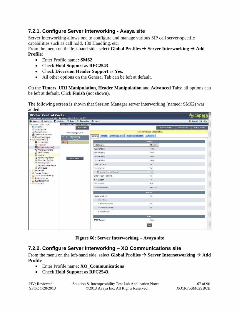
HV; Reviewed:
SPOC 1/28/2013
Solution & Interoperability Test Lab Application Notes
©2013 Avaya Inc. All Rights Reserved.
67 of 90
XO1K75SM62SBCE
7.2.1. Configure Server Interworking - Avaya site
Server Interworking allows one to configure and manage various SIP call server-specific
capabilities such as call hold, 180 Handling, etc.
From the menu on the left-hand side, select Global Profiles Server Interworking Add
Profile:
Enter Profile name: SM62
Check Hold Support as RFC2543
Check Diversion Header Support as Yes.
All other options on the General Tab can be left at default.
On the Timers, URI Manipulation, Header Manipulation and Advanced Tabs: all options can
be left at default. Click Finish (not shown).
The following screen is shown that Session Manager server interworking (named: SM62) was
added.
Figure 66: Server Interworking – Avaya site
7.2.2. Configure Server Interworking – XO Communications site
From the menu on the left-hand side, select Global Profiles Server Internetworking Add
Profile
Enter Profile name: XO_Communications
Check Hold Support as RFC2543.
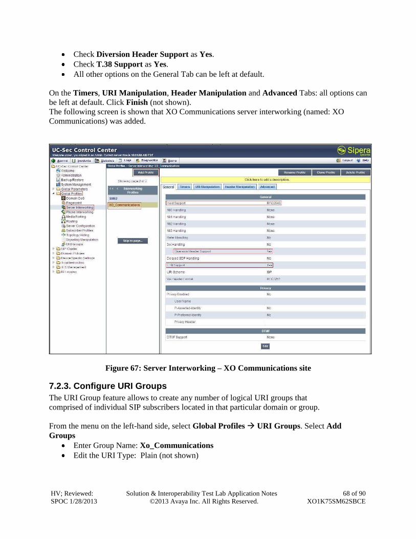
HV; Reviewed:
SPOC 1/28/2013
Solution & Interoperability Test Lab Application Notes
©2013 Avaya Inc. All Rights Reserved.
68 of 90
XO1K75SM62SBCE
Check Diversion Header Support as Yes.
Check T.38 Support as Yes.
All other options on the General Tab can be left at default.
On the Timers, URI Manipulation, Header Manipulation and Advanced Tabs: all options can
be left at default. Click Finish (not shown).
The following screen is shown that XO Communications server interworking (named: XO
Communications) was added.
Figure 67: Server Interworking – XO Communications site
7.2.3. Configure URI Groups
The URI Group feature allows to create any number of logical URI groups that
comprised of individual SIP subscribers located in that particular domain or group.
From the menu on the left-hand side, select Global Profiles URI Groups. Select Add
Groups
Enter Group Name: Xo_Communications
Edit the URI Type: Plain (not shown)
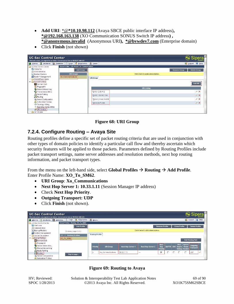
HV; Reviewed:
SPOC 1/28/2013
Solution & Interoperability Test Lab Application Notes
©2013 Avaya Inc. All Rights Reserved.
69 of 90
XO1K75SM62SBCE
Add URI: *@*10.10.98.112 (Avaya SBCE public interface IP address),
*@192.168.163.138 (XO Communication SONUS Switch IP address) ,
*@anonymous.invalid (Anonymous URI), *@bvwdev7.com (Enterprise domain)
Click Finish (not shown)
Figure 68: URI Group
7.2.4. Configure Routing – Avaya Site
Routing profiles define a specific set of packet routing criteria that are used in conjunction with
other types of domain policies to identify a particular call flow and thereby ascertain which
security features will be applied to those packets. Parameters defined by Routing Profiles include
packet transport settings, name server addresses and resolution methods, next hop routing
information, and packet transport types.
From the menu on the left-hand side, select Global Profiles Routing Add Profile.
Enter Profile Name: XO_To_SM62.
URI Group: Xo_Communications
Next Hop Server 1: 10.33.1.11 (Session Manager IP address)
Check Next Hop Priority.
Outgoing Transport: UDP
Click Finish (not shown).
Figure 69: Routing to Avaya
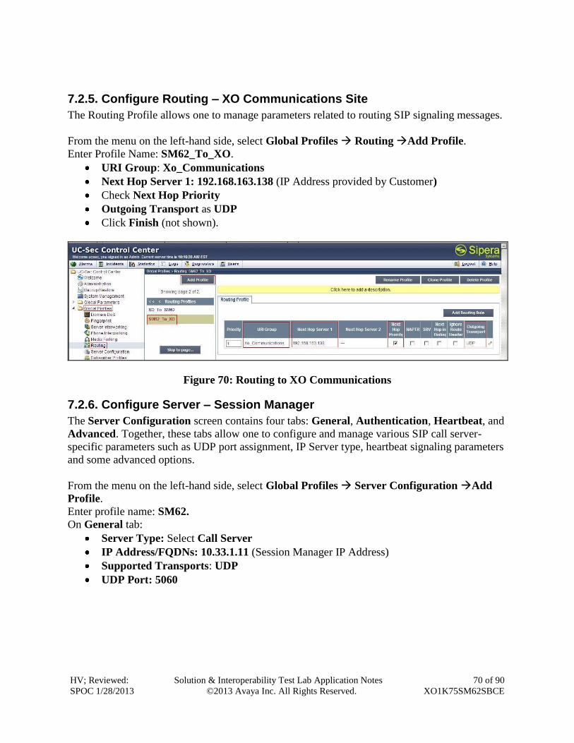
HV; Reviewed:
SPOC 1/28/2013
Solution & Interoperability Test Lab Application Notes
©2013 Avaya Inc. All Rights Reserved.
70 of 90
XO1K75SM62SBCE
7.2.5. Configure Routing – XO Communications Site
The Routing Profile allows one to manage parameters related to routing SIP signaling messages.
From the menu on the left-hand side, select Global Profiles Routing Add Profile.
Enter Profile Name: SM62_To_XO.
URI Group: Xo_Communications
Next Hop Server 1: 192.168.163.138 (IP Address provided by Customer)
Check Next Hop Priority
Outgoing Transport as UDP
Click Finish (not shown).
Figure 70: Routing to XO Communications
7.2.6. Configure Server – Session Manager
The Server Configuration screen contains four tabs: General, Authentication, Heartbeat, and
Advanced. Together, these tabs allow one to configure and manage various SIP call server-
specific parameters such as UDP port assignment, IP Server type, heartbeat signaling parameters
and some advanced options.
From the menu on the left-hand side, select Global Profiles Server Configuration Add
Profile.
Enter profile name: SM62.
On General tab:
Server Type: Select Call Server
IP Address/FQDNs: 10.33.1.11 (Session Manager IP Address)
Supported Transports: UDP
UDP Port: 5060
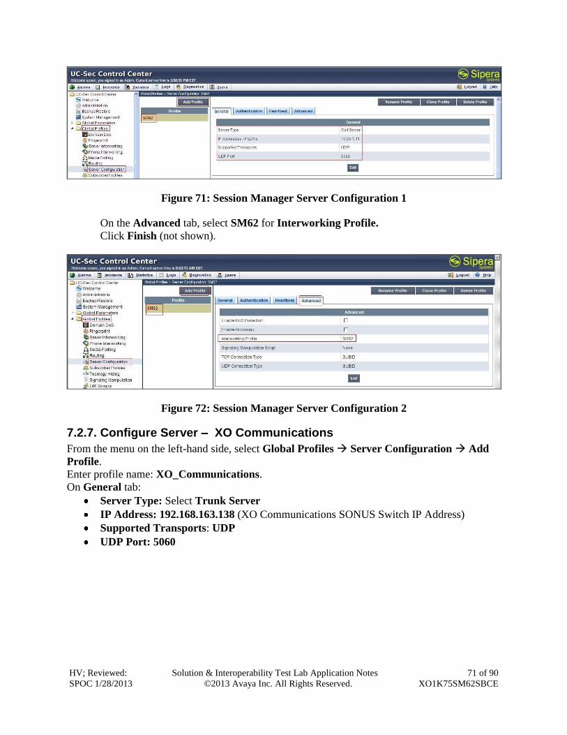
HV; Reviewed:
SPOC 1/28/2013
Solution & Interoperability Test Lab Application Notes
©2013 Avaya Inc. All Rights Reserved.
71 of 90
XO1K75SM62SBCE
Figure 71: Session Manager Server Configuration 1
On the Advanced tab, select SM62 for Interworking Profile.
Click Finish (not shown).
Figure 72: Session Manager Server Configuration 2
7.2.7. Configure Server – XO Communications
From the menu on the left-hand side, select Global Profiles Server Configuration Add
Profile.
Enter profile name: XO_Communications.
On General tab:
Server Type: Select Trunk Server
IP Address: 192.168.163.138 (XO Communications SONUS Switch IP Address)
Supported Transports: UDP
UDP Port: 5060
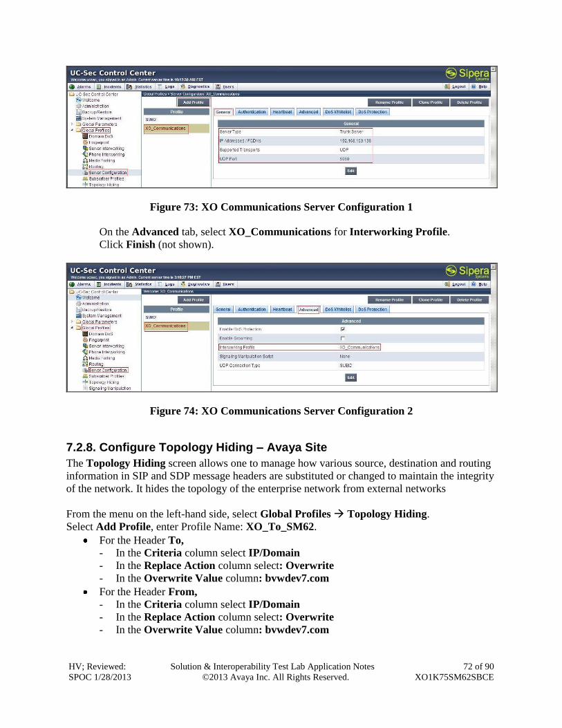
HV; Reviewed:
SPOC 1/28/2013
Solution & Interoperability Test Lab Application Notes
©2013 Avaya Inc. All Rights Reserved.
72 of 90
XO1K75SM62SBCE
Figure 73: XO Communications Server Configuration 1
On the Advanced tab, select XO_Communications for Interworking Profile.
Click Finish (not shown).
Figure 74: XO Communications Server Configuration 2
7.2.8. Configure Topology Hiding – Avaya Site
The Topology Hiding screen allows one to manage how various source, destination and routing
information in SIP and SDP message headers are substituted or changed to maintain the integrity
of the network. It hides the topology of the enterprise network from external networks
From the menu on the left-hand side, select Global Profiles Topology Hiding.
Select Add Profile, enter Profile Name: XO_To_SM62.
For the Header To,
- In the Criteria column select IP/Domain
- In the Replace Action column select: Overwrite
- In the Overwrite Value column: bvwdev7.com
For the Header From,
- In the Criteria column select IP/Domain
- In the Replace Action column select: Overwrite
- In the Overwrite Value column: bvwdev7.com
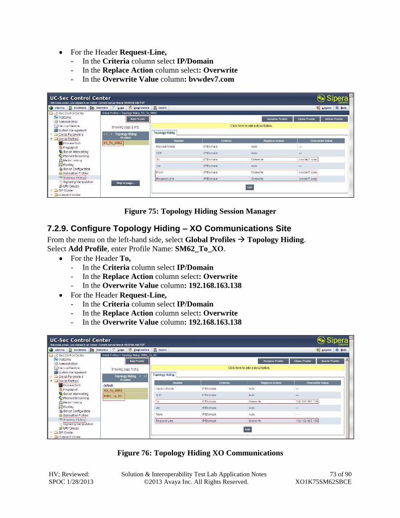
HV; Reviewed:
SPOC 1/28/2013
Solution & Interoperability Test Lab Application Notes
©2013 Avaya Inc. All Rights Reserved.
73 of 90
XO1K75SM62SBCE
For the Header Request-Line,
- In the Criteria column select IP/Domain
- In the Replace Action column select: Overwrite
- In the Overwrite Value column: bvwdev7.com
Figure 75: Topology Hiding Session Manager
7.2.9. Configure Topology Hiding – XO Communications Site
From the menu on the left-hand side, select Global Profiles Topology Hiding.
Select Add Profile, enter Profile Name: SM62_To_XO.
For the Header To,
- In the Criteria column select IP/Domain
- In the Replace Action column select: Overwrite
- In the Overwrite Value column: 192.168.163.138
For the Header Request-Line,
- In the Criteria column select IP/Domain
- In the Replace Action column select: Overwrite
- In the Overwrite Value column: 192.168.163.138
Figure 76: Topology Hiding XO Communications
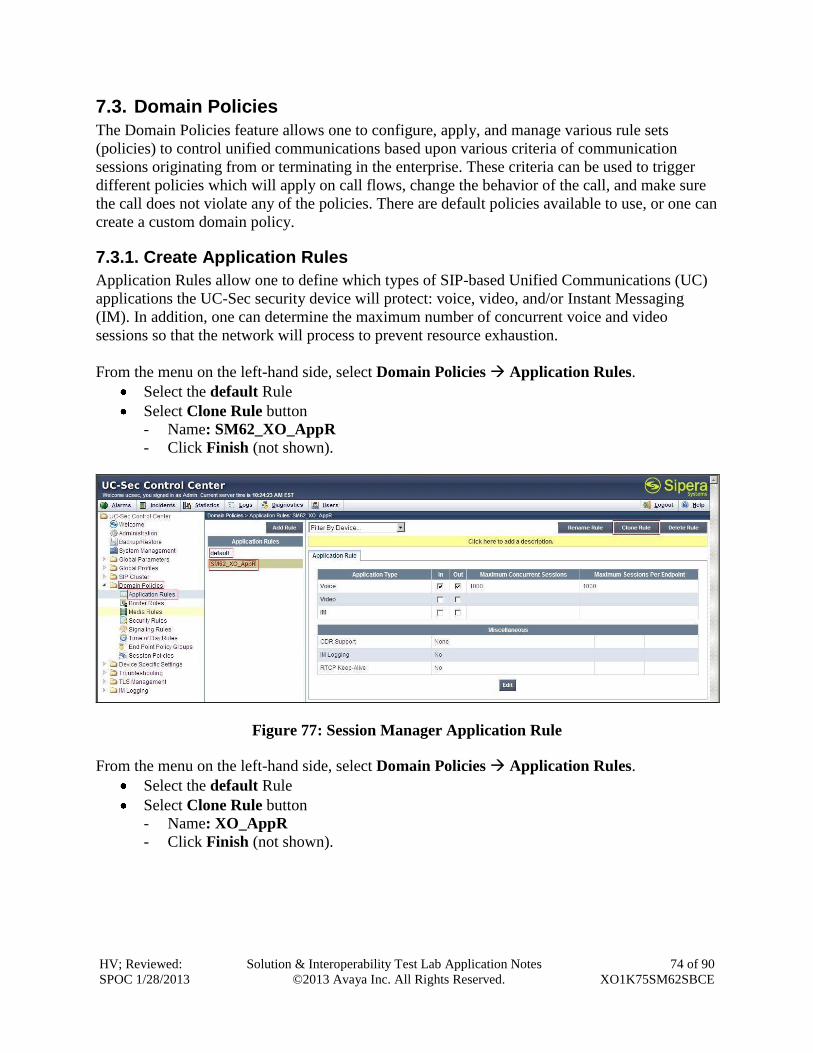
HV; Reviewed:
SPOC 1/28/2013
Solution & Interoperability Test Lab Application Notes
©2013 Avaya Inc. All Rights Reserved.
74 of 90
XO1K75SM62SBCE
7.3. Domain Policies
The Domain Policies feature allows one to configure, apply, and manage various rule sets
(policies) to control unified communications based upon various criteria of communication
sessions originating from or terminating in the enterprise. These criteria can be used to trigger
different policies which will apply on call flows, change the behavior of the call, and make sure
the call does not violate any of the policies. There are default policies available to use, or one can
create a custom domain policy.
7.3.1. Create Application Rules
Application Rules allow one to define which types of SIP-based Unified Communications (UC)
applications the UC-Sec security device will protect: voice, video, and/or Instant Messaging
(IM). In addition, one can determine the maximum number of concurrent voice and video
sessions so that the network will process to prevent resource exhaustion.
From the menu on the left-hand side, select Domain Policies Application Rules.
Select the default Rule
Select Clone Rule button
- Name: SM62_XO_AppR
- Click Finish (not shown).
Figure 77: Session Manager Application Rule
From the menu on the left-hand side, select Domain Policies Application Rules.
Select the default Rule
Select Clone Rule button
- Name: XO_AppR
- Click Finish (not shown).
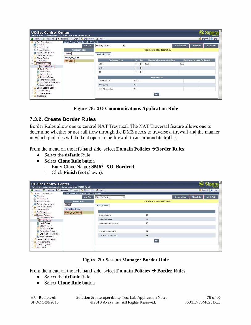
HV; Reviewed:
SPOC 1/28/2013
Solution & Interoperability Test Lab Application Notes
©2013 Avaya Inc. All Rights Reserved.
75 of 90
XO1K75SM62SBCE
Figure 78: XO Communications Application Rule
7.3.2. Create Border Rules
Border Rules allow one to control NAT Traversal. The NAT Traversal feature allows one to
determine whether or not call flow through the DMZ needs to traverse a firewall and the manner
in which pinholes will be kept open in the firewall to accommodate traffic.
From the menu on the left-hand side, select Domain Policies Border Rules.
Select the default Rule
Select Clone Rule button
- Enter Clone Name: SM62_XO_BorderR
- Click Finish (not shown).
Figure 79: Session Manager Border Rule
From the menu on the left-hand side, select Domain Policies Border Rules.
Select the default Rule
Select Clone Rule button
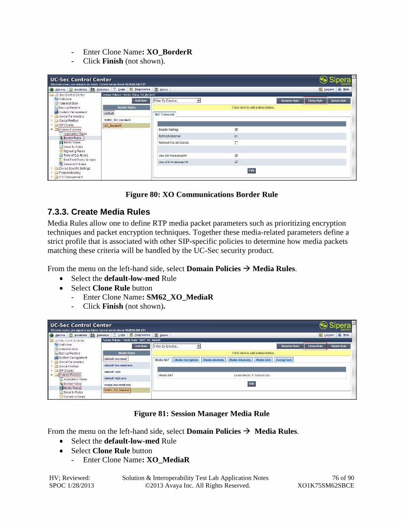
HV; Reviewed:
SPOC 1/28/2013
Solution & Interoperability Test Lab Application Notes
©2013 Avaya Inc. All Rights Reserved.
76 of 90
XO1K75SM62SBCE
- Enter Clone Name: XO_BorderR
- Click Finish (not shown).
Figure 80: XO Communications Border Rule
7.3.3. Create Media Rules
Media Rules allow one to define RTP media packet parameters such as prioritizing encryption
techniques and packet encryption techniques. Together these media-related parameters define a
strict profile that is associated with other SIP-specific policies to determine how media packets
matching these criteria will be handled by the UC-Sec security product.
From the menu on the left-hand side, select Domain Policies Media Rules.
Select the default-low-med Rule
Select Clone Rule button
- Enter Clone Name: SM62_XO_MediaR
- Click Finish (not shown).
Figure 81: Session Manager Media Rule
From the menu on the left-hand side, select Domain Policies Media Rules.
Select the default-low-med Rule
Select Clone Rule button
- Enter Clone Name: XO_MediaR
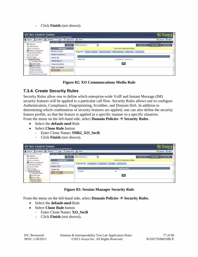
HV; Reviewed:
SPOC 1/28/2013
Solution & Interoperability Test Lab Application Notes
©2013 Avaya Inc. All Rights Reserved.
77 of 90
XO1K75SM62SBCE
- Click Finish (not shown).
Figure 82: XO Communcations Media Rule
7.3.4. Create Security Rules
Security Rules allow one to define which enterprise-wide VoIP and Instant Message (IM)
security features will be applied to a particular call flow. Security Rules allows one to configure
Authentication, Compliance, Fingerprinting, Scrubber, and Domain DoS. In addition to
determining which combination of security features are applied, one can also define the security
feature profile, so that the feature is applied in a specific manner to a specific situation.
From the menu on the left-hand side, select Domain Policies Security Rules.
Select the default-med Rule
Select Clone Rule button
- Enter Clone Name: SM62_XO_SecR
- Click Finish (not shown).
Figure 83: Session Manager Security Rule
From the menu on the left-hand side, select Domain Policies Security Rules.
Select the default-med Rule
Select Clone Rule button
- Enter Clone Name: XO_SecR
- Click Finish (not shown).
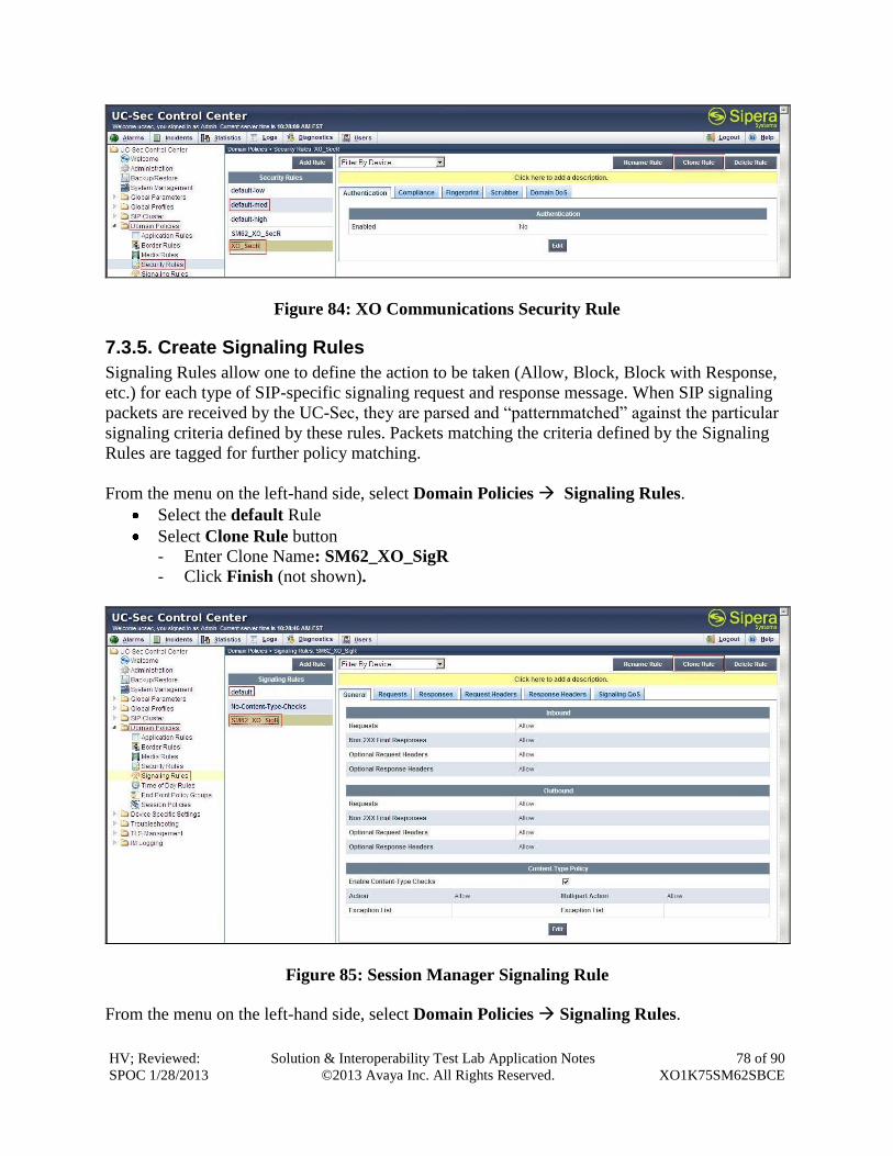
HV; Reviewed:
SPOC 1/28/2013
Solution & Interoperability Test Lab Application Notes
©2013 Avaya Inc. All Rights Reserved.
78 of 90
XO1K75SM62SBCE
Figure 84: XO Communications Security Rule
7.3.5. Create Signaling Rules
Signaling Rules allow one to define the action to be taken (Allow, Block, Block with Response,
etc.) for each type of SIP-specific signaling request and response message. When SIP signaling
packets are received by the UC-Sec, they are parsed and “patternmatched” against the particular
signaling criteria defined by these rules. Packets matching the criteria defined by the Signaling
Rules are tagged for further policy matching.
From the menu on the left-hand side, select Domain Policies Signaling Rules.
Select the default Rule
Select Clone Rule button
- Enter Clone Name: SM62_XO_SigR
- Click Finish (not shown).
Figure 85: Session Manager Signaling Rule
From the menu on the left-hand side, select Domain Policies Signaling Rules.
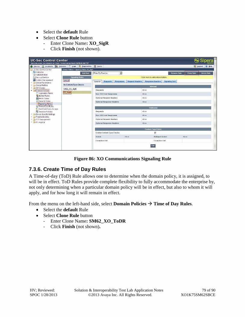
HV; Reviewed:
SPOC 1/28/2013
Solution & Interoperability Test Lab Application Notes
©2013 Avaya Inc. All Rights Reserved.
79 of 90
XO1K75SM62SBCE
Select the default Rule
Select Clone Rule button
- Enter Clone Name: XO_SigR
- Click Finish (not shown).
Figure 86: XO Communications Signaling Rule
7.3.6. Create Time of Day Rules
A Time-of-day (ToD) Rule allows one to determine when the domain policy, it is assigned, to
will be in effect. ToD Rules provide complete flexibility to fully accommodate the enterprise by,
not only determining when a particular domain policy will be in effect, but also to whom it will
apply, and for how long it will remain in effect.
From the menu on the left-hand side, select Domain Policies Time of Day Rules.
Select the default Rule
Select Clone Rule button
- Enter Clone Name: SM62_XO_ToDR
- Click Finish (not shown).
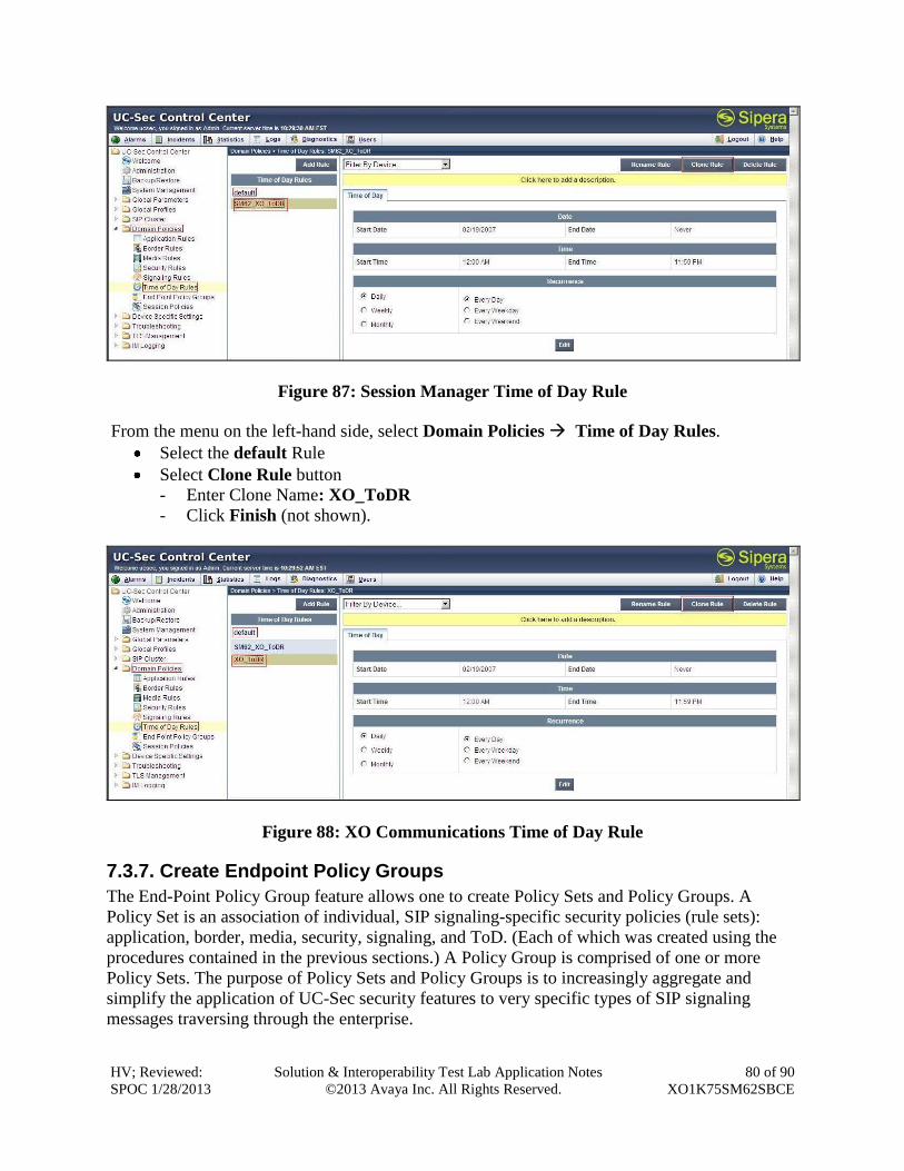
HV; Reviewed:
SPOC 1/28/2013
Solution & Interoperability Test Lab Application Notes
©2013 Avaya Inc. All Rights Reserved.
80 of 90
XO1K75SM62SBCE
Figure 87: Session Manager Time of Day Rule
From the menu on the left-hand side, select Domain Policies Time of Day Rules.
Select the default Rule
Select Clone Rule button
- Enter Clone Name: XO_ToDR
- Click Finish (not shown).
Figure 88: XO Communications Time of Day Rule
7.3.7. Create Endpoint Policy Groups
The End-Point Policy Group feature allows one to create Policy Sets and Policy Groups. A
Policy Set is an association of individual, SIP signaling-specific security policies (rule sets):
application, border, media, security, signaling, and ToD. (Each of which was created using the
procedures contained in the previous sections.) A Policy Group is comprised of one or more
Policy Sets. The purpose of Policy Sets and Policy Groups is to increasingly aggregate and
simplify the application of UC-Sec security features to very specific types of SIP signaling
messages traversing through the enterprise.
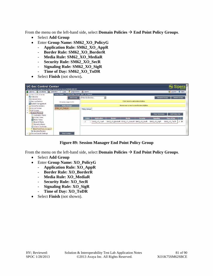
HV; Reviewed:
SPOC 1/28/2013
Solution & Interoperability Test Lab Application Notes
©2013 Avaya Inc. All Rights Reserved.
81 of 90
XO1K75SM62SBCE
From the menu on the left-hand side, select Domain Policies End Point Policy Groups.
Select Add Group
Enter Group Name: SM62_XO_PolicyG
- Application Rule: SM62_XO_AppR
- Border Rule: SM62_XO_BorderR
- Media Rule: SM62_XO_MediaR
- Security Rule: SM62_XO_SecR
- Signaling Rule: SM62_XO_SigR
- Time of Day: SM62_XO_ToDR
Select Finish (not shown).
Figure 89: Session Manager End Point Policy Group
From the menu on the left-hand side, select Domain Policies End Point Policy Groups.
Select Add Group
Enter Group Name: XO_PolicyG
- Application Rule: XO_AppR
- Border Rule: XO_BorderR
- Media Rule: XO_MediaR
- Security Rule: XO_SecR
- Signaling Rule: XO_SigR
- Time of Day: XO_ToDR
Select Finish (not shown).
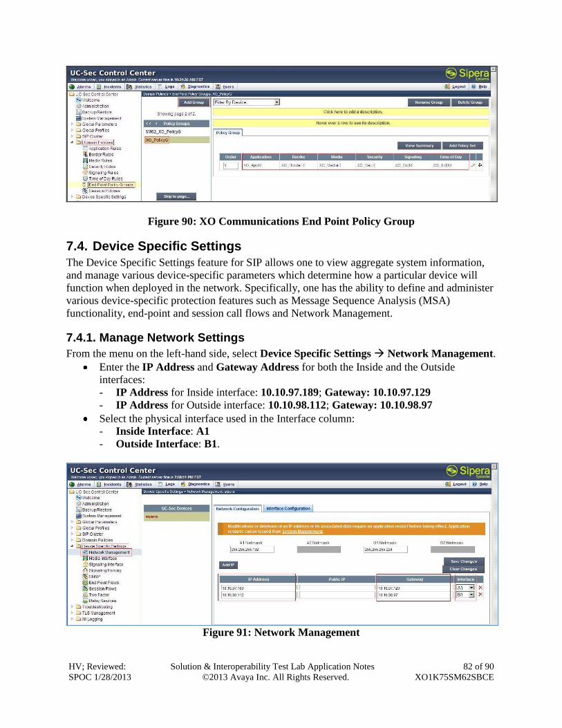
HV; Reviewed:
SPOC 1/28/2013
Solution & Interoperability Test Lab Application Notes
©2013 Avaya Inc. All Rights Reserved.
82 of 90
XO1K75SM62SBCE
Figure 90: XO Communications End Point Policy Group
7.4. Device Specific Settings
The Device Specific Settings feature for SIP allows one to view aggregate system information,
and manage various device-specific parameters which determine how a particular device will
function when deployed in the network. Specifically, one has the ability to define and administer
various device-specific protection features such as Message Sequence Analysis (MSA)
functionality, end-point and session call flows and Network Management.
7.4.1. Manage Network Settings
From the menu on the left-hand side, select Device Specific Settings Network Management.
Enter the IP Address and Gateway Address for both the Inside and the Outside
interfaces:
- IP Address for Inside interface: 10.10.97.189; Gateway: 10.10.97.129
- IP Address for Outside interface: 10.10.98.112; Gateway: 10.10.98.97
Select the physical interface used in the Interface column:
- Inside Interface: A1
- Outside Interface: B1.
Figure 91: Network Management
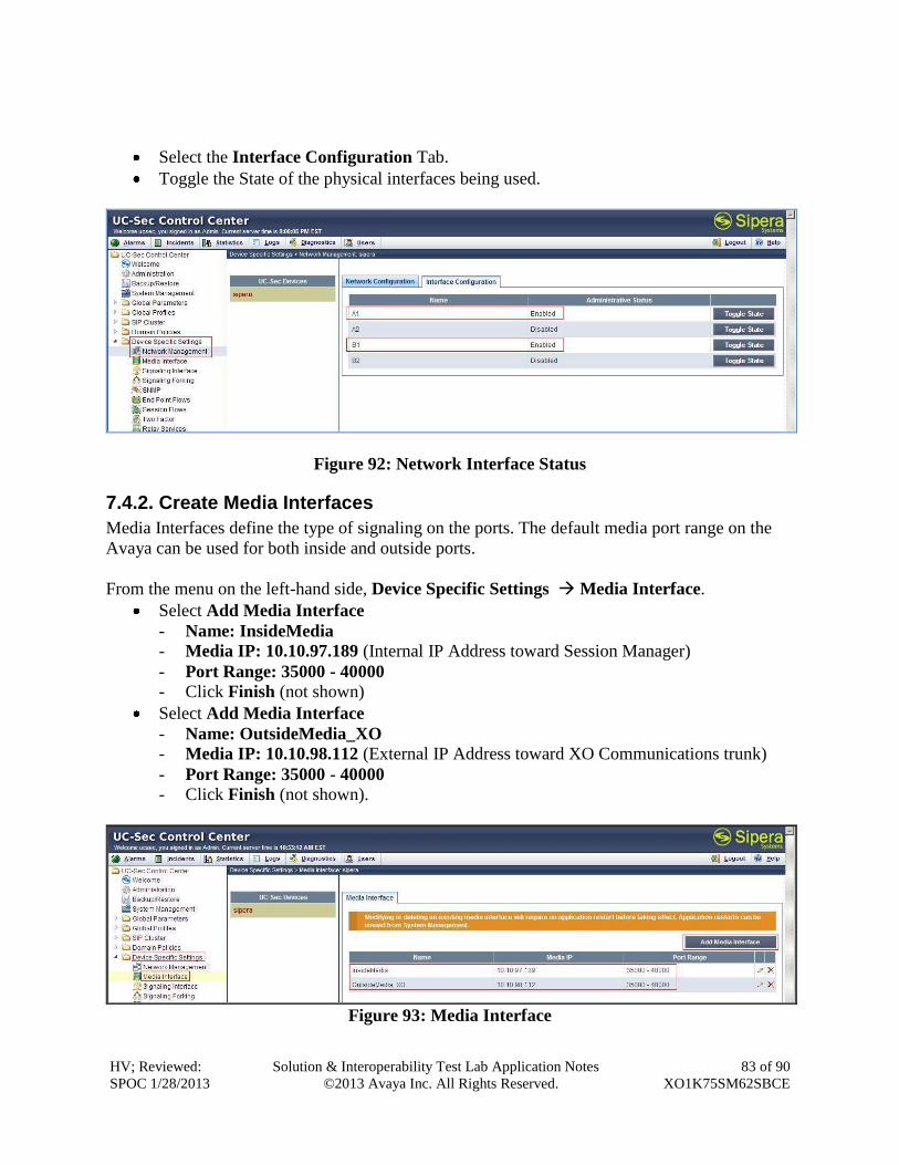
HV; Reviewed:
SPOC 1/28/2013
Solution & Interoperability Test Lab Application Notes
©2013 Avaya Inc. All Rights Reserved.
83 of 90
XO1K75SM62SBCE
Select the Interface Configuration Tab.
Toggle the State of the physical interfaces being used.
Figure 92: Network Interface Status
7.4.2. Create Media Interfaces
Media Interfaces define the type of signaling on the ports. The default media port range on the
Avaya can be used for both inside and outside ports.
From the menu on the left-hand side, Device Specific Settings Media Interface.
Select Add Media Interface
- Name: InsideMedia - Media IP: 10.10.97.189 (Internal IP Address toward Session Manager)
- Port Range: 35000 - 40000 - Click Finish (not shown)
Select Add Media Interface
- Name: OutsideMedia_XO - Media IP: 10.10.98.112 (External IP Address toward XO Communications trunk)
- Port Range: 35000 - 40000 - Click Finish (not shown).
Figure 93: Media Interface
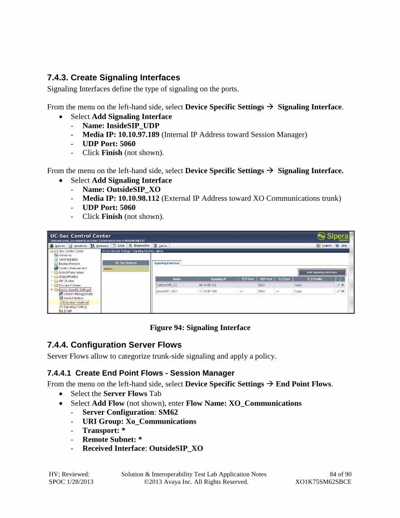
HV; Reviewed:
SPOC 1/28/2013
Solution & Interoperability Test Lab Application Notes
©2013 Avaya Inc. All Rights Reserved.
84 of 90
XO1K75SM62SBCE
7.4.3. Create Signaling Interfaces
Signaling Interfaces define the type of signaling on the ports.
From the menu on the left-hand side, select Device Specific Settings Signaling Interface.
Select Add Signaling Interface
- Name: InsideSIP_UDP - Media IP: 10.10.97.189 (Internal IP Address toward Session Manager)
- UDP Port: 5060 - Click Finish (not shown).
From the menu on the left-hand side, select Device Specific Settings Signaling Interface.
Select Add Signaling Interface
- Name: OutsideSIP_XO - Media IP: 10.10.98.112 (External IP Address toward XO Communications trunk)
- UDP Port: 5060
- Click Finish (not shown).
Figure 94: Signaling Interface
7.4.4. Configuration Server Flows
Server Flows allow to categorize trunk-side signaling and apply a policy.
7.4.4.1 Create End Point Flows - Session Manager
From the menu on the left-hand side, select Device Specific Settings End Point Flows.
Select the Server Flows Tab
Select Add Flow (not shown), enter Flow Name: XO_Communications
- Server Configuration: SM62
- URI Group: Xo_Communications
- Transport: *
- Remote Subnet: * - Received Interface: OutsideSIP_XO
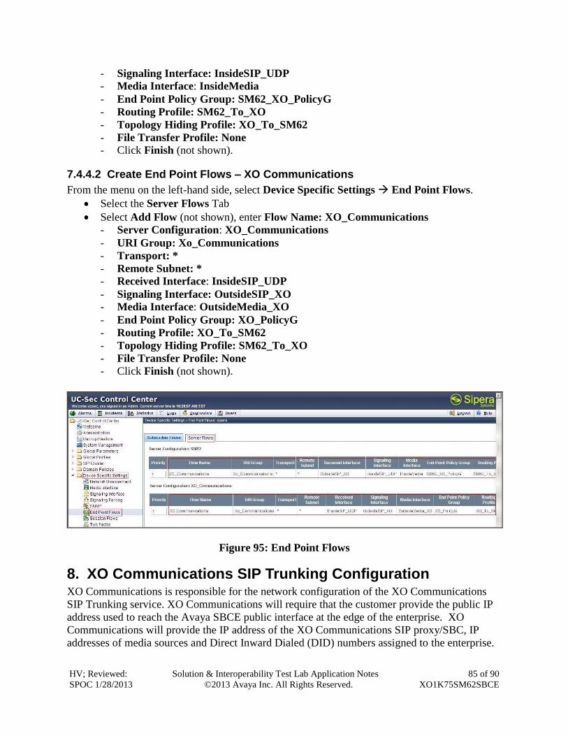
HV; Reviewed:
SPOC 1/28/2013
Solution & Interoperability Test Lab Application Notes
©2013 Avaya Inc. All Rights Reserved.
85 of 90
XO1K75SM62SBCE
- Signaling Interface: InsideSIP_UDP - Media Interface: InsideMedia
- End Point Policy Group: SM62_XO_PolicyG
- Routing Profile: SM62_To_XO
- Topology Hiding Profile: XO_To_SM62
- File Transfer Profile: None - Click Finish (not shown).
7.4.4.2 Create End Point Flows – XO Communications
From the menu on the left-hand side, select Device Specific Settings End Point Flows.
Select the Server Flows Tab
Select Add Flow (not shown), enter Flow Name: XO_Communications
- Server Configuration: XO_Communications
- URI Group: Xo_Communications
- Transport: *
- Remote Subnet: * - Received Interface: InsideSIP_UDP
- Signaling Interface: OutsideSIP_XO - Media Interface: OutsideMedia_XO
- End Point Policy Group: XO_PolicyG
- Routing Profile: XO_To_SM62
- Topology Hiding Profile: SM62_To_XO
- File Transfer Profile: None
- Click Finish (not shown).
Figure 95: End Point Flows
8. XO Communications SIP Trunking Configuration XO Communications is responsible for the network configuration of the XO Communications
SIP Trunking service. XO Communications will require that the customer provide the public IP
address used to reach the Avaya SBCE public interface at the edge of the enterprise. XO
Communications will provide the IP address of the XO Communications SIP proxy/SBC, IP
addresses of media sources and Direct Inward Dialed (DID) numbers assigned to the enterprise.
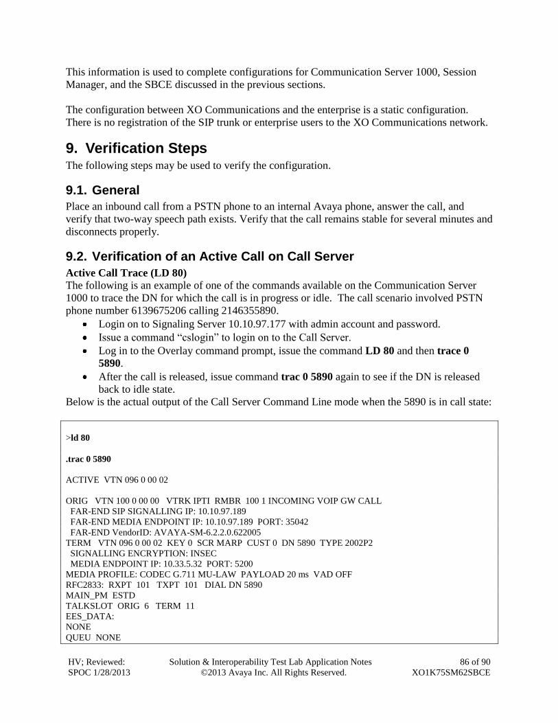
HV; Reviewed:
SPOC 1/28/2013
Solution & Interoperability Test Lab Application Notes
©2013 Avaya Inc. All Rights Reserved.
86 of 90
XO1K75SM62SBCE
This information is used to complete configurations for Communication Server 1000, Session
Manager, and the SBCE discussed in the previous sections.
The configuration between XO Communications and the enterprise is a static configuration.
There is no registration of the SIP trunk or enterprise users to the XO Communications network.
9. Verification Steps The following steps may be used to verify the configuration.
9.1. General
Place an inbound call from a PSTN phone to an internal Avaya phone, answer the call, and
verify that two-way speech path exists. Verify that the call remains stable for several minutes and
disconnects properly.
9.2. Verification of an Active Call on Call Server
Active Call Trace (LD 80)
The following is an example of one of the commands available on the Communication Server
1000 to trace the DN for which the call is in progress or idle. The call scenario involved PSTN
phone number 6139675206 calling 2146355890.
Login on to Signaling Server 10.10.97.177 with admin account and password.
Issue a command “cslogin” to login on to the Call Server.
Log in to the Overlay command prompt, issue the command LD 80 and then trace 0
5890.
After the call is released, issue command trac 0 5890 again to see if the DN is released
back to idle state.
Below is the actual output of the Call Server Command Line mode when the 5890 is in call state:
>ld 80
.trac 0 5890
ACTIVE VTN 096 0 00 02
ORIG VTN 100 0 00 00 VTRK IPTI RMBR 100 1 INCOMING VOIP GW CALL
FAR-END SIP SIGNALLING IP: 10.10.97.189
FAR-END MEDIA ENDPOINT IP: 10.10.97.189 PORT: 35042
FAR-END VendorID: AVAYA-SM-6.2.2.0.622005
TERM VTN 096 0 00 02 KEY 0 SCR MARP CUST 0 DN 5890 TYPE 2002P2
SIGNALLING ENCRYPTION: INSEC
MEDIA ENDPOINT IP: 10.33.5.32 PORT: 5200
MEDIA PROFILE: CODEC G.711 MU-LAW PAYLOAD 20 ms VAD OFF
RFC2833: RXPT 101 TXPT 101 DIAL DN 5890
MAIN_PM ESTD
TALKSLOT ORIG 6 TERM 11
EES_DATA:
NONE
QUEU NONE
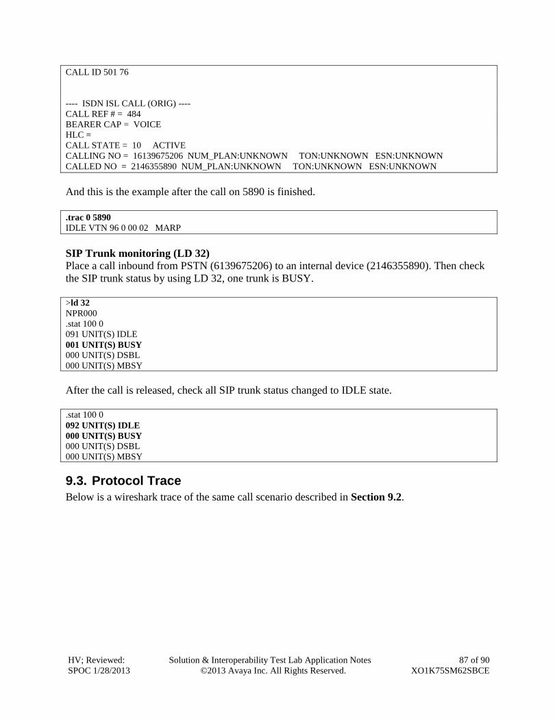
HV; Reviewed:
SPOC 1/28/2013
Solution & Interoperability Test Lab Application Notes
©2013 Avaya Inc. All Rights Reserved.
87 of 90
XO1K75SM62SBCE
CALL ID 501 76
---- ISDN ISL CALL (ORIG) ----
CALL REF # = 484
BEARER CAP = VOICE
HLC =
CALL STATE = 10 ACTIVE
CALLING NO = 16139675206 NUM_PLAN:UNKNOWN TON:UNKNOWN ESN:UNKNOWN
CALLED NO = 2146355890 NUM_PLAN:UNKNOWN TON:UNKNOWN ESN:UNKNOWN
And this is the example after the call on 5890 is finished.
.trac 0 5890
IDLE VTN 96 0 00 02 MARP
SIP Trunk monitoring (LD 32)
Place a call inbound from PSTN (6139675206) to an internal device (2146355890). Then check
the SIP trunk status by using LD 32, one trunk is BUSY.
>ld 32
NPR000
.stat 100 0
091 UNIT(S) IDLE
001 UNIT(S) BUSY
000 UNIT(S) DSBL
000 UNIT(S) MBSY
After the call is released, check all SIP trunk status changed to IDLE state.
.stat 100 0
092 UNIT(S) IDLE
000 UNIT(S) BUSY
000 UNIT(S) DSBL
000 UNIT(S) MBSY
9.3. Protocol Trace
Below is a wireshark trace of the same call scenario described in Section 9.2.
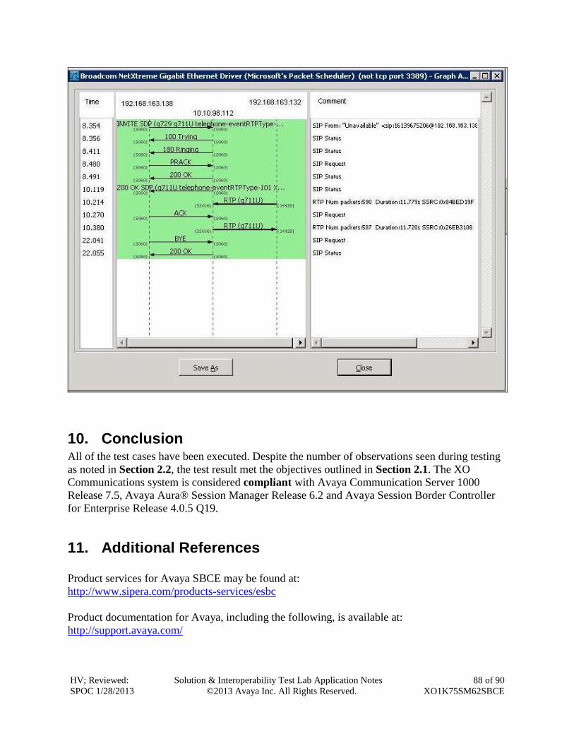
HV; Reviewed:
SPOC 1/28/2013
Solution & Interoperability Test Lab Application Notes
©2013 Avaya Inc. All Rights Reserved.
88 of 90
XO1K75SM62SBCE
10. Conclusion All of the test cases have been executed. Despite the number of observations seen during testing
as noted in Section 2.2, the test result met the objectives outlined in Section 2.1. The XO
Communications system is considered compliant with Avaya Communication Server 1000
Release 7.5, Avaya Aura® Session Manager Release 6.2 and Avaya Session Border Controller
for Enterprise Release 4.0.5 Q19.
11. Additional References
Product services for Avaya SBCE may be found at:
http://www.sipera.com/products-services/esbc
Product documentation for Avaya, including the following, is available at:
http://support.avaya.com/
HV; Reviewed:
SPOC 1/28/2013
Solution & Interoperability Test Lab Application Notes
©2013 Avaya Inc. All Rights Reserved.
89 of 90
XO1K75SM62SBCE
[1] Network Routing Service Fundamentals, Avaya Communication Server 1000, Release 7.5,
Document Number NN43001-130, Revision 03.10, September 2011.
[2] IP Peer Networking Installation and Commissioning, Avaya Communication Server 1000,
Release 7.5, Document Number NN43001-313, Revision: 05.09, October 2011.
[3] Communication Server 1000E Overview, Avaya Communication Server 1000, Release 7.5,
Document Number NN43041-110, Revision: 05.05, October 2011.
[4] Unified Communications Management Common Services Fundamentals, Avaya
Communication Server 1000, Release 7.5, Document Number NN43001-116, Revision 05.17,
January 2012.
[5] Communication Server 1000 Dialing Plans Reference, Avaya Communication Server 1000,
Release 7.5, Document Number NN43001-283, Revision 05.02, November 2010.
[6] Product Compatibility Reference, Avaya Communication Server 1000, Release 7.5,
Document Number NN43001-256, Revision 05.03, December 2011.
[7] Administering Avaya Aura® Session Manager, Doc ID 03-603324, Release 6.2, July 2012.
[8] Administering Avaya Aura® System Manager, Release 6.2, July 2012.
[9] Maintaining and Troubleshooting Avaya Aura® Session Manager, Doc ID 03-603325,
Release 6.2, August 2012.
HV; Reviewed:
SPOC 1/28/2013
Solution & Interoperability Test Lab Application Notes
©2013 Avaya Inc. All Rights Reserved.
90 of 90
XO1K75SM62SBCE
©2013 Avaya Inc. All Rights Reserved.
Avaya and the Avaya Logo are trademarks of Avaya Inc. All trademarks identified by ® and
™ are registered trademarks or trademarks, respectively, of Avaya Inc. All other trademarks
are the property of their respective owners. The information provided in these Application
Notes is subject to change without notice. The configurations, technical data, and
recommendations provided in these Application Notes are believed to be accurate and
dependable, but are presented without express or implied warranty. Users are responsible for
their application of any products specified in these Application Notes.
Please e-mail any questions or comments pertaining to these Application Notes along with the
full title name and filename, located in the lower right corner, directly to the Avaya
DevConnect Program at [email protected].