application of a high resistance grounding (hrg) unit to an esp …€¦ · · 2014-07-16well...
TRANSCRIPT

APPLICATION OF A HIGH RESISTANCE GROUNDING (HRG) UNIT TO AN ESP WITHIN A HAZARDOUS AREA 2014 EUALF
When conventional attempts to eliminate electrical discharge activity in a zone 1 hazardous area associated with an earth faulted ESP failed, the system was isolated and the back-up system brought online. When the backup system failed an alternative approach to the problem was attempted.
This presentation will look at the following:
How the fault led to above surface electrical discharge activity
How the application of a High Resistance Grounding Unit eliminated the problem
INTRODUCTION
2

Well completed as a dual ESP operated via a Variable Speed Drive (VSD)
Primary ESP developed earth fault within first weeks of operation
Floating neutral VSD system allowed for continued operation of faulted ESP
Gauge of backup ESP connected to maintain downhole data
After 16 months operation electrical discharge noticed in wellbay area during routine checks
Well taken offline and investigations commenced – earlier earth faulted had further degraded
BACKGROUND
3
Electrical discharge from instrument pipework
Three leg electrical penetrator

Tree earthing checked and supplemented
Equipotential bonding applied to all extraneous metalwork
Backup gauge system isolated (remove alternative power sources)
Backup ESP system isolated (removed circulating current paths)
Voltage in offline ESP system checked
Electrical discharge potential still present – measurable as voltage difference between adjacent bonded metalwork
CONVENTIONAL SOLUTIONS
4

Primary ESP mothballed due to discharge
Backup ESP brought into operation
Well operated for further 22 months until backup ESP failure (suspect motor bearing failure)
Opportunity to to re-use primary ESP if electrical discharge potential could be eliminated
INTERIM OPERATION
5
Sharp increase in amps prior to eventual failure

Time Domain Reflectrometry employed to determine location of fault
Information indicates low impedance earth fault located high in completion (immediately below or within tree)
Repair attempted by replacing intermediate connectors but ineffective – required completion to be pulled
Multiple additional earth bonding jumpers attached to tree and pipework – no success
Fault location and severity causing capacitive charging of local earth plane
Capacitive charge unable to dissipate as supply system (VSD) unearthed
FURTHER INVESTIGATIONS
6
Fault current requires return path to prevent capacitive charging
VSD not suitable for operating with earthed star point
High Resistance Grounding Unit (HRGU) being evaluated to extend run life of earth faulted ESP wells
Decision to employ HRGU to provide return path for fault current
ALTERNATIVE SOLUTION
7

HV/LV transformer in Star/Broken Delta configuration
HV star point grounded to provide earth fault current return path
Open Delta secondary winding closed using high power rating resistor
Current flow in primary matched (at transformer ratio) with current flow in secondary
Secondary winding resistor limits primary (fault) current
HIGH RESISTANCE GROUNDING UNIT
8

HIGH RESISTANCE GROUNDING UNIT-BETA UNIT
9
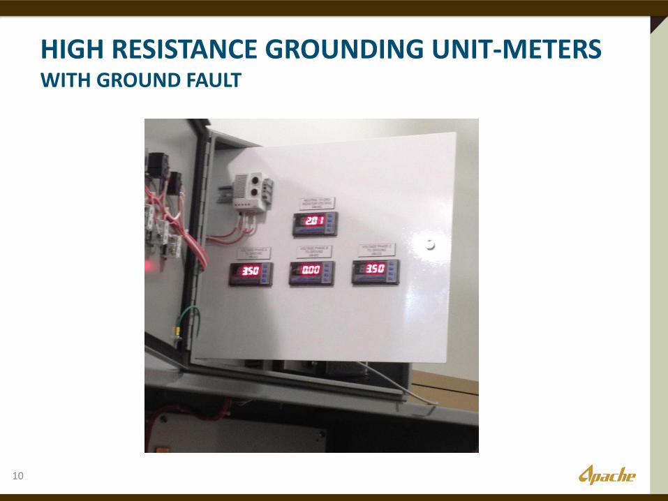
HIGH RESISTANCE GROUNDING UNIT-METERS WITH GROUND FAULT
10

HIGH RESISTANCE GROUNDING UNIT PRODUCTION UNIT
11

HRGU connected in parallel with VSD output-at VSD
VSD operated at low output voltage to determine fault levels
HRGU instrumentation indicates earth fault impedance near zero
Secondary winding resistor value altered to limit fault current to ~2 Amps
VSD run up to operating voltage and frequency
Electrical discharge potential voltages still present in well bay area
INITIAL OPERATION
12

Analysis of installation indicates parallel earth paths to HRGU through platform metalwork and supply cable braid
Need to provide ‘preferential’ path for earth fault current
Low impedance path provided from close to fault site to HRGU (large diameter earth conductor following path of main conductors)
Makes the Tree the New Earth Fault Location – No Stray Currents thru Piping!
VSD run up to operating voltage and frequency
No electrical discharge potential voltages measurable in well bay area
REVISED OPERATION
13

Well brought back online at production rate of ~980 BOPD
Well operated for further 10 days
Suspect motor failed mechanically (i.e. not directly related to earth fault)
Cost of HRGU purchase and installation recouped within first 3 days of additional production
HRGU technology and application proven – electrical discharge potential from earth faulted ESP eliminated
EXTENDED RUN-LIFE
14
8.4Mbo additional production
ACKNOWLEDGEMENTS
15