application of an ads-b sense and avoid algorithm
TRANSCRIPT

1
American Institute of Aeronautics and Astronautics Patent Pending: Patent App No. 13/785,661
Application of an ADS-B Sense and Avoid Algorithm
Ricardo Arteaga1
NASA Armstrong Flight Research Center, Edwards, California 93523
Robert Kotcher2
Expii, Inc., Pittsburgh, Pennsylvania 15213
Moshe Cavalin3
Brandeis University, Waltham, Massachusetts 02453
and
Mohammed Dandachy4
NASA Armstrong Flight Research Center, Edwards, California 93523
The National Aeronautics and Space Administration Armstrong Flight Research
Center in Edwards, California is leading a program aimed towards integrating unmanned
aircraft system into the national airspace system (UAS in the NAS). The overarching goal of
the program is to reduce technical barriers associated with related safety issues as well as
addressing challenges that will allow UAS routine access to the national airspace. This
research paper focuses on three novel ideas: (1) A design of an integrated UAS
equipped with Automatic Dependent Surveillance-Broadcast that constructs a more
accurate state-based airspace model; (2) The use of Stratway Algorithm in a real-time
environment; and (3) The verification a nd validation of sense and avoid performance and
usability test results which provide a pilot’s perspective on how our system will benefit
the UAS in the NAS program for both piloted and unmanned aircraft.
Nomenclature
ADS-B = Automatic Dependent Surveillance-Broadcast
ATC = air traffic control
CPA = closest point of approach
D = ownship horizontal separation distance
EPU = estimated position uncertainty
FAA = Federal Aviation Administration
GCS = ground control station
GPI = Generic Payload Interface
GPS = global positioning system
H = ownship vertical separation distance
ICAO = International Civil Aviation Organization
i = set of intruder targets (t0, t1, · · ·)
NAS = United States National Airspace System
NACP = navigation accuracy category for position (ADS-B accuracy parameter) NACV = navigation accuracy category for velocity (ADS-B accuracy parameter)
1 Systems Engineer, Sensors & Systems Development Branch, P.O. Box 273 Edwards, California/Mail Stop
4840D, non-member. 2 Software Engineer, 128 Oakland Ave., Pittsburgh, Pennsylvania, non-member. 3 Student Contractor, Sensors & Systems Development Branch, P.O. Box 273 Edwards, California/Mail Stop
4840D, non-member. 4 Systems Engineer, Vehicle Integration & Test Branch, P.O. Box 273 Edwards, California/Mail Stop 4800/1013,
non-member.
2
American Institute of Aeronautics and Astronautics Patent Pending: Patent App No. 13/785,661
NASA = National Aeronautics and Space Administration
NIC = navigation integrity category (ADS-B integrity parameter)
o = ownship
RA = O’s resolution advisory, consisting of waypoints (w0, w1, w2, · · · ), visual, and vocal alerts
RC = radius of containment
SAA = sense and avoid
SDA = system design assurance
SIL = source integrity level
TCAS II = Traffic Alert and Collision Avoidance System II
tCPA = time to closest point of approach
tL = look ahead time
UAS = unmanned aircraft system (aircraft, ground station, command and control link)
UAT = universal access transceiver
UX = usability
vi = velocity intruder
vo = velocity ownship
WAAS = Wide Area Augmentation System
I. Introduction
UTOMATIC Dependent Surveillance-Broadcast (ADS-B) is a new technology that is helping to improve
the safety and efficiency of air traffic control. In general, ADS-B Out refers to the broadcast of ownship state
information of an appropriately equipped aircraft. ADS-B In refers to the ability of an appropriately equipped
aircraft to receive and display ADS-B information from other aircraft. ADS-B communicates through radio
frequency and improves on the existing radar-based system in the following ways:
1) It tracks aircraft position with a much higher resolution and lower error rate (NACp of 8 or 9, instead of
6 or 7).1,2
2) Without the mechanical constraints of radar-based systems, ADS-B systems can update an aircraft state
much faster (typically 1Hz, instead of once every 12 seconds).
As part of a next generation air traffic control (ATC) system, the U.S. Federal Aviation Administration (FAA)
has mandated that all aircraft operating within the National Airspace System (NAS) class A airspace be equipped
with ADS-B Out technology by 2020.2,3
Pilots at the National Aeronautics and Space Administration (NASA) are beginning to use ADS-B hardware on their
aircraft. The resulting increase of in-flight data volume has led many NASA centers to independently develop
in-flight software aides that both sense future loss of separation and provide advisories to navigate aircraft out of
conflict with one another.
This research paper discusses the implementation of a new ADS-B-based sense and avoid (SAA) system that
detects future loss of separation and provides 3D visual and aural conflict resolution advisories ( R A s ) using the
Stratway algorithm4 to provide the unmanned aircraft system (UAS) pilot in command awareness of proximate
traffic as well as suggestive guidance on how to avoid loss of separation.
A. ADS-B System Architecture
ADS-B technology transmits data over air-to-air and air-to-ground communication. As shown in Fig. 1, a central
unit in the system is an ADS-B transceiver (GDL-90) that also receives global positioning system (GPS) satellite
signals. The system also has an altitude encoder, which allows transponder data to contain additional altitude
information. The ADS-B Out broadcast information contains position, velocity, identity, and altitude; and is
transmitted at 978 MHz. Two antennas are needed to complete the system. The GPS/Wide Area Augmentation
System (WAAS) antenna receives GPS satellite signals, and the universal access transceiver (UAT) antennas
broadcast the data packets of the ownship. The ADS-B In messages are received via UAT antennas and are processed
by the UAT as ADS-B/Automatic Dependent Surveillance-Re-Broadcast/Traffic Information Services-Broadcast
(TIS-B) message reports. These ADS-B In message reports are encoded in the packet-based ADS-B messages, and
are sent via serial asynchronous telemetry communications to the ground control station (GCS) for software display.
In March 2012, NASA flew ADS-B Out (outgoing ownship data) on the Ikhana (MQ-9 Predator) (General
Atomics Aeronautical Systems Incorporated, San Diego, California) UAS. It was the first time that a large UAS
had flown equipped with ADS-B (ADS-B Out). The Ikhana MQ-9 UAS was certified using the Advisory Circular
AC-20-165, Airworthiness Approval of Automatic Dependent Surveillance-Broadcast (ADS-B) Out Systems.3
A

3
American Institute of Aeronautics and Astronautics Patent Pending: Patent App No. 13/785,661
Figure 1. ADS-B Out system architecture (Patent filed March 5, 2013; Serial No. 13/785,661).5
According to an analysis report issued by the FAA, the ADS-B system on Ikhana (NASA 870) performed
exceptionally well, easily exceeding the mandated requirements. These ADS-B Out performance requirements
are shown in Table 1.
Table 1. FAA mandated accuracy and integrity requirements and UAS results.
Parameter Requirement Accuracy NASA 870
NIC ≥ 7 RC < 370.4 m (0.2 nm) 10
NACP ≥ 8 EPU < 92.6 m (0.05 nm) 10
NACV ≥ 1 < 10 m/s 2
SIL ≥ 3 ≤ 1x10⁻⁷ per hour or sample 3
SDA ≥ 2 ≤ 1x10⁻⁵ per hour 2
The results of horizontal position accuracy measured µ = 5.7 ft and σ = 3.1 ft, which is expressed in
mathematical notation as Pr 2 .954x (i.e., x ≤ 11.9 ft) and easily satisfied the FAA mandated position
accuracy of 0.05 nm (304 ft) with probability of 95%.
In May 2012, two successful flight tests of the Ikhana MQ-9 (Fig. 2) were carried out at NASA Armstrong
Flight Research Center (AFRC) (Edwards, California). This time, the aircraft was equipped with ADS-B Out
and ADS-B In. The ADS-B surveillance platform described in this paper was used to track the Ikhana MQ-9 during
these flights, and since then additional SAA capabilities have been added to the software to increase situational
awareness for both pilots and air traffic control (ATC).

4
American Institute of Aeronautics and Astronautics Patent Pending: Patent App No. 13/785,661
Figure 2. Ikhana MQ-9 unmanned vehicle (NASA photo ED12-0082-22).
B. ADS-B System Hardware The ADS-B Transceiver (GDL-90/88 or Freeflight 978-XVR) is the central hardware unit in an ADS-B system.
It has two main purposes: First, it synthesizes ownship data from the GPS antenna reception and altitude
encoder. It also transmits ownship in forma t ion and receives traffic data from its UAT antennas, which are
attached to the fuselage of the ownship.
The ADS-B transceiver unit assembles data messages and sends outputs to telemetry once every second. The
data message contains two main components. The first, called the heartbeat, describes the status of the GPS
solution and ADS-B transceiver health and status. The second contains flight parameters including traffic type,
International Civil Aviation Organization (ICAO) code, latitude, longitude, barometric altitude, air/ground status,
velocity, heading, call sign, emitter category, navigation integrity (NIC), and navigation accuracy (NACp and
NACV). The GPS altitude and traffic data are also sent with the message.
The Ikhana-to-GCS downlink message is transmitted at 1 Hz to provide enough information regarding the
aircraft state and traffic data in order to give the GCS operator good situational awareness on the ADS-B In
display. The ADS-B In display and SAA software were developed at NASA AFRC for the visualization of the
Ikhana MQ-9 ownship and surveillance traffic using the transmission protocols of aircraft telemetry.
C. ADS-B Sense and Avoid Software
Fundamentally, what makes this ADS-B technology work on a UAS is NASA developed software and
algorithms. To increase situational awareness of UAS pilots, a novel system for displaying ownship and ADS-B
traffic information was developed. The patent pending ADS-B SAA display integrated with the Stratway
algorithm4 provides the pilot with three general categories of information intended to support: (1) situation
awareness, (2) conflict detection, and (3) conflict resolution. Figure 3 shows a screen shot of the ADS-B traffic
display with an example self-separation encounter that highlights many of the important informational features of
the display, including:
The intruder and encounter information data,
The conflict detection (sphere),
The traffic selection and data,
The range selection with automatic zoom,
The ownship selection for sense and avoid, and
The sense and avoid toggle on/off function for selected target.
The NASA developed SAA software performs real-time conflict detection and self-separation (i.e. remaining
“well clear” of other air traffic) using the SAA sub-functions, as shown in Table 2 below. Basically, target
detection is accomplished by the ADS-B transceiver, which can either be airborne or on the ground. The Stratway
algorithm is then used for detecting conflicts as well as performing self-separation avoidance maneuvers. The
RAs are visual and vocalized alerts that direct the pilot to increase separation.

5
American Institute of Aeronautics and Astronautics Patent Pending: Patent App No. 13/785,661
Figure 3. NASA display software.
Table 2. Sense and avoid sub-functions.6
Sub-Functions Explanation
Detect: Detect presence of aircraft in vicinity of UAS
Track: Estimate position and velocity (state) of intruders based on one or more
surveillance reports
Evaluate: Assess collision risk based on intruder and UAS states
Prioritize: Prioritize intruder tracks based on a collision risk threshold
Declare: Decide that action is needed
Determine: Determine what action is required
Command: Communicate determined action to UAS
Execute: Execute the determined action
D. Stratway Algorithm The Stratway algorithm4 was developed at the NASA Langley Research Center (Hampton, Virginia), and is a
modular approach to finding strategic resolutions to conflicts between aircraft. Until now, the algorithm has
mainly been used in class A airspace to resolve long-term conflicts, but the authors of Stratway wanted to decouple
the separation algorithm from any particular flight plan/trajectory generator. The rationale for using the Stratway
algorithm was twofold: (1) the algorithm was modular and could be modified to incorporate accurate short-term
ADS-B trajectory state data; and (2) the software was open-source code from NASA Langley.
In this research paper, the Stratway algorithm will be shown to effectively maintain a safe separation
distance well clear between aircraft in real-time. A unique aspect of this research is the use of an advanced
algorithm that was intended for long-term flight plan manipulation adapted to use accurate short-term
ADS-B velocity state trajectory estimations.
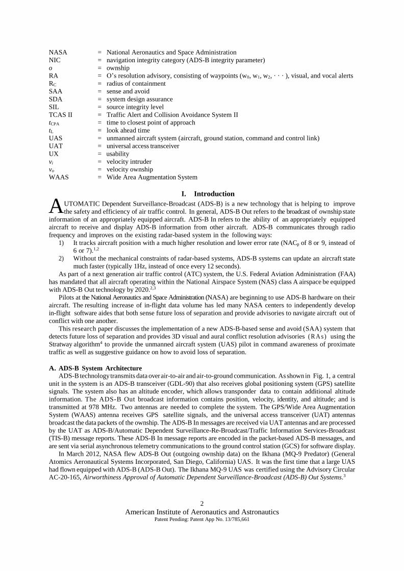
In the Stratway algorithm (Fig. 4) a main processing loop is returned when a solution has been found, a
partial solution has been found, or too much time has been spent searching for one. A solution is found by
iterating resolution strategy and then iterating over its parameters. Strategies can be assigned priorities a priori
and each candidate solution is given to a conflict detector to determine whether or not it is a safe solution to
fly.
6
American Institute of Aeronautics and Astronautics Patent Pending: Patent App No. 13/785,661
Figure 4. Schematic of the NASA Stratway algorithm.
In general, the Stratway algorithm is not designed to be used for a specific aircraft, consequently unique aircraft
capabilities and operational limits (e.g. climb and descent rates, turn rates, and g-limits) must be passed as
parameters before it can be assured that solutions will be reasonable. This process ensures that resulting RAs do
not instruct pilots to fly unsafe maneuvers.
Due to the modular nature of the algorithm, Stratway leaves implementation of strategies up to the developers.
While many strategies are iterative in practice, analytical strategies can be used equally as effectively. The only
requirement on a strategy is that it makes changes to a flight plan and can describe the indices at which the changes
occur. When an initial conflict is found with the Stratway internal conflict detector, it is summarized in a conflict
object and passed to the constructor of a new Stratway object.
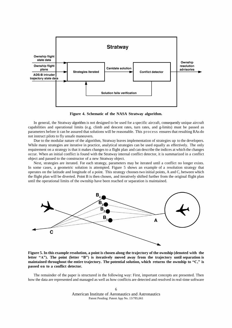
Next, strategies are iterated. For each strategy, parameters may be iterated until a conflict no longer exists.
In some cases, a geometric solution is attempted. Figure 5 shows an example of a resolution strategy that
operates on the latitude and longitude of a point. This strategy chooses two initial points, A and C, between which
the flight plan will be diverted. Point B is then chosen, and iteratively shifted further from the original flight plan
until the operational limits of the ownship have been reached or separation is maintained.
Figure 5. In this example resolution, a point is chosen along the trajectory of the ownship (denoted with the
letter “A”). The point (letter “B”) is iteratively moved away from the trajectory until separation is
maintained throughout the entire trajectory. The potential solution, which returns the ownship to “C,” is
passed on to a conflict detector.
The remainder of the paper is structured in the following way: First, important concepts are presented. Then
how the data are represented and managed as well as how conflicts are detected and resolved in real-time software

7
American Institute of Aeronautics and Astronautics Patent Pending: Patent App No. 13/785,661
are described. In Section IV pilot feedback is presented, as well as results from simulation verification tests and
validation tests with live traffic data.
II. Background
The design of air traffic conflict detection and resolution systems involves the use of airspace models and cost
functions for comparing the cost of aircraft maneuvers. The paper entitled, “Survey of Conflict Detection and
Resolution Modeling Methods,”7 studies about thirty methods for modeling and classifying airspace using metrics
such as propagation method, dimensions, uncertainty, et cetera. For research involving RAs, additional groupings
are made. In this background section, some of the high level methods that are used to distinguish airspace
modeling, conflict detection, and conflict resolution are presented.
A. Trajectory Propagation Methods
A trajectory propagation describes possible future positions of an aircraft. Due to both the uncertainty in
the state data saved as a contrail and unpredictability of a pilot’s future intent, there is error inherent in all internal
trajectory representations. For an SAA display system such as the one presented in this paper, trajectory
propagation is most important as a means for relaying this internal state of our system to the user.
As shown in Fig. 6, a nominal propagation shows only the most probable aircraft trajectory. Many pilots
surveyed were most accustomed to nominal trajectories. At the other extreme is the worst-case propagation, and
just as the name implies, shows a trajectory region that the aircraft will most likely stay inside. Finally, the
probabilistic trajectory is a more detailed representation of an aircraft trajectory that assigns weights to different
airspace regions.
Figure 6. Most common trajectory propagation methods: A) nominal, B) worst-case, C) probabilistic.
This approach uses the nominal trajectory propagation for a variety of reasons. First, the limited data available
in ADS-B traffic messages make the worst-case or probabilistic trajectories more difficult to ensure sufficient
reliability. Perhaps more importantly, the objective is to develop a system that would be easy to use during flight.
A congested airspace (e.g., near an airport) of worst-case or probabilistic propagations would likely make the
display difficult to interpret and possibly unsafe.
The nominal trajectory propagation approach uses an exponentially weighted moving average (EWMA) filter
to filter out the fluctuations in ADS-B vertical state data since altitude and vertical velocity measurements tend to
be relatively noisy due to quantization. The filter is recursive, efficient, and useful for maneuvering aircraft with
newer measurements having a greater influence and thus improves SAA alerting performance.
B. Resolution Methods
A conflict resolution modifies the ownship trajectory according to a set of rules. The modification rules
include maintaining certain separation distances while maneuvering the ownship within its operating limitations.

8
American Institute of Aeronautics and Astronautics Patent Pending: Patent App No. 13/785,661
Generally, conflict resolutions can be classified as either prescribed or optimized. A prescribed resolution has
been determined before runtime based on a set of procedures. For example, a ground proximity warning system8
issues a standard “pull up” advisory when an aircraft trajectory is in conflict with terrain. In contrast, an optimized
resolution attempts to maximize or minimize a cost function.
Stratway is an optimized resolution, and the way in which we present its output to the end user is specific enough
to ensure that it is treated as such. Our strategy instructions are accompanied by details including maximum bank angle
(limits the bank angle an aircraft can achieve) and maximum rate of climb and descent for the respective maneuvers.
This approach helps to ensure the ownship remains conflict-free in scenarios with multiple target aircraft.
III. Detecting and Resolving Conflicts
This research work on SAA uses the Stratway algorithm to help pilots stay well clear of other aircraft, that is
maintain a safe separation distance between each other. Using the Stratway algorithm in a dynamic environment
involves an additional suite of tools and modifications, which was written around the original Stratway code.
It is important to understand the difference between a trajectory propagation and an RA. During program
runtime, we are continuously updating trajectory propagations for each aircraft (i) in the airspace, that is, we are
estimating the position and velocity vectors of an aircraft based on the ADS-B states that have been observed thus
far. We can use this information to determine if two aircraft will lose separation during some look-ahead time tL.
An RA consists of a single set of waypoints (trajectory change path), visual and vocalized alerts, typically for the
ownship, that describe a strategy for increasing separation for intruders that are determined to be collision threats.
The variable names D and H are often used to describe the width and height of various separation volumes. D
represents the minimum horizontal separation distance, in nautical miles, that two aircraft can have before
separation is lost; and H represents the vertical separation distance in feet. More specifically, as shown in Eq. (1),
two aircraft are in loss of separation if:
2 22
2 21
z yzw ww
H D
(1)
IV. Test Results
The approach described in the previous section was included in new software currently being
developed at NASA AFRC. As part of the software verification and validation and in the interest of
releasing the software to government and commercial users, a series of tests was conducted. The test
phase is broken down into three categories: (1) pilot usability (UX) testing to collect feedback from
experienced pilots at NASA AFRC, (2) verification testing to verify and validate SAA alerting performance in a
simulation environment, and (3) live validation testing to test software performance in real aircraft flying
avoidance maneuvers. Pilot usability testing allowed for refining the way in which information was shown to the pilots. Verification
testing provided verification of RA maneuvers, closest point of approach (CPA) predictions, and the self-
separating/alerting logic in the SAA platform. Finally, live validation testing helped validate that the software both
works correctly outside of the simulation environment and that the hardware can be installed onboard real aircraft
within a reasonable resource budget. The items are described in more detail in the following sections.
A. Pilot Usability (UX) Testing
Before testing with live aircraft, NASA pilots were asked to score the performance and user experience of our
software. A simulation tool was developed in order to evaluate SAA maneuver time requirements for a set of
aircraft models over a broad range of encounter geometries. The tool was designed into the SAA software as a
simulation mode to model the 6-degrees-of-freedom of aircraft motion. The tool supports the three axes of motion
for any given aircraft maneuver (i.e., vertical climb/descent, level turns, or speed up/slow down). Each pilot was
asked to fly an encounter scenario, such as the scenario shown in Fig. 7, in this simulated environment after having
received minimal instructions on how to use the software. Each encounter scenario had at least one future loss of
separation in the horizontal or vertical dimension. At the onset of the simulation, the two aircraft were on a direct
collision course. The CPA and alerting times were the primary parameters of interest when flying an RA. Table 3
provides an overview of findings, which is discussed in detail below.

9
American Institute of Aeronautics and Astronautics Patent Pending: Patent App No. 13/785,661
Figure 7. An example resolution that pilots were asked to simulate.
Table 3. Results of pilot usability testing.
Pilot information Pilot 1 Pilot 2 Pilot 3 Pilot 4 Pilot 5 Average
Pilot type: fighter -
Pilot type: large trans. - -
Pilot type: GA -
Pilot type: UAV - - -
Hours of flight exp. 7500 3315 8000 5500 6100
Years of flight exp. 26 14 35 26 30
Conflict detection
Usefulness of alert 10 10 8 9 9 9.2
Accuracy of alert 10 10 9 9 10 9.6
Safety of alert 10 10 9 9 8 9.2
Recognized conflict existed 10 10 7 9 9 9
Could determine location 10 8 7 10 9 8.8
Good sense of remaining time 10 9 9 10 10 9.6
Was sufficient to de-conflict 10 10 9 9 10 9.6
Conflict resolution
Usefulness of alert 7 9 8 7 8 7.8
Accuracy of alert 7 9 8 9 8 8.2
Safety of alert 10 8.5 8 9 9 8.9
Effectiveness of alert 10 8.5 8 9 9 8.9
Could follow visually 8 9 8 8 9 8.4
Could follow aurally 5 8 8 9 9 7.8
Overall situational awareness 8 9 7 9 7 8
1. General System Parameters
The system parameters discussed with the pilots centered on distances and times used as thresholds for

10
American Institute of Aeronautics and Astronautics Patent Pending: Patent App No. 13/785,661
activating advisories and alerts. The items included look-ahead time, velocity vector length, separation volumes
used, and the advisory compliance threshold.
In general, the pilots agree that five minutes is a reasonable look-ahead time, and should not be exceeded.
The look-ahead time is a value that describes how many minutes into the future the system studies when detecting
and resolving conflicts. Pilot1 (as in Table 3) suggested that the number may be more effective at four minutes, in
the case that the ATC and the system itself do not give their advisories at the same exact time.
As with the look-ahead time, the pilots generally agreed that 90 seconds is a reasonable velocity vector
length. Pilots voiced mixed opinions on whether the vector should follow a line or follow the arc of the current
turn of the aircraft. Some preferred to stay with the current linear convention, while others suggested that a curve
might be more informative if it could be accurate enough. Since wind information or bank angle is not provided in
the ADS-B traffic data, it is difficult to gauge exactly how accurate such a non-linear propagation would be in
practice.
The separation volumes include the collision volume (500 ft horizontal, 100 ft vertical) and the near mid-air
collision avoidance volume inside which an advisory is provided (1 nm horizontal, 400 ft vertical). There was no
consensus among surveyed pilots on what volumes would be most effective. While manned and unmanned
pilots approved of the current volumes, fighter and large transport pilots did not feel that the sizes should vary
based on the aircraft speed. Future research may investigate the effectiveness of implementing a function that
returns a separation volume based on the current speed of an aircraft.
Finally, comments for the advisory compliance threshold were nearly the same as they were for collision
volumes. The advisory compliance threshold describes the distance which the pilot is considered to be ignoring
the current RA. The compliance threshold is set to 1500 meters.
2. Conflict Detection
Conflict detection involves determining future ownship collision volume penetration based on a current airspace
model. The software can estimate the current trajectory of the ownship up to five minutes into the future from its
current position to determine whether a conflict would occur if all aircraft were to follow their estimated
trajectories. It is important to emphasize that the collision volume requires a target to enter a 500 ft wide and
100 ft tall cylinder. If we predict such an intrusion, we display a red flashing circle outlining the position of the
volume when it will be penetrated. A high-pitched alert tone is also played. Finally, time in (tCPA) seconds until
CPA is visually provided. An auto-zoom feature for targets less than one mile was recommended and incorporated
into the software.
All pilots generally agreed that the alert would be helpful during flight. Two pilots offered a feature request
to relate the frequency of the tone to the distance of the ownship to the future conflict. NASA may explore this
feature in future research.
3. Conflict Resolution
Finally, pilots were asked for their thoughts on the RA provided. Pilots did not find the advisories as useful as
the conflict detection. The most frequent concern with providing an RA is that instrument flight rules (IFR)
flights follow tight regulations on the maneuvers that can be performed, and deviation from a scheduled IFR
flight plan can be inconvenient. Furthermore, it is unlawful to disobey a traffic collision avoidance system (TCAS II)
advisory. On the other hand, advisories would be more beneficial for aircraft flying visual flight rules (VFR) or
non-radar environments since flight plans are not nearly as strict.
B. Verification Testing
The computational efficiency and the performance of the ADS-B SAA algorithm is presented in this section.
The goal of the simulation tool tested by pilots as mentioned above is to measure the CPA and the alerting time
while following the RA. As described in the previous section, it was developed in order to evaluate SAA maneuver
time requirements for aircraft performance of a set of aircraft models over a broad range of encounter geometries.
Hence, developing the ADS-B SAA simulation capability helps to verify and validate SAA requirements using
the metrics and methodology as shown in Fig. 8. The verification and validation methodology consisted of running
the simulation tool with over forty scripted encounter scenarios designed to stress the SAA algorithm (e.g.
correlated, uncorrelated, multi-intruder-type distribution, et cetera). Intruder and ownship state information is used
to verify correct receipt and display of ADS-B surveillance traffic at the ADS-B laptop, including display of
ownship data and active Mode S/Mode C transponder information. This information is then utilized to verify the
tracking capability (that is verifying correct receipt and display of the target/intruder position, velocity, and
altitude based on one or more surveillance reports), which has to take correlation and Kalman filters into account
due to the inherent surveillance noise of ADS-B data. While executing simulations with different encounter

11
American Institute of Aeronautics and Astronautics Patent Pending: Patent App No. 13/785,661
geometries, the guidance and alerting performance is verified via testing different outcomes (must not alert, must
alert, horizontal RAs, and vertical RAs) as well as guidance (Stratway+) algorithm proficiency with respect to
numerous dependent variables or metrics such as whether it is well clear of traffic, CPA, and alerting time.
Figure 8. Metrics and methodology used to verify and validate SAA requirements.
Vertical separation test setup consists of various encounter geometries for the vertical profile, with independent
variables; such as airspeed, altitude, and the angle of convergence; varying from scenario to scenario. One of these
scenarios (see Scenario X11 in Appendix A) is shown in Fig. 9, in which both aircraft will fly level throughout
the encounter with 500 ft of separation.
Figure 9. 500 ft vertical separation test setup.
The result of running this scenario is then evaluated with respect to the success criteria of correct receipt and
issue of no RA alert prior to CPA, which have been met as shown below in Fig. 10. The SAA algorithm does not
predict that a loss of separation will occur and therefore No RA alert is issued.

12
American Institute of Aeronautics and Astronautics Patent Pending: Patent App No. 13/785,661
Figure 10. Resulting vertical profile with no RA.
Another set of scenarios testing vertical separation consists of scenarios (see Scenario X11A in Appendix A)
where the intruder will be head-on with the ownship with zero vertical separation, as shown in Fig. 11.
Figure 11. Zero ft vertical separation test setup.
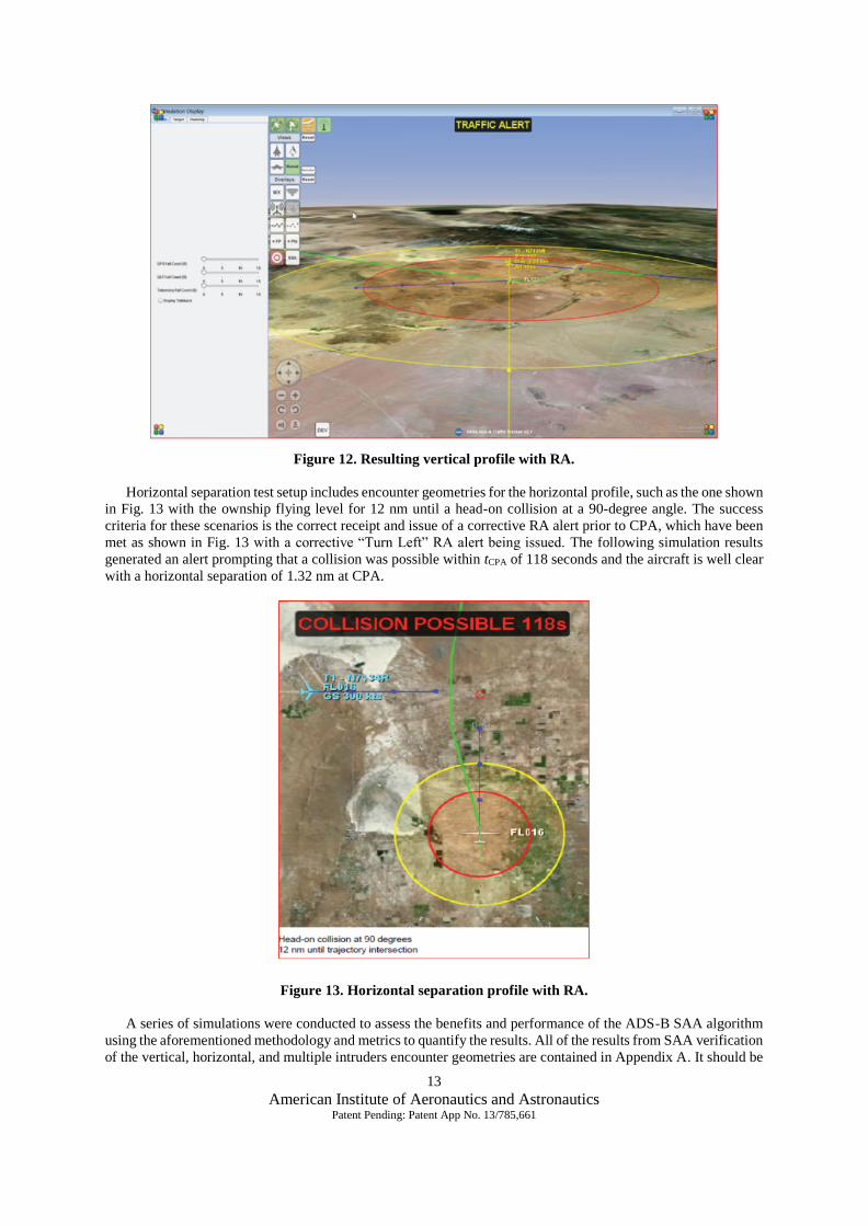
These scenarios are evaluated to the success criteria of the correct receipt and issue of a corrective RA alert
prior to CPA, which have been met as shown in Fig. 12 with a corrective “Descend” RA alert being issued and a
CPA of 0.04 nm (243 ft) when following the SAA guidance (depicted as a green trajectory change path). The
following simulation results (Fig. 12) show the aircraft is well clear with a nominal separation of +006 (600 ft) of
the intruder in the vertical dimension at the CPA.
13
American Institute of Aeronautics and Astronautics Patent Pending: Patent App No. 13/785,661
Figure 12. Resulting vertical profile with RA.
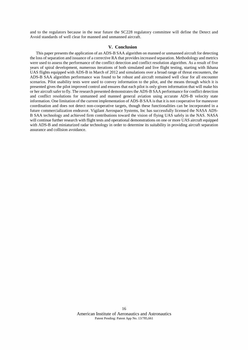
Horizontal separation test setup includes encounter geometries for the horizontal profile, such as the one shown
in Fig. 13 with the ownship flying level for 12 nm until a head-on collision at a 90-degree angle. The success
criteria for these scenarios is the correct receipt and issue of a corrective RA alert prior to CPA, which have been
met as shown in Fig. 13 with a corrective “Turn Left” RA alert being issued. The following simulation results
generated an alert prompting that a collision was possible within tCPA of 118 seconds and the aircraft is well clear
with a horizontal separation of 1.32 nm at CPA.
Figure 13. Horizontal separation profile with RA.
A series of simulations were conducted to assess the benefits and performance of the ADS-B SAA algorithm
using the aforementioned methodology and metrics to quantify the results. All of the results from SAA verification
of the vertical, horizontal, and multiple intruders encounter geometries are contained in Appendix A. It should be

14
American Institute of Aeronautics and Astronautics Patent Pending: Patent App No. 13/785,661
noted that the metrics depicted in Fig. 8 were verified throughout each of the encounter geometries and all of the
aforementioned capabilities were properly illustrated on the ADS-B SAA display. Then, these aspects can be
refined through pilot UX testing as mentioned in the previous section, taking into account the pilot response times
and pilot maneuvers in order to evaluate which capabilities need improvement as well as the accuracy of the model
in simulating the six-degrees-of-freedom of aircraft motion.
C. Live Validation Testing With the display refined to the satisfaction of various pilots at NASA AFRC and optimal SAA alerting
performance verified in a simulation environment, the next stage in this process would be validation testing. This
section will cover the validation testing conducted on a live aircraft flying avoidance maneuvers in order to ensure
sufficient algorithm performance and practical hardware installation.
1. Test Aircraft Platform
The test vehicle platform used for system validation testing was a Cessna 172 (N909ED) (Cessna Aircraft
Company, Wichita, Kansas) (Fig. 14). This test platform was selected as one of the most popular general aviation
aircraft. The Freeflight ADS-B capable XVR 978 was installed in the aft bay. The ADS-B transceiver was installed
on the Cessna per the ADS-B Interface Control Document (ICD)9 with the primary purpose of complying with
the design requirements for ADS-B Out using Advisory Circular AC-20-165A3 and for ADS-B In using Advisory
Circular AC-20-172A.10
Figure 14. Cessna 172 manned vehicle.
2. Flight Testing On August 3, 2015, the Cessna flew a training mission with an instructor pilot, and the ADS-B In surveillance
data were recorded. During flight operations it is necessary to convey information regarding the aircraft that pose
traffic threats as well as the information necessary to navigate the ownship. The ADS-B SAA system was adapted
for use in a UAS or general aviation aircraft designed for ADS-B traffic information and alerting to provide
increased situational awareness and self-separation. The test objectives to validate a proof-of-concept flight of the
display system were successfully demonstrated. The flight data shown in Fig. 15 indicates a total traffic count of
two surveillance targets. Two targets, (T1) and the NASA 7 aircraft (T2), were detected and tracked in real-time
as surveillance targets. In general, the flight demonstration validated that the system receives and displays, as
shown in Fig. 15, the following traffic information for targets of opportunity:
Relative horizontal position,
Ground speed,
Directionality (heading or track angle),
Pressure altitude of airborne traffic relative to ownship,
Vertical trend of airborne traffic,
Air/ground status of other aircraft,
Flight ID (ICAO code) of N909ED, NASA 7.

15
American Institute of Aeronautics and Astronautics Patent Pending: Patent App No. 13/785,661
Figure 15. ADS-B In traffic from August 3, 2015.
3. Results
The ADS-B SAA performance was evaluated for intruding aircraft within 1 mile along track separation. The
ADS-B SAA display is depicted in Fig. 16, with runways and taxiways, and ADS-B/TIS-B traffic on a plan
view (God's-Eye view) relative to the ownship and a collision alert advisory. In general, the flight demonstration
validated that the system receives and displays the intruder information for targets of opportunity. Nominal
trajectory propagation data based on ADS-B trajectory models were generated, and a collision advisory alert
was displayed. The SAA algorithm detected a predicted trajectory that created a loss of safe separation with the
ownship (Fig. 16) and generated an alert prompting that a collision was possible within a tCPA of 10 seconds.
Figure 16. Collision alert from August 3, 2015.
In the framework of the flight tests, simulations, and usabilty test results, the Stratway algorithm and software
using ADS-B surveillance state data has been shown to effectively maintain a safe separation distance well
clear of the aircraft in real-time. This information can be useful to both the commercialization of the technology
16
American Institute of Aeronautics and Astronautics Patent Pending: Patent App No. 13/785,661
and to the regulators because in the near future the SC228 regulatory committee will define the Detect and
Avoid standards of well clear for manned and unmanned aircraft.
V. Conclusion
This paper presents the application of an ADS-B SAA algorithm on manned or unmanned aircraft for detecting
the loss of separation and issuance of a corrective RA that provides increased separation. Methodology and metrics
were used to assess the performance of the conflict detection and conflict resolution algorithm. As a result of five
years of spiral development, numerous iterations of both simulated and live flight testing, starting with Ikhana
UAS flights equipped with ADS-B in March of 2012 and simulations over a broad range of threat encounters, the
ADS-B SAA algorithm performance was found to be robust and aircraft remained well clear for all encounter
scenarios. Pilot usability tests were used to convey information to the pilot, and the means through which it is
presented gives the pilot improved control and ensures that each pilot is only given information that will make his
or her aircraft safer to fly. The research presented demonstrates the ADS-B SAA performance for conflict detection
and conflict resolutions for unmanned and manned general aviation using accurate ADS-B velocity state
information. One limitation of the current implementation of ADS-B SAA is that it is not cooperative for maneuver
coordination and does not detect non-cooperative targets, though these functionalities can be incorporated in a
future commercialization endeavor. Vigilant Aerospace Systems, Inc has successfully licensed the NASA ADS-
B SAA technology and achieved firm contributions toward the vision of flying UAS safely in the NAS. NASA
will continue further research with flight tests and operational demonstrations on one or more UAS aircraft equipped
with ADS-B and miniaturized radar technology in order to determine its suitability in providing aircraft separation
assurance and collision avoidance.
17
American Institute of Aeronautics and Astronautics Patent Pending: Patent App No. 13/785,661
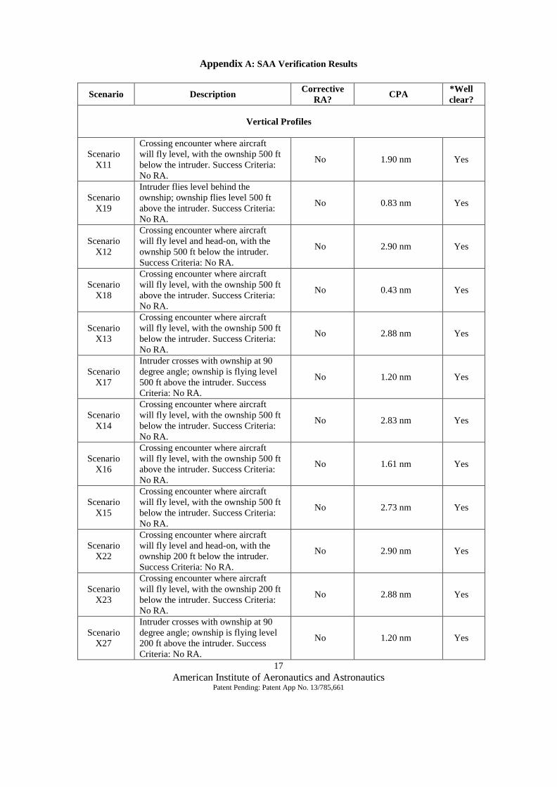
Appendix A: SAA Verification Results
Scenario Description Corrective
RA? CPA
*Well
clear?
Vertical Profiles
Scenario
X11
Crossing encounter where aircraft
will fly level, with the ownship 500 ft
below the intruder. Success Criteria:
No RA.
No 1.90 nm Yes
Scenario
X19
Intruder flies level behind the
ownship; ownship flies level 500 ft
above the intruder. Success Criteria:
No RA.
No 0.83 nm Yes
Scenario
X12
Crossing encounter where aircraft
will fly level and head-on, with the
ownship 500 ft below the intruder.
Success Criteria: No RA.
No 2.90 nm Yes
Scenario
X18
Crossing encounter where aircraft
will fly level, with the ownship 500 ft
above the intruder. Success Criteria:
No RA.
No 0.43 nm Yes
Scenario
X13
Crossing encounter where aircraft
will fly level, with the ownship 500 ft
below the intruder. Success Criteria:
No RA.
No 2.88 nm Yes
Scenario
X17
Intruder crosses with ownship at 90
degree angle; ownship is flying level
500 ft above the intruder. Success
Criteria: No RA.
No 1.20 nm Yes
Scenario
X14
Crossing encounter where aircraft
will fly level, with the ownship 500 ft
below the intruder. Success Criteria:
No RA.
No 2.83 nm Yes
Scenario
X16
Crossing encounter where aircraft
will fly level, with the ownship 500 ft
above the intruder. Success Criteria:
No RA.
No 1.61 nm Yes
Scenario
X15
Crossing encounter where aircraft
will fly level, with the ownship 500 ft
below the intruder. Success Criteria:
No RA.
No 2.73 nm Yes
Scenario
X22
Crossing encounter where aircraft
will fly level and head-on, with the
ownship 200 ft below the intruder.
Success Criteria: No RA.
No 2.90 nm Yes
Scenario
X23
Crossing encounter where aircraft
will fly level, with the ownship 200 ft
below the intruder. Success Criteria:
No RA.
No 2.88 nm Yes
Scenario
X27
Intruder crosses with ownship at 90
degree angle; ownship is flying level
200 ft above the intruder. Success
Criteria: No RA.
No 1.20 nm Yes

18
American Institute of Aeronautics and Astronautics Patent Pending: Patent App No. 13/785,661
Scenario Description Corrective
RA? CPA
*Well
clear?
Scenario
X24
Crossing encounter where aircraft
will fly level, with the ownship 200 ft
below the intruder. Success Criteria:
No RA.
No 2.83 nm Yes
Scenario
X26
Crossing encounter where aircraft
will fly level, with the ownship 200 ft
above the intruder. Success Criteria:
No RA.
No 1.61 nm Yes
Scenario
X25
Crossing encounter where aircraft
will fly level, with the ownship 200 ft
below the intruder. Success Criteria:
No RA.
No 2.73 nm Yes
Scenario
X29
Intruder flies level behind the
ownship; ownship flies level 200 ft
above the intruder. Success Criteria:
Corrective RA.
Yes
Type:
Descend
1.21 nm Yes
Scenario
X28
Intruder crosses with ownship from
behind at 45 degree angle; ownship
flies level 200 ft above the intruder.
Success Criteria: Corrective RA.
Yes
Type:
Descend
0.44 nm Yes
Scenario
X11A
Crossing encounter where aircraft
will fly level and head-on with zero
vertical separation. Success Criteria:
Corrective RA.
Yes
Type:
Descend
0.04 nm Yes
Scenario
X19A
Crossing encounter where aircraft
will fly level and head-on with zero
vertical separation. Success Criteria:
Corrective RA.
Yes
Type:
Descend
0.02 nm Yes
Scenario
X16A
Crossing encounter where aircraft
will fly level and head-on with zero
vertical separation. Success Criteria:
Corrective RA.
Yes
Type:
Descend
0.25 nm Yes
Scenario
X22A
Crossing encounter where aircraft
will fly level and head-on with zero
vertical separation. Success Criteria:
Corrective RA.
Yes
Type:
Descend
0.49 nm Yes
Scenario
X27A
Crossing encounter where aircraft
will fly level and head-on with zero
vertical separation. Success Criteria:
Corrective RA.
Yes
Type:
Descend
0.10 nm Yes
Scenario
X25A
Crossing encounter where aircraft
will fly level and head-on with zero
vertical separation. Success Criteria:
Corrective RA.
Yes
Type:
Descend
0.21 nm Yes
Scenario
X11B
Crossing encounter where aircraft
will fly level and head-on with
ownship 200 ft above the intruder.
Success Criteria: Corrective RA.
Yes
Type:
Climb
0.04 nm Yes
Scenario
X19B
Crossing encounter where aircraft
will fly level and head-on with
ownship 200 ft above the intruder.
Success Criteria: Corrective RA.
Yes
Type:
Climb
0.02 nm Yes

19
American Institute of Aeronautics and Astronautics Patent Pending: Patent App No. 13/785,661
Scenario Description Corrective
RA? CPA
*Well
clear?
Scenario
X16B
Crossing encounter where aircraft
will fly level and head-on with
ownship 200 ft above the intruder.
Success Criteria: Corrective RA.
Yes
Type:
Climb
0.25 nm Yes
Scenario
X22B
Crossing encounter where aircraft
will fly level and head-on with
ownship 200 ft above the intruder.
Success Criteria: Corrective RA.
Yes
Type:
Descend
0.49 nm Yes
Scenario
X27B
Crossing encounter where aircraft
will fly level and head-on with
ownship 200 ft above the intruder.
Success Criteria: Corrective RA.
Yes
Type:
Climb
0.10 nm Yes
Scenario
X25B
Crossing encounter where aircraft
will fly level and head-on with
ownship 200 ft above the intruder.
Success Criteria: Corrective RA.
Yes
Type:
Climb
0.11 nm Yes
Scenario
X11C
Crossing encounter where aircraft
will fly level and head-on with
ownship 200 ft below the intruder.
Success Criteria: Corrective RA.
Yes
Type:
Descend
0.04 nm Yes
Scenario
X19C
Crossing encounter where aircraft
will fly level and head-on with
ownship 200 ft below the intruder.
Success Criteria: Corrective RA.
Yes
Type:
Descend
0.02 nm Yes
Scenario
X16C
Crossing encounter where aircraft
will fly level and head-on with
ownship 200 ft below the intruder.
Success Criteria: Corrective RA.
Yes
Type:
Descend
0.25 nm Yes
Scenario
X22C
Crossing encounter where aircraft
will fly level and head-on with
ownship 200 ft below the intruder.
Success Criteria: Corrective RA.
Yes
Type:
Descend
0.49 nm Yes
Scenario
X27C
Crossing encounter where aircraft
will fly level and head-on with
ownship 200 ft below the intruder.
Success Criteria: Corrective RA.
Yes
Type:
Descend
0.10 nm Yes
Scenario
X25C
Crossing encounter where aircraft
will fly level and head-on with
ownship 200 ft below the intruder.
Success Criteria: Corrective RA.
Yes
Type:
Descend
0.11 nm Yes
Horizontal Profiles
Scenario 1
Head-on encounter where aircraft
will fly level and co-altitude (zero
vertical separation) with 0.5 nm of
lateral separation. vo, vi = 300 knots
Success Criteria: Corrective RA.
Yes
Type:
Turn Right
1.20 nm Yes
Scenario 2
Head-on encounter where aircraft
will fly level and co-altitude with
0.95 nm of lateral separation. vo, vi =
300 knots, Success Criteria:
Corrective RA.
Yes
Type:
Turn Right
1.18 nm Yes
20
American Institute of Aeronautics and Astronautics Patent Pending: Patent App No. 13/785,661
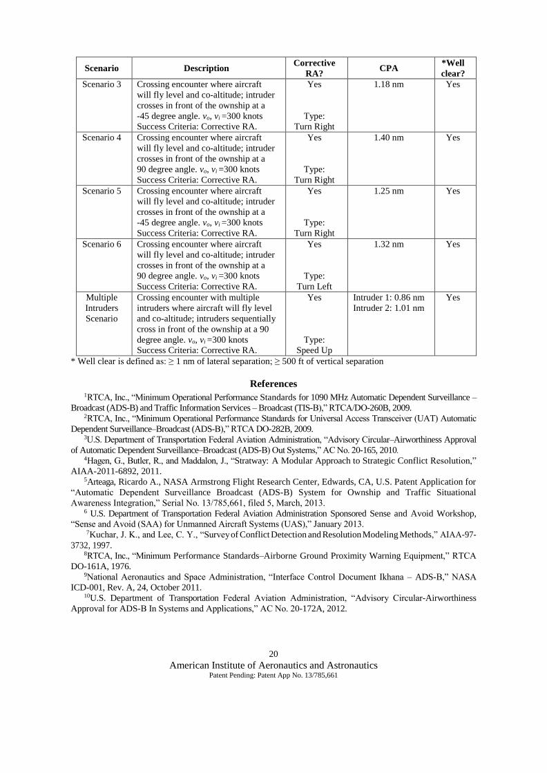
Scenario Description Corrective
RA? CPA
*Well
clear?
Scenario 3 Crossing encounter where aircraft
will fly level and co-altitude; intruder
crosses in front of the ownship at a
-45 degree angle. vo, vi =300 knots
Success Criteria: Corrective RA.
Yes
Type:
Turn Right
1.18 nm Yes
Scenario 4 Crossing encounter where aircraft
will fly level and co-altitude; intruder
crosses in front of the ownship at a
90 degree angle. vo, vi =300 knots
Success Criteria: Corrective RA.
Yes
Type:
Turn Right
1.40 nm Yes
Scenario 5 Crossing encounter where aircraft
will fly level and co-altitude; intruder
crosses in front of the ownship at a
-45 degree angle. vo, vi =300 knots
Success Criteria: Corrective RA.
Yes
Type:
Turn Right
1.25 nm Yes
Scenario 6 Crossing encounter where aircraft
will fly level and co-altitude; intruder
crosses in front of the ownship at a
90 degree angle. vo, vi =300 knots
Success Criteria: Corrective RA.
Yes
Type:
Turn Left
1.32 nm Yes
Multiple
Intruders
Scenario
Crossing encounter with multiple
intruders where aircraft will fly level
and co-altitude; intruders sequentially
cross in front of the ownship at a 90
degree angle. vo, vi =300 knots
Success Criteria: Corrective RA.
Yes
Type:
Speed Up
Intruder 1: 0.86 nm
Intruder 2: 1.01 nm
Yes
* Well clear is defined as: ≥ 1 nm of lateral separation; ≥ 500 ft of vertical separation
References 1RTCA, Inc., “Minimum Operational Performance Standards for 1090 MHz Automatic Dependent Surveillance –
Broadcast (ADS-B) and Traffic Information Services – Broadcast (TIS-B),” RTCA/DO-260B, 2009. 2RTCA, Inc., “Minimum Operational Performance Standards for Universal Access Transceiver (UAT) Automatic
Dependent Surveillance–Broadcast (ADS-B),” RTCA DO-282B, 2009. 3U.S. Department of Transportation Federal Aviation Administration, “Advisory Circular–Airworthiness Approval
of Automatic Dependent Surveillance–Broadcast (ADS-B) Out Systems,” AC No. 20-165, 2010. 4Hagen, G., Butler, R., and Maddalon, J., “Stratway: A Modular Approach to Strategic Conflict Resolution,”
AIAA-2011-6892, 2011. 5Arteaga, Ricardo A., NASA Armstrong Flight Research Center, Edwards, CA, U.S. Patent Application for
“Automatic Dependent Surveillance Broadcast (ADS-B) System for Ownship and Traffic Situational
Awareness Integration,” Serial No. 13/785,661, filed 5, March, 2013. 6 U.S. Department of Transportation Federal Aviation Administration Sponsored Sense and Avoid Workshop,
“Sense and Avoid (SAA) for Unmanned Aircraft Systems (UAS),” January 2013.
7Kuchar, J. K., and Lee, C. Y., “Survey of Conflict Detection and Resolution Modeling Methods,” AIAA-97-
3732, 1997. 8RTCA, Inc., “Minimum Performance Standards–Airborne Ground Proximity Warning Equipment,” RTCA
DO-161A, 1976. 9National Aeronautics and Space Administration, “Interface Control Document Ikhana – ADS-B,” NASA
ICD-001, Rev. A, 24, October 2011. 10U.S. Department of Transportation Federal Aviation Administration, “Advisory Circular-Airworthiness
Approval for ADS-B In Systems and Applications,” AC No. 20-172A, 2012.