application of compact optical duplicate system as...
TRANSCRIPT

Application of Compact Optical Duplicate System as a Multi-beam Generation Device for Satellite–Ground
Laser Communications
Tomoko Nakayama Yoshihisa Takayama Chiemi Fujikawa School of Engineering Wireless Network Research Institute School of Engineering Tokai Univ. NICT Tokai Univ. Kanagawa, Japan Tokyo, Japan Kanagawa, Japan [email protected] Eriko Watanabe Kashiko Kodate Center for Frontier Science and Engineering Professor Emeritus UEC JWU Tokyo, Japan Tokyo, Japan
Abstract—Satellite-ground laser communication has been of
particular interest because of increase in the quantity of data exchanged between satellites and the ground. It is necessary to improve the quality of data communication, because laser communication is vulnerable to air fluctuation. This paper reports on a simulation conducted to reduce the efficiency loss due to air fluctuations. The simulation used data from a beam transmission experiment in the atmosphere. We propose an optical duplicate system for a multi-beam generation device for satellite–ground laser communications. This is a device that generates many reproduction images for optical computing and optical information processing, the validity of which has been proven and is widely known. This device enables more efficient miniaturization and weight saving than previous techniques, and it is flexible in terms of the number of optical beams. We designed the optical duplicate system for satellite–ground laser communications, and proved the validity of this system by simulations.
Keywords—Satellite–Ground Laser Communication; Optical Duplicate System; Air Fluctuation; Multi-Beam Generation
I. INTRODUCTION Recently, space optical communications have attracted attention
because of the increased demand for data volume transfer between
artificial satellites and ground stations for media broadcasting, GPS,
positioning, earth observation, and space observation [1]. Space
laser communications use high-frequency subcarriers, and because
the wavelength is short and diffraction is small, even if the diameter
of an antenna is small, propagation loss and interference between
systems can be suppressed. Moreover, the frequency band for
optical communications is presently not subject to international
regulations; therefore, frequency resources can be utilized without
prior authorization.
However, in order to improve the quality of modulated laser data
communications, reducing the influence of air fluctuation is of
primary importance. That is, degradation of signal quality and
intensity due to air fluctuation must be reduced. In the past, (a)
wavefront correction of light according to the influence of
atmospheric distortion, and (b) method for averaging effect of light
intensity by stacking multi-beams to compensate for the influence of
atmospheric distortion have been examined [2].
In this paper, we focus on a method for intensity averaging effect.
Although methods (1) and (2), which are shown in Table 1, have
been proposed as for multi-beam generation, which is key to any
averaging technique, they have not been established in practice.
Thus, a small, lightweight, and highly efficient technique is still
sought after.
Through a numerical analysis, we demonstrated that the
averaging effect for reducing air fluctuation can be achieved by
superposing multi-beam with spatial division of laser beam intensity
in a simulated medium-distance propagation experiment in the
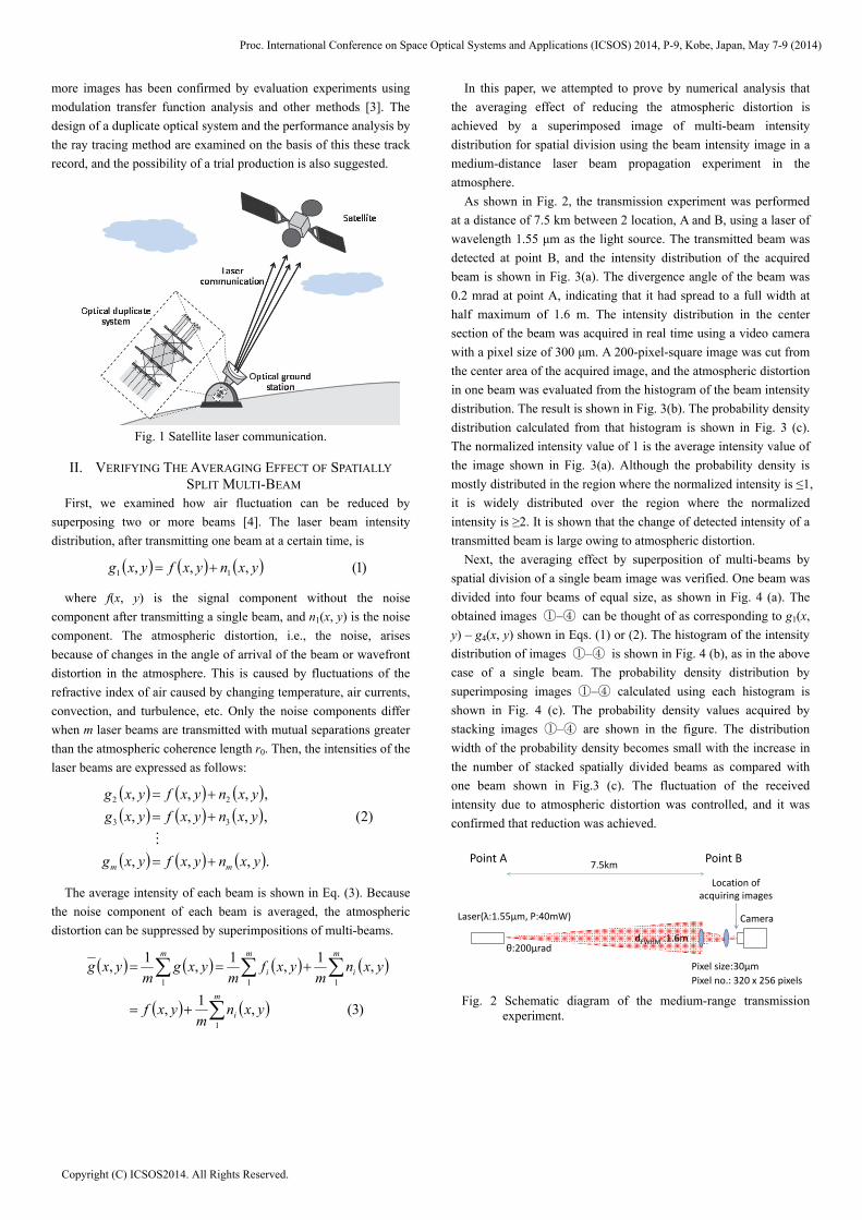
atmosphere. Based on this result, as shown in Fig. 1, we propose a
duplicate system as a spatial division device with multiple output
beam can be adapted to an established optical satellite–ground
station. The system is small and lightweight, and its number of
beam branches is variable branches.
A duplicate optical system proposed for beam generation device
was built in 2003 by the present authors as an image input device
for the parallel optical operation of a hybrid face recognition system
(optical computer), which was the first optical system of its type to
be put to practical use. The highly efficient formation of two or
Proc. International Conference on Space Optical Systems and Applications (ICSOS) 2014, P-9, Kobe, Japan, May 7-9 (2014)
Copyright (C) ICSOS2014. All Rights Reserved.
more images has been confirmed by evaluation experiments using
modulation transfer function analysis and other methods [3]. The
design of a duplicate optical system and the performance analysis by
the ray tracing method are examined on the basis of this these track
record, and the possibility of a trial production is also suggested.
Fig. 1 Satellite laser communication.
II. VERIFYING THE AVERAGING EFFECT OF SPATIALLY
SPLIT MULTI-BEAM First, we examined how air fluctuation can be reduced by
superposing two or more beams [4]. The laser beam intensity
distribution, after transmitting one beam at a certain time, is
)1(,,, 11 yxnyxfyxg
where f(x, y) is the signal component without the noise
component after transmitting a single beam, and n1(x, y) is the noise
component. The atmospheric distortion, i.e., the noise, arises
because of changes in the angle of arrival of the beam or wavefront
distortion in the atmosphere. This is caused by fluctuations of the
refractive index of air caused by changing temperature, air currents,
convection, and turbulence, etc. Only the noise components differ
when m laser beams are transmitted with mutual separations greater
than the atmospheric coherence length r0. Then, the intensities of the
laser beams are expressed as follows:
.,,,
)2(,,,,
,,,,
33
22
yxnyxfyxg
yxnyxfyxg
yxnyxfyxg
mm
The average intensity of each beam is shown in Eq. (3). Because
the noise component of each beam is averaged, the atmospheric
distortion can be suppressed by superimpositions of multi-beams.
)3(,1
,
,1
,1
,1
,
1
111
m
i
m
i
m
i
m
yxnm
yxf
yxnm
yxfm
yxgm
yxg
In this paper, we attempted to prove by numerical analysis that
the averaging effect of reducing the atmospheric distortion is
achieved by a superimposed image of multi-beam intensity
distribution for spatial division using the beam intensity image in a
medium-distance laser beam propagation experiment in the
atmosphere.
As shown in Fig. 2, the transmission experiment was performed
at a distance of 7.5 km between 2 location, A and B, using a laser of
wavelength 1.55 μm as the light source. The transmitted beam was
detected at point B, and the intensity distribution of the acquired
beam is shown in Fig. 3(a). The divergence angle of the beam was
0.2 mrad at point A, indicating that it had spread to a full width at
half maximum of 1.6 m. The intensity distribution in the center
section of the beam was acquired in real time using a video camera
with a pixel size of 300 μm. A 200-pixel-square image was cut from
the center area of the acquired image, and the atmospheric distortion
in one beam was evaluated from the histogram of the beam intensity
distribution. The result is shown in Fig. 3(b). The probability density
distribution calculated from that histogram is shown in Fig. 3 (c).
The normalized intensity value of 1 is the average intensity value of
the image shown in Fig. 3(a). Although the probability density is
mostly distributed in the region where the normalized intensity is ≤1,
it is widely distributed over the region where the normalized
intensity is ≥2. It is shown that the change of detected intensity of a
transmitted beam is large owing to atmospheric distortion.
Next, the averaging effect by superposition of multi-beams by
spatial division of a single beam image was verified. One beam was
divided into four beams of equal size, as shown in Fig. 4 (a). The
obtained images ①–④ can be thought of as corresponding to g1(x,
y) – g4(x, y) shown in Eqs. (1) or (2). The histogram of the intensity
distribution of images ①–④ is shown in Fig. 4 (b), as in the above
case of a single beam. The probability density distribution by
superimposing images ①–④ calculated using each histogram is
shown in Fig. 4 (c). The probability density values acquired by
stacking images ①–④ are shown in the figure. The distribution
width of the probability density becomes small with the increase in
the number of stacked spatially divided beams as compared with
one beam shown in Fig.3 (c). The fluctuation of the received
intensity due to atmospheric distortion was controlled, and it was
confirmed that reduction was achieved.
Fig. 2 Schematic diagram of the medium-range transmission
experiment.
Point A Point B7.5km
Laser(λ:1.55μm, P:40mW) Camera
Pixel size:30μm
Pixel no.: 320 x 256 pixels
θ:200μraddFWHM :1.6m
Location of acquiring images
Proc. International Conference on Space Optical Systems and Applications (ICSOS) 2014, P-9, Kobe, Japan, May 7-9 (2014)
Copyright (C) ICSOS2014. All Rights Reserved.

(a) (b)
(c)
Fig. 3 (a) Image of one beam obtained in the beam transmission
experiment in the atmosphere and (b) intensity distribution
of a single. (c) Probability density distributions of the single
beam. The intensity is normalized by the average value.
(a)
(b)
(c)
Fig. 4 (a) Single beam divided into four beams and (b) intensity
distribution of each of the four beams. (c) Probability
density distributions of spatially superimposed beams. The
intensity is normalized by the each average value.
III. COMPACT OPTICAL DUPLICATE SYSTEM FOR A MULTI-
BEAM GENERATION DEVICE FOR SPACE LASER COMUNICATIONS
A. Principle of optical duplicate system An arrangement of an optical duplicate system is shown in Fig.5.
The incident wavefront is split by array lens AL1 into a number of
wavefronts equal to the number of lenses in the array. Each divided
beam enters lens L1. AL1 and L1 form the focal system, and the
beams split by AL1 are collimated in different directions and
overlapped on the input plane (IP). When the transparent pattern is
incident on the IP, each collimated beam forms a Fourier transform
on the focal plane of lens L2. A number of Fourier-transformed
images equal to the number of lenses constituting the AL are
generated. The images are Fourier-transformed again by array lens
AL2, and the pattern displayed on the IP is duplicated on the
200pixels
200pixels
0 1 2 3 40
2000
4000
6000
Normalized intensityN
um
ber
of pix
cels
[a.
u.] image01
1 beam
100pixels
① ②
③ ④
100pixels
0 1 2 3 40
250
500
750
1000
1250
Normalized intensity
Num
ber
of pi
xels
[a.
u.] image01
0 1 2 3 40
250
500
750
1000
1250
Normalized intensity
Num
ber
of pi
xels
[a.
u.] image02
0 1 2 3 40
250
500
750
1000
1250
Normalized intensity
Num
ber
of pi
xels
[a.
u.] image03
0 1 2 3 40
250
500
750
1000
1250
Normalized intensity
Num
ber
of pi
xels
[a.
u.] image04
① ②
③ ④
0 0.25 0.5 0.75 1 1.25 1.5 1.75 20
0.25
0.5
0.75
1
1.25
1.5
Normalized intensity
Pro
babi
lity
densi
ty
①①+②①+②+③①+②+③+④
0 0.25 0.5 0.75 1 1.25 1.5 1.75 20
0.25
0.5
0.75
1
1.25
1.5
Normalized intensity
Pro
babi
lity
densi
ty
Proc. International Conference on Space Optical Systems and Applications (ICSOS) 2014, P-9, Kobe, Japan, May 7-9 (2014)
Copyright (C) ICSOS2014. All Rights Reserved.

output plane (OP), which is the focal plane of AL2 [5].
Because the position of the lens comprising AL1 and AL2
corresponds to the position of a duplicate image, the position of a
duplicate image can be changed by changing the position of each
lens in AL1 and AL2. A Fourier-transformed image and a duplicate
image can be simultaneously obtained on the same plane by
adjusting the focal length of each lens constituting AL1 and AL2.
That is, different designs corresponding to various array lenses are
possible. Moreover, an additional process using a duplicate image as
an input image, i.e., a cascade process, is easy to perform because
the output plane crosses the optical axes of AL1, L1, L2, and AL2.
Fig. 5 Optical duplicate system.
B. Design of the optical duplicate system for a multi-beam generator
The numerical values required for the design of an optical
duplicate system were calculated using geometric optics. The size di
of the input plane that can input the beam to be duplicated is
calculated from the following:
. (4)
The magnification of a duplicate image is calculated from the
following:
. (5)
The length of one side of an output beam do is calculated from the
following:
. (6)
The distance between output beams po is calculated from the
following:
, (7)
where, d1 is the diameter of the lenses in AL1, and f1, f2, f3, and f4
are the focal lengths of AL1, L1, L2, and AL2, respectively. The
number of duplicate beams is the same as the number of lenses in
AL1 and AL2.
The designed optical duplicate system will be used to split 1
beam into 4 beams with the following design condition,and it is
assumed that the system will be installed in the telescope at the
National Institute of Information and Communications Technology
(NICT) ground station for space laser communication. Further, it is
assumed that the system will be used in urban areas, with a 10×
telescope, and a predetermined distance between output beams. L1
and L2 were of the same specifications. For the case of entering the
collimated beam, in order to suppress the spherical aberration of
each lens, the incidence side of a lens was made convex. For the
same reason, when a collimated beam is output, the output side of
lens is also convex. In order to condense an incident beam
efficiently, AL1 and AL2 were from 2 × 2 square lenses; however,
since the incident beam was circular, AL2 was made circular. Only
the domain of 2 × 2 square lenses contributes to the output of a
beam. [Design condition]
· Number of output beam: 4 · Distance between output beams: po = 3 mm · Length of one side of an output beam: do = 1.5 mm · Wavelength of the input beam: 1.55 m · Diameter of the input beam: < 10 mm · Form of the lenses in AL1 and AL2: square · Form of AL1 and AL2: circular · Material of AL1, AL2, L1, and L2: NBK-7 (index: n = 1.50) · Thickness of AL1, AL2, L1, and L2: 5 mm · Length of one side of a lens in AL1: d1 = 3 mm · Focal length: f1 = 50 mm,f2 = f3 = 100 mm,f4 = 25 mm
C. Examination of the optical duplicate system for space
laser communication with a compact multi-beam generator by simulation
As summarized in Table 1, the conventional multi-beam
generation method for space laser communications includes (1)
installing the optical system composing beam splitters and mirrors
with reflectance distribution in the telescope of the existing ground
station, and (2) producing a new system comprising a laser and a
telescope for projecting multi-beams. It is necessary to produce a
new system that allows for changing the number of beams from
each element comprising the optical system. However, the optical
duplicate system proposed in this paper can be miniaturized
independently of the number of beam branches by controlling the
input pattern without changing the composition of each element. It
is necessary to change the output beam size and the interval between
output beams. Because the degree of atmospheric distortion depends
on the position of a ground station and the time taken for
communication with a satellite, the optical duplicate system with an
easily controlled number of beams is useful in space laser
communication.
f4f1 f3f2 f3f2f1
f4
AL1 AL2L1 L2
Input imageDuplicate image
Input plane Output plane
F
Fourierimage
F
F
F
F
F
121 ffddi
34 ff
31421 ffffddo
231 ffdpo
Proc. International Conference on Space Optical Systems and Applications (ICSOS) 2014, P-9, Kobe, Japan, May 7-9 (2014)
Copyright (C) ICSOS2014. All Rights Reserved.
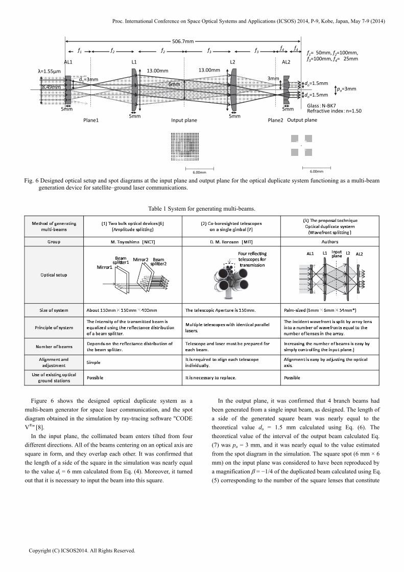
Fig. 6 Designed optical setup and spot diagrams at the input plane and output plane for the optical duplicate system functioning as a multi-beam
generation device for satellite–ground laser communications.
Table 1 System for generating multi-beams.
Figure 6 shows the designed optical duplicate system as a
multi-beam generator for space laser communication, and the spot
diagram obtained in the simulation by ray-tracing software "CODE
V®" [8].
In the input plane, the collimated beam enters tilted from four
different directions. All of the beams centering on an optical axis are
square in form, and they overlap each other. It was confirmed that
the length of a side of the square in the simulation was nearly equal
to the value di = 6 mm calculated from Eq. (4). Moreover, it turned
out that it is necessary to input the beam into this square.
In the output plane, it was confirmed that 4 branch beams had
been generated from a single input beam, as designed. The length of
a side of the generated square beam was nearly equal to the
theoretical value do = 1.5 mm calculated using Eq. (6). The
theoretical value of the interval of the output beam calculated Eq.
(7) was po = 3 mm, and it was nearly equal to the value estimated
from the spot diagram in the simulation. The square spot (6 mm × 6
mm) on the input plane was considered to have been reproduced by
a magnification = −1/4 of the duplicated beam calculated using Eq.
(5) corresponding to the number of the square lenses that constitute
6.00mm 6.00mm
AL2
3mm
8.49mm
L1
5mm
do=1.5mm
do=1.5mm
f4
Output plane
5mm
5mm 5mm
Glass:N‐BK7Refractive index:n=1.50
Input plane
po=3mm
f1 f2f4
f1= 50mm, f2=100mm,f3=100mm, f4= 25mm
f3f2 f3
6mm
13.00mm
d1=3mm
Plane1
AL1 L2
13.00mmλ=1.55μm
Plane2
506.7mm
Proc. International Conference on Space Optical Systems and Applications (ICSOS) 2014, P-9, Kobe, Japan, May 7-9 (2014)
Copyright (C) ICSOS2014. All Rights Reserved.

the AL.
As mentioned above, the optical duplicate system can flexibly
control the number of beams according to the number of branch
devices inserted image in the input plane without changing the
specifications of the array lens or its arrangement. However, the
output beam interval becomes small when inputting a beam onto the
input plane and increasing the number of output beams. In order to
reduce the influences of atmospheric distortion by multi-beam
transmission, the interval between beam needs to be longer than the
coherence length of air. This interval can be adjusted by changing
the magnification of the telescope arranged behind the optical
duplicate system.
IV. CONCLUSION
As a multi-beam generator for reducing the influence of atmospheric distortion in satellite–ground laser communications, a small and lightweight optical duplicate system was newly proposed. We proved that the averaging effect reduced atmospheric distortion by superimposing multi-beams in space through the calculation of probability density distributions using beams obtained in transmission experiments in the atmosphere. On the basis of this result, the small optical duplicate system was proposed as a spatial division multi-beam generator that can flexibly control the number of output beams. Furthermore, it is assumed that an optical duplicate system is to be installed in the telescope of the ground station of NICT after determining the size and the output pattern of the output beam, the size of the array lens, the lenses constituting the optical duplicate system, the arrangement of the optical system, etc., and a realizable optical duplicate system was designed. In the future, we will produce a prototype optical duplicate system based on this design and prove the reduction of the atmospheric distortion using multi-beams.
REFERENCES [1] Y. Takayama, M. Toyoshima, H. Takenaka, N. Kadowaki:The
Current State and the Future Plans of the Satellite Laser Communications, IEICE TRANSACTIONS on Communications B, Vol.J94-B, No.11, pp.1443-1451 (2011).
[2] M. Toyoshima, Y. Takayama, T. Takahashi, K. Suzuki, S, Kimura, K. Takizawa, T. Kuri, W. Klaus, M. Toyoda, H. Kunimori and T. Jono: Laser beam propagation in ground-to OICETS laser communication links, the journal of space technology and science (JSTS), Vol.23, No.2, pp.30 -45 (2007).
[3] E. Watanabe, K. Kodate: An Optical Duplicate System for the Input Images by Elgraphy, Proc. of The Faculty of Science of Japan Women’s University, Vol.11, pp.71-78 (2003).
[4] T. Nakayama, Y. Takayama, C. Fujikawa, K. Kodate: Design of Compact Optical Duplicate System for Multi-Beam Generation and Application of Satellite-Ground Laser Communications, Proc. of the 9th International Conference on Optics-photonics Design & Fabrication, Itabashi, Tokyo February 12-14, pp. 155-156 (2014).
[5] K. Hamanaka, H. Nemoto, M. Oikawa, E. Okuda and T. Kishimoto: Multiple imaging and multiple Fourier transformation using planar microlens arrays, Appl. Opt. Vol.29, No.28, pp.4064-4070 (1990).
[6] M. Toyashima, K. Araki: optical branching method, JP 2001-156371 (1999).
[7] D. M. Boroson, J. J. Scozzafava, D. V. Murphy and B. S. Robinson: The Lunar Laser Communications Demonstration (LLCD), Space Mission Challenges for Information Technology, pp.23-28 (2009) IEEE.
[8] T. Nakayama, Y. Takayama, C. Fujikawa, E. Watanabe, K. Kodate: An Optical Duplicate System for Satellite-Ground Laser Communications, Proc. of The School of Engineering of Tokai University, Vol. 52, No. 2, pp.101-106 (2012).
Proc. International Conference on Space Optical Systems and Applications (ICSOS) 2014, P-9, Kobe, Japan, May 7-9 (2014)
Copyright (C) ICSOS2014. All Rights Reserved.