application of fdm rapid prototyping technology in
TRANSCRIPT
J. Novak-Marcincin et al. Primjena FDM postupka brze izrade prototipa u procesu razvoja eksperimentalne mjenjačke kutije
Tehnički vjesnik 19, 3(2012), 689-694 689
ISSN 1330-3651 UDC/UDK 658.512.2:658.624]:62-585
APPLICATION OF FDM RAPID PROTOTYPING TECHNOLOGY IN EXPERIMENTAL GEARBOX DEVELOPMENT PROCESS Jozef Novak-Marcincin, Ludmila Novakova-Marcincinova, Jozef Barna, Miroslav Janak
Preliminary notes This paper in its theoretical part presents basic and advanced methods of Rapid Prototyping (RP) technology with a special focus on Fused Deposition Modelling (FDM) method used by authors on Faculty of Manufacturing Technologies of Technical University of Košice with a seat in Prešov (Slovakia). Principles of FDM technology and materials used for production of models and products are described. Practical part of the paper describes development process of experimental gearbox from 3D modelling of particular parts, through the realization of gearbox assembly, to application of FDM technology for production of gearbox parts and final assembly of the product. Keywords: Fused Deposition Modelling, experimental gearbox, Rapid Prototyping Primjena FDM postupka brze izrade prototipa u procesu razvoja eksperimentalne mjenjačke kutije
Prethodno priopćenje Ovaj rad u svom teorijskom dijelu prikazuje osnovne i napredne metode tehnologije brze izrade prototipa s posebnim naglaskom na modeliranje taloženjem (FDM), postupkom koji su koristili autori s Fakulteta proizvodnih tehnologija Tehničkog sveučilišta u Košicama sa sjedištem u Prešovu (Slovačka). Opisan je princip FDM postupka brze izrade prototipa i materijali koji se koriste za izradu modela i proizvoda s tim postupkom. Praktični dio ovog rada opisuje proces razvoja eksperimentalne mjenjačke kutije od 3D modeliranja pojedinih dijelova, preko realizacije montaže mjenjačke kutije, do primjene FDM postupka za proizvodnju dijelova mjenjačke kutije i konačnu montažu proizvoda. Ključne riječi: Brza izrada prototipa, eksperimentalna mjenjačka kutija, modeliranje taloženjem
1 Introduction
Rapid Prototyping presents a relatively new type of manufacturing technology that is often used for production of the automatic construction of physical objects using additive principle. Beginnings of Rapid Prototyping technology are dated in the late 1980’s when Stereolithography technology was defined as a method and a device was built for making solid objects by successive “printing” of thin layers of the ultraviolet curable material one on top of the other, what led to production of models and prototype parts. In 1986 the first company was founded which generalized and commercialized such procedure, 3D Systems Inc. The term "Stereolithography" was defined in the U.S. Patent 4,575,330, entitled "Apparatus for Production of Three-Dimensional Objects by Stereolithography", issued on March 11, 1986. Today, there is a much wider range of Rapid Prototyping methods that are used to manufacture the models, parts or final products. Before the application of Rapid Prototyping technology we must handle the models of future parts while using Computer Aided Design (CAD) systems, then transform them into STL format that is further used in Rapid Prototyping devices for parts production [4]. 2 The Main Rapid Prototyping processes
While with traditional methods the prototype needed to be constructed and finished manually, rapid prototyping attitude brings the possibility of changing the necessary properties usually responding with geometrical characteristics and to simply create the new prototype on the basis of the file from the previous version. This makes
prototype creation much faster and easier. There is a multitude of experimental RP methodologies either in development or used for production by small groups of individuals, including Stereolithography (SLA), Selective Laser Sintering (SLS), Fused Deposition Modelling (FDM), Solid Ground Curing (SGC) and 3D Ink Jet printing [1].
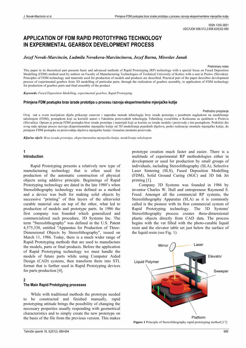
Company 3D Systems was founded in 1986 by inventor Charles W. Hull and entrepreneur Raymond S. Freed. Amongst all the commercial RP systems, the Stereolithography Apparatus (SLA) as it is commonly called is the pioneer with its first commercial system of Rapid Prototyping technology. The 3D Systems' Stereolithography process creates three-dimensional plastic objects directly from CAD data. The process begins with the vat filled with the photo-curable liquid resin and the elevator table set just below the surface of the liquid resin (see Fig. 1).
Figure 1 Principle of Stereolithography rapid prototyping method [17]
Application of FDM rapid prototyping technology in experimental gearbox development process J. Novak-Marcincin et al.
690 Technical Gazette 19, 3(2012), 689-694
The operator loads a three-dimensional CAD solid model file into the system. Supports are designed to stabilize the part during the building. The translator converts the CAD data into a STL file. The control unit slices the model and support into a series of cross sections from 0,025 to 0,5 mm thick. The computer-controlled optical scanning system then directs and focuses the laser beam so that it solidifies a two-dimensional cross-section corresponding to the slice on the surface of the photo-curable liquid resin to a depth greater than one layer thickness. The elevator table then drops enough to cover the solid polymer with another layer of the liquid resin. A leveling wiper or vacuum blade (from Zephyr recoating system) moves across the surfaces to recoat the next layer of resin on the surface. The laser then draws the next layer [2, 17].
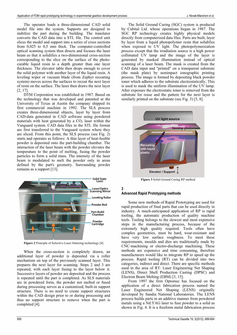
DTM Corporation was established in 1987. Based on the technology that was developed and patented at the University of Texas at Austin the company shipped its first commercial machine in 1992. The SLS process creates three-dimensional objects, layer by layer from CAD-data generated in CAD software using powdered materials with heat generated by a CO2 laser within the Vanguard system. CAD data files in the STL file format are first transferred to the Vanguard system where they are sliced. From this point, the SLS process (see Fig. 2) starts and operates as follows: A thin layer of heat-fusible powder is deposited onto the part-building chamber. The interaction of the laser beam with the powder elevates the temperature to the point of melting, fusing the powder particles to form a solid mass. The intensity of the laser beam is modulated to melt the powder only in areas defined by the part's geometry. Surrounding powder remains as a support [13].
Figure 2 Principle of Selective Laser Sintering technology [4]
When the cross-section is completely drawn, an
additional layer of powder is deposited via a roller mechanism on top of the previously scanned layer. This prepares the next layer for scanning. Steps 2 and 3 are repeated, with each layer fusing to the layer below it. Successive layers of powder are deposited and the process is repeated until the part is completed. As SLS materials are in powdered form, the powder not melted or fused during processing serves as a customized, built-in support structure. There is no need to create support structures within the CAD design prior to or during processing and thus no support structure to remove when the part is completed [4].
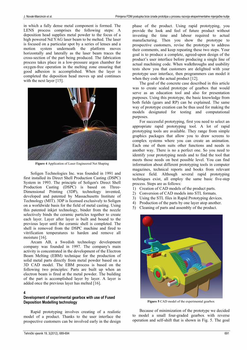
The Solid Ground Curing (SGC) system is produced by Cubital Ltd. whose operations began in 1987. The SGC RP technology creates highly physical models directly from computerized data files. Parts are built, layer by layer from a liquid photopolymer resin that solidifies when exposed to UV light. The photopolymerization process except that the irradiation source is a high power collimated UV lamp and the image of the layer is generated by masked illumination instead of optical scanning of a laser beam. The mask is created from the CAD data input and "printed" on a transparent substrate (the mask plate) by nonimpact ionographic printing process. The image is formed by depositing black powder toner which adheres to the substrate electrostatically. This is used to mask the uniform illumination of the UV lamp. After exposure the electrostatic toner is removed from the substrate for reuse and the pattern for the next layer is similarly printed on the substrate (see Fig. 3) [5, 8].
Figure 3 Solid Ground Curing RP method
3 Advanced Rapid Prototyping methods
Some new methods of Rapid Prototyping are used for rapid production of final parts that can be used directly in industry. A much-anticipated application of RP is rapid tooling, the automatic production of quality machine tools. Tooling belongs to the slowest and most expensive steps in the manufacturing process, because of the extremely high quality required. Tools often have complex geometries, must be hard, wear-resistant and have very low surface roughness. To meet these requirements, moulds and dies are traditionally made by CNC-machining or electro-discharge machining. These methods are expensive and time consuming, therefore manufacturers would like to integrate RP to speed up the process. Rapid tooling (RT) can be divided into two categories, indirect and direct. There are specific methods used in the area of RT: Laser Engineering Net Shaping (LENS), Direct Shell Production Casting (DPSC) and Electron Beam Melting (EBM) [3, 15].
From 1997 the firm Optomec has focused on the application of a direct fabrication process named the Laser Engineered Net Shaping (LENS) originally developed by Sandia National Laboratories. The LENS process builds parts in an additive manner from powdered metals using a Nd:YAG laser to fuse powder to a solid as shown in Fig. 4. It is a freeform metal fabrication process
J. Novak-Marcincin et al. Primjena FDM postupka brze izrade prototipa u procesu razvoja eksperimentalne mjenjačke kutije
Tehnički vjesnik 19, 3(2012), 689-694 691
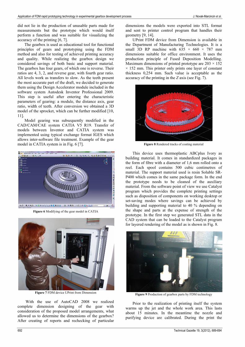
in which a fully dense metal component is formed. The LENS process comprises the following steps: A deposition head supplies metal powder to the focus of a high powered Nd:YAG laser beam to be melted. The laser is focused on a particular spot by a series of lenses and a motion system underneath the platform moves horizontally and laterally as the laser beam traces the cross-section of the part being produced. The fabrication process takes place in a low-pressure argon chamber for oxygen-free operation in the melting zone ensuring that good adhesion is accomplished. When the layer is completed the deposition head moves up and continues with the next layer [15].
Figure 4 Application of Laser Engineered Net Shaping
Soligen Technologies Inc. was founded in 1991 and
first installed its Direct Shell Production Casting (DSPC) System in 1993. The principle of Soligen's Direct Shell Production Casting (DSPC) is based on Three-Dimensional Printing (3DP), technology invented, developed and patented by Massachusetts Institute of Technology (MIT). 3DP is licensed exclusively to Soligen on a worldwide basis for the field of metal casting. Using this patented inkjet technology, binder from the nozzle selectively binds the ceramic particles together to create each layer. Layer after layer is built and bound to the previous layer until the ceramic shell is completed. The shell is removed from the DSPC machine and fired to vitrification temperatures to harden and remove all moisture [16].
Arcam AB, a Swedish technology development company was founded in 1997. The company's main activity is concentrated in the development of the Electron Beam Melting (EBM) technique for the production of solid metal parts directly from metal powder based on a 3D CAD model. The EBM process is based on the following two principles: Parts are built up when an electron beam is fired at the metal powder. The building of the part is accomplished layer by layer. A layer is added once the previous layer has melted [16]. 4 Development of experimental gearbox with use of Fused Deposition Modelling technology
Rapid prototyping involves creating of a realistic model of a product. Thanks to the user interface the prospective customers can be involved early in the design
phase of the product. Using rapid prototyping, you provide the look and feel of future product without investing the time and labour required to actual manufacturing. Then you show the prototype to prospective customers, revise the prototype to address their comments, and keep repeating these two steps. Your goal is to produce a complete, agreed-upon design of the product’s user interface before producing a single line of actual machining code. When walkthroughs and usability tests show you that customers are delighted with your prototype user interface, then programmers can model it when they code the actual product [12].
The goal of the concrete case described in this article was to create scaled prototype of gearbox that would serve as an education tool and also for presentation purposes. Using this prototype, the basic knowledge from both fields (gears and RP) can be explained. The same way of prototype creation can be thus used for making the models designated for testing and computational purposes.
For successful prototyping, first you need to select an appropriate rapid prototyping tool. A lot of rapid prototyping tools are available. They range from simple graphics packages that allow you to draw screens to complex systems where you can create an animation. Each one of them suits other functions and needs in another way. There is no a perfect one. So you need to identify your prototyping needs and to find the tool that meets those needs on best possible level. You can find information about different prototyping tools in computer magazines, technical reports and books from relevant science field. Although several rapid prototyping techniques exist, all employ the same basic five-step process. Steps are as follows: 1) Creation of CAD models of the product parts. 2) Conversion of CAD models into STL formats. 3) Using the STL files in Rapid Prototyping devices. 4) Production of the parts by one layer atop another. 5) Cleaning of parts and assembly of the product.
Figure 5 CAD model of the experimental gearbox
Because of minimization of the prototype we decided
to model a small four-graded gearbox with reverse operation and self-shift that is shown in Fig. 5. The goal
Application of FDM rapid prototyping technology in experimental gearbox development process J. Novak-Marcincin et al.
692 Technical Gazette 19, 3(2012), 689-694
did not lie in the production of unusable parts made for measurements but the prototype which would itself perform a function and was suitable for visualizing the accuracy of the printing [6, 7].
The gearbox is used as educational tool for functional principles of gears and prototyping using the FDM method and also for testing of achieved printing accuracy and quality. While realizing the gearbox design we considered savings of both basic and support material. The gearbox has four gears, of which one is reverse. Their ratios are 4, 3, 2, and reverse gear, with fourth gear ratio. All levels work as transfers to slow. As the teeth present the most accurate part of the draft, we decided to generate them using the Design Accelerator module included in the software system Autodesk Inventor Professional 2009. This step is useful after entering the characteristic parameters of gearing: a module, the distance axis, gear ratio, width of teeth. After conversion we obtained a 3D model of the sprocket, which can be further modified [10, 11].
Model gearing was subsequently modified in the CAD/CAM/CAE system CATIA V5 R19. Transfer of models between Inventor and CATIA system was implemented using typical exchange format IGES which allows inter-software file treatment. Example of the gear model in CATIA system is in Fig. 6 [7].
Figure 6 Modifying of the gear model in CATIA
Figure 7 FDM device UPrint from Dimension
With the use of AutoCAD 2008 we realized
complete dimension designing of the gear with consideration of the proposed model arrangements, what allowed us to determine the dimensions of the gearbox? After creating of reports and rechecking of particular
dimensions the models were exported into STL format and sent to printer control program that handles their geometry [9, 14].
UPrint FDM device from Dimension is available in the Department of Manufacturing Technologies. It is a small 3D RP machine with 635 × 660 × 787 mm dimensions suitable for office environment. It uses the production principle of Fused Deposition Modelling. Maximum dimensions of printed prototype are 203 × 152 × 152 mm. This printer only prints one layer of constant thickness 0,254 mm. Such value is acceptable as the accuracy of the printing in the Z axis (see Fig. 7).
Figure 8 Rendered tracks of coating material
This device uses thermoplastic ABCplus Ivory as
building material. It comes in standardized packages in the form of fibre with a diameter of 1,6 mm rolled onto a reel. Each spool contains 500 cubic centimetres of material. The support material used is resin Soluble SR-P400 which comes in the same package form. In the end the prototype needs to be cleaned of the auxiliary material. From the software point of view we use Catalyst program which provides the complete printing settings such as disposition of components on working desktop or set-saving modes where savings can be achieved by building and supporting material to 40 % depending on the shape and parts at the expense of strength of the prototype. In the first step we generated STL data in the CAD system that can be loaded to the Catalyst program for layered rendering of the model as is shown in Fig. 8.
Figure 9 Production of gearbox parts by FDM technology
Prior to the realization of printing itself the system
warms up the jet and the whole work area. This lasts about 15 minutes. In the meantime the nozzle and purifying device are calibrated. During the print the
J. Novak-Marcincin et al. Primjena FDM postupka brze izrade prototipa u procesu razvoja eksperimentalne mjenjačke kutije
Tehnički vjesnik 19, 3(2012), 689-694 693
nozzle moves over X - Y pad and works in the Z axis. Once done, it is necessary to separate the support material from the building one. In the semi-simple components the support material can be separated without any problems, because with reduced temperature it is particularly fragile (Fig. 9) [7].
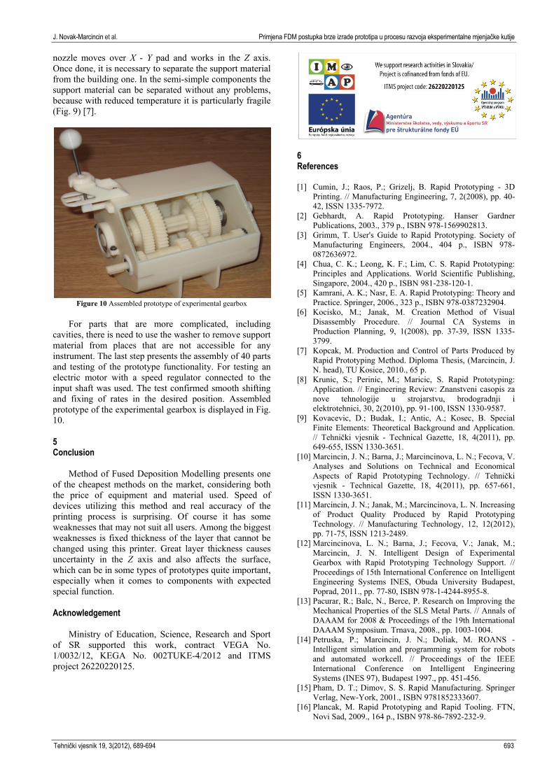
Figure 10 Assembled prototype of experimental gearbox
For parts that are more complicated, including
cavities, there is need to use the washer to remove support material from places that are not accessible for any instrument. The last step presents the assembly of 40 parts and testing of the prototype functionality. For testing an electric motor with a speed regulator connected to the input shaft was used. The test confirmed smooth shifting and fixing of rates in the desired position. Assembled prototype of the experimental gearbox is displayed in Fig. 10. 5 Conclusion
Method of Fused Deposition Modelling presents one of the cheapest methods on the market, considering both the price of equipment and material used. Speed of devices utilizing this method and real accuracy of the printing process is surprising. Of course it has some weaknesses that may not suit all users. Among the biggest weaknesses is fixed thickness of the layer that cannot be changed using this printer. Great layer thickness causes uncertainty in the Z axis and also affects the surface, which can be in some types of prototypes quite important, especially when it comes to components with expected special function. Acknowledgement
Ministry of Education, Science, Research and Sport of SR supported this work, contract VEGA No. 1/0032/12, KEGA No. 002TUKE-4/2012 and ITMS project 26220220125.
6 References [1] Cumin, J.; Raos, P.; Grizelj, B. Rapid Prototyping - 3D
Printing. // Manufacturing Engineering, 7, 2(2008), pp. 40-42, ISSN 1335-7972.
[2] Gebhardt, A. Rapid Prototyping. Hanser Gardner Publications, 2003., 379 p., ISBN 978-1569902813.
[3] Grimm, T. User's Guide to Rapid Prototyping. Society of Manufacturing Engineers, 2004., 404 p., ISBN 978-0872636972.
[4] Chua, C. K.; Leong, K. F.; Lim, C. S. Rapid Prototyping: Principles and Applications. World Scientific Publishing, Singapore, 2004., 420 p., ISBN 981-238-120-1.
[5] Kamrani, A. K.; Nasr, E. A. Rapid Prototyping: Theory and Practice. Springer, 2006., 323 p., ISBN 978-0387232904.
[6] Kocisko, M.; Janak, M. Creation Method of Visual Disassembly Procedure. // Journal CA Systems in Production Planning, 9, 1(2008), pp. 37-39, ISSN 1335-3799.
[7] Kopcak, M. Production and Control of Parts Produced by Rapid Prototyping Method. Diploma Thesis, (Marcincin, J. N. head), TU Kosice, 2010., 65 p.
[8] Krunic, S.; Perinic, M.; Maricic, S. Rapid Prototyping: Application. // Engineering Review: Znanstveni casopis za nove tehnologije u strojarstvu, brodogradnji i elektrotehnici, 30, 2(2010), pp. 91-100, ISSN 1330-9587.
[9] Kovacevic, D.; Budak, I.; Antic, A.; Kosec, B. Special Finite Elements: Theoretical Background and Application. // Tehnički vjesnik - Technical Gazette, 18, 4(2011), pp. 649-655, ISSN 1330-3651.
[10] Marcincin, J. N.; Barna, J.; Marcincinova, L. N.; Fecova, V. Analyses and Solutions on Technical and Economical Aspects of Rapid Prototyping Technology. // Tehnički vjesnik - Technical Gazette, 18, 4(2011), pp. 657-661, ISSN 1330-3651.
[11] Marcincin, J. N.; Janak, M.; Marcincinova, L. N. Increasing of Product Quality Produced by Rapid Prototyping Technology. // Manufacturing Technology, 12, 12(2012), pp. 71-75, ISSN 1213-2489.
[12] Marcincinova, L. N.; Barna, J.; Fecova, V.; Janak, M.; Marcincin, J. N. Intelligent Design of Experimental Gearbox with Rapid Prototyping Technology Support. // Proceedings of 15th International Conference on Intelligent Engineering Systems INES, Obuda University Budapest, Poprad, 2011., pp. 77-80, ISBN 978-1-4244-8955-8.
[13] Pacurar, R.; Balc, N., Berce, P. Research on Improving the Mechanical Properties of the SLS Metal Parts. // Annals of DAAAM for 2008 & Proceedings of the 19th International DAAAM Symposium. Trnava, 2008., pp. 1003-1004.
[14] Petruska, P.; Marcincin, J. N.; Doliak, M. ROANS - Intelligent simulation and programming system for robots and automated workcell. // Proceedings of the IEEE International Conference on Intelligent Engineering Systems (INES 97), Budapest 1997., pp. 451-456.
[15] Pham, D. T.; Dimov, S. S. Rapid Manufacturing. Springer Verlag, New-York, 2001., ISBN 9781852333607.
[16] Plancak, M. Rapid Prototyping and Rapid Tooling. FTN, Novi Sad, 2009., 164 p., ISBN 978-86-7892-232-9.

Application of FDM rapid prototyping technology in experimental gearbox development process J. Novak-Marcincin et al.
694 Technical Gazette 19, 3(2012), 689-694
[17] The Stereolithography (SLA) Process Explained in Brief. http://www.ccc.gb.com/stereolithography-sla-process-prototyping-techniques-for-injection-moulding-components.php.
Authors' addresses Jozef Novak-Marcincin Faculty of Manufacturing Technologies of Technical University of Kosice with a seat in Presov Bayerova 1, 080 01 Presov Slovak Republic [email protected] Ludmila Novakova-Marcincinova Faculty of Manufacturing Technologies of Technical University of Kosice with a seat in Presov Bayerova 1, 080 01 Presov Slovak Republic Jozef Barna Faculty of Manufacturing Technologies of Technical University of Kosice with a seat in Presov Bayerova 1, 080 01 Presov Slovak Republic Miroslav Janak Faculty of Manufacturing Technologies of Technical University of Kosice with a seat in Presov Bayerova 1, 080 01 Presov Slovak Republic