application of fuzzy cellular neural network to morphological grey-scale reconstruction
TRANSCRIPT

INTERNATIONAL JOURNAL OF CIRCUIT THEORY AND APPLICATIONS, VOL. 25, 153–165 (1997)
APPLICATION OF FUZZY CELLULAR NEURAL NETWORK TOMORPHOLOGICAL GREY-SCALE RECONSTRUCTION
TAO YANG 1;∗ AND LIN-BAO YANG 2
1 Electronics Research Laboratory and Department of Electrical Engineering and Computer Sciences,University of California at Berkeley, Berkeley, CA 94720, U.S.A.
2University of E-Zhou, E-Zhou, Hubei 436000, People’s Republic of China
SUMMARY
The fuzzy cellular neural network (FCNN) is a brand new branch of cellular neural network (CNN). In this paper,an additive structure of FCNN is proposed for the purpose of implementation of grey-scale mathematical morphologyoperators. Then this additive FCNN is used to implement morphological grey-scale reconstruction. Some applicationsof the FCNN to image processing are proposed based on morphological grey-scale reconstruction. Computer simulationresults are given. ? 1997 by John Wiley & Sons, Ltd.
Int. J. Circ. Theor. Appl., Vol. 25, 153–165 (1997).(No. of Figures: 7. No. of Tables: 0. No. of Refs: 24)
1. INTRODUCTION
Cellular neural networks (CNNs)1 are locally interconnected, regularly repeated, analogue (continuous- ordiscrete-time) circuits with a one-, two- or three-dimensional grid architecture. Each cell (neuron) in a CNNis a non-linear dynamic system coupled only to its nearest neighbours. One advantage of CNNs over compet-ing approaches is the ease in implementing VLSI CNN chips, thereby making real-time operations possible.Although proposed barely 7 years ago,1 numerous applications in the areas of signal processing, image pro-cessing, pattern recognition, robot vision and motion detection have since been reported in several internationaljournals and one book.2–8
So far, three basic CNN structures have been proposed. The �rst one is the traditional CNN1 which is adynamical and analogical computational network using analogue weights, inputs, states and outputs. The sec-ond one is a delay-type CNN9 which introduces delayed weights into the traditional CNN and uses analogueweights, inputs, states and outputs. The last one is a discrete-time CNN10 which uses analogue weights, inputsand states and digital outputs.In a series of works11–16 we have proposed a new kind of CNN, the fuzzy CNN (FCNN), which integrates
fuzzy logic into the structure of the traditional CNN and maintains local connectedness among cells. Unlikeprevious CNN structures, the FCNN has fuzzy logic between its template and input and/or output besidesthe ‘sum of product’ operation. Although in some applications the FCNN can be used as a kind of CNNwith non-linear synaptic laws, it is not in a subset of the classical CNN. The FCNN is an extension ofthe classical CNN from classical to fuzzy sets. This is because the FCNN has the ability to ‘understand’linguistic statements and fuzzy numbers can be propagated through the FCNN structure. The FCNN is theinterface between human experts and the classical CNN. The FCNN has the ability to embed fuzzy (linguistic)inference into its structure. Unlike fuzzy neural networks,17 in which the fuzzy block is placed in series with theNN block or embedded fuzzi�er, fuzzy inference engine and defuzzi�er into three di�erent layers, the
∗Visiting scholar on leave from Department of Automatic Control Engineering, Shanghai University of Technology, 149 Yan ChangRoad, Shanghai 200072, People’s Republic of China.
Correspondence to T. Yang, Electronics Research Laboratory and Department of Electrical Engineering and Computer Sciences, Universityof California at Berkeley, Berkeley, CA 94720, USA
CCC 0098–9886/97/030153–13$17.50 Received 7 November 1995? 1997 by John Wiley & Sons, Ltd. Revised 20 May 1996

154 T. YANG AND L.-B. YANG
fuzzy block in the FCNN is placed in parallel with the normal CNN block by introducing fuzzy feedbacktemplates and fuzzy feedforward templates. Also, the FCNN uses a planar structure to embed the fuzzi�er,fuzzy inference engine and defuzzi�er for the purpose of easy VLSI implementation. However, we do notargue that the FCNN can only be used to solve fuzzy or high-level problems. In fact, the FCNN structureis also very powerful when used to solve classical or low-level problems. When FCNNs are used to solveclassical problems, they introduce the ‘min’ and ‘max’ operations into the CNN structure.Since mathematical morphology18; 19 is closely connected with fuzzy logic because it is essentially concerned
with ‘min’ and ‘max’ operations,20 the FCNN is a paradigm for implementation of morphological imageoperators. The FCNN we proposed in References 11 and 12 can implement morphological operators with atstructuring elements. The FCNN we proposed in Reference 13 can implement morphological operators withall kinds of structuring elements.Reconstruction is a very useful operation provided by mathematical morphology.18; 19 In binary cases the
reconstruction transformation simply extracts the connected components of an image which are ‘marked’by another image. Vincent21 generalized this transformation to grey-scale cases. Morphological grey-scalereconstruction has found application in several �ltering, segmentation and feature extraction tasks, e.g. image�ltering, extrema, dome and basin extraction in grey-scale images, ‘top-hat’ by reconstruction, binary andgrey-scale segmentation, etc.In this paper we use the FCNN to implement morphological grey-scale reconstruction algorithms. Some
examples are given to show that the FCNN is a powerful parallel array for achieving real-time implementationof the above applications, whose computations are rather cumbersome on conventional computers.The organization of this paper is as follows. In Section 2 the architectures of the FCNN are presented. In
Section 3 the structure of the FCNN is used to implement four basic mathematical morphology operations andsome examples are given to shown the usefulness of the FCNN. In section 4 the FCNN is used to implement amorphological grey-scale reconstruction algorithm. Applications of the FCNN-based morphological grey-scalereconstruction algorithm are given. Section 5 contains our conclusions.
2. ARCHITECTURES OF FUZZY CELLULAR NEURAL NETWORKS
Consider an M ×N FCNN with M ×N cells arranged in M rows and N columns. We denote the cell in theith row and the jth column as cell Cij. The r-neighbourhood of Cij is de�ned as follows.1
De�nition 1: r-neighbourhood
The r-neighbourhood of a cell Cij in an M × N FCNN is de�ned by
Nr(i; j) = {Ckl|max(|k − i|; |l− j|)6r; 16k6M ; 16l6N} (1)
where r is a positive integer.
Nr(i; j) has a symmetry property in the sense that if Cij ∈ Nr(k; l), then Ckl ∈ Nr(i; j) for all Cij and Cklin the FCNN.The circuit of a cell Cij in an FCNN is shown in Figure 1, where su�xes u; x and y denote the input,
state and output respectively. Voltages vuij, vxij and vyij denote the input, state and output voltages of cell Cijrespectively. We use the following set of equations to de�ne a cell:
state equation
Cdvxij(t)dt
= − 1Rxvxij(t) +
∑Ckl∈Nr(i; j)
A(i; j; k; l)vykl(t)
+∑
Ckl∈Nr(i; j)B(i; j; k; l)vukl + I + FACkl∈Nr (i; j) (Af (i; j; k; l); vykl(t))
+FBCkl∈Nr (i; j) (Bf (i; j; k; l); vukl); 16i6M; 16j6N (2)
Int. J. Circ. Theor. Appl., Vol. 25, 153–165 (1997) ? 1997 by John Wiley & Sons, Ltd.

APPLICATION OF FCNN TO MORPHOLOGICAL RECONSTRUCTION 155
Figure 1. The circuit of cell Cij in an FCNN. Ixu(i; j; k; l) = B(i; j; k; l)vukl, Ixy(i; j; k; l) = A(i; j; k; l)vykl, If xu(i; j; k; l) = Bf (i; j; k; l)vukl,Ifxy(i; j; k; l) = Af (i; j; k; l)vykl. Iyx = (1=Ry)f(vxij), where f(·) is a non-linear function. FB and FA are two fuzzy logical operations.
For example, they may be any expression of fuzzy OR ‘∨’ and/or fuzzy AND ‘∧’
output equation
vyij(t) = f(vxij(t)) = 12 (|vxij(t) + 1| − |vxij(t)− 1|); 16i6M; 16j6N (3)
input equationvuij = Eij; 16i6M; 16j6N (4)
Af (i; j; k; l) and Bf (i; j; k; l) are synaptic weights used by the fuzzy operations; they should be chosenaccording to the application background. For simplicity we write vuij, vxij(t) and vyij(t) as uij, xij and yijrespectively. FA(·) and FB(·) denote two fuzzy local operators de�ned in Nr(i; j), which may be any fuzzylogical expressions combined by fuzzy OR ‘∨’ and/or fuzzy AND ‘∧’.The FCNN we proposed before11; 12 has the state equation
Cdxijdt
= − 1Rxxij +
∑Ckl∈Nr(i; j)
A(i; j; k; l)ykl +∑
Ckl∈Nr(i; j)B(i; j; k; l)ukl + I
+∧
Ckl∈Nr(i; j)Af min(i; j; k; l)ykl +
∨Ckl∈Nr(i; j)
Af max(i; j; k; l)ykl
+∧
Ckl∈Nr(i; j)Bf min(i; j; k; l)ukl +
∨Ckl∈Nr(i; j)
Bf max(i; j; k; l)ukl;
16i6M; 16j6N (5)
where Af min(i; j; k; l), Af max(i; j; k; l), Bf min(i; j; k; l) and Bf max(i; j; k; l) are fuzzy synaptic weights within theneighbourhood. Following the notation used in Reference 1, equation (5) can be rewritten in the 2D convo-lution form
Cdxijdt
= − 1Rxxij + A ∗ yij + B ∗ uij + I
+Af min �min yij + Af max �max yij + Bf min �min uij + Bf max �max uij;16i6M; 16j6N (6)
where ∗ denotes a 2D convolution. A and B are feedback and feedforward templates respectively. Af min,Af max, Bf min and Bf max are fuzzy feedback MIN, fuzzy feedback MAX, fuzzy feedforward MIN and fuzzyfeedforward MAX templates respectively. �max denotes a 2D operation as shown in the example
Af max �max yij =∨
Ckl∈Nr(i; j)Af max(i; j; k; l)ykl (7)
? 1997 by John Wiley & Sons, Ltd. Int. J. Circ. Theor. Appl., Vol. 25, 153–165 (1997)

156 T. YANG AND L.-B. YANG
and �min denotes a 2D operation as shown in the example
Af min �min yij =∧
Ckl∈Nr(i; j)Af min(i; j; k; l)ykl (8)
The above FCNN has found many applications in image processing and pattern recognition by implementingmorphological operators with at structuring elements. However, it cannot implement morphological operatorswith non- at structuring elements. To overcome this problem, we rede�ne the 2D operations �max and �minas shown in the examples13
Af max �max yij =∨
Ckl∈Nr(i; j)(Af max(i; j; k; l) + ykl) (9)
Af min �min yij =∧
Ckl∈Nr(i; j)(Af min(i; j; k; l) + ykl) (10)
One can see that multiplications between elements of fuzzy templates and outputs (or inputs) of the FCNNare replaced by additions.In this paper we will use this kind of FCNN structure to implement mathematical morphology operators.
3. IMPLEMENTATION OF MORPHOLOGICAL OPERATORSUSING FUZZY CELLULAR NEURAL NETWORKS
The four basic transformations in mathematical morphology are dilation, erosion, opening and closing. Thesebasic transformations permit one to extract contours and skeletons, separate close objects, compute geodesicdistances, etc.18; 19. The basic idea of mathematical morphology is to probe an image with a structuring elementand to quantify the manner in which the structuring element �ts (or does not �t) within the image. In generalthe structuring element has a simple shape and is very small compared with the image being investigated.Let f be f: X 7→ E and s be s: S 7→ E, where E is the range of grey values, X is a grey-scale image
and S is a weighted structuring element. Then the basic morphological operations of erosion and dilation forgrey-scale images are given as follows:22
grey-scale erosion
X S = min{f(x + z)− s(z)} for all z ∈ S and x + z ∈ X (11)
grey-scale dilation:
X ⊕ S = max{f(x − z) + s(z)} for all z ∈ S and x − z ∈ X (12)
With the de�nitions of grey-scale erosion and grey-scale dilation, grey-scale opening and grey-scale closingare given as follows:
grey-scale opening
X ◦ S = (X S)⊕ S (13)
grey-scale closing:
X • S = (X ⊕ S) S (14)
For the purpose of implementation of grey-scale morphological operators by an FCNN, E is normalizedwithin [−1; 1].
Int. J. Circ. Theor. Appl., Vol. 25, 153–165 (1997) ? 1997 by John Wiley & Sons, Ltd.

APPLICATION OF FCNN TO MORPHOLOGICAL RECONSTRUCTION 157
The FCNN for implementation of erosion has the parameters
A = 0; B = 0; I = 0; Rx = 1
Af min = unde�ned; Af max = unde�ned; Bf max = unde�ned; Bf min = −S(15)
We call the above FCNN an erosion FCNN. Image X is its input and its initial state is arbitrary.The FCNN for implementation of dilation is given by
A = 0; B = 0; I = 0; Rx = 1
Af min = unde�ned; Af max = unde�ned; Bf min = unde�ned; Bf max = SD(16)
We call the above FCNN a dilation FCNN. Image X is its input and its initial state is arbitrary. SD is givenby
SD = {−x: x ∈ S} (17)
For example, let S be a 3× 3 square with origin at its centre as
S =
h1 h2 h3h4 h5 h6h7 h8 h9
(18)
where h1–h9 denote grey values of corresponding entries. Then SD is given by
SD =
h9 h8 h7h4 h5 h6h3 h2 h1
= Bf max (19)
Opening can be implemented by using an erosion FCNN followed by a dilation FCNN. Closing can beimplemented by using a dilation FCNN followed by an erosion FCNN.Figure 2 shows examples of implementation of basic morphological operations on a grey-scale image using
FCNNs. The structuring element is given by
S =
225
125
225
125 0 1
25225
125
225
(20)
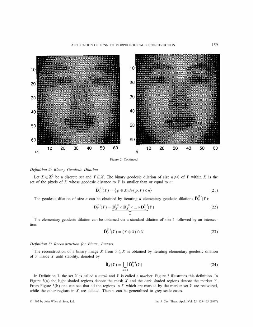
as shown in Figure 2(a). Figure 2(b) shows a grey-scale image X of size 63×63 with 256 grey levels. Figure2(c) shows the output of the dilation FCNN. The input is X . Figure 2(d) shows the output of the erosionFCNN. The input is X . Figure 2(e) shows the output of the dilation FCNN when the image in Figure 2(d)is the input. Thus it is the opening of X . Figure 2(f) shows the output of the erosion FCNN when the imagein Figure 2(c) is the input. Thus it is the closing of X .
4. MORPHOLOGICAL GREY-SCALE RECONSTRUCTIONUSING FUZZY CELLULAR NEURAL NETWORKS
We �rst give the concepts of morphological reconstruction18; 19; 21 brie y. Let an image I be a mapping froma �nite rectangular subset DI of the discrete plane Z2 into a discrete set E = {0; 1; :::; N − 1} of grey levels.A binary image I can only take values 0 or 1 and is often regarded as the set of its pixels with value 1.Given a set X and two pixels p; q ∈ X , the geodesic distance between p and q, dX (p; q), is the length ofthe shortest paths joining p and q which are included in X .
? 1997 by John Wiley & Sons, Ltd. Int. J. Circ. Theor. Appl., Vol. 25, 153–165 (1997)

158 T. YANG AND L.-B. YANG
Figure 2. Implementation of basic morphological operations on grey-scale image using FCNN: (a) The non- at grey-scale structuringelement; (b) a grey-scale image of face of Chinese girl; (c) output of dilation FCNN when input is image in (b); (d) output of erosionFCNN when input is image in (b); (e) output of dilation FCNN when input is image in (d)—it is opening of image in (b); (f) output
of erosion FCNN when input is image in (c)—it is closing of image in (b)
Int. J. Circ. Theor. Appl., Vol. 25, 153–165 (1997) ? 1997 by John Wiley & Sons, Ltd.
APPLICATION OF FCNN TO MORPHOLOGICAL RECONSTRUCTION 159
Figure 2. Continued
De�nition 2: Binary Geodesic Dilation
Let X ⊂Z2 be a discrete set and Y ⊆X . The binary geodesic dilation of size n¿0 of Y within X is theset of the pixels of X whose geodesic distance to Y is smaller than or equal to n:
D(n)X (Y ) = {p ∈ X |dX (p; Y )6n} (21)
The geodesic dilation of size n can be obtained by iterating n elementary geodesic dilations D(1)X (Y ):
D(n)X (Y ) = D
(1)X ◦ D(1)X ◦ ::: ◦ D(1)X︸ ︷︷ ︸
n
(Y ) (22)
The elementary geodesic dilation can be obtained via a standard dilation of size 1 followed by an intersec-tion:
D(1)X (Y ) = (Y ⊕ S) ∩ X (23)
De�nition 3: Reconstruction for Binary Images
The reconstruction of a binary image X from Y ⊆X is obtained by iterating elementary geodesic dilationof Y inside X until stability, denoted by
RX (Y ) =⋃n¿1
D(n)X (Y ) (24)
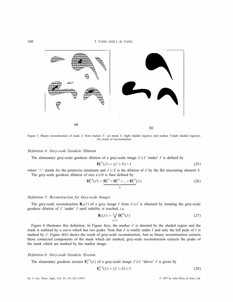
In De�nition 3, the set X is called a mask and Y is called a marker. Figure 3 illustrates this de�nition. InFigure 3(a) the light shaded regions denote the mask X and the dark shaded regions denote the marker Y .From Figure 3(b) one can see that all the regions in X which are marked by the marker set Y are recovered,while the other regions in X are deleted. Then it can be generalized to grey-scale cases.
? 1997 by John Wiley & Sons, Ltd. Int. J. Circ. Theor. Appl., Vol. 25, 153–165 (1997)
160 T. YANG AND L.-B. YANG
Figure 3. Binary reconstruction of mask X from marker Y : (a) mask X (light shaded regions) and marker Y (dark shaded regions);(b) result of reconstruction
De�nition 4: Grey-scale Geodesic Dilation
The elementary grey-scale geodesic dilation of a grey-scale image J6I ‘under’ I is de�ned by
D(1)I (J ) = (J ⊕ S) ∧ I (25)
where ‘∧’ stands for the pointwise minimum and J ⊕ S is the dilation of J by the at structuring element S.The grey-scale geodesic dilation of size n¿0 is then de�ned by
D(n)I (J ) = D(1)I ◦D(1)I ◦ ::: ◦D(1)I︸ ︷︷ ︸
n
(J ) (26)
De�nition 5: Reconstruction for Grey-scale Images
The grey-scale reconstruction RI (J ) of a grey image I from J6I is obtained by iterating the grey-scalegeodesic dilation of J ‘under’ I until stability is reached, i.e.
RI (J ) =∨n¿1
D(n)I (J ) (27)
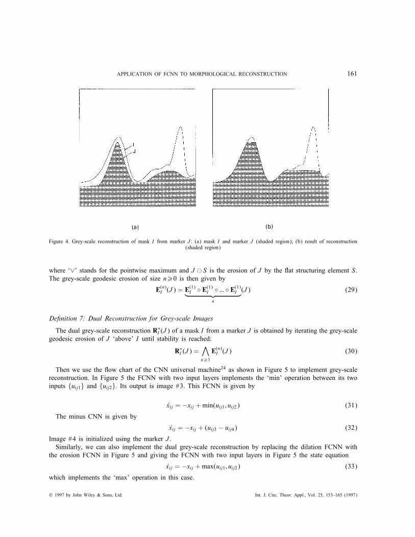
Figure 4 illustrates this de�nition. In Figure 4(a), the marker J is denoted by the shaded region and themask is outlined by a curve which has two peaks. Note that J is totally under I and only the left peak of I ismarked by J . Figure 4(b) shows the result of grey-scale reconstruction. Just as binary reconstruction extractsthose connected components of the mask which are marked, grey-scale reconstruction extracts the peaks ofthe mask which are marked by the marker image.
De�nition 6: Grey-scale Geodesic Erosion
The elementary geodesic erosion E(1)I (J ) of a grey-scale image J¿I ‘above’ I is given by
E(1)I (J ) = (J S) ∨ I (28)
Int. J. Circ. Theor. Appl., Vol. 25, 153–165 (1997) ? 1997 by John Wiley & Sons, Ltd.
APPLICATION OF FCNN TO MORPHOLOGICAL RECONSTRUCTION 161
Figure 4. Grey-scale reconstruction of mask I from marker J : (a) mask I and marker J (shaded region); (b) result of reconstruction(shaded region)
where ‘∨’ stands for the pointwise maximum and J S is the erosion of J by the at structuring element S.The grey-scale geodesic erosion of size n¿0 is then given by
E(n)I (J ) = E(1)I ◦ E(1)I ◦ ::: ◦ E(1)I︸ ︷︷ ︸
n
(J ) (29)
De�nition 7: Dual Reconstruction for Grey-scale Images
The dual grey-scale reconstruction R∗I (J ) of a mask I from a marker J is obtained by iterating the grey-scalegeodesic erosion of J ‘above’ I until stability is reached:
R∗I (J ) =∧n¿1
E(n)I (J ) (30)
Then we use the ow chart of the CNN universal machine24 as shown in Figure 5 to implement grey-scalereconstruction. In Figure 5 the FCNN with two input layers implements the ‘min’ operation between its twoinputs {uij1} and {uij2}. Its output is image #3. This FCNN is given by
xij = −xij +min(uij1; uij2) (31)
The minus CNN is given by
xij = −xij + (uij3 − uij4) (32)
Image #4 is initialized using the marker J .Similarly, we can also implement the dual grey-scale reconstruction by replacing the dilation FCNN with
the erosion FCNN in Figure 5 and giving the FCNN with two input layers in Figure 5 the state equation
xij = −xij +max(uij1; uij2) (33)
which implements the ‘max’ operation in this case.
? 1997 by John Wiley & Sons, Ltd. Int. J. Circ. Theor. Appl., Vol. 25, 153–165 (1997)

162 T. YANG AND L.-B. YANG
Figure 5. Flow chart of CNN universal machine for implementation of grey-scale reconstruction using FCNN
To illustrate the usefulness of the FCNN-based grey-scale reconstruction algorithm, we used this algorithmto remove black dot noises as shown in Figure 6. Figure 6(a) shows the image in Figure 2(b) with someblack dot noises. The noises can be removed by applying the opening operation as shown in Figure 6(b). Thestructuring element is given by
S =
0 0 00 0 00 0 0
(34)
It is a at structuring element with height 0. Comparing the image in Figure 6(b) with the one in Figure 2(b),one can see that some details of the original image are also removed. To overcome this problem, we use theimage in Figure 6(a) as mask I and that in Figure 6(b) as marker J and apply the grey-scale reconstructionalgorithm. The output is shown in Figure 6(c). One can see that some details are recovered.Another application of the FCNN-based grey-scale reconstruction algorithm is scratch removal. Although
the traditional CNN can be used to remove scratches in an image,23 the locations of the scratches must beknown in advance. The FCNN can remove scratches in an image without knowing their locations. Figure7(a) shows a scratched version of the image in Figure 2(b). To remove the scratches, we can use theFCNN-based opening operation. The output is shown in Figure 7(b). Then the FCNN-based grey-scale
Int. J. Circ. Theor. Appl., Vol. 25, 153–165 (1997) ? 1997 by John Wiley & Sons, Ltd.

APPLICATION OF FCNN TO MORPHOLOGICAL RECONSTRUCTION 163
Figure 6. Removal of black dot noises using FCNN-based grey-scale reconstruction algorithm: (a) image with black dot noises; (b)output of FCNN-based opening operation; (c) output of FCNN-based grey-scale reconstruction algorithm
reconstruction algorithm is used to recover some details removed by the opening operation. The mask I isthe image shown in Figure 7(a) and the marker J is that in Figure 7(b). Figure 7(c) shows the �nal result.One can see that some details are recovered. The structuring element is as that in equation (34).
? 1997 by John Wiley & Sons, Ltd. Int. J. Circ. Theor. Appl., Vol. 25, 153–165 (1997)

164 T. YANG AND L.-B. YANG
Figure 7. Removal of scratches using FCNN-based grey-scale reconstruction algorithm: (a) scratched image; (b) output of FCNN-basedopening operation; (c) output of FCNN-based grey-scale reconstruction algorithm
Int. J. Circ. Theor. Appl., Vol. 25, 153–165 (1997) ? 1997 by John Wiley & Sons, Ltd.

APPLICATION OF FCNN TO MORPHOLOGICAL RECONSTRUCTION 165
In a CNN universal machine the computational complexity of an algorithm depends on the number oftemplates that the algorithm uses. The number of templates used by the FCNN-based grey-scale reconstructionalgorithm is 3k, where k is the number of loops till the ‘minus CNN’ outputs 0s. k is very sensitive to thestructure of the mask image; in the worst case k may be very close to half the size of the mask image. k isnot sensitive to the size and shape of the structuring element. In the above two simulations, k = 11.
5. CONCLUSIONS
Since the FCNN is a combination of ‘min’ and ‘max’ operations with the parallel dynamics of the CNN, it isvery convenient to implement morphological operations in its structure. Another reason for using the FCNNin morphology is the local property of morphological operations given a relatively small and simply shapedstructuring element. Also, a large structuring element can be decomposed into a set of smaller structuringelements. The FCNN is found to be a universal parallel array to implement morphological operations forprocessing both binary and grey-scale images. In this paper the FCNN is used to implement morphologicalgrey-scale reconstruction. Then this FCNN-based algorithm is used to recover the details which are removedby opening operations.
REFERENCES
1. L. O. Chua and L. Yang, ‘Cellular neural networks: theory and applications’, IEEE Trans. Circuits and Systems, CAS-35, 1257–1290 (1988).
2. T. Roska and J. Wandewalle (eds), Cellular Neural Networks, Wiley, New York, 1994.3. Special issue on cellular neural networks, IEEE Trans. Circuits and Systems—I, CAS-40 (3)(1993).4. Special issue on cellular neural networks, IEEE Trans. Circuits and Systems—II, CAS-40 (3)(1993).5. Special issue on cellular neural networks, Int. J. Circ. Theor. Appl., 20 (5)(1992).6. Special issue on cellular neural networks, Int. J. Circ. Theor. Appl., 23 (5)(1995).7. Special issue on cellular neural networks, Int. J. Circ. Theor. Appl., 24 (1)(1996).8. Special issue on cellular neural networks, Int. J. Circ. Theor. Appl., 24 (3)(1996).9. T. Roska and L. O. Chua, ‘Cellular neural networks with non-linear and delay-type template elements and non-uniform grids’, Int.
J. Circ. Theor. Appl., 20, 469–481 (1992).10. H. Harrer and J. A. Nossek, ‘Discrete-time cellular neural networks’, Int. J. Circ. Theor. Appl., 20, 453–467 (1992).11. T. Yang and L. B. Yang, ‘Fuzzy cellular neural network and its applications’, IEEE Trans. Circuits and Systems—I, submitted.12. T. Yang and L. B. Yang, ‘Fuzzy cellular neural network: a new paradigm for image processing’, Int. J. Circ. Theor. Appl., 1997,
in press.13. T. Yang and L. B. Yang, ‘Applications of fuzzy cellular neural network to Euclidean distance transformation’, IEEE Trans. Circuits
and Systems—I, 44 (3), 242–246 (1997).14. T. Yang and L. B. Yang, ‘Fuzzy cellular neural networks: theory’, Proc. Int. Workshop on Cellular Neural Networks and Their
Applications (CNNA’96), Seville, June 1996, IEEE, New York, 1996, pp. 181–186.15. T. Yang and L. B. Yang, ‘Fuzzy cellular neural networks: applications’, Proc. Int. Workshop on Cellular Neural Networks and
Their Applications (CNNA’96), Seville, June 1996, IEEE, New York, 1996, pp. 225–230.16. T. Yang and L. B. Yang, ‘The global stability of fuzzy cellular neural network’, IEEE Trans. Circuits and Systems—I, CAS-43,
880–883 (1996).17. M. M. Gupta and D. H. Rao, ‘On the principles of fuzzy neural networks’, Fuzzy Sets Syst., 61, 1–18 (1994).18. J. Serra, Image Analysis and Mathematical Morphology, Academic, New York, 1982.19. J. Serra, Image Analysis and Mathematical Morphology, Part II: Theoretical Advances, Academic, London, 1988.20. M. Grabish and M. Schmitt, ‘Mathematical morphology, order �lters and fuzzy logic’, Proc. IEEE Int. Conf. on Fuzzy Systems,
Yokohama, March 1995, IEEE, New York, 1995, Vol. 4, pp. 2103–2108.21. L. Vincent, ‘Morphological grey-scale reconstruction in image analysis: applications and e�cient algorithms’, IEEE Trans. Image
Process., IP-2, 176–201 (1993).22. R. M. Haralick, S. R. Sternberg and X. Zhuang, ‘Image analysis using mathematical morphology’, IEEE Trans. Pattern Anal.
Mach. Intell., PAMI-9, 532–550 (1987).23. P. L. Venetianer, F. Werblin, T. Roska and L. O. Chua, ‘Analogic CNN algorithm for some image compression and restoration
tasks’, IEEE Trans. Circuits and Systems—I, CAS-42, 278–284 (1995).24. T. Roska and L. O. Chua, ‘The CNN universal machine: an analogic array computer’, IEEE Trans. Circuits and Systems—II,
CAS-40, 163–167 (1993).
? 1997 by John Wiley & Sons, Ltd. Int. J. Circ. Theor. Appl., Vol. 25, 153–165 (1997)