application of hazop, lopa and sil to the alkylation unit...
TRANSCRIPT
Application of HAZOP, LOPA and SIL to the alkylation unit catalyzed with hydrofluoric acid at Ecopetrol Refinery in Cartagena – Colombia
Stefanny Paola Figueroa Jimenez Stefany Carolina Lombana Carmona
Ingry Raquel Ruiz De La Cruz
Report to the internship in the Mary Kay O’Connor Process Safety Center Texas A&M University

1
1. PROJECT IDENTIFICATION
1.1 GENERAL INFORMATION
Report Type: Partial Final Report No. _2_ of 2015
Delivery Date of Report
PROJECT TITLE Application of HAZOP, LOPA and SIL to the alkylation unit catalyzed with hydrofluoric acid at Ecopetrol
Refinery in Cartagena – Colombia
Code
Advisor Dr. Sam Mannan
Researchers Stefanny Paola Figueroa Jimenez, Stefany Carolina Lombana Carmona, Ingry Raquel Ruiz De La Cruz
Financial entity Mary Kay O’Connor Process Safety Center- Texas A&M University
Project Start Date January 12 to Jun 30 of 2015
City/ Country College Station Texas – United States
X
2
OUTLINE
3. INTRODUCTION .................................................................................................................................................................................................... 6
4. OBJECTIVE ........................................................................................................................................................................................................... 7
4.1. General Objective ........................................................................................................................................................................................... 7
4.2. Specific Objectives ......................................................................................................................................................................................... 7
ACHIEVEMENT OF GOALS ............................................................................................................................................................................................ 8
Achievement of general objective ..................................................................................................................................................................................... 8
Achievement of specific objective - ................................................................................................................................................................................... 9
5. BACKGROUND ................................................................................................................................................................................................... 14
6. METHODOLOGY ................................................................................................................................................................................................. 15
7. LITERATURE REVIEW ......................................................................................................................................................................................... 28
7.1. HF ALKYLATION ......................................................................................................................................................................................... 28
7.2. HAZARD AND OPERABILITY “HAZOP” ......................................................................................................................................................... 31
7.3. LAYER OF PROTECTION ANALYSIS “LOPA” ................................................................................................................................................ 33
7.4. SAFETY INTEGRITY LEVEL “SIL” ................................................................................................................................................................. 38
8. DEFINITION OF THE PROBLEM ........................................................................................................................................................................... 40
9. IDENTIFICATION OF IMPORTANT ISSUES .......................................................................................................................................................... 41
10. ANALYSIS OF ISSUES..................................................................................................................................................................................... 42
10.1. HAZOP ........................................................................................................................................................................................................ 42
10.2. LOPA & SIL ................................................................................................................................................................................................. 62
11. CONCLUSIONS ............................................................................................................................................................................................... 84
12. FUTURE WORKS ............................................................................................................................................................................................ 85
3
13. SCHEDULE ..................................................................................................................................................................................................... 86
14. ABBREVIATIONS AND ACRONYMS ................................................................................................................................................................. 88
15. ACKNOWLEDGMENTS .................................................................................................................................................................................... 90
16. REFERENCES................................................................................................................................................................................................. 91
17. LIST OF ANNEXES .......................................................................................................................................................................................... 94

4
LIST OF ANNEX
Annex 1 Application of HAZOP methodology to Selective Hydrogenation Section............................................................................... 94
Annex 2 Application of HAZOP methodology to Charge and Drying section ...................................................................................... 117
Annex 3 Application of HAZOP methodology to Reaction section ..................................................................................................... 128
Annex 4 Application of HAZOP methodology to Acid Storage section ............................................................................................... 134
Annex 5 Application of HAZOP methodology to Cooling Water Tower – TAE- section ...................................................................... 137
Annex 6 Application of HAZOP methodology to Isostripper section ................................................................................................... 139
Annex 7 Application of HAZOP methodology to Depropanizer and HF Stripper section .................................................................... 147
Annex 8 Application of HAZOP methodology to Propane Treatment section ..................................................................................... 159
Annex 9 Application of HAZOP methodology to Debutanization and Alkylate Treatment section ...................................................... 166
Annex 10 Application of HAZOP methodology to N-Butane Treatment section ................................................................................. 173
Annex 11 Application of HAZOP methodology to ALKAD Regeneration section ................................................................................ 184
Annex 12 Application of HAZOP methodology to HF Regeneration section....................................................................................... 192
Annex 13 Application of HAZOP methodology to Effluent Treatment section .................................................................................... 206
Annex 14 Application of LOPA and SIL methodology to Selective Hydrogenation section ................................................................. 213
Annex 15 Application of LOPA and SIL methodology to Charge and Drying section ......................................................................... 214
Annex 16 Application of LOPA and SIL methodology to Reaction section ......................................................................................... 215
Annex 17 Application of LOPA and SIL methodology to Propane Treatment section ......................................................................... 216
Annex 18 Application of LOPA and SIL methodology to Debutanization and Alkylate Treatment section .......................................... 217
Annex 19 Application of LOPA and SIL methodology to N-Butane Treatment section ....................................................................... 218
Annex 20 Application of LOPA and SIL methodology to Cooling Water Tower -TAE- section ............................................................ 219
Annex 21 Application of LOPA and SIL methodology to HF Regeneration section ............................................................................ 220
Annex 22 Application of LOPA and SIL methodology to Effluent Treatment section .......................................................................... 223

5
2. SUMMARY
In a refinery, an alkylation unit is the process of producing gasoline range material (alkylate) from olefins such as propylene, butylenes and amylene, and
isobutene. This unit comes after a fluid catalytic cracking unit (FCCU) with the purpose of convert the high molecular weight hydrocarbons into smaller particles
and more volatile compounds. The alkylation process is used to comply with specific requirements through the conversion of octane in a component of high octane
gasoline. Usually the feed stream to the alkylation unit comes from the FCC, but the components react in the presence of a strong catalyst as hydrofluoric acid or
sulfuric acid. Ecopetrol's refinery in Cartagena Colombia use hydrofluoric acid as catalyst. The HF is a very corrosive and toxic inorganic acid. The HF is used in
the production of aluminum and chlorofluorocarbons, and in the glass etching and chemical industries. Acute (short-term) inhalation exposure to gaseous
hydrogen fluoride can cause severe respiratory damage in humans, including severe irritation and pulmonary edema, severe ocular irritation and dermal burns
may occur following eye or skin exposure in humans [US EPA, 2000]; for these reason it is necessary to treat with extreme care, especially in process which water
is used for cleaning process.
Considering the safety of the plant, hydrofluoric acid raises the most issues due to its properties and the effects to humans, flora, and fauna. One of the most
relevant properties of the hydrofluoric acid is the low vapor pressure, so it is easily vaporized if leak occurs in the units. HF can travel significant distance
downward as a dense vapor. Even though a small concentration of hydrofluoric acid is used in the reaction, it is still enough to cause human and environmental
problems. The objective of this research was to decrease the HF hazards applying HAZOP, LOPA and SIL methodologies. This study is based on the assumption
that the process always operating inside intended design, thus the risks and operability problems are unlikely to occur. The methodology used is to guide words to
identify deviations in the process including the design of the HF alkylation unit.
We evaluated potentially hazardous scenarios and generated recommendations to mitigate these consequences or improve operational capability. Hazardous
scenarios and any associated recommendations were categorized during the research was: safety, environmental and financial; each topic was also risk ranked to
assess the strength of existing safeguards. These causes were identified including human error, equipment failure and external events. Severity of deviations was
evaluated without any protection or safeguards.

6
HF alkylation plant has 13 units which were evaluated and studied and we obtained1092 possible deviations or causes and recommendations in the HAZOP study.
24 of these scenarios are considered significant and high risk and were analyzed in detailed analysis applying LOPA and SIL methodologies. These analysis
providing layers protections to mitigate the hazardous scenarios founded in the HAZOP study, then is necessary identify which of these layer protection are
considered independent protection layer and assign a value of PFD (probability of failure on demand) of each safeguards that was used to get the SIL range.
The detailed issues about the safety study in the unit is provided in this report to show a summary with the recommendations and conclusions obtained through the
study generating a worksheet which has the possible causes, safeguards and risk ranking were evaluated.
3. INTRODUCTION
The petroleum refining industry has always accepted the potential for hazard created by the alkylation units due to uses two systems, either Sulfuric acid or
Hydrofluoric acid, both are considered hazardous substances and has been consistently secured, by the mechanical, metallurgical specifications and operational
practice utilized in the design, construction and the operation of these units which it has achieved a high level of security. [Ecopetrol, 2014]
In this study is evaluated the alkylation process catalyzed with hydrofluoric acid. The alkylation unit performs an important role due to that it produces a high-value
alkylate, which is used as a gasoline blending component. Consequently, refineries operating HF alkylation units are under increasing pressure to maximize the
safety of the unit, product quality, the operational procedures and decreasing of the environmental impact. The efficient operation of alkylation units with HF is a
difficult task and subject to the most testing of operating regimes. This is due to a number of industry-specific constraints and operating issues that stretch the
processing capability of the plant. [Simpson, et al. 2007]
Ecopetrol´s Cartagena Colombia refining has an alkylation plant catalyzed with HF which represents a potential hazards. This kind of process required a detailed
study about the safety and the best operability practices; HAZOP methodology is used to identify major process hazards or operability issues related to the
process design, the most hazardous scenarios include the release of hazardous materials and/or energy like hydrofluoric acid.

7
The aim of this research is analyze the different incidents present in the unit which may impact on health and public safety, worker safety in the workplace,
economic losses, the environment and the company’s reputation. It is required a SIL/ LOPA study since these serves to assess the adequacy of the Safety
Protection Layers (SPLs) or Safeguards that are in place to mitigate events hazardous relating with the process hazards, identify those SPLs or Safeguards that
they are not sufficient to reduce this scenario and to suggest reasonable recommendations which can hazard generates a residual risk that needs further risk
reduction. This is done by defining the tolerable frequency (TF) [Binghman, et al. 2004]. The TF of the process deviation is a number which is derived from the
level of the risk identified from the HAZOP study and we can get it in the risk matrix that Ecopetrol Works. It indicates the period of occurrence, in terms of years, of
the process deviation. The TF values are showing it in the table 2.
4. OBJECTIVE
4.1. General Objective
To develop a study to identify and review best safety practices for proper operation and performance of the alkylation unit catalyzed with hydrofluoric
acid (HF) at the Ecopetrol Refinery in Cartagena-Colombia applying HAZOP, LOPA and SIL methodologies.
4.2. Specific Objectives
Make a literature review to get information about the process operating and general information of the alkylation unit catalyzed with
hydrofluoric acid.
Develop a detailed study concerning the alkylation process, how it works and find the principals variables of the process.
Identify the operating principles of the alkylation unit to select the corresponding nodes which they will be evaluated in detail in each
section of the unit.
8
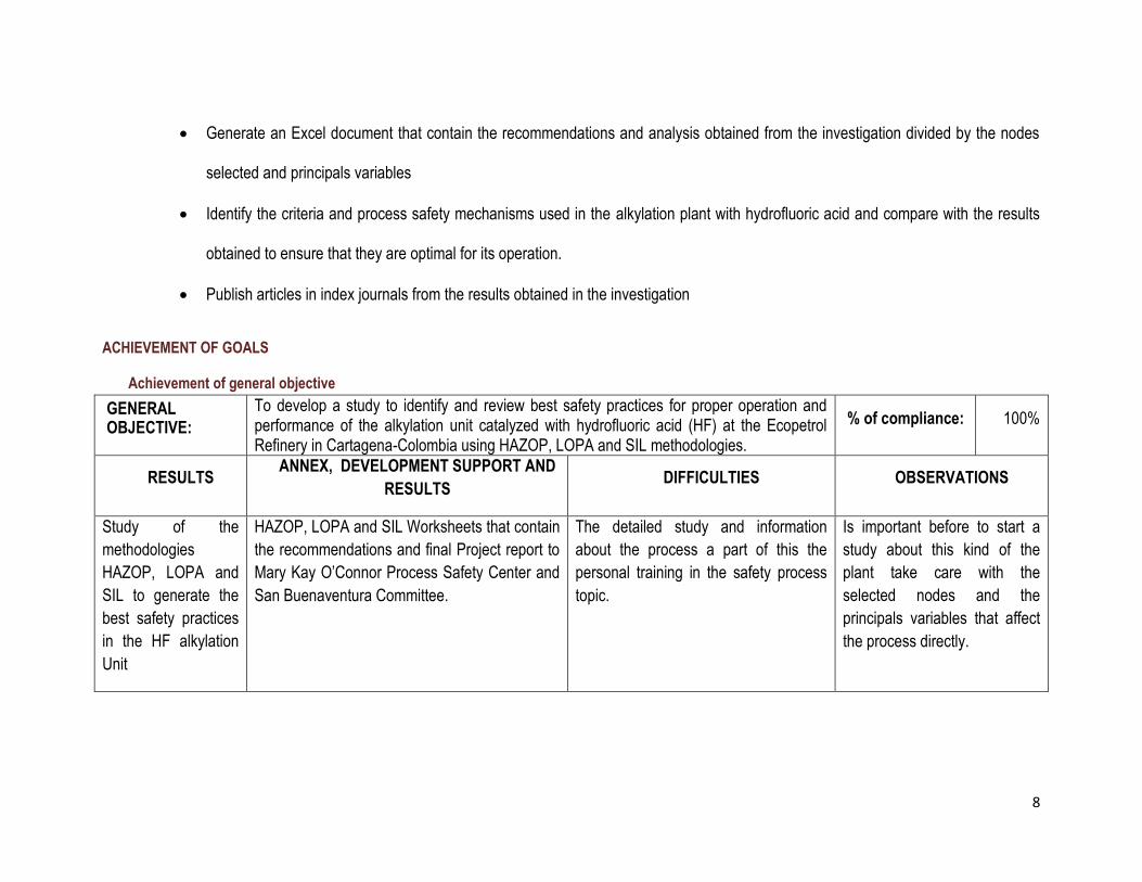
Generate an Excel document that contain the recommendations and analysis obtained from the investigation divided by the nodes
selected and principals variables
Identify the criteria and process safety mechanisms used in the alkylation plant with hydrofluoric acid and compare with the results
obtained to ensure that they are optimal for its operation.
Publish articles in index journals from the results obtained in the investigation
ACHIEVEMENT OF GOALS
Achievement of general objective
GENERAL OBJECTIVE:
To develop a study to identify and review best safety practices for proper operation and performance of the alkylation unit catalyzed with hydrofluoric acid (HF) at the Ecopetrol Refinery in Cartagena-Colombia using HAZOP, LOPA and SIL methodologies.
% of compliance: 100%
RESULTS ANNEX, DEVELOPMENT SUPPORT AND
RESULTS DIFFICULTIES OBSERVATIONS
Study of the
methodologies
HAZOP, LOPA and
SIL to generate the
best safety practices
in the HF alkylation
Unit
HAZOP, LOPA and SIL Worksheets that contain
the recommendations and final Project report to
Mary Kay O’Connor Process Safety Center and
San Buenaventura Committee.
The detailed study and information
about the process a part of this the
personal training in the safety process
topic.
Is important before to start a
study about this kind of the
plant take care with the
selected nodes and the
principals variables that affect
the process directly.

9
Achievement of specific objective -
SPECIFIC OBJECTIVE: 1 Make a literature review to get information about the process operating and general information of the alkylation unit catalyzed with hydrofluoric acid
% of compliance: 100%
RESULT PRODUCT
(if applicable)
ANNEX, DEVELOPMENT
SUPPORT AND RESULTS OBSERVATIONS
Resolve doubt about the
process and personal training in
alkylation units catalyzed with
hydrofluoric acid and process
safety methodologies.
Report submitted to
Universidad de San
Buenaventura Cartagena and
personal training.
Report that contain part of the
literature review used in the project.
When realized this kind of review is
recommendable get information
about similar plants and process
safety methodologies.
10
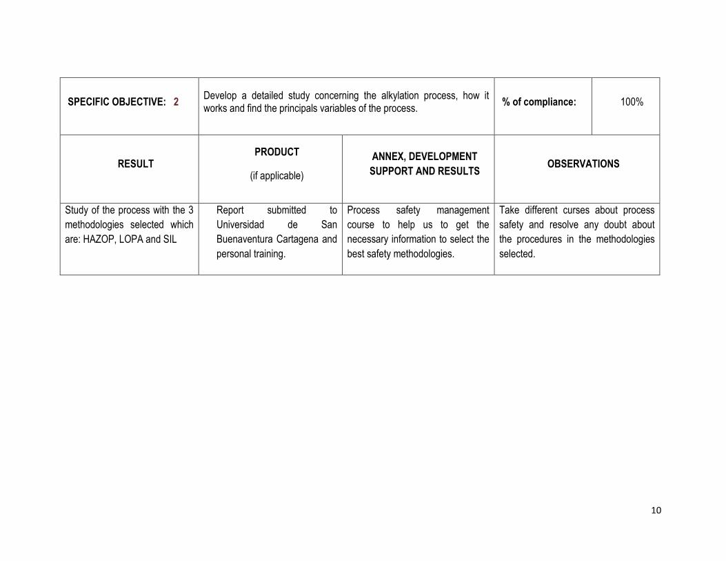
SPECIFIC OBJECTIVE: 2 Develop a detailed study concerning the alkylation process, how it works and find the principals variables of the process.
% of compliance: 100%
RESULT PRODUCT
(if applicable)
ANNEX, DEVELOPMENT
SUPPORT AND RESULTS OBSERVATIONS
Study of the process with the 3
methodologies selected which
are: HAZOP, LOPA and SIL
Report submitted to
Universidad de San
Buenaventura Cartagena and
personal training.
Process safety management
course to help us to get the
necessary information to select the
best safety methodologies.
Take different curses about process
safety and resolve any doubt about
the procedures in the methodologies
selected.
11
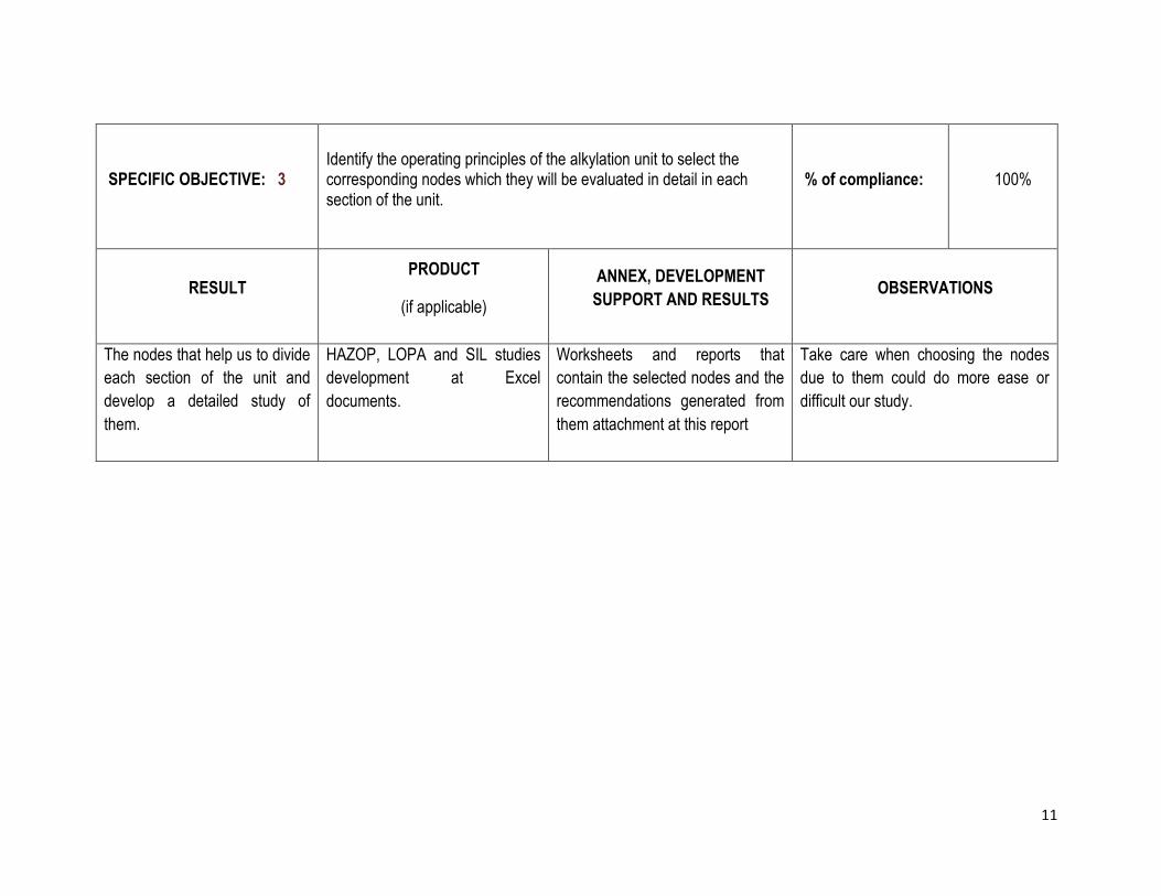
SPECIFIC OBJECTIVE: 3 Identify the operating principles of the alkylation unit to select the corresponding nodes which they will be evaluated in detail in each section of the unit.
% of compliance: 100%
RESULT PRODUCT
(if applicable)
ANNEX, DEVELOPMENT
SUPPORT AND RESULTS OBSERVATIONS
The nodes that help us to divide
each section of the unit and
develop a detailed study of
them.
HAZOP, LOPA and SIL studies
development at Excel
documents.
Worksheets and reports that
contain the selected nodes and the
recommendations generated from
them attachment at this report
Take care when choosing the nodes
due to them could do more ease or
difficult our study.

12
SPECIFIC OBJECTIVE: 4 Generate an Excel document that contain the recommendations and analysis obtained from the investigation divided by the nodes selected and principals variables
% of compliance: 100%
RESULT PRODUCT
(if applicable)
ANNEX, DEVELOPMENT
SUPPORT AND RESULTS OBSERVATIONS
Recommendations from the
detailed study to generate the
conclusions necessary to the
project.
Excel documents when the
person can get the detailed
study and the recommendations
that we got from each possible
scenario of the process.
Excel with worksheets that contain
the selected nodes, principal
variables and possible scenarios
that were used to get the
recommendations about the best
safety practices in the process
attachment at this report.
Did a study about the general
worksheet used in this methodologies
(HAZOP, LOPA and SIL).

13
SPECIFIC OBJECTIVE: 5 Identify the criteria and process safety mechanisms used in the alkylation plant with hydrofluoric acid and compare with the results obtained to ensure that they are optimal for its operation.
% of compliance: 100%
RESULT PRODUCT
(if applicable)
ANNEX, DEVELOPMENT
SUPPORT AND RESULTS OBSERVATIONS
A report that contain the
conclusions and
recommendations generates
during the investigation
This document and other report
delivered to Mary Kay O’Connor
process safety center which are
has some conclusions and
recommendations about the best
safety practices in the HF
alkylation unit embodied at
recommendations generated from
HAZOP, LOPA and SIL analysis
Reports to the Mary Kay O’Connor
Process Safety Center and San
Buenaventura University Committee
to show all information generated
from the project and the results
Did a specific study about the
methodologies used by Ecopetrol
Refinery and the methodologies used
for international refineries.

14
SPECIFIC OBJECTIVE: 6 Publish articles in index journals from the results obtained in the investigation
% of compliance: 50%
RESULT PRODUCT
(if applicable)
ANNEX, DEVELOPMENT
SUPPORT AND RESULTS OBSERVATIONS
Publication of articles from the
results obtained of the
investigations
Developing In this moment we are developing the
article to send it to some scientific
journals
5. BACKGROUND
The HAZOP, LOPA and SIL studies are excellent tools to analyze and provide recommendations and good practices for prevent accidents and risks in a work
place or plant. The scope of this study included all process equipment, piping, and instrumentation for the systems defined using the Process Flow Diagrams
(PFDs), Piping & Instrument Diagrams (P&lDs) and operating under normal steady state conditions or in response to a process variation.
The hazard scenarios were categorized during the research as being:
• Safety (S): including catastrophic events such as explosions or fires, other personnel injury events, and off-site consequences.
• Environmental (E): including any legal or company violation.

15
• Financial (F): including equipment damage or operability issues.
Each scenario was also risk ranked to assess the strength of existing safeguards. When employed properly, a risk ranking system helps to identify gaps in
process safety.
6. METHODOLOGY
The methodology used to elaborate HAZOP, LOPA and SIL study are described below:
The P&IDs were divided into manageable sections called nodes. These systems were systematically analyzed. The HF alkylation unit study contains forty eight
(48) nodes. The details of these nodes are show in the Worksheet in a excel document which are attached with this documents.
HAZOP analysis is a process hazard analysis method which has been widely used in chemical process industries, especially in some complex process plants.
Processes, human operations, many pieces of equipment, a mass of material, a number of instruments, several control systems, safety and environment, etc.,
interweave to form a complex process plant. Human operations always play a tremendous role in running the plant. In an analysis process, P&ID of the complex
process plant should be examined by a multi-disciplinary team of experts systematically, and all conceivable deviations far from design intentions in the plant can
be identified and all the possible abnormal causes and the adverse consequences of these deviations can be determined.
The considerations of the experts are provided in the following two aspects: 1) determining whether a given operation or activity has the potential to give rise to a
hazardous situation, 2) determining the range of hazardous events that the operation or activity could present.
In the process we found some of the possible causes that can divert the conditions of the process, which are::
16
Failure in the equipment, instrumentation, or in the piping. Equipment failures were not considered at a specific level. For example, the form that the
equipment fails including the instruments control that this has.
Human error such as performing a wrong operation, failing to perform a required operation, misdiagnosing an operating problem, performing an operation
at the wrong time, mal-operation of equipment, and administrative failure in which a faulty system causes a hazard
External events such as loss of utilities to the process unit (electrical power, steam, cooling water, instrument air), climatic conditions (e.g. solar heating),
or external fire
Long-term processes which, if ignored, could cause potential hazardous deviations. Examples fouling in exchangers, corrosion/erosion possibilities. If this
not is ensured could represent a hazardous for the unit
Previous incidents
When we based if occur a deviation from equipment and process design was necessary follow these steps to identify possible consequences and generate
recommendations to mitigate the deviations.
1. First consider that the consequences don't have any safeguards, that is for studying the worst case scenario and generate the correctly
recommendations that can avoid that this consequence occur
2. Take the most severity consequence. In some cases, that might be considering the most consequence and lower likelihood, while in other cases it might
be most likely but less consequential outcome.
3. Consequences shall be identified according to Safety, Environmental, and Financial.
We document the safeguards for prevention and/or mitigation of the consequences. The unit has a system which is defined between the P&IDs, PFD and general
information about it, that for know how to prevent or mitigate the hazard from the recommendations that was found:
1. Safeguards (engineering and administrative controls)
2. Typical safeguards that prevent or minimize consequences and likelihoods which include:

17
• Process design
• Control (basic process control systems, process alarms, operating procedures, Operator intervention)
• Prevention (safety critical process alarms, safety instrumented systems)
Each cause-consequence combination which constitutes a hazard scenario was ranked, wherever possible, by us according to its estimated severity and likelihood
of occurrence. Most causes have multiple consequences where each consequence has a likelihood of occurrence.
Specifically ranking the likelihood of different consequences recognizes that a hazardous scenario may be interrupted or mitigated by shutdown instrumentation,
operator intervention, or emergency response before the hazard can fully develop.
Thus, while the severity level of consequences can increase dramatically as each consequence is considered, the likelihood of occurrence may decrease
significantly.
The company uses 5 levels severities which were assigned to each consequence, assuming that any safeguards within the process unit did not respond as
designed. However, the likelihoods were assigned assuming that safeguards function fully and work as designed. The definitions for the severity levels used in the
study are given in Table 1, and the definitions for the likelihood levels are given in Table 2.

18
Table 1. Severity code desviations
Table 2. Likelihood Definitions

19
The severity and likelihood are considered jointly using a Risk Ranking Matrix to determine appropriate prioritization of the scenarios and associated
recommendations as shown in Table 3 below.
Table 3. Risk Matrix

20
The risk ranking has a meaning depending of the color which will show in the table 4.
Table 4. Risk Ranking Definitions
Layers of protection analysis (LOPA) is a powerful analytical tool for assessing the adequacy of protection layers used to mitigate process risk. LOPA builds upon
well-known process hazards analysis techniques, applying semi-quantitative measures to the evaluation of the frequency of potential incidents and the probability
of failure of the protection layers.
However, risks of incidents caused by reactive chemicals have not been well addressed due partly to sparse failure frequency data. In this paper, the semi-
quantitative layer of protection analysis (LOPA) approach is used to estimate reactive chemical risk, and the probabilities or frequencies of failure scenarios are
addressed. Using LOPA, reactive risks can be evaluated with respect to predefined criteria, and the effectiveness of risk reduction measures can be assessed
In other words, the concept of layers of protection is illustrated in Figure 1. The combined effects of the protection layers and the consequences are compared
against some risk tolerance criteria that for Ecopetrol S.A. is 1x10^-8/years.

21
Figure 1. Layers of protection to lower the frequency of a specific accident
Physical protection (Relief Devices)
Plant Emergency Response
Community Emergency Response
Process Design
Community Emergency Response
Physical protection (Relief Devices)
Plant Emergency Response
Post-Response Physical Protection
Safety Instrumented Functions
Critical Alarms and Human
Basic Process Control Sytems

22
The major steps for LOPA study include:
Extract the possible causes from HAZOP study which are categorized in High and Significant risk.
Estimate the potential risk (severity, frequency, exposition factor …) of event no mitigated.
Define tolerable risk (tolerable maximum frequency of mitigated event).
Analyze the layers protections and establish the independent protection layers and assign a risk factor reduction.
Estimate the overall consequence frequency multiplying the value of PFD of each safeguards and frequency to comparison with acceptable risk
criteria that in this case the value is 1x10^-8/years.
Evaluate and repeat the process if is necessary. If the value of the overall consequence is higher than the acceptable risk criteria is necessary reduce
it suggesting others independent protection layer (IPL) and calculate a new overall consequence until the value is lower or equal to the acceptable
risk criteria.
All these steps are repeated for the scenarios categorized in high and significant risk.
Layers protection
The safeguards identified during the HAZOP study, then establish which of these safeguards are consider independent protection layers (IPLs):
Process control system
Alarms and operator actions
Active barriers:
- Security events
- Sprinklers, dikes, water curtains….
It’s possible that all of these layers not be independent protection layers.
23
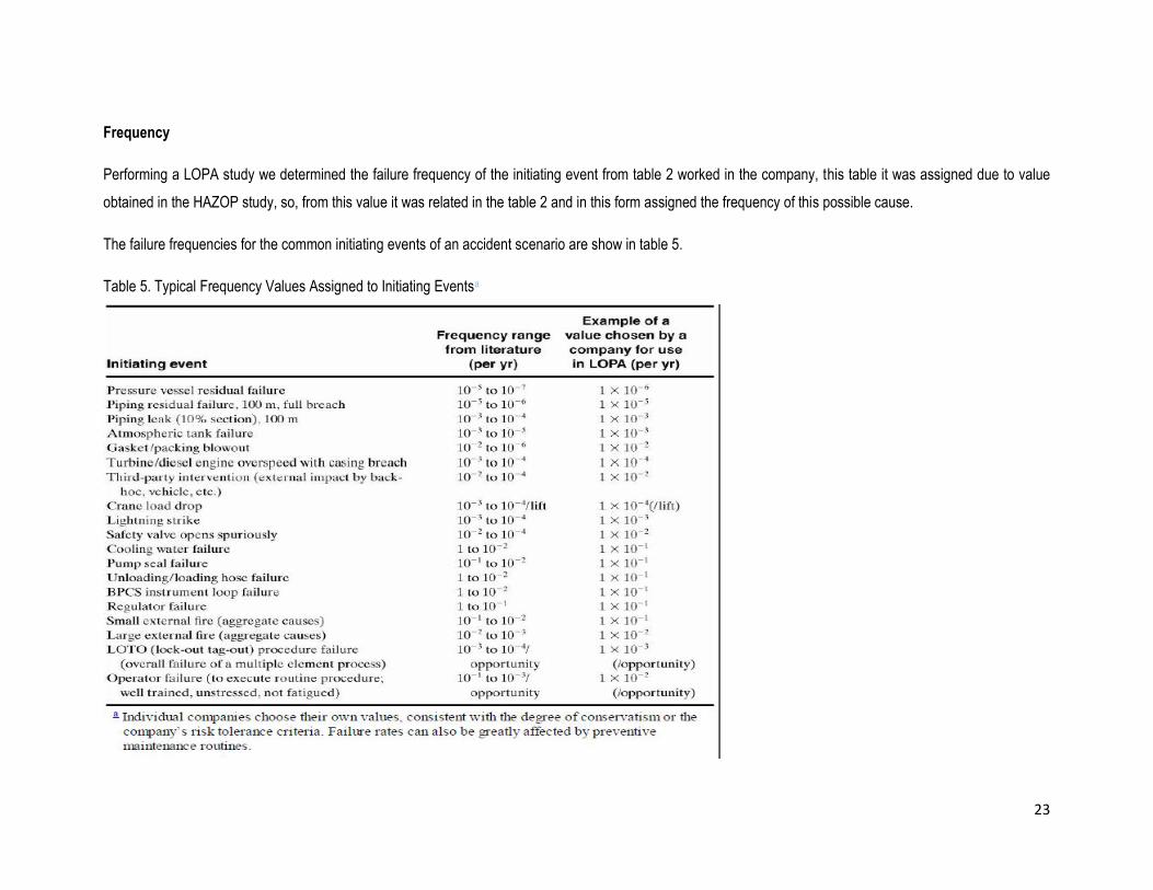
Frequency
Performing a LOPA study we determined the failure frequency of the initiating event from table 2 worked in the company, this table it was assigned due to value
obtained in the HAZOP study, so, from this value it was related in the table 2 and in this form assigned the frequency of this possible cause.
The failure frequencies for the common initiating events of an accident scenario are show in table 5.
Table 5. Typical Frequency Values Assigned to Initiating Eventsa

24
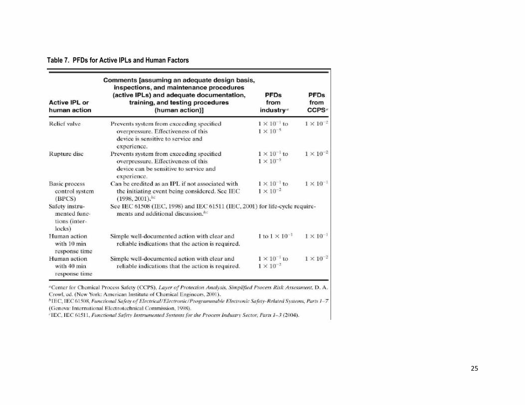
A part of these PFDs it was necessary included PFDs for passive IPLs that are show in table 6 and PFDs for active IPLs and Human Actions that are show in table
7.
Table 6. PFDs for Passive IPLs
25
Table 7. PFDs for Active IPLs and Human Factors

26
From these values it was possible obtain the PFDs of each safeguards and with the frequency we could calculate the overall consequence frequency and compare
with the acceptable risk criteria to know if the deviation needed other IPL to mitigate the hazardous.
The deviations that not exceeded the value assigned for the refinery it was necessary to generate more recommendations or suggest some safeguards to mitigate
the risk.
The last method that we used is Safety integrity level (SIL), which is verification plays a critical role in reliability assessment of safety related systems. In the
industry they ask, to what extent can a process be expected to perform safely? And, in the event of a failure, to what extent can the process be expected to fail
safely? These questions are answered through the assignment of a target Safety Integrity Level (SIL). SILs are measures of the safety risk of a given process.
Safety Integrity Level is a way to indicate the tolerable failure rate of a particular safety function. Standards require the assignment of a target SIL for any new or
retrofitted SIF within the SIS. The assignment of the target SIL is a decision requiring the extension of the Hazards Analysis. The SIL assignment is based on the
amount of risk reduction that is necessary to maintain the risk at an acceptable level. All of the SIS design, operation and maintenance choices must then be
verified against the target SIL. This ensures that the SIS can mitigate the assigned process risk.
Historically, safety thinking categorized a process as being either safe or unsafe. For the new standards, however, safety isn’t considered a binary attribute; rather,
it is stratified into four discrete levels of safety. Each level represents an order of magnitude of risk reduction. The higher the SIL level, the greater the impact of a
failure and the lower the failure rate that is acceptable. In the table 8 shown these level which are accepted in the chemical process industry.

27
Table 8. SIL values
SIL Availability PFDavg Risk Reduction Qualitative Consequences
4 >99.99% 10-5 to <10-4 100,000 to 10,000 Potential for fatalities in the
community
3 99.9% 10-4 to <10-3 10,000 to 1,000 Potential for multiple on-site
fatalities
2 99 to 99.9% 10-3 to <10-2 1,000 to 100 Potential for major on-site injuries
1 90 to 99% 10-2 to <10-1 100 to 10 Potential for minor on-site injuries
This value is obtained from equation 1 when the deviation no exceeded the acceptable risk criteria; if this exceeded this value that is mean the process has the
enough safeguards to mitigate the deviation.
In this case the maximum value for SIL that we obtained was SIL 1 and SIL2
28
7. LITERATURE REVIEW
7.1. HF ALKYLATION
ALKYLATION CURRENT EVENTS, Pam Pryor, 2001
<http://www2.dupont.com/Clean_Technologies/es_MX/assets/downloads/AlkyCurrentEvents2001.pdf>
Alkylation’s importance to refiners continues to grow as alkylate has been termed “liquid gold” for reformulated gasoline. Although well established in the United
States, growth in alkylation capacity has continued through the last decade as U.S. refiners have revamped and expanded existing units, replaced obsolete units,
and in a few cases, added new grassroots units.
Alkylation capacity outside the United States continues to grow as well. Increasing conversion capacity plus increasing demand for gasoline in many areas of the
world has led to the installation of new grassroots alkylation units. Coupled with the need for more gasoline is the need for cleaner gasoline. We see alkylate filling
those needs.
ISOBUTANE ALKYLATION: RECENT DEVELOPMENTS AND FUTURE PERSPECTIVES, Sven Ivar Hommeltoft, 2001
<http://www.sciencedirect.com/science/article/pii/S0926860X01008171>
Alkylation serves to dispose of the C3–C4 cut from the FCC unit by converting much of this cut into alkylate, which is a valuable blending component for the
gasoline pool. The alkylate contains no olefins or aromatics but consists exclusively of isoalkanes. It has a low vapor pressure and a high octane number.There is
little doubt that as long as cars are operatedon high-octane gasoline, isobutane alkylate willcontinue to be a desirable blending component. The trend in motor
gasoline formulation as forced by the legislative requirements has been and will probably continue to be to lower the content of olefins and aromatics and
impurities such as sulfur and nitrogen compounds in order to make the fuel more environmentally friendly.

29
HYDROFLUORIC ACID ALKYLATION, ABB and ConocoPhillips develop a critical new process analysis tool, Michael B. Simpson, Michael
Kester, 2007
<http://www09.abb.com/global/scot/scot271.nsf/veritydisplay/1b9c3c80511554ef8325734b004198cf/$file/22-26%203M774_ENG72dpi.pdf>
The HF alkylation unit (HFU) remains of key importance to this day. It plays a critical role in providing one of the most important feeds to the final pro duct gasoline
blending pool. Its significancehas grown side by side withthe increasing number of fluid catalyticcracking (FCC) units in refineries.The FCC adds value to the heavy
endof crude distillation by catalytically cracking heavy feeds into lighter products such as light cycle oil and FCC gasoline, which can be used either directly or after
hydrotreating in final product blending operations. The downside of this process is that light olefins, typically butene and propene, are also produced in FCC
operations. These are essentially worthless as feedstock. Similarly, in any crude distillation process an excess of light end products such as butane tend to be
produced that are of limited use. N-butane can easily be converted to iso-butane, and in this form it joins the FCC c3 or c4 olefins (butene or propene) as the
combined feeds to the HF alkylation unit.
ABB–ConocoPhillips solution for HFU reactor optimization offers ABB multivariable control technology underpinned by a unique capability for rapid online
characterization of HF acid, recycle iC4, olefin/iC4 makeup feeds and alkylate. Thesolution delivers the following significantoperating improvements to HFalkylation
reactors:
Feed rates, alkylate yield, and alkylate octane are maximized to an economic optimum, subject to operating constraints
Isobutane:olefin (I:O) ratio and energy consumption can be reduced while meeting alkylate quality and yield targets with minimum acid consumption.
Isobutane makeup rate can be optimized while respecting iC4 inventory constraints
30
FUNDAMENTALS OF PETROLEUM REFINING, Chapter 10 – Alkylation, Mohamed A. Fahim, Taher A. Alsahhaf, AmalElkilani, 2010
<http://www.sciencedirect.com/science/article/pii/B9780444527851000103>
This chapter describes alkylation, a process of producing gasoline range material (alkylates) from olefins such as propylene, butylenes and amylene, and
isobutane. Butylene is the most widely used olefin because of the high quality of the alkylate produced. The current trend toward elimination of methyl tertiary butyl
ether has resulted in increased attention to alkylation technology. In alkylation, refinery gases produced from different units are collected and sent to the gas plant.
Olefins and isobutanes are separated and used as a feed to the alkylation plant. Olefins are sent to the polymerization unit. Both alkylation and polymerization
units produce gasoline, which can be sent to the gasoline pool.
The alkylation process consists of running the hydrocarbons in liquid form (enough pressure is used to ensure that) and at low temperature and with a high
isobutane (iC4) to olefin ratio. The reaction products are sent to an acid settler where the acid is recycled back to the reactor. Products are then separated into
gaseous LPG propane and n-butane and the desired product of alkylate.
A RISK TOO GREAT: HYDROFLUORIC ACID IN U.S. REFINERIES, Gary Beevers, Teddy Bender, Kristin Bradley-Bul, et al. 2013
<http://www.usw.org/workplaces/oil/A-Risk-Too-Great.pdf>
Fifty U.S. oil refineries use large volumes of highly concentrated hydrofluoric acid (HF) as chemical catalysts in a process called alkylation. Alkylation creates
additives that boost the octane of gasoline. On average, these 50 refineries each store 212,000 pounds of HF. If released in the atmosphere, HF rapidly forms
dense vapor clouds that hover near land and can travel great distances. Like other powerful acids, HF can cause deep severe burns and damage the eyes, skin,
nose, throat and respiratory system. But the fluoride ion is also poisonous. Entering the body through a burn or by the lungs, it can cause internal damage
throughout the body. At high enough exposures, HF can kill. The Occupational Safety and Health Administration (OSHA) and the Environmental Protection Agency
(EPA) regulate HF as highly toxic.

31
7.2. HAZARD AND OPERABILITY “HAZOP”
HAZARD AND OPERABILITY (HAZOP) ANALYSIS. A LITERATURE REVIEW, JordiDunjó, VasilisFthenakis, Juan A. Vílchez, JosepArnaldos,
2009
<http://www.sciencedirect.com/science/article/pii/S0304389409013727 >
Hazard and operability (HAZOP) methodology is a Process Hazard Analysis (PHA) technique used worldwide for studying not only the hazards of a system, but
also its operability problems, by exploring the effects of any deviations from design conditions.
Our paper is the first HAZOP review intended to gather HAZOP-related literature from books, guidelines, standards, major journals, and conference proceedings,
with the purpose of classifying the research conducted over the years and define the HAZOP state-of-the-art.
A NEW INTELLIGENT ASSISTANT SYSTEM FOR HAZOP ANALYSIS OF COMPLEX PROCESS PLANT, Feng Wang, , JinjiGao, Huaqing Wang,
2012
<http://www.sciencedirect.com/science/article/pii/S0950423012000228>
HAZOP analysis is a process hazard analysis method which has been widely used in chemical process industries, especially in some complex process plants.
Processes, human operations, many pieces of equipment, a mass of material, a number of instruments, several control systems, safety and environment, etc.,
interweave to form a complex process plant. Human operations always play a tremendous role in running the plant. In an analysis process, P&ID of the complex
process plant should be examined by a multi-disciplinary team of experts systematically, and all conceivable deviations far from design intentions in the plant can
be identified and all the possible abnormal causes and the adverse consequences of these deviations can be determined.

32
The considerations of the experts are provided in the following four aspects: 1) determining whether a given operation or activity has the potential to give rise to a
hazardous situation, 2) determining the range of hazardous events that the operation or activity could present.
HAZOP STUDY TRAINING FROM THE 1970S TO TODAY, Brian J. Tyler, 2012
<http://www.sciencedirect.com/science/article/pii/S0957582012000869>
The role of Trevor Kletz in the development of several safety methods is well known and widely acknowledged. These methods include HAZOP study, HAZAN and
inherent safety. Indeed, HAZOP study has been adopted worldwide1 to the point where it is probably the most widely used hazard study method in the process
industry. Less well known is the influence of Kletz on the training methods used for HAZOP study. This paper records his early contributions and continued
influence as well as describing some important developments during the last 40 years. It is based on my experience of organising, since 1978, over 50 public
courses on HAZOP study for the IChemE, over 100 in-company courses for 50 different companies and, most recently, creating an e-learning course in HAZOP
study which has been made available through the IChemE.
PROCESS SAFETY DATA MANAGEMENT PROGRAM BASED ON HAZOP ANALYSIS AND ITS APPLICATION TO AN ETHYLENE
OXIDE/ETHYLENE GLYCOL PLANT, FengWanga, Yankun Zhao, Ou Yang, JingboCai, Mei Deng, 2013
<http://www.sciencedirect.com/science/article/pii/S0950423013001757>
HAZOP analysis is a process hazard analysis method that has been widely applied both within and outside the chemical processing industries. This paper
presents a design method for a process safety data management program for petrochemical plants based on HAZOP analysis and demonstrates the steps of
application involved in building a process safety data management system for an ethylene oxide/ethylene glycol production plant. Firstly, the production data files
and relevant documents of the plants should be classified and stored in the program database as reference documents and treatment schemes for coping with
abnormal situations should be collected and summarized as guidance documents. Secondly, the HAZOP analysis method is employed to identify all the dangerous
deviations possibly existing in the production process of the ethylene oxide/ethylene glycol plant. Then, the relationships among the deviations, the reference
documents and the guidance documents should be considered and evaluated.

33
Finally, each dangerous deviation will be given a corresponding reference document and guidance document. The reference documents and guidance documents
stored in the expert system can be utilized to help operators solve the corresponding technical problems and cope with abnormal situations. The process safety
data management program will contribute to the identification, analysis and resolution of operation problems. When an abnormal situation occurs, according to the
deviations exhibited in the system, the necessary reference documents and guidance documents will be quickly consulted by the operators, and an appropriate
decision will be made to address the abnormal situation. Therefore, by using the process safety data management program, plant security and human safety in the
petrochemical industries will be improved.
7.3. LAYER OF PROTECTION ANALYSIS “LOPA”
SCENARIO IDENTIFICATION AND EVALUATION FOR LAYERS OF PROTECTION ANALYSIS, Kenneth First, 2000
<http://www.sciencedirect.com/science/article/pii/S095042301000094X>
The identification and screening of scenarios has been identified as a source of variation in Layers of Protection Analysis (LOPA). Often the experience of the
analyst is a significant factor in determining what scenarios are evaluated and the worst credible consequences. This paper presents a simplified chemical process
risk analysis that is effective in providing a semi-quantitative measure of consequence that may include human harm and is independent of the analyst. This
process may be used in evaluation of Management of Change, inherently safer design decisions for capital projects and LOPA re-validation.
Conditional and relational logic may be captured with the use of simple spreadsheets to further improve overall efficiency. For example, this method minimizes the
overall time required for scenario development and re-validation relative to Hazard and Operability studies (HAZOP). The technique simplifies established models
used by engineers engaged in the operation or design of a chemical manufacturing facility without special software or training. The results of this technique are
realistic and may be directly compared with corporate or regulatory guidelines for risk of fatality or injury. At each step in the risk analysis process, more detailed or
sophisticated methods may be used to refine the technique. Furthermore, results from any step may indicate that the hazard from a specific scenario case is not
sufficient to continue with subsequent analysis steps.

34
INTRODUCTION TO LAYERS OF PROTECTION ANALYSIS, Angela E. Summers, 2003
<http://www.sciencedirect.com/science/article/pii/S0304389403002425>
Layers of protection analysis (LOPA) is a powerful analytical tool for assessing the adequacy of protection layers used to mitigate process risk. LOPA builds upon
well-known process hazards analysis techniques, applying semi-quantitative measures to the evaluation of the frequency ofpotential incidents and the probability
of failure of the protection layers. This paper will provide anoverview of the LOPA process, highlighting the key considerations.
LAYER OF PROTECTION ANALYSIS FOR REACTIVE CHEMICAL RISK ASSESSMENT, Chunyang Wei, William J. Rogers and M. Sam Mannan,
2008
<http://www.sciencedirect.com/science/article/pii/S0304389408009898>
Reactive chemical hazards have been a significant concern for the chemical process industries (CPI). Without sufficient control and mitigation of chemical reaction
hazards, reactive incidents have led to severe consequences, such as release of flammable and toxic materials, fires and explosions, and threats to human lives,
properties, and the environment. Consequence of reactive hazards can bewell understood through calorimetric testing and computational techniques.
However, risks of incidents caused by reactive chemicals have not been well addressed due partly to sparse failure frequency data. In this paper, the semi-
quantitative layer of protection analysis (LOPA) approach is used to estimate reactive chemical risk, and the probabilities or frequencies of failure scenarios are
addressed. Using LOPA, reactive risks can be evaluated with respect to predefined criteria, and the effectiveness of risk reduction measures can be assessed.
The hydroxylamine (HA) production system is employed as a case study to demonstrate the application of LOPA to reactive chemical risk assessment
35
RISK ASSESSMENT OF LNG IMPORTATION TERMINALS USING THE: BAYESIAN–LOPA METHODOLOGY, GeunWoong Yun, William J. Rogers
and M. Sam Mannan, 2009
<http://www.sciencedirect.com/science/article/pii/S0950423008001344>
In order to meet the fast growing LNG (Liquefied Natural Gas) demand, many LNG importation terminals are now in operation. Therefore, it is important to estimate
potential risks of LNG terminals using LOPA (Layer of Protection Analysis), which can provide quantified results with less time and effort than other methods. For
LOPA applications, failure data are essential to compute risk frequencies. However, available failure data from the LNG industry are sparse and often statistically
unreliable. Therefore, Bayesian estimation, which can update generic failure data with plant-specific failure data, was used to compensate for insufficient LNG
system failure data. This paper shows the need for the Bayesian–LOPA methodology, how to develop the method, and a case study to demonstrate application of
the method. Finally, this paper proposes that the Bayesian–LOPA method is a powerful tool for risk assessment of not only the LNG industry but also in other
industries, such as petrochemical, nuclear, and aerospace.
ExSys-LOPA FOR THE CHEMICAL PROCESS INDUSTRY, Adam S. Markowski and M. Sam Mannan, 2010
<http://www.sciencedirect.com/science/article/pii/S0950423010000525>
The chemical process industries are characterized by the use, processing, and storage of large amounts of dangerous chemical substances and/or energy. Among
different missions of chemical plants there are two very important ones, which: 1. provide a safe work environment, 2. fully protect the environment. These
important missions can be achieved only by design of adequate safeguards for identified process hazards.
Layer of Protection Analysis (LOPA) can successfully answer this question. This technique is a simplified process of quantitative risk assessment, using the order
of magnitude categories for initiating cause frequency, consequence severity, and the likelihood of failure of independent protection layers to analyze and assess
the risk of particular accident scenarios. LOPA requires application of qualitative hazard evaluation methods to identify accident scenarios, including initiating
causes and appropriate safeguards. This can be well fulfilled, e.g., by HAZOP Studies or What-If Analysis.

36
However, those techniques require extensive experience, efforts by teams of experts as well as significant time commitments, especially for complex chemical
process units. In order to simplify that process, this paper presents another strategy that is a combination of an expert system for accident scenario identification
with subsequent application of LOPA. The concept is called ExSys-LOPA, which employs, prepared in advance, values from engineering databases for
identification of loss events specific to the selected target process and subsequently an accident scenario barrier model developed as an input for LOPA.
Such consistent rulesfor the identification of accident scenarios to be analyzed can facilitate and expedite the analysis andthereby incorporate many more
scenarios and analyze those for adequacy of the safeguards. An associated computer program is under development. The proposed technique supports and
extends the Layer of Protection Analysis application, especially for safety assurance assessment of risk-based determination for the process industries. A case
study concerning HF alkylation plant illustrates the proposed method.
A FORMULATION TO OPTIMIZE THE RISK REDUCTION PROCESS BASED ON LOPA, ClementinaRamírez-Marengo, Julio de Lira-Flores,
AntiocoLópez-Molina, RichartVázquez-Román, Victor Carreto-Vázquez and M. Sam Mannan, 2013
<http://www.sciencedirect.com/science/article/pii/S0950423012001052>
LOPA is a semi-quantitative methodology used in risk analysis. LOPA assesses the scenarios such as loss of containment, which can lead into major accidents,
and it also proposes a series of hierarchically organized protective layers. Protective layers are placed to lower the frequency of undesired consequences. The
methodology typically uses order of magnitude to express the initial event frequency, the probability of failure on demand of the independent protection layers and
the magnitude of the consequence.
LOPA methodology typically builds on the information developed during a qualitative hazard evaluation. Then, layers of protection are intended to independently
comply with three main functions: Prevention, protection and mitigation. To be considered as independent protection layers (IPL’s), safeguards need to satisfy
some characteristics: independence, specificity, dependability and auditability (Summers, 2003).
37
LAYER OF PROTECTION ANALYSIS E QUANTIFYING HUMAN PERFORMANCE IN INITIATING EVENTS AND INDEPENDENT PROTECTION
LAYERS, Philip M. Myers, 2013
<http://www.sciencedirect.com/science/article/pii/S095042301200099X>
Layer of Protection Analysis (LOPA) is a highly valued, semiquantitative risk methodology embraced by the process industries and in widespread use. LOPA uses
a relatively simple, scenariobased approach that can effectively address many risk related issues, providing a timely and cost-effective tool to conduct engineering
analyses as an aid to decision making. LOPA is typically used to determine if existing layers of protection are sufficient, and to develop risk reduction measures for
specific scenarios of concern.
A LOPA scenario consists of a single, unique initiating event consequence pair. Generally used for high consequence or high risk scenarios, LOPA generates
additional support and a greater degree of confidence in decisions made as compared to those relying on the use of purely qualitative tools such as Process
Hazard Analysis (PHA). Over the years since the introduction of LOPA to the process industries (CCPS,1993; Dowell,1997), and with the requirements of industry
standards for functional safety (ISA, 2004), it has been used extensively, with a wealth of application experience gained.
There are now many variations of LOPA in practice e some are highly simplified, order-of-magnitude approaches with simple calculations, while others are more
detailed and complex with extensions to quantitative techniques such as Human Reliability Analysis (HRA), Event Tree Analysis (ETA), Fault Tree Analysis (FTA),
and Quantitative Risk Analysis (QRA). LOPA has been stretched in many respects, with new developments in and applications for the methodology, and also
limitations and problems encountered in practical use of LOPA (HSE, 2009a, 2009b; Myers, 2010).

38
7.4. SAFETY INTEGRITY LEVEL “SIL”
DERIVATION OF AN EQUATION FOR QUANTITATIVE SIL ASSIGNMENT, Edward M. Marszal, 2003
<http://www.sciencedirect.com/science/article/pii/S0019057807601220>
As engineers become more experienced with the application of safety instrumented systems (SIS’s), quantitative risk analysis for selection of safety integrity levels
(SIL’s) is becoming more and more common. SIS practitioners have found that qualitative methods for selecting SIL’s are unsatisfactory because they are overly
conservative. The inflated requirements yielded by these qualitative methods are unnecessarily increasing both the capital expense and the ongoing maintenance
cost of SIS’s.
To address the high equipment costs and poor results associated with qualitative selection methods, many sophisticated users of SIS’s are turning to quantitative
methods such as layer of protection analysis and full quantitative risk analysis. Procedures for applying quantitative methods to the SIL selection problem are in the
early stages of development. Literature explaining the use of fully quantitative methods for SIL selection is virtually nonexistent. For these two reasons, many
engineers are forced to use ad hoc methods for the selection process, arriving at equations through questionable methods, some of which are mathematically
incorrect.
A SIL QUANTIFICATION APPROACH BASED ON AN OPERATING SITUATION MODEL FOR SAFETY EVALUATION IN COMPLEX GUIDED
TRANSPORTATION SYSTEMS, J. Beugin, D. Renaux and L. Cauffriez, 2007
<http://www.sciencedirect.com/science/article/pii/S0951832006002201>
Safety analysis in guided transportation systems is essential to avoid rare but potentially catastrophic accidents. This article presents a quantitative probabilistic
model that integrates Safety Integrity Levels (SIL) for evaluating the safety of such systems. The standardized SIL indicator allows the safety requirements of each
safety subsystem, function and/or piece of equipment to be specified, making SILs pivotal parameters in safety evaluation. However, different interpretations of SIL
exist, and faced with the complexity of guided transportation systems, the current SIL allocation methods are inadequate for the task of safety assessment.

39
To remedy these problems, the model developed in this paper seeks to verify, during the design phase of guided transportation system, whether or not the safety
specifications established by the transport authorities allow the overall safety target to be attained (i.e., if the SIL allocated to the different safety functions are
sufficient to ensure the required level of safety). To meet this objective, the model is based both on the operating situation concept and on Monte Carlo simulation.
The former allows safety systems to be formalized and their dynamics to be analyzed in order to show the evolution of the system in time and space, and the latter
make it possible to perform probabilistic calculations based on the scenario structure obtained.
A NOVEL METHOD FOR SIL VERIFICATION BASED ON SYSTEM DEGRADATION USING RELIABILITY BLOCK DIAGRAM, Long Ding, Hong
Wang, Kai Kang and Kai Wang, 2014
<http://www.sciencedirect.com/science/article/pii/S0951832014001604>
Safety integrity level (SIL) verification plays a critical role in reliability assessment of safety related systems. However, current methods available for SIL verification
are too complicated to be applied in practice. Therefore, a novel method for SIL verification, which is based on system degradation using reliability block diagram
(RBD) is proposed in this paper. The key idea of the method proposed is to perform RBD analysis and calculation of average probability of dangerous failure on
demand (PFDG) at each stage of system degradation, which is caused by failures of redundant channels. The method has been applied to several classical
redundant architectures of safety related systems, and could make the SIL verification process simpler. Further, the formulae obtained are identical with those
given in IEC 61508.

40
8. DEFINITION OF THE PROBLEM
In the early days of oil refining in the 20s and 30s of last century, most gasoline blending components were composed of materials obtained directly from the crude
distillation unit. The situation changed significantly during World War II when there was a great need for aviation gasoline high octane. One response to this need
for high-octane gasoline was the development of a conversion unit refinery: the alkylation unit with hydrofluoric acid (HF), which currently remains as a key process
in the production of fuels with high standards.
Ecopetrol refinery is located at the industrial area of Mamonal and is one of the largest in the country and Latin America (Ecopetrol, 2014) features an alkylation
unit with hydrofluoric acid. This is one of the new units at the refinery expansion project. Since, alkylation processes catalyzed by concentrated sulfuric acid or
hydrofluoric acid are associated to problems of pollution and environmental safety (Xueqi, et al, 2012), it is important to follow an adequate safety system for the
operation of the hydrofluoric acid alkylation plant, because it represents a potentially high risk to the people who operate and to the process itself.
In the unit there are several chemicals that are potentially harmful to health and environment such as hydrofluoric acid (HF), which acts as a catalyst in the
alkylation reaction, acid water, alkylate, alumina, beta-picoline (ALKAD) , slaked lime, fuel gas, combustion gas, liquefied gases, liquid hydrocarbons, hydrogen,
potassium hydroxide (KOH), carbon monoxide (CO) in the flue gas, nitrogen and vapor. This is why environmental laws and regulations related to these processes
are increasingly stringent. Due to the potential impact area of an unplanned leak of any of the above mentioned chemicals, especially hydrofluoric acid, whose
corrosive properties make it toxic by ingestion, inhalation and dermal exposure causing serious and irreversible damage to the body (Gad and Sullivan, 2014), it is
necessary to optimize the safety system and practices, that meet the requirements for a safe, clean and profitable process (Ecopetrol, 2014).
Alkylation unit at the Ecopetrol’s refinery in Cartagena has thirteen sections which are:
• Selective Hydrogenation
• Charge and Drying
• Reaction
• Acid Storage

41
• Cooling Water Tower TAE
• Isostripper
• Depropanizer and HF Stripper
• Propane treatment
• Debutanization and Alkylate treatment
• N-Butane treatment
• ALKAD Regeneration
• HF Regeneration
• Effluent Treatment
Due to the high risk presented by the alkylation unit will apply three different methodologies which are HAZOP, LOPA and SIL which help to reduce risks and
improve the safety of the plant. During these times these methodologies have been implemented and have shown excellent results.
9. IDENTIFICATION OF IMPORTANT ISSUES
The refinery in Cartagena Colombia applies the alkylation unit to produce gasoline range material from olefins catalyzed by a strong acid in this case hydrofluoric.
The hydrofluoric acid is a dangerous inorganic acid, can cause severe corrosive effects and systemic toxicity (Xingang, 2014)
When comparing hydrofluoric and sulfuric acid, many differences can be noted, including costs, additional utilities, hazards, and inconveniences. Some alkylation
processes already use hydrofluoric acid as catalyst, making it difficult and costly to change the catalyst to sulfuric acid. When choosing which acid catalyst to use
in an alkylation processing units, companies mostly rely on the economic analysis rather than the safety aspects. Supporters of the hydrofluoric acid process argue
that both capital and total operating costs are less than those of sulfuric acid processes (Akpabio and Neeka, 2013) for the following reasons:

42
1. Smaller and simpler reactor designs are feasible.
2. Cooling water can be used instead of refrigeration.
3. Smaller settling devices are needed for emulsions.
4. Essentially complete regeneration of the hydrofluoric acid catalyst occurs. Hence, hydrofluoric acid consumption and costs are very low. Disposal of
spent acid is not necessary.
5. There is increased flexibility of operation relative to temperature, external ratio of isobutane to olefin, etc.
6. There is decreased need for turbulence or agitation when acid and hydrocarbon streams are combined.
This executive report presents the results of the application of Hazard and Operability Analysis (HAZOP), Layer of Protection Analysis (LOPA) and Safety Integrity
Level (SIL) to the alkylation unit catalyzed with hydrofluoric acid to isolate the risk in the alkylation plant and identify why the safety practices in it.
10. ANALYSIS OF ISSUES
The unit counts with fourteen section and we are apply the methodologies above mentioned, the results shown below are the recommendations obtained for the
scenarios studied, so it is which of these were the most significant identified and are LOPA and SIL methodology applied to reduce the risk of possible causes
occurred. The results have been organized in each of the methodologies studied.
10.1. HAZOP
The simulation and analysis through the HAZOP methodology in alkylation unit catalyzed with hydrofluoric acid allowed to determine the possible failures of
operability and how these failures are can affect the process based on the risk matrix used by Ecopetrol described above in table 3. It also allows obtaining

43
recommendations for the unit studied. In the unit 1092 scenarios were studied in 13 units of 14 because not have the P&IDs of one of them, recommendations for
each of the scenarios were obtained and in this part a summary of these is presented.
In all the unit some lines counts with the necessary safeguards but it is important to realize periodic maintenance and monitoring to the vessels, pipes, existing
safeguards, indicators, valves, equipment and immediately report about the real state of the vessel and to prevent that indicators or controllers send a bad signal to
the control room or valve. Do a schedule to realize the action requires and delegate people to do the scheduled activity. Likewise make constant operator
procedures, monitoring, training and sampling procedures when it’s necessary.
The process generally has a security system such as bypass and relief or vent system to avoid potential explosion for overpressure in the vessels or pipes, so is
important realize constant check to TEA system, bypass and vent system to avoid leak and ensure the correct operability. In the same manner the good
communication between employees is critical to mitigate the consequences of possible causes analyzed and is recommendable realize training to all employees to
behavior based safety to ensure the best practices and implement it in the refinery.
The process started with a selective hydrogenation. The charges for this section are diolefins, olefins and hydrogen. The objective is decrease the content of
diolefins and increases the concentration olefins with the purpose to obtain the best quality of the charge from the unit. Hydrogen reacts with hydrocarbon in
presence of a catalyzer for obtain the olefins and also of this obtain oily water. In this section four nodes were identify.
The first one is the feed surge drum D-201 The process parameter studied by the team are temperature, pressure and level with high, less and no as deviation, the
HAZOP team identify some recommendations in this node as shown below:
- Install a temperature, pressure and flow indicators which works with an indicator controls and create a control loops to ensure the correct performance
- Install additional temperature, pressure and flow sensor in some parts of the process
- Consider an automation of the oily water drainage system to avoid an overpressure and presence of pollutants
- Installation a pressure indicator that worked with some pressure indicators valves to ensure that the pressure profile don't change
- Constant check to TEA, bypass and vent system to avoid leak and ensure the correct operability
- Good communication between employees and is recommendable implementing behavior based safety to ensure the best practices
44
The second node is the heat exchangers E-201 and the same parameters studied in the first node are studied in this node with the same deviations. The
recommendations obtain in this node are:
- Install an analyzer in the inlet pipe to heat exchangers E-201 for check the quality of the stream and prevent the generation of possible pollutants
- Constant maintenance and check the driers heat exchangers E-201 to prevent possible fails and inform the real state of the equipment
- Implement control loops that working with a temperature, pressure and flow indicator to ensure the correct operation range
- Considerer install a bypass system due to this can prevent possible injures if the control valve fail
- Installation of temperature, pressure and flow Indicator and in some case indicator control or indicator alarm due to the process required more control in
this part.
- Periodic checks to pipeline where we can get the correct status of them for avoid possible changes or risk in the process
The third node is the condenser D – 204 and the recommendations for this equipment are:
- Constant maintenance the pipeline to prevent ruptures, leaks or hold for corrosion or external events and contamination of the other streams of the
process
- Due to the process has an important safety system is recommendable activate bypass system and the valve that before control valve to stabilize the
process
- Installation of temperature, pressure and flow Indicator and in some case indicator control or indicator alarm due to the process required more control
The fourth node is the reactors R-201/202 and the same parameters were studied. The recommendations founds for the HAZOP team were:
- Constant monitoring to the operation conditions and reactors R-201/202 to prevent ruptures, leaks or hold for corrosion or external events and
contamination of the other streams of the process
- Periodic checks to pipeline where we can get the correct status of them for avoid possible changes or risk in the process
- Install a sampling point FY in some stream to prevent presence of contaminants that can affect the process
- Periodic reactivation of catalyst to ensure the correct conversion and the reaction time

45
- Implement a cooling system to the reactor for control the temperature runway
- Install a Flow Indicator in the hydrogen line to prevent losses or possible deactivation of the catalyst and deviations in the process
- Maintenance to the hydrogen filters to ensure the correct convert and reaction time
- Installation of temperature, pressure and flow Indicator and in some case indicator control or indicator alarm due to the process required more control in
this part
- Install an analyzer in the inlet of the process to prevent changes and deviations due to contaminants
The last node is the stripper T-201. The recommendations found for the team studying the same parameters and deviations are:
- Increase and decrease the flow in the inputs and outputs of the tower V-02 including reflux flow depending on what is required for the process for maintain
constant the variables like temperature, pressure and level in the process
- Is required some controllers like pressure, temperature and level indicator controls (PI – TI – LI) having a constant monitoring of the loops control to avoid
possible fails.
- Installation of temperature, pressure and flow Indicator and in some case indicator control or indicator alarm due to the process required more control in
this part.
- Periodic checks to pipeline where we can get the correct status of them for avoid possible changes or risk in the process
The olefins obtain in the selective hydrogenation go to the second step which is the charge and drying section to remove humidity and obtained the olefins and
oily water, this step is a pretreatment section. In this section identifies four nodes and obtains some recommendations for each one analyzing three operational
variable as temperature, pressure and level with deviation high and less.
The recommendations obtain in the first node, surge drum D-02, and are:
- Install a Temperature Indicator in the inlet line to the drum D-02 to monitoring this operational variable in the control room
- Consider install a Flow Indicator after valve FV 1000 or changing the location of FIC 1000
- Install a Flow Indicator in the drain line of oily water and in the inlet and outlet line

46
- Consider to install a flow indicator with lower and higher alarm in the drum.
- Consider adding a low flow alarm on FIC 1000
- Consider install a PT/PI with high pressure alarm on surge drum D-02
- Consider adding an HF/Water acid analyzer on the E-28/E-28A reactor acid circulation loop
The second and third nodes are the olefins feed dryers in use/regenerating. The parameters studied in this part are temperature, pressure, water
concentration in the inlet stream, water concentration in the outlet stream, inlet flow with deviation less and high and the recommendations obtain for the team in
these nodes are:
- Install a pressure indicator in each dryer and a manual valve after valves XV 1352/1353.
- In the inlet line consider install a pressure indicator
- Install a flow indicator control (FIC) which works with a control valve in the inlet stream to monitoring the flow in the dryer, an analyzer, bypass system
- If it is possible install a FI in the inlet line in the E-01 and other one after valves 1346/1347 to monitoring the flow in the inlet stream
- Install a PDI in each olefins feed driers
- Install a bypass system around valves 1346/1347 and around the valves XV 1350/1351
- Install a analyzer in the inlet pipe and realize sampling procedures in the stream
The fourth one is the condenser D-24 the recommendation obtains is:
- Install a temperature indicator and a flow indicator in the inlet steam line and the inlet of the D-24.
The last one is the coalesce D-01, the team evaluates the same parameters, temperature, pressure and level with the same deviation, the recommendation obtain
are:
- Install a flow indicator control in the inlet stream of each trim condenser and operator monitoring to these flow indicators.
- Install a flow indicator in the inlet line of olefin regenerantcoalescer.

47
The dryers olefins go to the reaction section which is the third segment in the unit, is consider such as the heart of the unit due to the olefins and isobutene reacts
in presence of hydrofluoric acid as catalyzer for obtain the alkylate. The acid will enters in the reactors comes of acid storage and additive originated in the additive
regeneration section ALKAD. This additive is added to acid with the end of decrease the volatility, in this form; minimize the vaporization when the acid is in contact
with the atmosphere in case of a leak. The reactors have always been the equipment that should have more security in an alkylation unit. In this section identifies
two nodes and analyzes temperature, pressure, level, and relation isobutene/olefins as operational variables with deviation less and high.
The first node is the reactors E28/28A, this node is the heart of the unit and count with a lot of safeguards. The recommendations found by the team are:
- Install a Flow Indicator in the inlet line when the streams are mixed to verify that the flow is correct
- Flow Indicator and Low Flow Alarm to provide an immediate indication of cooling loss
- High Temperature Alarm to alert the operator in the event of cooling function loss
- Pressure Indicator Control PIC in the exit of the cooling pipe to control the pressure from the control room
- Flow Indicator with higher and lower Alarm in case that the valve fails closed and show the inlet flow of the reactors and maintain the relation
isobutane/olefins and HF/HC
- Flow Indicator Control after the HV 1908/1056 and loops work which work with those valves.
- Install a high temperature shutdown system that would automatically shut down the process in the event of a high reactor temperature. The shutdown
temperature would be higher than the alarm temperature to provide the operator with the opportunity to restore cooling before the reactor is shut down
and realize evaluation of the cooling water source to consider any possible interruption and contamination of the supply.
- In the process is necessary monitoring the flow of olefins, butane, isobutane and acid to maintain the operation in case of fails in the reactor and close the
valves FV 1047/1900 and FV 1059/1903 to cut the inlet flow
- Periodic monitoring of the controllers to avoid undesirable reactions and maintain the production of alkylate, of the Cooling System to maintain the
operation temperature in the range of operating, of the cooling pipe and PSV valve to avoid an incident and maintain the good operation in the reactors
and analyze when is necessary the activate bypass system to control of the flow in case that fails valves.
The second node is the acid settler D-04, the parameters studied were temperature, pressure and level and the recommendations found in this drum are:

48
- Install some controllers such as a Temperature Indicator Alarm Control in the inlet stream of the D-04 to avoid the reduction of the sedimentation time
- Install a Temperature Indicator (TI) in the streams from the isostripper to maintain the temperature of operation in the D-04
- Install a Low Level Alarm to alert the operator in the event of leak or hole in the tank and a Flow Indicator in the inlet pipe
- Install a high level alarm to avoid HF losses and maintain the process in the unit and a pressure Indicator in the outside of line to prevent operational
problems in the next section and avoid contamination of the stream and Pressure Indicator in the pipe to show that the pipe no is obstructed
- In the process is necessary an increasing of the inlet flow to maintain the level in the D-04 and a decreasing the inlet flow to maintain the level in the D-04
in case the level is from top to toe
The acid storage section has the objective to receive the unreacted acid from the reaction section and send acid to reactors. This sections are compound for
drums and some of the scenarios studied have enough safeguards and only recommended do a periodic maintenance and monitoring to the controls, valves,
pipes, equipment and the existing safeguards. Sometimes is necessary reestablishing the set point of some controllers and loops controls. Eliminate the presence
of water in the vessels and pipes to avoid corrosion and possible release of acid in the plant. Also, realize operator procedures, inspections, training and sampling
procedures.
The first node of this section is the HF acid container (truck) the parameters analyzed were pressure, level and temperature but in the case of temperature was
considered but nothing significant identified and the recommendation found are:
- Eliminate the presence of pollutants in the HF acid container (truck) to avoid sedimentation in the pipe.
- Install a high level alarm in it and install a pressure indicator in the top of the tank to monitoring this property.
The second node is the acid storage drum D-30 and the same parameters were considered and the recommendations obtain are:
- Consider install a humidity analyzer in the inlet stream to the acid storage drum and a bypass system in the line were located the valve XV 1045
- Consider install a flow indicator in the inlet line after valve XV 1045 to monitoring the flow in this line.

49
The third node is the acid dump drum and the pressure, level and temperature was analyze but for the temperature nothing significant issues were identified and
the recommendation found for the others parameters are:
- Install a flow indicator in the outlet pipe and a pressure indicator in the top and in the inlet stream of acid dump drum to monitoring these properties
constantly in the control room.
- Install o replace the PI 1081 for a PIC which works in a loop control with valve XV 1077 to avoid human error.
- Install a shutdown system to cut the inlet flow of N2 in the tank and a high level alarm in the acid dump drum. Install a PSV to send the acid to another
vessel (header).
The isostripper section is the section in which the different fractions generated in the reaction are separated. In the top the light hydrocarbons go out such as
propane, isobutene and all traces of HF which is drawn with the hydrocarbon and in the bottom the heavy compounds like alkylate and butane go out. This section
was divide in four nodes which are the principals equipment’s.
The first node is the isostripper surge drum D-05 and the parameters temperature, pressure and level with deviation less and high are studied and found these
recommendations:
- Install some controllers such as a Temperature Indicator (TI), Pressure Indicator (PI) and Flow Indicator (FI) to maintain the operation in the Isostripper V-
02
- Is indispensable the monitoring of the pressure and flow controllers to avoid fails in the operation in the isostripper surge drum D-05 and prevent that
these controllers send bad signal to the valves or control room
The second node is the isostripper tower V-02 and the same parameters were studied with the same deviations, the team found these recommendations:
- Increase and decrease the flow in the inputs and outputs of the tower V-02 including reflux flow depending on what is required for the process for maintain
stabilize of the variables like temperature, pressure and level.

50
- Is required in some controllers like pressure, temperature and level indicator controls (PI – TI – LI) requiring a constant monitoring of the loops control to
avoid possible fails.
- In some parts of the isostripper install flow, temperature and pressure indicator alarm (FA-TA-PA) due to the process required most control and
immediately actions if some cause could occur
- Install a bypass and relief system where the process is requires like in flow indicator controls due to this system is one of the best safeguards.
- Due to furnace H-01 is one of the principal heat sources of the tower V-02 is necessary increase and decrease the flow when the process is requires
stabilizing operating conditions.
- In some cases is necessary decrease and increase the steam generated from reboiler stabilizing operating conditions
- Maintenance of the heat exchanger and reboiler of the isostripper tower V-02 to maintain the temperature of operation and a good separation inside of the
tower V-02.
- Install a Flow Indicator Alarm in the reflux inlet in case of have a problems before the FV 2319 valve
The third one is the depropanizer feed settler D-12, the team considers that in this part is appropriate:
- Install a Temperature indicator (TI) and Pressure Indicator (PI) due to that are parameters important in the process of the tank and is necessary the
control
- Install a Bypass system in the depropanizer feed settler D-12 to control the flow to avoid operational problems in this tank
- Monitoring and maintenance to the heat exchanger to prevent that temperature is less or high and maintain the separation in the depropanizer feed
settler D-12, also the pipes of inlet and exit and controllers are very important due to that maintains the good operation in the tank D-12
- Feedback to employees on good operating practices and application of the Behaviour Based Safety (BBS)
In the depropanizer and HF stripper section enters the light hydrocarbon like propane and HF traces with the purpose to recover the non-reactant propane and
ensure complete removal of HF acid of the hydrocarbon recirculation. In this section is obtained stripping isobutane and propane. In this section five node were
studied and analyzed.

51
The first node is the depropanizer V-04 and the recommendations were got by the team are:
- Review of the process in the isostripper V-02 to maintain the temperature of the inlet stream of the Depropanizer V-04 and avoid bad separation in this
tower
- Decreasing the inlet flow and reflux flow in the tower to maintain the right temperature in the Depropanizer V-04
- It is necessary install some controllers such as a Temperature Indicator Alarm (TIA), Flow Indicator (FI), Flow Indicator Alarm (FIA) and an Alarm in case
that the temperature or flow is less or high and do the right procedures to avoid operational problems in the Depropanizer V-04 and the next sections
causing a decreasing in the efficiency of the process
- Increasing the inlet flow and reflux flow in the tower to maintain the right temperature in the V-04
The second node is the depropanizer receiver D-13 and the recommendations obtain for the parameters studied are:
- Constantly monitoring to the cooling system to maintain the heat transfer in the heat exchanger, also the controllers is necessary to avoid bad signal in
the control room or valve and prevent operational problems in the depropanizer receiver D-13
- Is important to install some controller to maintain better the operation, in this equipment is necessary to install a Flow Indicator (FI), Flow Indicator Control
(FIC), Pressure Indicator (PI) and Pressure Indicator Alarm (PIA) to avoid problems in the tank and maintain the efficiency of the process
- Control of the process variable in the depropanizer and HF Stripper to avoid possible damage in the next equipments and prevent the decreasing of the
efficiency of the process in the next sections of the unit
The third one is the isobutene flush filter S-04A/B and the only recommendation were obtain in this node is realize constantly monitoring of the filter to maintain the
operation and to avoid that the isobutane stream comes with pollutants.
The fourth node is the HF stripper V-05. For this node is indispensable the monitoring of the Depropanizer and receiver D-13, Pressure Safety Valve (PSV) and
controllers of flow and level to avoid fails in the operation in the HF stripper, prevent that these controllers send bad signal to the valves or control room and obtain
propane in a good condition. The other recommendations are:

52
- Increasing of the steam in the reboiler to maintain of the operating temperature in the tower
- Install other controllers as a Temperature Indicator (TI), Flow Indicator Alarm (FIA) and Flow Indicator (FI) to maintain of the operation parameters of the
process and avoid problems in the unit
The last one is the propane flush filter S-06A/B and the team consider that filters counts with enough safeguards, the controllers and indicators are located in the
correct place, only need to realize constantly monitoring of the process in the HF stripper V-05 to avoid that the propane stream come with contaminant.
The propane recover in the depropanizer enter to the next step which is propane treatment to remove possible traces of acid in the stream. In this section the
parameters consider were temperature, pressure and level in the three nodes.
The first node is the exchanger E-25 and the recommendations were obtain are:
- Review constant of the operation in the HF stripper, flow and heat exchangers to avoid problems in the remove of the organic fluorides and maintain of
the operation
- Install other controllers to maintain of the operation in the section
- Install a Flow Indicator Alarm (FIA) and Pressure Indicator Control (PIC) to avoid operational problems and obtain a good propane
The second node is the propane alumina treaters D- 14 A/B and the recommendations were obtained are:
- Review of the operation in the heat exchanger E-25 to maintain the removing of the fluorides in the treaters
- To maintain the good operation in the treaters is necessary install a pressure Indicator (PI) and Flow Indicator (FI) to show that the flow and pressure is
right to maintain of the operation in the propane treatment
- In this section is necessary apply monitoring to the controllers and valves to avoid fails in the process to maintain the operation in the D-14 A/B and
propane KOH treater
The third node is the propane KOH treaters D-15 and the recommendations were obtained are:

53
- In the propane KOH treaters D-15 is important a monitoring constantly of the cooling system, HF stripper and pipes to verify that the process variables are
right and avoid an incident in the plant
- In this equipment is necessary install a Flow Indicator (FI) to verify that the flow is right and avoid problems in the process of the Propane KOH Treaters
D-15
Alkylate and butane stream enter to other step in the unit which are the debutanizer and alkylate treatment, in this part the normal butane is removed from the
alkylate, after that the stream is conditioned and contaminants are removed. The butane stream proceeds to step for remove any part of acid and is sent to another
unit.
The first node is debutanizer tower V-01 and the recommendations obtain when the parameters were analyzed are:
- Increase and decrease the flow that inputs and outputs of the tower depending on what is required for the process for maintain stabilize of the variables
like temperature, pressure and level.
- In some cases is necessary decrease and increase the steam generated from reboiler E-09 stabilizing operating conditions due to this is the principal
equipment in the hot generation to tower V-01
- Installation a Pressure Indicator Alarm PIA, Temperature indicator alarm TIA, flow indicator alarm FIA, due to process required in some parts of him for
prevent possible leak, rupture, hold or release to control this fail
- Installation bypass and relief system where the process is requires due to this system is one of the best safeguards
The second node is reflux drum D-08 and the recommendations obtain are:
- Decrease or increase the flow of secondary water that coming in into 08 A/B Exchanger for increase or decrease the temperature of vapors and liquid in
the tower for controlling the operational range.
- Increase and decrease the flow in that inputs and outputs of the reflux drum D-08 depending on what is required for the process for maintain stabilize of
the variables like temperature, pressure and level.
- Decrease the flow outside the column V-01 in the bottoms part for decrease the temperature, pressure and level and stabilize the profile.
54
- Due to the process has a security system in some parts of him which is bypass and relief system is recommendable if the possible cause occur activate
bypass and relief system for mitigate or prevent injuries or risk
- Installation of temperature, pressure and flow Indicator and in some case indicator control or indicator alarm due to the process required more control in
this part to control better.
The third node is alkylate filters S-05A/B and we obtained the follow recommendations:
- Installation a Pressure Indicator Alarm PIA, Temperature indicator alarm TIA, flow indicator alarm FIA, due to process required in some parts of him for
prevent possible leak, rupture, hold or release to control this fail
- Due to the process has a security system in some parts of him which is bypass and relief system is recommendable if the possible cause occur activate
bypass and relief system for mitigate or prevent injuries or risk
The last one is the alkylate treatment drum D-06 and is important to realize constant maintenance to the pipeline and drum D-06 to prevent ruptures, leaks or hold
for corrosion or external events and contamination of the other streams of the process. Due to the process has a security system in some parts of him which is
bypass and relief system is recommendable if the possible cause occur activate bypass and relief system for mitigate or prevent injuries or risk.
The normal-butane treatment has the objective to remove possible traces of HF acid in the stream to send the normal butane to another unit in the refinery. In this
part the temperature, pressure and level were analyzed and five nodes are identified.
The first one is the heat exchangers E-14/14A and condenser D 27/27A. In this section the process count with a bypass and relief system therefore is
recommendable if the pressure or temperature increase inside the vessels activate these system for mitigate or prevent injuries or risk. Others recommendations
obtain for these nodes are:
- Installation a flow indicator control with lower and higher alarm due to process required in some parts of it for prevent possible leak, rupture, hold or
release to control this fail
- Decrease the cooling water that enter in the heat exchanger D 27/27A for decrease the temperature of the flow that coming out

55
The second node is the treaters with alumina D-09A-D and the team found the following recommendations:
- Decrease the flow that enter to alumina treaters D-09A-D and increase the steam flow in the heat exchanger E-14/14A for stabilize the variables like
temperature, pressure and level and maintain the operability process.
- Installation a Pressure Indicator Alarm PIA, Temperature indicator alarm TIA, flow indicator alarm FIA, due to process required in some parts of him for
prevent possible leak, rupture, hold or release to control this fail
- Feedback to employees on good operating practices and is recommendable using behavior based safety for prevent human errors
- Due to the process has a security system in some parts of him which is bypass and relief system is recommendable if the possible cause occur activate
bypass and relief system for mitigate or prevent injuries or risk
- Install a flow indicator system in the inlet stream which is for control the flow that enter in the alumina treaters additional to this is required a constant
monitoring for prevent possible malfunctions and risk to process and employees
The third node is the coalescers D-10/10A and the recommendations obtain for these vessels are:
- Install a flow indicator system in the inlet stream for control the flow and level in the tank because this depends on the separation of substances and
prevents possible contaminants
- Due to heat exchangers has the responsibility of control the temperature that enter in the coalescer is necessary increase the cool secondary water in the
heat exchangers E-16/16A for maintenance the temperature
- Installation of temperature, pressure and flow Indicator and in some case indicator control or indicator alarm due to the process required more control in
this part to control better.
- Installation a bypass system due to is the most effective system for control tamponed or fails in the valves and taking into account that if the valve is
important and the flow is dangerous if this is in contact with the environment
For the fourth node the KOH treatments drum D-11/11A the recommendations obtain are:
56
- Installation of temperature, pressure and flow Indicator and in some case indicator control or indicator alarm due to the process required more control in
this part.
- Due to N-Butane sometimes contain more water than normal is necessary decrease the inlet flow at treatments drum D 11/11A for avoid possible
damages
- In some parts he process has a manual valves which are can activate if the principal valve fails in this case is recommendable activate manual valves
The last one is the additive treatments for this node the recommendations are:
- Installation of temperature, pressure and flow Indicator and in some case indicator control or indicator alarm due to the process required more control in
this part to control better.
- Decrease the flow and increase the temperature in the coalesce D 10/10A for remove complete the pollutants
- Installation of a pressure indicator that worked with some pressure indicators valves to ensure that the pressure profile don't change
- Constant maintenance to the state of the additive treatments to ensure proper operation and avoid possible operational problems and is recommendable
have a constant report about the tank state
Other important part in this unit is the HF regenerator. The purpose in this part is removing soluble contaminants in the acid and thus maintains the purity of the
acid also enters isobotune stripping. For this section four nodes were obtained and analyzed.
The team evaluates the first node which is the acid regenerator V-03 including the IsobutaneSuperheater E-17 and IsobutaneSuperheater Condensate Pot D-28
and obtains the follow recommendation:
- Install a FIC in the inlet stream which works with FIC 1180 to regulate the steam flow rate to ensure the correct inlet temperature and another one in the
inlet line of the regenerator V-03 (after valve FV 1171) which works with a flow valve in the intermittent inlet line to increase the flow rate in case of this
valve or FIC 1171 which regulate the valve fails and maintain the operational range (626 BDP)
- Install a TIC in each line (Regeneration isobutane from the depropanizer and HF stripper and HF from the Reaction section) to monitoring the inlet
temperature and do a loop control with a valve which controls the inlet flow rate to hot isobutane in the bottom of the column V-03.

57
- Change the location of the existing FI in the line after valve TV1168 and install a higher temperature alarm in the TIC which controls this valve.
- Install a manual valve and FI in the line from ALKAD regeneration section and close the intermittent flow and also install another FI in the outlet pipe in the
bottom of the regenerator and consider if it is possible install other in the inlet pipe (in the bottom of the tower).
- Change the manual valve GBCF22 in the top of the regenerator for a security valve (PSV) with a bypass system and send the stream to flare header to
reduce the risk for the employees to contaminate with HF and install a pressure indicator in the top of the column.
The second node is the polymer surge drum D-16 and the team consider necessary:
- Install a temperature indicator and flow indicator in the inlet line (steam line and polymer from V-03 line) and only flow indicator in the nitrogen line and a
flow indicator control with a flow valve to control the inlet flow from the alkad section D-101, if it is possible install a temperature valve in the steam line
which works with a TIC located in the polymer from V-03 line to regulate the steam flow.
- Replace the manual valve LWCS01 for a temperature valve controlled by TIC to avoid human errors and consider install a pressure indicator in the top of
the drum to control the pressure inside the vessel and avoid possible explosion and potential fire.
The third one is the polymer neutralizer D-17 and the recommendation obtain for this node are show below.
- Install a flow indicator in the nitrogen line and in the inlet line to the polymer neutralizer D-17 from D-16
- Install a pressure indicator in the top of the drum and a level indicator control with high and low level alarm with control these variable in the vessel
- Consider if it is necessary the manual valve GWCS07 in the vessel
The last node is the closed drain drum D-404 and the recommendations are:
- Consider moving the PI-2714 and restrictive orifice (RO) in the nitrogen line to D-404 vent downstream of the bypass PCV-2700.
- Install a pressure indicator in the top of the drum with the objective of monitoring this operational variable and revising the design pressure of the D-404
Closed Drain Drum because the maximum nitrogen pressure on the purge to the drum and vent piping is approximately 95 psig and the current design
pressure of the drum is 50 psig.
58
- Change the TI 2704 for a TIC and consider change the location of TI 2704 or install another temperature indicator in the vessel and higher temperature
alarm
- Install a temperature valve in the inlet steam pipe which works with this controller.
- Consider install a TI in the vessel and consider installing a bypass system in the inlet steam pipe line. Install a flow indicator in the line to monitoring this
operational variable.
- Consider if it is necessary the manual valve GWCS03 in the vessel and analyze if this valve can change for a safety valve (PSV)
The effluent treatment in the section has the purpose to recollect all the oily water produced in the unit and performed a proper treatment of these streams
efficiently and safely, minimizing the risk inherent a possible discharge of hazardous substances. In general realize periodic maintenance to equipment, existing
safeguards and operator procedures in the plant, training and sampling procedures and check the NPSH with the objective to avoid mechanical damage in pumps.
Delegate the function to check the status of the pump and do a schedule to realize the monitoring procedures.
The first node is liquid knockout drum D-18 and the analyze parameters such as temperature, pressure and level but when the temperature and pressure were
considered but nothing significant identified. Only found one recommendation in this node which is install a manual or control valve in the inlet line of liquid
knockout drum and change the LI 1272 for a LIC and this controller works with the level valve.
The second node is the neutralizing drum D-19 and the recommendations are:
- Install a flow indicator in the steam line
- Install an acid analyzer in the inlet line in the neutralizing drum to control the presence of acid in this section and a high temperature alarm in TI 2540.
The third node is the relief gas scrubber V-06 and the recommendations are:
- Consider install a temperature indicator control in the relief gas scrubber which works with a temperature valve localized in the inlet steam line to control
the temperature inside.

59
- Change the GACF06 in the relief gas scrubber for a safety valve to avoid human error and overpressure in the vessel with potential fire, spill of substance
in the unit and risk to employees
The fourth node is the KOH regeneration tank D-20 and the recommendations were found are:
- Consider install a flow indicator in the inlet line to the KOH regeneration tank to control the flow rate which enters in the reboiler and a hydrometer to
confirm the KOH solution density
- Install a shutdown system in the eductor S-03 which works with a temperature indicator to control the temperature inside the tank
- Ensure there is a gap between the Regeneration Tank drain line and the Neutralization Basin to see if there is plugging in the drain line and to minimize
KOH losses
The last node is the neutralizing basin TK-001A/B in this node the parameter pressure is not applicable because this tank is open to atmosphere and the
temperature was analyzed but nothing important significant identify. Thus, for the level the recommendations found are:
- Determine the means to clean and how to handle solids that might accumulate in the Neutralizing Basin
- Provide a line to divert the AWS water from the Neutralizing Basin to the potentially contaminated storm water sump
The KOH mixer tank D-22 was analyzed and nothing important issues were found, for this reason was not analyzed such a node in this part.
The section counts which its own cooling water tower to recovers the refrigerant properties of primary cooling water tower, in this section only one node
was identified and the parameter studied are temperature, pressure, level and composition (water purity), in general the team recommended the following items:
- Realize constant check of the process to ensure the adequate functioning of the unit. Check all the procedures with the same goal include the cooling
water system failures
- Constant check of the parameters studied to avoid the spill of water and revision of the existing safeguards.
- Periodic sampling procedures in the treatment procedures and training to the operator to do these procedures safely.

60
- Check the pressure in each cooling water exchanger to guarantee the correct operation of this and avoid damage in the exchangers
- Install a low pressure alarm on PI 1382 in the high pressure steam supply and a measuring element level low (LEL) in the cooling system.
The last section analyze was the Alkad regeneration and four node were identify. The objective in this section is regenerate the additive with isobutene stripping
which is added to the reaction section to decrease the volatility, in this form; minimize the vaporization when the acid is in contact with the atmosphere in case of a
leak.
The first node is the fresh additive charge and additive storage drum D-103. The recommendations for this node are:
- Due to the process count with a relief system which is one of the most important safety systems is required opened if the pressure increase inside the
vessel
- Considering install a bypass system for avoid problems if the principal valve fails
- Periodic maintenance of pumps P-104A because an inopportune damage of this can generate large overpressures in pipes and equipment
The second node is the additive stripper T-101. Analyzing the possible causes the team found the following recommendation:
- Decrease the acid stream that passes through the heat exchangers E-104A-D for control de temperature and avoid possible injures due to an acid relief
- Due to the process has a security system in some parts of him which is bypass and relief system is recommendable if the possible cause occur activate
bypass and relief system for mitigate or prevent injuries or risk
- Increase and decrease the flow in that inputs and outputs of the Drum D-103 including reflux flow depending on what is required for the process for
maintain stabilize of the variables like temperature, pressure and level.
- In some cases is recommendable close or open the manual valve which is before or after the control valve depends of the possible deviation for mitigate
the risk
- Installation of temperature, pressure and flow Indicator and in some case indicator control or indicator alarm due to the process required more control in
this part to control better.
61
- Constant maintenance the pipeline and additive stripper T-101 to prevent ruptures, leaks or hold for corrosion or external events and contamination of the
other streams of the process.
- Installation of temperature, pressure and flow Indicator and in some case indicator control or indicator alarm due to the process required more control in
this part to control better.
The third node is additive stripper receiver D-102 and the recommendation that the team found are:
- Periodic check to the equipment stripper D-102 and pipeline where we can get the correct status of them for avoid possible changes or risk in the process
- In some cases is recommendable close or open the manual valve which is before or after the control valve depends of the possible deviation for mitigate
the risk
- Due to the process has a security system in some parts of him which is bypass and relief system is recommendable if the possible cause occur activate
bypass and relief system for mitigate or prevent injuries or risk
The fourth node is the additive stripper bottoms separator D-101 and the recommendations are:
- Install a flow indicator FI in the Cooling Water system to ensure the temperature profile in the column and avoid pollutants in the outside streams
- Periodic check to the stripper D-101 and pipeline where we can get the correct status of them for avoid possible changes or risk in the process
- Periodic maintenance of pump P-101 because an inopportune damage of this can generate large overpressures in pipes and equipment
- Considered install a turbine for generate more energy in the pump P-101 and ensure their function
- Due to the process has a security system in some parts of him which is bypass and relief system is recommendable if the possible cause occur activate
bypass and relief system for mitigate or prevent injuries or risk
- Stop Polymer flow to the Polymer Surge Drum for decrease the level until stabilize the temperature and pressure for avoid possible loss of the product

62
10.2. LOPA & SIL
The LOPA and SIL report show the results obtain in the study of alkylation unit with hydrofluoric acid. A risk tolerance criterion of 10-8 is stated in the LOPA as
applying for all risks environmental, financial and safety. This risk tolerance criteria description is unclear and may be inappropriate for the following reasons:
- Environmental, financial and safety risks should be assessed separately and relevant criteria applied.
- This LOPA dos not state what the risk tolerance criteria are, for example, risk of what, to what and from what.
- It is not clear whether the Individual Risk (IR) target represent s all risks the hypothetical individual person faces on site or just those associated with a
single tank and single hazard.
- No justification for the chosen criteria is presented in the LOPA assessment report.
For do LOPA the significant and high risks obtained in HAZOP were chosen, thus obtaining 24 scenarios divided into selective hydrogenation, reaction, propane
treatment, debutanization and alkylate treatment, N-Butane treatment, HF Regeneration, Cooling water and Effluent treatment unit.
For each scenarios were identified the independent protection layer (IPL) and using the methodology described above. Using the values of PFDs for each
safeguards show in tables 5, 6 and 7, we create a table 9 with the most common values for do this study.

63
Table 9. Typical Protection Layer used in this study
INDEPENDENT PROTECTION LAYER PFD
Process Design (Indicator of Temperature, Pressure and Flow)
Process Design (Manual valve; Bypass system)
BPCS (Control Loop)
Alarm
Procedures Table 7
SIS
Relief Device (Pressure Safety Valve)
Emergency Response (Fires)
Using the frequency we could calculate the overall consequence frequency and compare with acceptable risk criteria to know if the deviation needed another IPL
to mitigate the hazardous scenarios. The deviations that not exceeded or is the same value assigned for the refinery it was necessary to generate more
recommendations to mitigate the risk. The safety integrity level (SIL) focuses on the adequacy of safeguards to mitigate hazardous scenarios (ACM Facility Safety,
2006)

64
SELECTIVE HYDROGENATION
In the Selective Hydrogenation section we were obtained 176 scenarios in the HAZOP study of which 4 were evaluated with a significant risk and was analyze in
the LOPA and SIL study, these are:
The first one cause was in the Feed Surge Drum D-201,the process parameter is pressure with a deviation Less and the possible cause was “PIC 4007 fails
opened PV 4007A due to malfunctions” which has the following safeguards “Pressure of Nitrogen is 95 psig and pressure of the drum is 180 psig using for
decrease the pressure inside the tank, Relief valve (Fuel gas purges to the refinery flare system), Bypass system (LWCS01), Manual valves before and after PV
4007A (GWCS01) and Operator procedures and training and response”
With this possible cause we obtained a Severity of 5, Frequency of 3 and Risk of 15 S. In this part were acquired 3 Independents Protection Layers which are:
- Process Design
- Procedures
- Emergency Response
The overall consequence frequency for this deviation was this value is lower than so the hazard from this equipment generates with this
deviation was mitigated with the safeguards that the process has.
65
The second and third one cause were in the Reactors R-201/202, the process parameter is pressure with a deviation High and the possible cause was “The valve
PSV 4037 or PSV 4047 fails open due to malfunctions” which has the following safeguards “Manual valve GBCF03 and Operator procedures and training and
response”
With this possible cause we obtained a Severity of 5, Frequency of 3 and Risk of 15 S. In this part were acquired 3 Independents Protection Layers which are:
- Process Design
- Procedures
- Emergency Response
The overall consequence frequency for this deviation was this value is lower than so the hazard from this equipment generates with this
deviation was mitigated with the safeguards that the process has.
The process parameter for the other to other deviation for this equipment was High and the possible cause was “Due to malfunctions the PCV 4149 fails opened
increased the nitrogen flow” which has the following safeguards “Relief valve (Fuel gas purges to the refinery flare system) and Operator procedures and training
and response”
With this possible cause we obtained a Severity of 5, Frequency of 3 and Risk of 15 S. In this part were acquired 3 Independents Protection Layers which are:
- Procedures
- Relief device

66
- Emergency response
The overall consequence frequency for this deviation was this value is equal to so the hazard from this equipment generates with this
deviation was mitigated with the safeguards that the process has.
The last one cause were Stripper T-201, the process parameter is temperature with a deviation High, the possible cause was “Due to malfunctions the PV 4051
fails closed interrupting the olefins flow” which has the following safeguards “ Bypass System (LBCF01), manual valves GBCF01 before and after at pressure valve
and operator procedures, training and response”
With this possible cause we obtained a Severity of 3, Frequency of 4 and Risk of 12 S. In this part were acquired 2 Independents Protection Layers which are:
- Procedures
- Emergency response
The overall consequence frequency for this deviation was this value is less than so the hazard from this equipment generates with this
deviation was mitigated with the safeguards that the process has.

67
CHARGE AND DRYING
In the charge and drying section we obtained one hundred thirteen scenarios which three scenarios of these were applied the LOPA and SIL methodologies.
These three scenarios are found in the surge drum D-02.
In the first initiating event the process parameter was Level and the deviation was Less. The possible cause was “Rupture or leak in the principle inlet line to D-02”
which has the following safeguards “Manuals valves CBCF01/ LWCS03/ LBCF06 to close the inlet flow for each streams, XV 2453, FV1006, Operator procedures,
training and response, and Emergency response”.
With this possible cause we obtained a Severity of 4, Frequency of 3 and Risk of 12S. In this part were acquired 5 Independent Protection Layers which are:
- Process Design
- BPCS
- Procedures
- SIS
- Emergency Response
Performing the different calculations the Overall Consequence Frequency was , in this case is not necessary suggest any recommendation to mitigate
this possible cause due to the existing independent protection layer may mitigate completely this possible cause.

68
In the second initiating event the process parameter was Level and the deviation was Less. The possible cause was “Rupture or leak in the outlet lines of the drum
D-02” which has the following safeguards “LI 1005 with low level and low-low alarm, Manual valve GWCS03, XV 1516, Operator procedures, training and
response, and Emergency response”.
With this possible cause we obtained a Severity of 4, Frequency of 3 and Risk of 12 S. In this part were acquired 6 Independent Protection Layers which are:
- Process Design
- BPCS
- Alarm
- Procedures
- SIS
- Emergency Response
Performing the different calculations the Overall Consequence Frequency was , in this case is not necessary suggest any recommendation to mitigate
this possible cause due to the existing independent protection layer may mitigate completely this possible cause.
In the third initiating event the process parameter was Level and the deviation was High. The possible cause was “LV 1004 fails closed for example bad transmitter
or loss of instrument air” which has the following safeguards “Bypass system around valve LV 1004 with manual valve LWCS03, LI 1005 with low level and low-low
alarm and high level and high - high alarm”.

69
With this possible cause we obtained a Severity of 4, Frequency of 3 and Risk of 12 S. In this part were acquired 4 Independent Protection Layer which are:
- Process Design
- Alarm
- Procedures
- Emergency Response
Performing the different calculations the Overall Consequence Frequency was , in this case is not necessary suggest any recommendation to mitigate
this possible cause due to the existing independent protection layer may mitigate completely this possible cause.
REACTION SECTION
In the reaction section we obtained fifty scenarios which one scenarios it was applied the LOPA methodologies. This cause it was in the reactors E28/28A, the
process parameter was Temperature and the deviation was High. The possible cause was “The cooling flow is interrupted due to the FBCF01 fails closed” which
has the following safeguards “TI 1548; PI1546; Operator procedure training and response”.
With this possible cause we obtained a Severity of 4, Frequency of 3 and Risk of 12 S. In this part were acquired 3 Independent Protection Layers which are:
- Process Design
- Procedures
- Relief Device
70
- Emergency
Performing the different calculations the Overall Consequence Frequency was , in this case is no necessary suggest some recommendation to mitigate
this possible cause but we consider apply this recommendation which was:
- Install a Flow Indicator Control with Low Flow Alarm which is located in the inlet pipe of the cooling water to maintain the process flow in the reactors
Performing the new calculations the New Overall was , I mean, that applying these recommendations may mitigate completely this possible cause.
PROPANE TREATMENT SECTION
In the next section which is Propane Treatment we obtained sixty two scenarios therefore two scenarios go to the LOPA analysis. These scenarios were acquired
in the node 3 which is the Propane KOH Treaters D-15. The LOPA analysis to these two scenarios was in the process parameter of Level.
The first deviation was Less, the possible cause was “PV-2417 valve fails open due to malfunctions” which count with the next safeguards “FIC-2415 with low flow
alarm, Operator procedures and training, GBCF 16 Manual valve located after of the PV 2417”. With this scenario we obtained a Severity of 4, Frequency of 3 and
Risk of 12 S. The independent protection layers to this possible cause were 5 which are:
- Process Design
- BPCS
- Alarm
- Procedures

71
- Emergency Response
Performing the different calculations the Overall Consequence Frequency was , in this case no is necessary suggest some recommendation due to
that this scenario account whit the enough safeguards to mitigate this possible cause.
The second deviation was High, the possible cause was “PV-2417 fails closed due to malfunctions” which count with the next safeguards “Bypass around PV-
2417, FIC-2415 minimum flow controller with low flow alarm, PSV-2414 on the KOH treater, PSV-2407/2408 on the Alumina treater, Operator procedures and
training”. With this scenario we obtained a Severity of 4, Frequency of 3 and Risk of 12 S. The independent protection layers to this possible cause were 6 which
are:
- Process Design
- BPCS
- Alarm
- Procedures
- Relief Device
- Emergency Response
Performing the different calculations the Overall Consequence Frequency was , in this case no is necessary suggest some recommendation due to
that this scenario account whit the enough safeguards to mitigate this possible cause.
72
DEBUTANIZATION AND ALKYLATE TREATMENT
In the Debutanization and Alkylate Treatment section we were obtained 72 scenarios in the HAZOP study of which 1 was evaluated with a significant risk and was
analyze in the LOPA and SIL study, these is:
In the first node in the equipment Alkylate Filter S-05 A/B with Level as process parameter and a deviation Less, the possible cause was “Loss of turbine pump P-
04A from either mechanical damage or loss of steam if using turbine as primary pump” which has the following safeguards “Pumps status in the PCS connected to
loops control, FI 2538, separate pump with separate power sources and operator procedures, training and response”
With this possible cause we obtained a Severity of 3, Frequency of 4 and Risk of 12 S. In this part were acquired 3 Independents Protection Layers which are:
- Procedures
- BPCS
- Emergency response
The overall consequence frequency for this deviation was this value is less than so the hazard from this equipment generates
with this deviation was mitigated with the safeguards that the process has.
73
N-BUTANE TREATMENT
In the N-Butane treatments section we were obtained 103 scenarios in the HAZOP study of which 2 were evaluated with a significant risk and was analyze in the
LOPA and SIL study, these are:
The first one was in the Theaters with alumina D-09 A-D with Pressure as process parameter and High as deviation; the possible cause was “Manual valve
GBCF13 it will close due to human factors” which has the following safeguards “Operator procedures, training and response”
With this possible cause we obtained a Severity of 3, Frequency of 4 and Risk of 12 S. In this part was acquired 1 Independent Protection Layer which is:
- Emergency response
Performing the different calculations the Overall Consequence Frequency was , in this case is necessary suggest some recommendation to mitigate
this possible cause, which was:
- Is necessary install a loop control (BPCS) that worked with a flow valve worked with a Bypass System that worked between pressure control valve to avoid
problems
Performing the new calculations the New Overall was therefore this new result means that applying these recommendations may mitigate completely
this possible cause, hence the acceptable criteria of risk tolerated by the company is .

74
The last one was N-butane coalescers D10/10A with pressure as process parameter and High as deviation; the possible cause was “Tamponed in the outside
pipeline of the N-Butane exit due to presence of impurities in the stream and bad maintenance of the piping” which has the following safeguards “PIC 1219/ 1984
worked with a control valve and operator procedures, training and response”.
With this possible cause we obtained a Severity of 4, Frequency of 3 and Risk of 12 S. In this part were acquired 2 Independents Protection Layers which are:
- BPCS
- Emergency Response
Performing the different calculations the Overall Consequence Frequency was , in this case is necessary suggest some recommendation to mitigate
this possible cause, which was:
- Is required a bypass system between pressure indicator control to avoid problems due to overpressure that can cause risks.
Performing the new calculations the New Overall was therefore this new result means that applying these recommendations may mitigate completely
this possible cause, hence the acceptable criteria of risk tolerated by the company is .

75
HF REGENERATION
In the HF Regeneration section we obtained one hundred twelve scenarios which five scenarios of these were applied the LOPA and SIL methodologies. Three of
these scenarios are found in the acid regenerator V-03 and the other two scenarios are found in the closed drain drum D-404.
In the first initiating event the process parameter was Temperature and the deviation was High. The possible cause was “FV 1171 fails closed” which has the
following safeguards “Intermittent flow from ALKAD section, Lab sampling, hand wheel on FV 1171, TIC 1168 which will add reflux to maintain the overhead
temperature of the regenerator, Operator procedures, training and response”.
With this possible cause we obtained a Severity of 4, Frequency of 3 and Risk of 12 S. In this part were acquired 5 Independent Protection Layers which are:
- Process Design
- BPCS
- Procedures
Performing the different calculations the Overall Consequence Frequency was , in this case is not necessary suggest any recommendation to mitigate
this possible cause due to the existing independent protection layer may mitigate completely this possible cause.
In the second initiating event the process parameter was Temperature and the deviation was High. The possible cause was “TV 1168 malfunctions closed” which
has the following safeguards “FI-1170 flow indication, TI-1625 temperature indication, Hand wheel on TV-1168, Operator procedures, training and response”.
With this possible cause we obtained a Severity of 4, Frequency of 3 and Risk of 12 S. In this part were acquired 2 Independent Protection Layers which are:

76
- Process Design
- Procedures
Performing the different calculations the Overall Consequence Frequency was , in this case is no necessary suggest any recommendation to mitigate
this possible cause due to the existing independent protection layer may mitigate completely this possible cause.
In the third initiating event the process parameter was Pressure and the deviation was Less. The possible cause was “Manual valve GBCF22 in the top of the
regenerator is open” which has the following safeguards “Operator procedures, training and response”.
With this possible cause we obtained a Severity of 4, Frequency of 3 and Risk of 12 S. In this part were acquired 2 Independent Protection Layer which are:
- Procedures
- Emergency Response
Performing the different calculations the Overall Consequence Frequency was , in this case is necessary suggest some recommendation to mitigate
this possible cause, which was:
- Change the manual valve located in the top of the vessel for a relief valve to prevent air pollution and system from exceeding specified overpressure. The
effectiveness of this device is sensitive to service and experience.
Performing the new calculations the New Overall was therefore this new result means that applying these recommendations may mitigate completely
this possible cause, hence the acceptable criteria of risk tolerated by the company is .

77
In the fourth initiating event the process parameter was Pressure and the deviation was High in the closed drum D-404. The possible cause was “Bypass system of
PCV 2700 is opened increasing the nitrogen flow rate” which has the following safeguards “PI 2714, RO2716, Operator procedures, training and response”.
With this possible cause we obtained a Severity of 5, Frequency of 4 and Risk of 20 H. In this part were acquired 3 Independent Protection Layer which are:
- Process Design
- Procedures
- Emergency Response
Performing the different calculations the Overall Consequence Frequency was , in this case is necessary suggest some recommendation to mitigate
this possible cause, which was:
- Install a high pressure alarm with the existing pressure indicator
Performing the new calculations the New Overall was therefore this new result means that applying these recommendations may mitigate completely
this possible cause, hence the acceptable criteria of risk tolerated by the company is .
In the fifth initiating event the process parameter was Pressure and the deviation was High in the closed drum D-404. The possible cause was “PCV 2700 fails
opened increasing the N2 inlet flow” which has the following safeguards “PI 2714, RO2716, Operator procedures, training and response”.
With this possible cause we obtained a Severity of 5, Frequency of 4 and Risk of 20 H. In this part were acquired 3 Independent Protection Layers which are:
78
- Process Design
- Procedures
- Emergency Response
Performing the different calculations the Overall Consequence Frequency was , in this case is necessary suggest some recommendation to mitigate
this possible cause, which was:
- Install a high pressure alarm with the existing pressure indicator
Performing the new calculations the New Overall was therefore this new result means that applying these recommendations may mitigate completely
this possible cause, hence the acceptable criteria of risk tolerated by the company is .
COOLING WATER
In the cooling water section we obtained fifteen scenarios which only one scenario it was applied the LOPA and SIL methodologies. This initiating event was in the
cooling tower CT-401, the process parameter was composition (water purity) and the deviation was less. The possible cause was “Leak of hydrocarbon” which has
the following safeguards “AI 2003, Interlock UC 31, AIC 2026, AI 2027, Additive to maintain equipment integrity, Sampling procedures, Operator procedures,
training and response”.
With this possible cause we obtained a Severity of 4, Frequency of 3 and Risk of 12 S. In this part were acquired 3 Independent Protection Layers which are:
- BPCS

79
- Procedures
- Emergency Response
Performing the different calculations the Overall Consequence Frequency was , in this case is not necessary suggest any recommendation to mitigate
this possible cause.
EFFLUENT TREATMENT
In the effluent treatment section we obtained seventy one scenarios which five scenarios of these were applied the LOPA and SIL methodologies. Two of these
scenarios are found in the relief gas scrubber V-06 and other three are found in the neutralizing basin TK-001A/B.
In the first initiating event the process parameter was Pressure and the deviation was less in the relief gas scrubber V-06. The possible cause was “Manual valve
GACF06 is open” which has the following safeguards “Operator procedures, training and response”.
With this possible cause we obtained a Severity of 4, Frequency of 3 and Risk of 12 S. In this part was acquired 1 Independent Protection Layer which is:
- Procedures
Performing the different calculations the Overall Consequence Frequency was , in this case is necessary suggest some recommendation to mitigate
this possible cause, which was:

80
- Change the manual valve located in the top of the vessel for a relief valve to prevent air pollution and system from exceeding specified overpressure. The
effectiveness of this device is sensitive to service and experience.
Performing the new calculations the New Overall was therefore this new result means that applying these recommendations may mitigate completely
this possible cause, hence the acceptable criteria of risk tolerated by the company is .
In the second initiating event the process parameter was Level and the deviation was less in the relief gas scrubber V-06. The possible cause was “P-11A/B
pumps shut down from either mechanical damage or loss of power.” which has the following safeguards “FIC 1290 with low flow alarm, Operator procedures,
training and response”.
With this possible cause we obtained a Severity of 5, Frequency of 3 and Risk of 15 S. In this part were acquired 3 Independent Protection Layer which are:
- BPCS
- Alarm
- Procedures
Performing the different calculations the Overall Consequence Frequency was , in this case is necessary suggest some recommendation to mitigate
this possible cause, which was:
- Due to is a damage in the pump recommend to install an active IPL as Human action with no more than 20 min of response time to simple well-documented
action with clear and reliable indications that the action is required.

81
Performing the new calculations the New Overall was therefore this new result means that applying these recommendations may mitigate completely
this possible cause, hence the acceptable criteria of risk tolerated by the company is .
In the third initiating event the process parameter was Level and the deviation was high in the neutralizing basin TK-001A/B. The possible cause was “LIC 1725
fails stopping the pump P-13A/B.” which has the following safeguards “HS, Pump status with local start/stop, LT 1725 Ultrasonic, Operator procedures, training
and response”
With this possible cause we obtained a Severity of 4, Frequency of 4 and Risk of 16 S. In this part were acquired 2 Independent Protection Layer which are:
- Process design
- Procedures
Performing the different calculations the Overall Consequence Frequency was , in this case is necessary suggest some recommendation to mitigate
this possible cause, which was:
- Consider installing a passive IPL like a dike or underground drainage system to reduce the frequency of large consequences (widespread spill) of a tank
overfill.
Performing the new calculations the New Overall was therefore this new result means that applying these recommendations may mitigate completely
this possible cause, hence the acceptable criteria of risk tolerated by the company is .
82
In the fourth initiating event the process parameter was Level and the deviation was high in the neutralizing basin TK-001A/B. The possible cause was “Flooding in
the unit and the neutralizing basin area due to heavy rain” which has the following safeguards “Operator procedures, training and response”
With this possible cause we obtained a Severity of 4, Frequency of 4 and Risk of 16 S. In this part was acquired 1 Independent Protection Layer which are:
- Procedures
Performing the different calculations the Overall Consequence Frequency was , in this case is necessary suggest some recommendation to mitigate
this possible cause, which was:
- Consider installing a passive IPL like a dike or underground drainage system to reduce the frequency of large consequences (widespread spill) of a tank
overfill.
Performing the new calculations the New Overall was therefore this new result means that applying these recommendations cannot mitigate
completely this possible cause, so is necessary apply or suggest other recommendation to mitigate the initiating event, which was:
- Install a level indicator with a high alarm in the neutralizing basin tank
Performing the new calculations the New Overall was therefore this new result means that applying these recommendations may mitigate completely
this possible cause, hence the acceptable criteria of risk tolerated by the company is .
83
In the fifth initiating event the process parameter was Level and the deviation was high in the neutralizing basin TK-001A/B. The possible cause was “Pumps P-
13A/B shut down” which has the following safeguards “HS, Pump status with local start/stop, LT 1725 Ultrasonic, Operator procedures, training and response”
With this possible cause we obtained a Severity of 4, Frequency of 4 and Risk of 16 S. In this part were acquired 2 Independent Protection Layers which are:
- Process design
- Procedures
Performing the different calculations the Overall Consequence Frequency was , in this case is necessary suggest some recommendation to mitigate
this possible cause, which was:
- Consider installing a passive IPL like a dike or underground drainage system to reduce the frequency of large consequences (widespread spill) of a tank
overfill.
Performing the new calculations the New Overall was therefore this new result means that applying these recommendations can mitigate completely
this possible cause, hence the acceptable criteria of risk tolerated by the company is .
84
11. CONCLUSIONS
As a result of our research we can conclude that through the application of HAZOP, LOPA and SIL methodologies which were identified possible risks that may
occur in the Alkylation unit at the Ecopetrol’s refinery in Cartagena - Colombia.
Through the study of HAZOP which is a technique of risk identification based on the assumption that the risks, accidents or operability problems, occurring as a
consequence of a deviation of process variables with respect to normal parameters of operation in a given system and a determined stage, that’s mean, evaluate
in all lines and on all equipment’s the consequences of the possible deviations in all sections of the process. In our research we identified and analyzed the causes
and consequences of each of the deviations from the most important process variables which were temperature, pressure, level and concentration developed
through of guides’ words which are less, high and no. With this study were obtained 1092 scenarios found in thirteen section of the alkylation plant.
Furthermore, the scenarios that had significant and high risk were studied and sent to LOPA and SIL analysis. The LOPA analysis is a technique of risk
assessment which aims to determine the frequency of an undesired consequence that can be avoided through a set of protection layers. The approach evaluates
the worst case scenario, where all the protection layers must be failing for the consequence occurs; the frequency of this consequence is calculated using the
probability of failure on demand (PFD) of the different protection layers. With LOPA analysis 24 scenarios were found in nine units of the alkylation plant. Each of
these scenarios were calculated the frequency of the undesired consequence and compared with the acceptable risk criteria to identified the risk reduction
required, then the appropriate SIL level is selected.
This study also allowed fulfilling the overall objective of this research which was identified and reviews the best safety practices applying HAZOP, LOPA and SIL
for proper operation and performance of the Alkylation Unit catalyzed with Hydrofluoric Acid at the Ecopetrol’s Refinery in Cartagena- Colombia. To get the desired

85
result was necessary to make a review of the literature in order to obtain all the information about the process and how operate the alkylation unit including the
operational principles. Also a detailed analysis of hydrofluoric acid to consider all possible consequences if a leak occur in this study was done. Furthermore, we
found that the unit has a safety system considered fairly and count with the enough controllers and protection layers to prevent risks but in some parts of the plant
is necessary implement more safeguards to mitigate these hazardous scenarios.
12. FUTURE WORKS
We recommend perform the next activities for this research:
• Create an operational manual from of the recommendations obtained in the HAZOP, LOPA and SIL analysis
• Perform a study of Human Factor in the unit
• Evaluate the process design of the equipment’s
• Participation in international and national events
• Elaboration of papers for publication in indexed journals
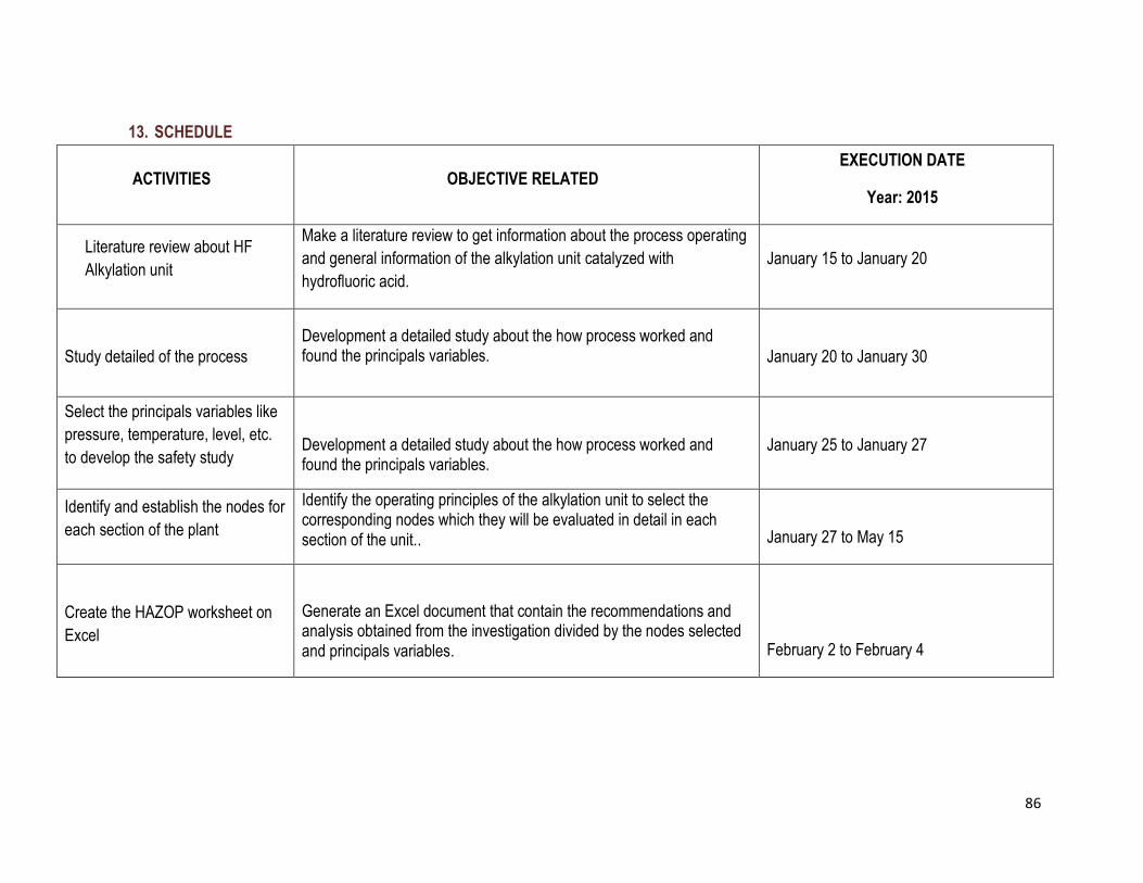
86
13. SCHEDULE
ACTIVITIES OBJECTIVE RELATED EXECUTION DATE
Year: 2015
Literature review about HF
Alkylation unit
Make a literature review to get information about the process operating
and general information of the alkylation unit catalyzed with
hydrofluoric acid.
January 15 to January 20
Study detailed of the process
Development a detailed study about the how process worked and found the principals variables.
January 20 to January 30
Select the principals variables like
pressure, temperature, level, etc.
to develop the safety study
Development a detailed study about the how process worked and found the principals variables.
January 25 to January 27
Identify and establish the nodes for
each section of the plant
Identify the operating principles of the alkylation unit to select the corresponding nodes which they will be evaluated in detail in each section of the unit..
January 27 to May 15
Create the HAZOP worksheet on
Excel
Generate an Excel document that contain the recommendations and analysis obtained from the investigation divided by the nodes selected and principals variables.
February 2 to February 4
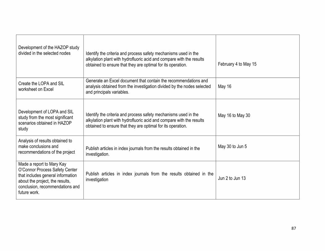
87
Development of the HAZOP study divided in the selected nodes
Identify the criteria and process safety mechanisms used in the alkylation plant with hydrofluoric acid and compare with the results obtained to ensure that they are optimal for its operation.
February 4 to May 15
Create the LOPA and SIL worksheet on Excel
Generate an Excel document that contain the recommendations and analysis obtained from the investigation divided by the nodes selected and principals variables.
May 16
Development of LOPA and SIL study from the most significant scenarios obtained in HAZOP study
Identify the criteria and process safety mechanisms used in the alkylation plant with hydrofluoric acid and compare with the results obtained to ensure that they are optimal for its operation.
May 16 to May 30
Analysis of results obtained to make conclusions and recommendations of the project
Publish articles in index journals from the results obtained in the investigation.
May 30 to Jun 5
Made a report to Mary Kay O’Connor Process Safety Center that includes general information about the project, the results, conclusion, recommendations and future work.
Publish articles in index journals from the results obtained in the investigation
Jun 2 to Jun 13

88
Development a report to Universidad de San Buenaventura based in the results and information about the process.
Publish articles in index journals from the results obtained in the investigation.
July 31 to August 5
14. ABBREVIATIONS AND ACRONYMS
ALKAD: beta-picoline
BBS: Behavior Based Safety
BPD: Barrels equivalent per day
CO: carbon monoxide
CPI: chemical process industries
E: Environmental
ETA: Event Tree Analysis
F: Financial
FCCU: fluid catalytic cracking unit
FTA: Fault Tree Analysis

89
HA: hydroxylamine
HAZAN: Hazard Analysis
HAZOP: Hazard and Operability Study
HF: hydrofluoric acid
HRA: Human Reliability Analysis
IPL: Independent protection layer
IR: Individual Risk
KOH: potassium hydroxide
LEL: element level low
LNG: Liquefied Natural Gas
LOPA: Layer of Protection Analysis
PFD: probability of failure on demand
PFDs: Process Flow Diagrams
PFDG: probability of dangerous failure on demand
PHA: Process Hazard Analysis

90
P&lDs: Piping & Instrument Diagrams
QRA: Quantitative Risk Analysis
RBD: reliability block diagram
RO: Restrictive Orifice
S: Safety
SIL: Safety Integrity Level
SIS’s: safety instrumented systems
SPLs: Safety Protection Layers
TF: tolerable frequency
15. ACKNOWLEDGMENTS
The authors are grateful to Dr. Sam Mannan and Ms.Valerie Green for the opportunity to they gave us to perform this internship at the center, for their support,
understanding and all the lessons learned who gave us during these six months so that this experience was rewarding and will be held with success each of the
objectives. Likewise we want to say thank you to all the members of the Mary Kay O'Connor Process Safety (MKOPSC) especially to Dr. Sonny Sachdeva, Dr. Yi
Liu, Dr. Richart Vazquez and Dr. Chad Mashuga.
Also, we want to say thanks to the Universidad de San Buenaventura-Cartagena for the formation that they gave us during our major and our mentor Dr. Juliana
Puello.
91
Engineer Jorge Espinosa from Ecopetrol S.A for his collaboration, providing information to complete the project and especially for being available to give us
necessary information and each of the engineers who took some time to explain some things about the process that was studied.
Finally we want to say thanks to our parents who gave us their unconditional support, for supporting us financially in this process, to always be there guiding us
and encouraging us at difficult times. Likewise for providing the best legacy than they can give us: education.
16. REFERENCES
Akpabio, E., Neeka J., 2013. Review of Petroleum Refinery Acid Catalyzed Alkylation Processes: A Message to Nigerian Refineries. Petroleum Technology
Development Journal: An International Journal, 3, 84- 97. ISSN 1595-9104
American Institute of Chemical Engineers Guidelines for Hazards Evaluation Procedures. Second Edition with Worked Examples.Copirigh. ISBN 0-8169-0491-X
Barril de petróleo. 2009 copyright Yupirramos. Accessed March 11 2015 < http://sp.depositphotos.com/7970527/stock-illustration-oil-barrel.html>
Bertolini, J., 1992. Hydrofluoric acid: A review of toxicity. The Journal of Emergency Medicine, 10, 163-168
Binghman K. and Goteti P., 2004. Integrating HAZOP and SIL/LOPA analysis: best practice recommendations. The instrumentation system and Automation
Society. Houston Texas. Available on web <http://www.keesofferman.nl/calculators/integrating_hazop_and_sil.pdf> Date: 05/31/2015
Cartagena de Indias – Colombia, n. d. Photograph. Accessed March 12 2015.< http://nodocios.com.ar/sumando-valor-en-universidad-san-buenaventura-
cartagena-de-indias-colombia/>
Centers for Disease Control and Prevention. NIOSH Pocket Guide to Chemical Hazards: Hydrogen Fluoride. Date: 04-01-2015
Crowl D. and Louvar J.,2011. Chemical Process Safety Fundamentals with Application.ThirdEdition. Prentice Hall. ISBN 0-13-138226-8
Ecopetrol S.A., 2014. Manual de descripción del proceso de la unidad de alquilacion HF y TAE (U-044). Cartagena: Refineria Cartagena S.A (Reficar S.A)
Ecopetrol, 2015 copyright ACIPET.Accessed March 12 2015.http://petroguia.com.co/empresademo/ecopetrol-3/

92
EPA united States Environmental Protection Agency. Hydrogen Fluoride (Hydrofluric Acid). Revised Date [January 2000].
[http://www.epa.gov/ttnatw01/hlthef/hydrogen.html] Date: 07-01-2015
DuPont.Comparison of H2SO4 & HF Alkylation Process Technologies. [http://www.dupont.com/content/dam/assets/products-and-services/consulting-services-
process-technologies/articles/documents/H2SO4_vs._HF.pdf] Date: 04-02-2015
Fahim M., Alsahhaf T. and Elkilano A., 2010.Fundamentals of Petroleum Refining. Chapter 14 - Safety in Petroleum Refineries, 357-376. Department of Chemical
Engineering, Kuwait University, Khaldeya, Kuwait
Flanker, 2006.The hazard symbol for highly toxic substances according to directive 67/548/EWG by European Chemical
Bureau.http://commons.wikimedia.org/wiki/File:Hazard_TT.svg. Date: 04-01-2015
Gad SE, Sullivan DW. (2014). Encyclopedia of Toxicology: Hydrofluoric acid (Third edition). Elsevier, Inc
Kletz T., 2006. Hazop and Hazan. Identifying and assessing process industry hazards. Fourth Edition.Institution of Chemical Engineers (IChemE). ISBN:
9780852955062
Lockwood J., 2013. Process Safety Management Fundamentals.Texas A&M University. College Station
Matthias M., 2006. The hazard symbol for corrosive substances according to directive 67/548/EWG by the European Chemicals
Bureau.http://commons.wikimedia.org/wiki/File:Hazard_C.svg. Date: 04-01-2015
Meyer E. Chemistry of Hazardous Materials. Regents/Prentice Hall. Englewood Cliffs, New Jersey OPEN CHEMESTRY DATABASE. Hydrofluoric Acid. Date: 04-
01-2015
Peterson R., 1998. Alkylate is key for cleaner burning gasoline. STRATCO, Inc. [https://web.anl.gov/PCS/acsfuel/preprint%20archive/Files/41_3_ORLANDO_08-
96_0916.pdf] Date: 04-02-2015
Producción Grupo Empresarial Alcanza los 750 mil barriles por Dia en junio. 2014 copyright wpadimn. Accessed March 11 2015 <
http://www.ecopetrol.com.co/wps/portal/es/ecopetrol-web/>
Refinería de Cartagena. 2015 COLPRENSA. Accessed March 11 2015 < http://www.elcolombiano.com/refineria-de-cartagena-iniciaria-operaciones-en-segundo-
semestre-de-2015-ecopetrol-DY1414306>
93
Ricardo R., 2011, Petroleum Refining. Atlantic international university. Honolulu, Hawaii. SIGMA-ALDRICH. 339261 - Hydrofluoric acid. Date: 03-30-2015
Simpson M y Kester M. (2007).Hydrofluric acid alkylation. ABB and ConocoPhilips develop a critical new process analysis tool. Texas: ConocoPhillips
UNC Environment, Health & Safety.Hydrofluoric Acid – Chemical Safety Information. Date:04-01-2015
UNITED STATES DEPARTMENT OF LABOR. OSHA Occupational Chemical Database: Hydrogen Fluoride. Date: 04-01-2015
U.S. EPA.Hydrogen Fluoride Study. Report to Congress, Section 112. Clean Air Act As Amended
Universidad de San Buenaventura Cartagena, n. d. Photograph. Accessed March 12 2015.http://www.guiaacademica.com/sitios/s408/index.aspx?id=408
Xueqi X, Guoying Z, Jianzhong C y Suojiang Z. (2012). Isobutane alkylation using acidic ionic liquid catalysts. China: Department of chemestry, Tianjin University.

94
17. LIST OF ANNEXES
NODE DESCRIPTION NODE PROCESS PARAMETERS DEVIATION POSSIBLE CAUSE EXISTING SAFEGUARDS CONSEQUENCES S F R RECOMMENDATION
1.1 .1
Temperature Indicator
with electrical signal in
the inlet stream (TI
4152)
Decrease in the
separation time
between
hydrocarbon and
water.
The Temperature Indicator (TI 4152)
works with a flow valve control in the
inlet stream.
Change the TI 4152 for a Temperature
Indicator Alarm Control to ensure the
correct control of the temperature and
avoid possible fails
1.1.2 Same as 1.1.1
Injection of N2
due to the less
pressure in the
Surge Drum (D-
201)
Constantly monitoring of the PIC 4007
and valve PV-4007A for avoid possibles
ruptures and other damages that can
affect the separation
1.1.3
Stream
temperature from
P-201A/B is cooler
than normal
TI 4008Same as 1.1.1 and
1.1.21 1 1-L
Consider install a Temperature
Indicator Control in the stream from P-
201A/B to avoid possibles fails and
losses of the olefins
1.1.4
TE 4152 failed and
send a wrong
signal to the TI
4152 due to
malfunctions
Same as 1.1.1 Same as 1.1.1 and
1.1.21 1 1-L
Install an additional temperature
sensor (TE) with an electrical signal
after of the TE 4152.
1.1.5
Decrease in the
pressure tank (<75
psig) due to
external events
Pressure Indicator
Control (PIC 4007)
Increase in the N2
flow into the tank 1 1 1-L
Install an additional pressure
transmitter (PT) conect with the PIC
4007 to control the process and the
operational profile
Constantly monitoring of the PIC 4007
for avoid possible damages and
deviations of the process due to
external events
1.2.1
Temperature of
inlet is higher than
normal (>110°F)
Temperature Indicator
with electrical signal in
the inlet stream (TI
4152)
Separation time
between
hydrocarbon and
water is higher.
1 1 1-L Same as 1.1.1
1.2.2
Stream
temperature from
P-201AA/B is
higher than normal
Same as 1.2.1 Same as 1.2.1 1 5 5-M Same as 1.1.3
1.2.3
TE 4152 failed and
send a wrong
signal to the TI
4152
Same as 1.2.1 Same as 1.2.1 1 1 1-L Same as 1.1.4
1.2.4
Increase in the
pressure tank due
to generation
vapor (>75psig)
Same as 1.1.5
Air pollution due
to an increase in
the gas stream to
the TEA system.
2 3 6-M Same as 1.1.5.
1 1 1-L
Temperature of
inlet is cooler than
normal (<110°F)
LESS
TEMPERATURE
HAZOP WORKSHEET - ANNEX 1 Project Title: Application of HAZOP, LOPA and SIL to the alkylation unit catalyzed with hydrofluoric acid
Study Section: Selective Hydrogenation Process: The objective is the removal of diolefins and light fractions of the olefins stream
HAZOP Team: Figueroa Stefanny, Lombana Stefany and Ruiz Ingry Meeting days: All days of Febrary to June
HIGH
FEED SURGE DRUM
D-201 1
Date: Febrary to June Page 1 of 1
Annex 1 Application of HAZOP methodology to Selective Hydrogenation Section
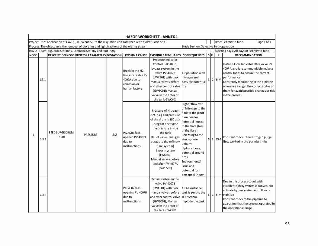
95
NODE DESCRIPTION NODE PROCESS PARAMETERS DEVIATION POSSIBLE CAUSE EXISTING SAFEGUARDS CONSEQUENCES S F R RECOMMENDATION
1.3.1
Break in the N2
line after valve PV
4007A due to
corrosion or
human factors
Pressure Indicator
Control (PIC 4007);
bypass system in the
valve PV 4007B
(LWXS01) with two
manual valves before
and after control valve
(GWSC01); Manual
valve in the enter of
the tank GWCY01
Air pollution with
nitrogen and
possible potential
fire
3 2 6-M
Install a Flow Indicator after valve PV
4007 A and is recommendable make a
control loops to ensure the correct
performance
Constantly monitoring in the pipeline
where we can get the correct status of
them for avoid possible changes or risk
in the process
1.3.3
PIC 4007 fails
opened PV 4007A
due to
malfunctions
Pressure of Nitrogen
is 95 psig and pressure
of the drum is 180 psig
using for decreasse
the pressure inside
the tank
Relief valve (Fuel gas
purges to the refinery
flare system)
Bypass system
(LWCS01)
Manual valves before
and after PV 4007A
(GWCS01)
Higher flow rate
of Nitrogen to the
flare to the plant
flare header.
Potential impact
to the flare (loss
of the flare).
Releasing to the
atmosphere
unburnt
Hydrocarbons,
potential ground
fires.
Environmental
issue and
potential for
personnel injury.
5 3 15-SConstant check if the Nitrogen purge
flow worked in the permits limits
1.3.4
PIC 4007 fails
opening PV 4007B
due to
malfunctions
Bypass system in the
valve PV 4007B
(LWXS01) with two
manual valves before
and after control valve
(GWSC01); Manual
valve in the enter of
the tank GWCY01
All Gas into the
tank is sent to the
TEA system.
Implode the tank
5 1 5-M
Due to the process count with
excellent safety system is convenient
activate bypass system until flow is
stabilize
Constant check to the pipeline to
guarantee that the process operated in
the operational range
PRESSURE FEED SURGE DRUM
D-201 1
HAZOP WORKSHEET - ANNEX 1 Project Title: Application of HAZOP, LOPA and SIL to the alkylation unit catalyzed with hydrofluoric acid
Study Section: Selective Hydrogenation Process: The objective is the removal of diolefins and light fractions of the olefins stream
HAZOP Team: Figueroa Stefanny, Lombana Stefany and Ruiz Ingry Meeting days: All days of Febrary to June
LESS
Date: Febrary to June Page 1 of 1
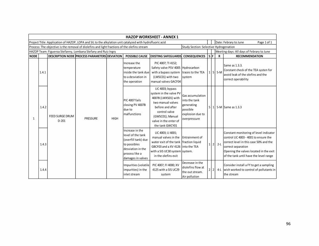
96
NODE DESCRIPTION NODE PROCESS PARAMETERS DEVIATION POSSIBLE CAUSE EXISTING SAFEGUARDS CONSEQUENCES S F R RECOMMENDATION
1.4.1
Increase the
temperature
inside the tank due
to a desviation in
the operation
PIC 4007; TI 4152;
Safety valve PSV 4005
with a bypass system
(LWSC01) with two
manual valves GACF04
Hydrocarbon
traces to the TEA
system
1 5 5-M
Same as 1.3.3.
Constant check of the TEA systen for
avoid leak of the olefins and the
correct operability
1.4.2
PIC 4007 fails
closing PV 4007B
due to
malfunctions
LIC 4003; bypass
system in the valve PV
4007B (LWXS01) with
two manual valves
before and after
control valve
(GWSC01); Manual
valve in the enter of
the tank GWCY01
Gas accumulation
into the tank
generating
possible
explosion due to
overpressure
5 1 5-M Same as 1.3.3
1.4.3
Increase in the
level of the tank
(overfill tank) due
to possibles
desviation in the
process like a
damages in valves
LIC 4003; LI 4001;
manual valves in the
water exit of the tank
GBCF03 and a XV 4126
with a SIS UC30 system
in the olefins exit
Entrainment of
fraction liquid
into the TEA
system.
1 2 2-L
Constant monitoring of level indicator
control LIC 4003 - 4001 to ensure the
correct level in this case 50% and the
correct separation
Opening the valves located in the exit
of the tank until have the level range
1.4.4
Impurities (volatile
impurities) in the
inlet stream
PIC 4007; FI 4000; XV
4125 with a SIS UC29
system
Decrease in the
diolefins flow at
the out stream.
Air pollution
2 2 4-L
Consider install a FY to get a sampling
wich worked to control of pollutants in
the stream
PRESSUREFEED SURGE DRUM
D-201 1
HAZOP WORKSHEET - ANNEX 1 Project Title: Application of HAZOP, LOPA and SIL to the alkylation unit catalyzed with hydrofluoric acid
Study Section: Selective Hydrogenation Process: The objective is the removal of diolefins and light fractions of the olefins stream
HAZOP Team: Figueroa Stefanny, Lombana Stefany and Ruiz Ingry Meeting days: All days of Febrary to June
HIGH
Date: Febrary to June Page 1 of 1
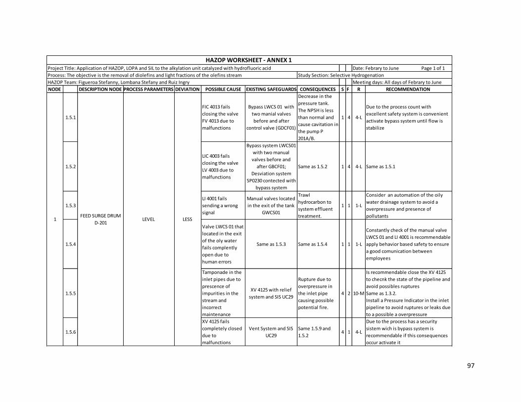
97
NODE DESCRIPTION NODE PROCESS PARAMETERS DEVIATION POSSIBLE CAUSE EXISTING SAFEGUARDS CONSEQUENCES S F R RECOMMENDATION
1.5.1
FIC 4013 fails
closing the valve
FV 4013 due to
malfunctions
Bypass LWCS 01 with
two manial valves
before and after
control valve (GDCF01)
Decrease in the
pressure tank.
The NPSH is less
than normal and
cause cavitation in
the pump P
201A/B.
1 4 4-L
Due to the process count with
excellent safety system is convenient
activate bypass system until flow is
stabilize
1.5.2
LIC 4003 fails
closing the valve
LV 4003 due to
malfunctions
Bypass system LWCS01
with two manual
valves before and
after GBCF01;
Desviation system
SP0230 contected with
bypass system
Same as 1.5.2 1 4 4-L Same as 1.5.1
1.5.3
LI 4001 fails
sending a wrong
signal
Manual valves located
in the exit of the tank
GWCS01
Trawl
hydrocarbon to
system effluent
treatment.
1 1 1-L
Consider an automation of the oily
water drainage system to avoid a
overpressure and presence of
pollutants
1.5.4
Valve LWCS 01 that
located in the exit
of the oly water
fails complently
open due to
human errors
Same as 1.5.3 Same as 1.5.4 1 1 1-L
Constantly check of the manual valve
LWCS 01 and LI 4001 is recommendable
apply behavior based safety to ensure
a good comunication between
employees
1.5.5
Tamponade in the
inlet pipes due to
prescence of
impurities in the
stream and
incorrect
maintenance
XV 4125 with relief
system and SIS UC29
Rupture due to
overpressure in
the inlet pipe
causing possible
potential fire.
4 2 10-M
Is recommendable close the XV 4125
to checnk the state of the pipeline and
avoid possibles ruptures
Same as 1.3.2.
Install a Pressure Indicator in the inlet
pipeline to avoid ruptures or leaks due
to a possible a overpressure
1.5.6
XV 4125 fails
completely closed
due to
malfunctions
Vent System and SIS
UC29
Same 1.5.9 and
1.5.2 4 1 4-L
Due to the process has a security
sistem wich is bypass system is
recommendable if this consequences
occur activate it
LEVEL 1FEED SURGE DRUM
D-201LESS
HAZOP WORKSHEET - ANNEX 1 Project Title: Application of HAZOP, LOPA and SIL to the alkylation unit catalyzed with hydrofluoric acid
Study Section: Selective Hydrogenation Process: The objective is the removal of diolefins and light fractions of the olefins stream
HAZOP Team: Figueroa Stefanny, Lombana Stefany and Ruiz Ingry Meeting days: All days of Febrary to June
Date: Febrary to June Page 1 of 1

98
NODE DESCRIPTION NODE PROCESS PARAMETERS DEVIATION POSSIBLE CAUSE EXISTING SAFEGUARDS CONSEQUENCES S F R RECOMMENDATION
1.6.1
Tamponade in the
olefins exit piping
due to prescence of
impurities
LIC 4003; LI 4001; Safety
valve PSV 4005 with a bypass
system LWSC01 and two
manual valves before and
after safety valve (GWCY01
and GACF04)
Rupture due to
overpressure in the outlet
pipe causing possible
potential fire. The NPSH is
less than requested and
cause cavitation in the
pump P 201A/B.
4 2 8-M
Activate a PSV valve to stabilize the flow and
considere install a flow indicator before the
pumps P 201A/B to avoid possibles
cavitations due to a increase or decrease of
the flow Periodic
maintenance to the pipeline and reporting
the real state
1.6.2
LIC 4003 fails
opening the valve LV
4003 due to
malfunctions
Bypass system LWCS01 with
two manual valves before
and after GBCF01;
Desviation system SP0230
contected with bypass
system
Entrainment of fraction
liquid into the TEA
system.
Overpressure in the tank
causing possible
explosion.
5 2 10-M
Activate a PSV valve to stabilize the flow and
considere install a flow indicator before the
pumps P 201A/B to avoid possibles
cavitations due to a increase or decrease of
the flow. Considere install a Flow Indicator
Alarm before XV 4125 to control the flow that
enter and avoid a overpressure and increase
of the temperature
1.6.3
Tamponade in the
oily water drain line
due to prescence of
impurities
LIC 4003; LI 4001; Safety
valve PSV 4005 with a bypass
system LWSC01 and two
manual valves before and
after safety valve (GWCY01
and GACF04)
Same as 1.6.2.
Entrainment of oily water
in the process stream.
3 3 9-M
Install a Flow indicator in the oily water drain
line to ensure the correct separation and
avoid of presence of possible contaminants
1.6.4
FIC 4013 fails
opening the valve FV
4013 due to
malfunctions
Bypass LWCS 01 with two
manial valves before and
after control valve (GDCF01)
Same as 1.6.2. 5 1 5-M
Due to the process count with excellent
safety system is convenient activate bypass
system until flow is stabilize
1.6.5
Increase in the
olefins and diolefins
flow that enter to
tank
XV 4125; LIC 4003; FIC 4013Same as 1.6.2.
Economic losses5 2 10-M
Install a flow indicator control which works
with valve XV 4125 to ensure the correct
separation and avoid of presence of possible
contaminants
1.6.6
LI 4001 fails due to
malfunctions
sending a wrong
signal
LIC 4003; Manual valves
located in the exit of the
tank GWCS01
Same as 1.6.3 3 1 3-M Same as 1.5.4
1.6.7
XV 4126 fails
completely closed
due to malfunctions
No safeguard Same as 1.6.1 5 2 10-M
Install a flow indicator before the pumps P
201A/B which works in a loop with valve XV
4126.
1.6.8
XV 4125 fails
completely open
due to malfunctions
Vent System and SIS UC29 Same as 1.6.2 5 2 10-M
Due to the process has a security sistem wich
is bypass system is recommendable if this
consequences occur activate it
FEED SURGE DRUM
D-2011 LEVEL HIGH
HAZOP WORKSHEET - ANNEX 1 Project Title: Application of HAZOP, LOPA and SIL to the alkylation unit catalyzed with hydrofluoric acid
Study Section: Selective Hydrogenation Process: The objective is the removal of diolefins and light fractions of the olefins stream
HAZOP Team: Figueroa Stefanny, Lombana Stefany and Ruiz Ingry Meeting days: All days of Febrary to June
Date: Febrary to June Page 1 of 1
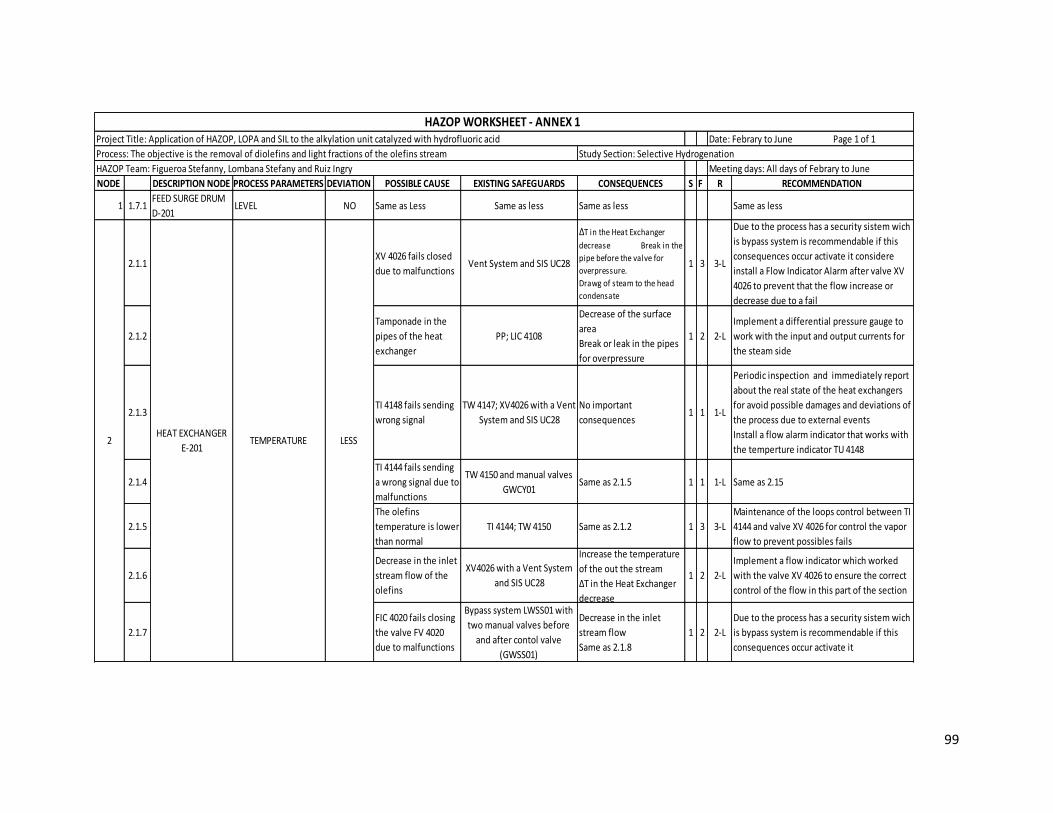
99
NODE DESCRIPTION NODE PROCESS PARAMETERS DEVIATION POSSIBLE CAUSE EXISTING SAFEGUARDS CONSEQUENCES S F R RECOMMENDATION
1 1.7.1FEED SURGE DRUM
D-201LEVEL NO Same as Less Same as less Same as less Same as less
2.1.1XV 4026 fails closed
due to malfunctionsVent System and SIS UC28
∆T in the Heat Exchanger
decrease Break in the
pipe before the valve for
overpressure.
Drawg of steam to the head
condensate
1 3 3-L
Due to the process has a security sistem wich
is bypass system is recommendable if this
consequences occur activate it considere
install a Flow Indicator Alarm after valve XV
4026 to prevent that the flow increase or
decrease due to a fail
2.1.2
Tamponade in the
pipes of the heat
exchanger
PP; LIC 4108
Decrease of the surface
area
Break or leak in the pipes
for overpressure
1 2 2-L
Implement a differential pressure gauge to
work with the input and output currents for
the steam side
2.1.3TI 4148 fails sending
wrong signal
TW 4147; XV4026 with a Vent
System and SIS UC28
No important
consequences 1 1 1-L
Periodic inspection and immediately report
about the real state of the heat exchangers
for avoid possible damages and deviations of
the process due to external events
Install a flow alarm indicator that works with
the temperture indicator TU 4148
2.1.4
TI 4144 fails sending
a wrong signal due to
malfunctions
TW 4150 and manual valves
GWCY01Same as 2.1.5 1 1 1-L Same as 2.15
2.1.5
The olefins
temperature is lower
than normal
TI 4144; TW 4150 Same as 2.1.2 1 3 3-L
Maintenance of the loops control between TI
4144 and valve XV 4026 for control the vapor
flow to prevent possibles fails
2.1.6
Decrease in the inlet
stream flow of the
olefins
XV4026 with a Vent System
and SIS UC28
Increase the temperature
of the out the stream
∆T in the Heat Exchanger
decrease
1 2 2-L
Implement a flow indicator which worked
with the valve XV 4026 to ensure the correct
control of the flow in this part of the section
2.1.7
FIC 4020 fails closing
the valve FV 4020
due to malfunctions
Bypass system LWSS01 with
two manual valves before
and after contol valve
(GWSS01)
Decrease in the inlet
stream flow
Same as 2.1.8
1 2 2-L
Due to the process has a security sistem wich
is bypass system is recommendable if this
consequences occur activate it
TEMPERATURE 2HEAT EXCHANGER
E-201 LESS
HAZOP WORKSHEET - ANNEX 1 Project Title: Application of HAZOP, LOPA and SIL to the alkylation unit catalyzed with hydrofluoric acid
Study Section: Selective Hydrogenation Process: The objective is the removal of diolefins and light fractions of the olefins stream
HAZOP Team: Figueroa Stefanny, Lombana Stefany and Ruiz Ingry Meeting days: All days of Febrary to June
Date: Febrary to June Page 1 of 1

100
NODE DESCRIPTION NODE PROCESS PARAMETERS DEVIATION POSSIBLE CAUSE EXISTING SAFEGUARDS CONSEQUENCES S F R RECOMMENDATION
2.2.1XV 4026 fails opened
due to malfunctionsVent System and SIS UC28
∆T in Heat Exchanger
increase causing a higher
temperature in the
olefins stream.
Economic losses due to
unnecesary use of steam
rate.
Increase in the pressure.
Increase in the condenser
level.
2 2 4-L Same as 2.1.1
2.2.2
The steam
temperature is
higher than
operating
temperature (>307
°F)
Same as 2.1.2
∆T in Heat Exchanger
increase causing a higher
temperature in the
olefins stream.
Increase in the pressure.
1 2 2-L Same as 2.1.2
2.2.3
The olefins
temperature is
higher than normal
Same as 2.1.7∆T in Heat Exchanger
increase1 3 3-L Same as 2.1.5
2.2.4
Increase in the inlet
stream flow of the
olefins
XV4026 with a Vent System
and SIS UC28
Same as 2.2.3
Decrease the temperature
in the out stream.
1 2 2-L Same as 2.1.6
2.2.5
FIC 4020 fails
opening the valve
FV4020 due to
malfunctions
Same as 2.1.7Increase in the inlet
stream flow. Same as 2.2.41 2 2-L Same as 2.1.7
TEMPERATURE
HAZOP WORKSHEET - ANNEX 1 Project Title: Application of HAZOP, LOPA and SIL to the alkylation unit catalyzed with hydrofluoric acid
Study Section: Selective Hydrogenation Process: The objective is the removal of diolefins and light fractions of the olefins stream
HAZOP Team: Figueroa Stefanny, Lombana Stefany and Ruiz Ingry Meeting days: All days of Febrary to June
HIGHHEAT EXCHANGER
E-201 2
Date: Febrary to June Page 1 of 1

101
NODE DESCRIPTION NODE PROCESS PARAMETERS DEVIATION POSSIBLE CAUSEEXISTING SAFEGUARDS CONSEQUENCES S F R RECOMMENDATION
3.1.1
The temperature
of inlet stream is
lower than
operating
temperature.
Same as 2.1.7
Lower production of
steam in the
condenser.
More production of
liquid phase in the
drum (Increase in the
out flow rate).
1 4 4-L
Periodic maintenance to the Heat
Exchanger E-201 to ensure the correct
temperature to prevent possible fails
that can change the operational
profile
3.1.2
Increase of the ∆T
due to decrease in
the inlet
temperature of
diolefins and
olefins in the heat
exchanger E-201
TI 4148; TI 4133; TI
4145Same as 3.1.1 1 4 4-L Same as 3.1.1
3.1.3
XV 4026 fails
closed decreasing
the steam flow
rate.
GWCS 01; Vent
System and SIS
UC28
Same as 3.1.1 1 4 4-L
Maintenance to the valve XV 4026 to
prevent ruptures, leaks or hold for
corrosion or external events and
contamination of the other streams of
the process
3.2.1
The temperature
of inlet stream is
higher than
operating
temperature.
PSV 4105; GWCS
01
Increase in the
pressure causing more
production of steam.
Increase in the flow
rate of vapour in the
inlet of the heat
exchanger E-201.
1 3 3-L Same as 3.1.1
3.2.2
Decrease of the ∆T
due to increase in
the inlet
temperature of
diolefins and
olefins in the heat
exchanger E-201
TI 4148; TI 4133; TI
4145
Same as 3.2.1.
More production of
steam in the
condenser and lower
production of liquid
phase.
1 5 5-M Same as 3.1.1
3.2.3
XV 4026 fails
opened due to
malfunctions
GWCS 01; Vent
System and SIS
UC28
Economic losses due to
unnecesary use of
steam.
2 4 8-M Same as 3.1.3
3CONDENSER
D-204
HAZOP WORKSHEET - ANNEX 1 Project Title: Application of HAZOP, LOPA and SIL to the alkylation unit catalyzed with hydrofluoric acid
Study Section: Selective Hydrogenation Process: The objective is the removal of diolefins and light fractions of the olefins stream
HAZOP Team: Figueroa Stefanny, Lombana Stefany and Ruiz Ingry Meeting days: All days of Febrary to June
Date: Febrary to June Page 1 of 1
LESS
HIGH
TEMPERATURE
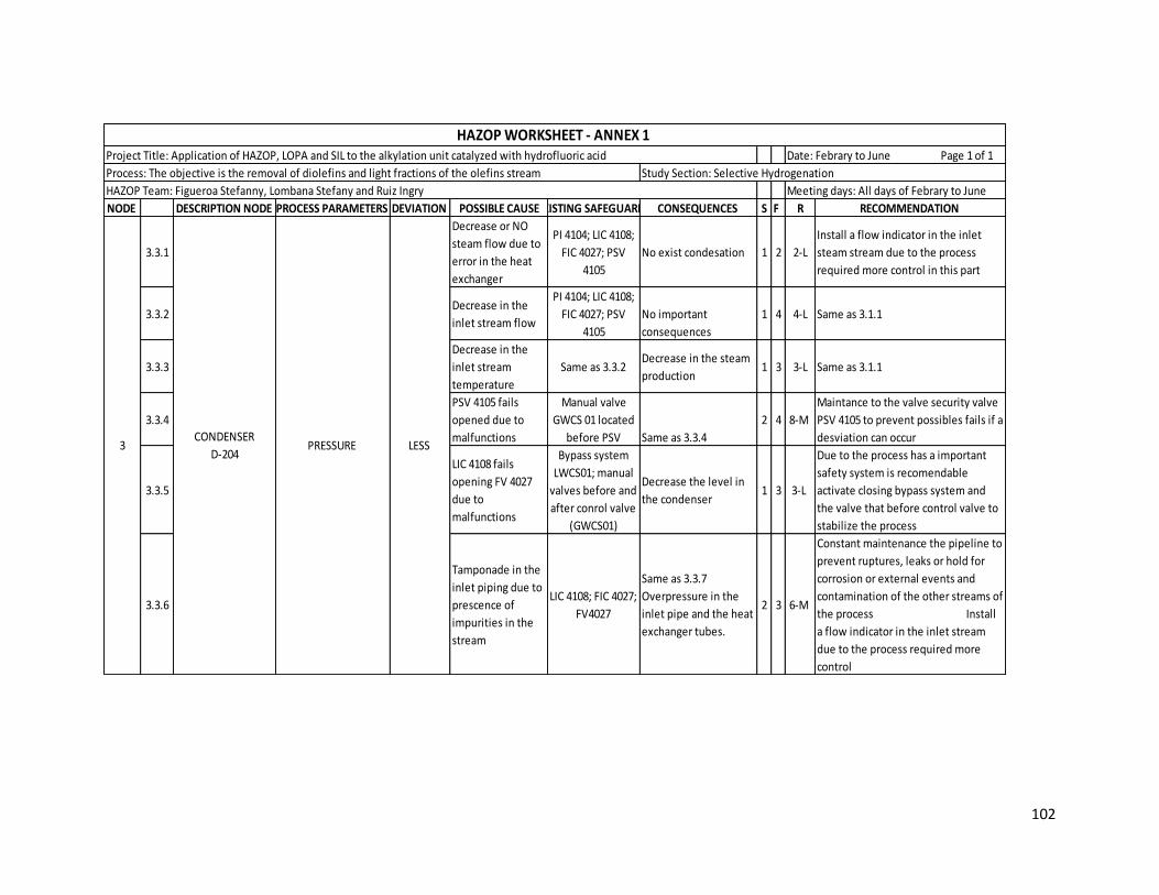
102
NODE DESCRIPTION NODE PROCESS PARAMETERS DEVIATION POSSIBLE CAUSEEXISTING SAFEGUARDS CONSEQUENCES S F R RECOMMENDATION
3.3.1
Decrease or NO
steam flow due to
error in the heat
exchanger
PI 4104; LIC 4108;
FIC 4027; PSV
4105
No exist condesation 1 2 2-L
Install a flow indicator in the inlet
steam stream due to the process
required more control in this part
3.3.2Decrease in the
inlet stream flow
PI 4104; LIC 4108;
FIC 4027; PSV
4105
No important
consequences
1 4 4-L Same as 3.1.1
3.3.3
Decrease in the
inlet stream
temperature
Same as 3.3.2Decrease in the steam
production 1 3 3-L Same as 3.1.1
3.3.4
PSV 4105 fails
opened due to
malfunctions
Manual valve
GWCS 01 located
before PSV Same as 3.3.4
2 4 8-M
Maintance to the valve security valve
PSV 4105 to prevent possibles fails if a
desviation can occur
3.3.5
LIC 4108 fails
opening FV 4027
due to
malfunctions
Bypass system
LWCS01; manual
valves before and
after conrol valve
(GWCS01)
Decrease the level in
the condenser 1 3 3-L
Due to the process has a important
safety system is recomendable
activate closing bypass system and
the valve that before control valve to
stabilize the process
3.3.6
Tamponade in the
inlet piping due to
prescence of
impurities in the
stream
LIC 4108; FIC 4027;
FV4027
Same as 3.3.7
Overpressure in the
inlet pipe and the heat
exchanger tubes.
2 3 6-M
Constant maintenance the pipeline to
prevent ruptures, leaks or hold for
corrosion or external events and
contamination of the other streams of
the process Install
a flow indicator in the inlet stream
due to the process required more
control
PRESSURE 3CONDENSER
D-204
HAZOP WORKSHEET - ANNEX 1 Project Title: Application of HAZOP, LOPA and SIL to the alkylation unit catalyzed with hydrofluoric acid
Study Section: Selective Hydrogenation Process: The objective is the removal of diolefins and light fractions of the olefins stream
HAZOP Team: Figueroa Stefanny, Lombana Stefany and Ruiz Ingry Meeting days: All days of Febrary to June
Date: Febrary to June Page 1 of 1
LESS

103
NODE DESCRIPTION NODE PROCESS PARAMETERS DEVIATION POSSIBLE CAUSE EXISTING SAFEGUARDS CONSEQUENCES S F R RECOMMENDATION
3.4.1
XV 4026 fails
opened due to
malfunctions
Manual valves GBCF01
GWCS 01; Vent
System PSV 4105; PI
4104
Explosion in the
condenser due to
overpressure inside
the vessel.
3 2 6-M
Close the manual valve that located
before the control valve until process
is stabilize
3.4.2
LIC 4108 fails
closing FV 4027
due to
malfunctions
Bypass system
LWCS01; manual
valves before and
after conrol valve
(GWCS01)
Increase in the level
causing dawg of
condensate to the
steam line.
1 2 2-L
Due to the process has a important
safety system is recomendable
activate closing bypass system and
the valve that before control valve to
stabilize the process
3.4.3
Increase in the
inlet flow stream
due to external
events
LIC 4108 Same as 3.4.2 1 4 4-L
Install a flow indicator in the inlet
steam stream due to the process
required more control in this part
3.4.4PSV 4105 fails
closed.
Manual valve located
before the safety
valve GWCS 01
Same as 3.4.1 3 2 6-M Same as 3.3.6
3.4.5
Increase in the
inlet stream
temperature due
to malfunctions in
the heat
exchanger
PI 4104
More production of
steam in the
condenser.
1 4 4-L
Periodic maintenance to the Heat
Exchanger E-201 to ensure the correct
temperature to prevent possible fails
that can change the operational
profile
3.4.6
Tamponade in the
exit piping due to
prescence of
impurities in the
stream
FIC 4027; LIC 4108; PI
4104 Same as 3.4.2 2 3 6-M
Constant maintenance the pipeline to
prevent ruptures, leaks or hold for
corrosion or external events and
contamination of the other streams of
the process
PRESSURE 3CONDENSER
D-204
HAZOP WORKSHEET - ANNEX 1 Project Title: Application of HAZOP, LOPA and SIL to the alkylation unit catalyzed with hydrofluoric acid
Study Section: Selective Hydrogenation Process: The objective is the removal of diolefins and light fractions of the olefins stream
HAZOP Team: Figueroa Stefanny, Lombana Stefany and Ruiz Ingry Meeting days: All days of Febrary to June
Date: Febrary to June Page 1 of 1
HIGH

104
NODE DESCRIPTION NODE PROCESS PARAMETERS DEVIATION POSSIBLE CAUSE EXISTING SAFEGUARDS CONSEQUENCES S F R RECOMMENDATION
3.5.1
LIC 4108 fails
opening FV 4027
due to
malfunctions
Bypass system LWCS01;
manual valves before
and after conrol valve
(GWCS01)
Parcial condenser,
disminution of the
temperature of olefin
outside of E-201
1 4 4-L
Close the manual valve that located
before the control valve until process
is stabilize
3.5.2
FIC 4027 fails
opening FV 4027
due to
malfunctions
Bypass system LWCS01
with two manual valves
GWCS01 ; FE 4027Same as 3.5.1
1 2 2-L
Due to the process has a security
sistem wich is bypass system is
recommendable closing if this
consequences occur activate it
3.5.3
XV 4026 fails
closed due to
malfunctions
Manual valves GBCF01
GWCS 01; Vent System
PSV 4105; PI 4104
Disminution of the
temperature of olefin
oustide of E-201
1 4 4-L Same as 3.5.2
3.5.4
The olefins
temperature is
high normal / The
inlet stream of the
D-204 is liquid-
vapour phase
TI 4144; LIC 4108; FIC
4027 Parcial condenser 1 3 3-L
Install a valve than worked with the TI
4144 if is necessary increase or
decrease the flow and control the
variables like temperature, presure
and flow
3.6.1
Increase in the
inlet stream to D-
204 due to
malfunctions in
the heat
exchanger
LIC 4108; FIC 4027;
FV4027
Decreased heat
transfer.
Overpressure in the D-
204 and E-201.
Liquid draw to the
steam inlet.
Acumulation of the
water condensate in
the E-201
3 1 3-L
Install a Flow Control in the inlet of
the D-204 to check the correct flow
into the tank
3.6.2
LIC 4108 fails
closing the valve
FV 4027
Bypass system LWCS01;
manual valves before
and after conrol valve
(GWCS01)
Same as 3.6.1 3 1 3-L
Due to the process has a important
safety system is recomendable
activate opening bypass system and
the valve that before control valve to
stabilize the process
3.6.3
XV 4026 fails
opened due to
malfunctions
Manual valves GBCF01
GWCS 01; Vent System
PSV 4105; PI 4104
Overpressure in the D-204 and E-2013 1 3-L Same as 3.6.2
3.6.4
FIC 4027 fails
closing the valve
FV 4027
Bypass system LWCS01
with two manual valves
GWCS01 ; FE 4027Same as 3.6.1
3 1 3-L
Due to the process has a security
sistem wich is bypass system is
recommendable opening if this
consequences occur activate it
3.7.1 NO Same as Less
LEVEL
HAZOP WORKSHEET - ANNEX 1 Project Title: Application of HAZOP, LOPA and SIL to the alkylation unit catalyzed with hydrofluoric acid
Study Section: Selective Hydrogenation Process: The objective is the removal of diolefins and light fractions of the olefins stream
HAZOP Team: Figueroa Stefanny, Lombana Stefany and Ruiz Ingry Meeting days: All days of Febrary to June
CONDENSER
D-2043
HIGH
LESS
Date: Febrary to June Page 1 of 1

105
NODE DESCRIPTION NODE PROCESS PARAMETERS DEVIATION POSSIBLE CAUSE EXISTING SAFEGUARDS CONSEQUENCES S F R RECOMMENDATION
4.1.1
Decrease in the
temperature in the
inlet stream of the
reactors 201/202
(< 175⁰F)
TIC 4022; TIC 4023; TI
4044
Wrong operation in
the reactor due to
differents process
conditions.
Promote the
undesirable reactions
decreasing the
lifetime of the
2 3 6-M
Constant monitoring to the operation
conditions and equipments to
prevent ruptures, leaks or hold for
corrosion or external events and
contamination of the other streams of
the process
4.1.2
Decrease in the
hydrogenation
reactions
TI 4043 A.B.C; TI 4044;
TAHH 4043
A.B.C/4042/4044; TI
4053A.B.C; TI 4054; TAHH
4053 A.B.C/4054/4052.
Promote the
undesirable reactions
decreasing the
lifetime of the
catalyst. Economic
losses due to decrease
in the desirable
(olefins).
3 2 6-M Same as 4.1.1
4.1.3
Increase in the non-
exhotermic
undesirable
reaction
Same as 4.1.2.
PI 4038; PI 4048.
Decrease in the
lifetime of the
catalyst.
Production of
undesirable
compounds
2 2 4-L Same as 4.1.1
4.1.4
No reactions due
to damages in the
catalyst
Same as 4.1.3
Economic losses due to
decrease in the
desirable (olefins).
3 2 6-M Same as 4.1.1
4.1.5
PSV 4037 or PSV
4047 fail opened
decreasing the
pressure in the
reactor
PI 4038; PI 4048; GACF
04; GBCF 03; GBCF 01
Same as 4.1.1.
Air pollution 3 2 6-M
Same as 4.1.1 .
Periodic maintenance to the safety
valve PSV 4037/4047 to prevent fails
if a deviation can occur
4.1.6
The inlet stream
has different
composition
FY 4014A/B.
Same as 4.1.2
3 2 6-M
Install a FY in the inlet stream to
prevent precence of contaminants
that can affect the process
4.1.7
The ratio
Hydrogen/diolefin
s is less than
normal
Same as 4.1.6
Decrease the all
reaction causing
decrease in the heat
produced.
2 2 4-L
Periodic monitoring to the results of
FY 4014A/B to prevent prescence of
contaminants that can affect the
process
4.1.8 Decrease in the
catalyst activity
Same as 4.1.2.
PDI 4041 /4051
Decrease in the
hydrogenation
reaction.
3 2 6-M
Periodic reactivation of catalyst to
ensure the correct convertion and the
reaction time
4.1.9
Increase in the
fresh charge to the
reactor
GBCF01 with bypass
system LWCS01Decrease the
residence time
1 2 2-L
Install a flow indicator control in the
inlet stream which work with a
control valve
4.1.10 Increase in the
inlet flow Same as 4.1.9
Increase in the heat
absortion causing a
decrease in the
average temperature
in the catalyst bed.
1 2 2-L Same as 4.1.9
4.1.11Increase in the
recirculation flow
FIC 4059: FV 4059:
LBCF01: GBCF01 Same as 4.1.10 1 2 2-L Same as 4.1.9
TEMPERATURE REACTORS
R-201/2024 LESS
HAZOP WORKSHEET - ANNEX 1 Project Title: Application of HAZOP, LOPA and SIL to the alkylation unit catalyzed with hydrofluoric acid
Study Section: Selective Hydrogenation Process: The objective is the removal of diolefins and light fractions of the olefins stream
HAZOP Team: Figueroa Stefanny, Lombana Stefany and Ruiz Ingry Meeting days: All days of Febrary to June
Date: Febrary to June Page 1 of 1

106
NODE DESCRIPTION NODE PROCESS PARAMETERS DEVIATION POSSIBLE CAUSE EXISTING SAFEGUARDS CONSEQUENCES S F R RECOMMENDATION
4.2.1
Increase in the
inlet temperature
(>220⁰F)
Same as 4.1.1
Promote all reaction
due to increase in the
average temperature
in the catalyst bed.
Increase in the
polymerization of
diolefins.
Increase the
desactivation rate of
catalyst causing
decrease in the
lifetime of it.
3 2 6-M
Implement a cooling system to the
reactor for control the temperature
runway.
4.2.2 Increase in the
diolefins flows
GBCF01 with bypass
system LWCS01
Promote the
hydrogenation
reaction (exhotermic
reaction) causing
increase in the average
temperature in the
catalyst bed.
Higher consume of the
hydrogen flow
2 3 6-M Same as 4.1.6
4.2.3
Increase in the
composition of
diolefins and
olefins
Same as 4.1.6 Same as 4.2.2 2 2 4-L Same as 4.1.6
4.2.4
Decrease in the
fresh charge to the
reactor
Same as 4.1.9.
Increase the residence
time.
Decrease in the heat
absortion.
2 1 2-L Same as 4.1.9
4.2.5
The ratio
Hydrogen/diolefin
s is higher than
normal
Same as 4.1.6
Same as 4.2.1
3 2 6-M Same as 4.1.7
4.2.6 Increase in the catalyst activity Same as 4.1.8 Same as 4.2.2 2 2 4-L Same as 4.1.8
4.2.7
Decrease in the
charge flow to the
reactor
Same as 4.2.4
Same as 4.2.4
2 1 2-L Same as 4.1.9
4.2.8 Decrease in the
recirculation flow Same as 4.1.11
Same as 4.2.4 2 2 4-L Same as 4.1.9
4.2.9
Increase in the
hydrogen flow in
the inlet of the R-
201 or R-202
FIC 4020/4046
Increase in the
hydrogenation
severity causing an
increase in the
temperature in the
reactors and potential
catalyst damage.
Economic losses due to
unnecessary use of the
hydrogen
3 3 9-M
Periodic monitoring of the flow
indicator controls to prevent
ruptures, leaks or hold for corrosion
or external events and contamination
of the other streams of the process
4.2.10
PSV 4037 or PSV
4047 fails closed
due to
malfunctions
Same as 4.1.5
Same as 4.1.1.
Overpressure in the R-
201 with possible
explosion.
5 3 15-S Same as 4.1.5
TEMPERATURE REACTORS
R-201/2024
HAZOP WORKSHEET - ANNEX 1 Project Title: Application of HAZOP, LOPA and SIL to the alkylation unit catalyzed with hydrofluoric acid
Study Section: Selective Hydrogenation Process: The objective is the removal of diolefins and light fractions of the olefins stream
HAZOP Team: Figueroa Stefanny, Lombana Stefany and Ruiz Ingry Meeting days: All days of Febrary to June
Date: Febrary to June Page 1 of 1
HIGH

107
NODE DESCRIPTION NODE PROCESS PARAMETERS DEVIATION POSSIBLE CAUSE EXISTING SAFEGUARDS CONSEQUENCES S F R RECOMMENDATION
4.3.1
Decrease in the
hydrogen flow in
the inlet of the R-
201/202
FIC 4014; FIC 4020; FV
4020; FIC 4046; FV 4046Same as 4.1.1 3 2 6-M Same as 4.2.9
4.3.2
PI 4041A or PIC
4051A fails sending
wrong signal
PID 4041; PI 4041B; PDI
4051; PIC 4051B - NO
SAFEGUARD
Error in the control of
pressure in the
reactor.
Same as 4.1.1
3 2 6-M
Install other PI or PIC in the inlet
stream in case that fails PI 4041A or
PIC 4051A
4.3.3
PI 4041B or PIC
4051B fails sending
wrong signal
PID 4041; PI 4041A; PDI
4051; PIC 4051ASame as 4.3.2 3 3 9-M
Install other PI or PIC in the inlet
stream in case that fails PI 4041B or
PIC 4051B
4.3.4
The valve PSV 4037
or PSV 4047 fails
open
Bypass system LWCS01
with two manual valves
before and after safety
valve (GBCF03)
Release of hydrogen to
the atmosphere
causing air pollution. 4 3 12-S
Periodic monitoring of the safety
valves PSV 4037 or PSV 4047 to
prevent desviation and possibles risks
4.3.5
Decrease in the
inlet stream of
olefins and
diolefins.
Delta PDI 4041 and 4051 Same as 4.1.1 1 5 5-M
Install a Flow Indicator in the inlet of
the reactor for prevent possible leak,
rupture, hold or release to control
this fail
4.4.1
Increase in the
hydrogen flow in
the inlet of the R-
201 or R-202
Same as 4.3.1Same as 4.1.1
Economic losses.3 3 9-M Same as 4.3.1
4.4.2
PSV 4037 or PSV
4047 fails closed
due to
malfunctions
Same as 4.3.5
Increase of the vapor
inside the reactor
impacting the reaction.
Overpressure.
Same as 4.2.1
4 2 8-M Same as 4.3.5
4.4.3Obstruction in the
catalyst bed
PI 4041A-B; PDI 4041; PIC
4051A-B; PDI 4051
Increase in the
polymeritation. Coke
accumulation in the
bed. Same as 4.1.9
1 4 4-L
Constant maintenance to prevent
ruptures, leaks or hold for corrosion
or external events and contamination
of the other streams of the process
4.4.4
PI 4041A or PIC
4051A fails sending
wrong signal
Same as 4.3.2 Same as 4.4.3 1 4 4-L Same as 4.3.2
4.4.5
PI 4041B or PIC
4051B fails sending
wrong signal
Same as 4.3.3 Same as 4.4.3 1 4 4-L Same as 4.3.3
4.4.6
Increase in the
inlet stream of
olefins and
diolefins.
Same 4.3.5 Same as 4.1.1 2 4 8-M Same as 4.3.7
REACTORS
R-201/2024
LESS
PRESSURE
HIGH
HAZOP WORKSHEET - ANNEX 1 Project Title: Application of HAZOP, LOPA and SIL to the alkylation unit catalyzed with hydrofluoric acid
Study Section: Selective Hydrogenation Process: The objective is the removal of diolefins and light fractions of the olefins stream
HAZOP Team: Figueroa Stefanny, Lombana Stefany and Ruiz Ingry Meeting days: All days of Febrary to June
Date: Febrary to June Page 1 of 1

108
NODE DESCRIPTION NODE PROCESS PARAMETERS DEVIATION POSSIBLE CAUSE EXISTING SAFEGUARDS CONSEQUENCES S F R RECOMMENDATION
4.5.1
LI 4040 or 4050 fails
sendind wrong
signal
PI 4038 - 4048; TI4043/
4053 A-B-CIncrease in the reaction temperature 2 2 4-L
Implement a process indicator control
PIC worked with LI 4040/4050 to
ensure the real level and avoid
overpressure and ensure the correct
separation
4.5.2
Tamponade in the
inlet stream due to
prescence of
impurities in the
stream and bad
maintenance
LI 4040 - 4050; manual
valves LWCS01 and SP
0176
Same as 4.5.1
Overpressure in the
inlet line.
1 2 2-L
Install a flow indicator in the inlet
pipe line of the reactors to ensure
the correct flow in the reactors to
prevent problems in the reactor
4.5.3
FY 4014 a fails
closed FIC 4020 -
4026 due to
malfunctions
Bypass system LWSS01
with two manual valves
before and after contol
valve (GWSS01)
Same as 4.5.1 2 2 4-L
Due to the process has a excellent
safety system is recommendable
opening to stabilize the process
4.5.4 HIGH
PCV 4149 fails
opened increased
the nitrogen flow
Relief valve (Fuel gas
purges to the refinery
flare system)
More nitrogen to the
flare header.
Potencial impact to the
flare (loss of the flare).
Possible risk to
employees
Enviromental
contaminant
5 3 15- S
Constant monitoring and
maintenance of the valves and
constant check of the correct
procedures
4.6.1
FY 4014 A/B fails
partially closing FV
4020/4046
Bypass with valve
LWSS01 with Manual
valve located before
control valve GWSS01 ;
FT 4020/4046
No occurs the desired
reaction
(hydrogenation
reaction).
Same as 4.1.4
3 2 6-M
Periodic maintance to the FY 4014 A/B
to prevent the increase or the
contaminants in the flows
4.6.2
Decrease in the
purity of Hydrogen
stream
FIL 201A/B; PDI 4030
Potential damaged to
the catalyst due to
catalyst poison.
Promote the
undesirable reactions.
Increase in the
residence time in the
reactor
3 2 6-M
Maintenance to the hydrogen filters
to ensure the correct convert and
reaction time
4.6.3
XV4024A/B fails
partially closed
due to
malfunctions
FIC 4020; FT 4020; FE
4020 Same as 4.6.1 3 1 3-L
Due to the process have a security
sistem wich is bypass system is
recommendable if this consequences
occur activate it
4.6.4
Decrease in the
quality of filter
material.
PDI 4030
Decrease the efficient
filtration causing
increase in the
suspended solids in
the stream.
Potential damaged to
the catalyst due to
catalyst poison.
3 2 6-M Same as 4.6.2
4.6.5
Decrease in the
Hydrogen charge
flow.
FIC 4020/4046 ; FT
4020/4046
Decrease the efficient
filtration. Reduce the
quality of sovent
circulated.
2 1 2-L
install a flow indicator control in the
inlet stream due to the process
required more control in this part
HYDROGEN
CONCENTRATION
LEVEL
LESS
LESS
HAZOP WORKSHEET - ANNEX 1 Project Title: Application of HAZOP, LOPA and SIL to the alkylation unit catalyzed with hydrofluoric acid
Study Section: Selective Hydrogenation Process: The objective is the removal of diolefins and light fractions of the olefins stream
HAZOP Team: Figueroa Stefanny, Lombana Stefany and Ruiz Ingry Meeting days: All days of Febrary to June
REACTORS
R-201/2024
Date: Febrary to June Page 1 of 1

109
NODE DESCRIPTION NODE PROCESS PARAMETERS DEVIATION POSSIBLE CAUSE EXISTING SAFEGUARDS CONSEQUENCES S F R RECOMMENDATION
4.7.1
FY 4014 A/B fails
opening FV
4020/4046
Bypass with valve
LWSS01 with Manual
valve located before
control valve GWSS01
Promote the desirable
reaction and decrease
the diolefins
polimerization.
Increase the life time
of the catalyst.
2 2 4-L Same as 4.6.1
4.7.2 High purity of
Hydrogen No safeguard Same as 4.7.1 2 2 4-L Any important recommendation
4.7.3XV4024A/B fails
opened
FIC 4020/4046 ; FT
4020/4046; FV
4020/4046; FE 4020; PI
4028
Increase the hydrogen
flow and cause
overpressure in the
line with possible
rupture of the pipe.
4 2 8-M The system has enough safeguards
4.7.4High quality of
filter material PDI 4030
Increase the hydrogen
purity and promotes
the hydrogenation
reaction.
1 2 2-L Any important recommendation
4.7.5
Increase in the
hydrogen charge
flow
Same as 4.6.5 Same as 4.7.1 2 1 2-L Same as 4.6.5
4.8.1
FY 4014 A/B fails
completely closing
FV 4020/4046
Same as 4.6.1 Same as 4.6.1 3 2 6-M Same as 4.6.1
4.8.2
XV4024A/B fails
completely closed
due to
malfunctions
Same as 4.6.3 Same as 4.6.6 4 2 8-M Same as 4.6.3
4REACTORS
R-201/202
NO
HIGH
HAZOP WORKSHEET - ANNEX 1 Project Title: Application of HAZOP, LOPA and SIL to the alkylation unit catalyzed with hydrofluoric acid
Study Section: Selective Hydrogenation Process: The objective is the removal of diolefins and light fractions of the olefins stream
HAZOP Team: Figueroa Stefanny, Lombana Stefany and Ruiz Ingry Meeting days: All days of Febrary to June
HYDROGEN
CONCENTRATION
Date: Febrary to June Page 1 of 1

110
NODE DESCRIPTION NODE PROCESS PARAMETERS DEVIATION POSSIBLE CAUSE EXISTING SAFEGUARDS CONSEQUENCES S F R RECOMMENDATION
4.9.1
The feed stream of
the process comes
with less diolefins
and olefins
concentrations
TI 4043/ 4053A-B-C; PI
4041A-B; PDI 4041/ 4051;
PIC 4051A-B
Decrease in the
hydrogenation
reaction. Decrease in
the heat produced.
Decrease in the bed
temperature.Formatio
n of undesired
reactions.
Decrease in the
product quality.
Increase of the
hydrogen
1 5 5-M
Install a Concentration Indicator in
the inlet of the process to prevent
changes and desviations due to
contaminants
4.9.2
The manual valve
GBCF01 located in
the enter of the
reactors fails
closed due to
malfunctions
Bypass systrem LWCS01 Same as 4.8.1 1 3 3-L
Opened bypass system until flow is
stabilize. Periodic inspection in the
manual valve valve GBCF01 to prevent
possibles human errors. It is
recommendable have a good
communication between employees
4.9.3
The feed stream of
the process comes
with less diolefins
and olefins
concentration and
more contaminant
such as sulfur,
heavy metals,
water and caustic
soda.
Same as 4.9.1
Same as 4.8.1.
Increase the polymer
formation. Decrease in
the lifetime of the
catalyst. Formation of
H2S due at the reaction
sulfur and hydrogen.
Inhibition of the
catalyst. Catalyst
poisoning due to the
presence of heavy
metals.
2 4 8-M Same as 4.9.1
4.10.1
The feed stream of
the process comes
with higher
diolefins and
olefins
concentrations
Same as 4.9.1
Increase in the
hydrogenation
reaction. Increase in
the heat produced.
Increase in the bed
temperature.
Increased hydrogen
consumption.
Decrease in the H2
concentration.
Insufficiency of
hydrogen in the
reactor. Increase of
diolefins in the out
stream. Tamponade in
the reactor. Decrease
in the lifetime of the
catalyst.
1 4 4-L Same as 4.9.1
4.10.2
The valve manual
GBCF01 located in
the enter of the
reactors fails
opened due to
malfunctions
Bypass systrem LWCS01 Same as 4.9.1 1 5 5-M
Closed bypass system until flow is
stabilize, is recommendable install a
loops control that worked with
manual valve. Periodic inspection in
the manual valve valve GBCF01 to
prevent possibles human errors
Is recommendable have a good
communication between employees
HIGH
LESS
DIOLEFINS AND
OLEFINS
CONCENTRATION
HAZOP WORKSHEET - ANNEX 1 Project Title: Application of HAZOP, LOPA and SIL to the alkylation unit catalyzed with hydrofluoric acid
Study Section: Selective Hydrogenation Process: The objective is the removal of diolefins and light fractions of the olefins stream
HAZOP Team: Figueroa Stefanny, Lombana Stefany and Ruiz Ingry Meeting days: All days of Febrary to June
REACTORS
R-201/2024
Date: Febrary to June Page 1 of 1

111
NODE DESCRIPTION NODE PROCESS PARAMETERS DEVIATION POSSIBLE CAUSE EXISTING SAFEGUARDS CONSEQUENCES S F R RECOMMENDATION
4.11.1
FIC 4014 fails
closed FV 4014 -
4020 - 4046 due to
malfunctions
Bypass system LDCF01 -
Bypass system LWSS01
Canalization in the
catalytic bed, catalyser
desactivation,
nonuniform
distribution in the
catalyser and decrease
un the quality of the
products
3 3 9-M
Same as 4.10.1 and constant
monitoring to the TE 4043 A-B-C to
ensure the correct temperature
4.11.2
XV 4024 a/b valve
fails closed due to
malfunctions
Same as 4.11.1 Same as 4.11.1 3 3 9-M
Due to process has a excellent safety
system is recommedable active
bypass system until process system is
stabilize
4.11.3FIC 4059 fails
closed FV 4059Same as 4.11.1 Same as 4.11.1 3 3 9-M Same as 4.11.2
4.11.4
FY 4014 A-B fails
closed FV 4020 -
4046
Same as 4.11.1 Same as 4.11.1 3 3 9-M Same as 4.11.2
4.11.5
Decrease in the
charge flow in the
olefin charge drum
D-201
Same as 4.11.1
Same as 4.11.1 and
cavitation in the P-201
A/B pumps
3 4 12-M
Same as 4.11.2 and install a flow
indicator in the intlet stream due to
the process required more control in
this part
4.11.6
Tamponade in the
inlet pipe line due
to prescence of
impurities in the
stream
Same as 4.5.2
Same as 4.11.2,
overpressure in the
line, posible explosion
fire
3 2 6-M Same as 4.5.2
4.12.1
FIC 4014 fails
opened FV 4014 -
4020 - 4046 due to
malfunctions
Bypass system LDCF01 -
Bypass system LWSS01
The space velocity
LHSV is high than
normal, catalyser
desactivation,
decrease in the quality
of the products,
decrease in the
resident time.
2 4 8-M
Due to process has a excellent safety
system is recommedable active
bypass system until process system is
stabilize and constant monitoring to
the TE 4043 A-B-C to ensure the
correct temperature
4.12.2
XV 4024 A/B valve
fails opened due
to malfunctions
XY 4024 A/B; bypass
system and SIS UC30Same as 4.12.1 2 2 4-L
Constant monitoring and Periodic
maintenance to pipeline to ensure
proper operation of the process
Installation a pressure indicator that
worked with some pressure
indicators valves to ensure that the
pressure profile don't change
4.12.3
FIC 4059 fails
opened FV 4059
due to
malfunctions
Bypass system LBCF01
with two manual valves Same as 4.12.1 2 3 6-M
Due to process has a excellent safety
system is recommedable active
bypass system until process system is
stabilize
4.12.4
FY 4014 A-B fails
opened FV 4020 -
4046 due to
malfunctions
Bypass system LWSS01
with two manual valves
before and after contol
valve (GWSS01)
Same as 4.12.1 2 2 4-L Same as 4.11.3
4.12.5
FIC 4014 fails
opened FV 4014
due to
malfunctions
Same as 4.12.4 Same as 4.12.1 2 2 4-l
Monitoring the vent system to
prevent possibles fails and ensure the
correct performance
4.12.6
Increase in the
charge flow in the
olefin charge drum
D-201
XV 4125 with vent
system; FV 4013; bypass
system
Same as 4.12.1 2 2 4-L
Constant monitoring to the charge
flow to ensure proper operation of
the process
REACTORS
R-201/2024
HIGH
FLOW
LESS
HAZOP WORKSHEET - ANNEX 1 Project Title: Application of HAZOP, LOPA and SIL to the alkylation unit catalyzed with hydrofluoric acid
Study Section: Selective Hydrogenation Process: The objective is the removal of diolefins and light fractions of the olefins stream
HAZOP Team: Figueroa Stefanny, Lombana Stefany and Ruiz Ingry Meeting days: All days of Febrary to June
Date: Febrary to June Page 1 of 1
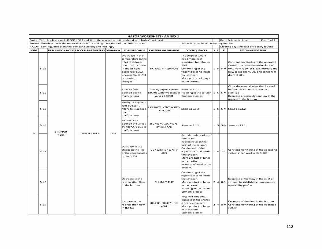
112
NODE DESCRIPTION NODE PROCESS PARAMETERS DEVIATION POSSIBLE CAUSE EXISTING SAFEGUARDS CONSEQUENCES S F R RECOMMENDATION
5.1.1
Drecrease in the
temperature in the
inlet of stripper
due to an increase
in the ∆T heat
exchanger E 202
because the D-203
presented
changes.
TIC 4017; TI 4139; 4063
The stripper would
need more heat
sumistred for reboiler
E203.
Condensing of the
vapor to ascend inside
the stripper.
More procuct of lungs
in the bottom.
1 5 5-M
Constant monitoring of the operated
system. Increase the recirculation
flow from reboiler E-203. Increase the
flow to reboiler E-203 and condenser
drum D-203.
5.1.2
PV 4051 fails
opened due to
malfunctions
TI 4135; bypass system
LBCF01 with two manual
valves GBCF01
Same as 5.1.1
Flooding in the column
Economic losses
1 5 5-M
Close the manual valve that located
before GBCF01 until process is
stabilize
Decrease of recirculation flow in the
top and in the bottom.
5.1.3
The bypass system
fails due to TV
4017B fails opened
due to
malfunctions
ZSO 4017B; VENT SYSTEM
XY 4017BSame as 5.1.2 1 5 5-M Same as 5.1.2
5.1.4
TIC 4017 fails
opened the valves
TV 4017 A/B due to
malfunctions
ZSC 4017A; ZSO 4017B;
XY 4017 A/BSame as 5.1.2 1 5 5-M Same as 5.1.2
5.1.5
Decrease in the
steam on the line
of the condensates
drum D-203
LIC 4128; FIC 4127; FV
4127
Partial condensation of
the steam
hydrocarburs in the
inlet of the column.
Condensed of the
vapor to ascend inside
the stripper.
More product of lungs
in the bottom.
Increase of level in the
bottom.
1 4 4-LConstant monitoring of the operating
systems than work with D-203
5.1.6
Decrease in the
recirculation flow
in the bottom
PI 4116; TI4117
Condensing of the
vapor to ascend inside
the stripper.
More product of lungs
in the bottom.
Flooding in the column
Economic losses
2 4 8-M
Decrease of the flow in the inlet of
stripper to stablish the temperature
operability profile
5.1.7
Increase in the
recirculation flow
in the top
LIC 4083; FIC 4073; PDI
4064
Potencial flooding.
Increase in the charge
o heat exchanger.
More product of lungs
in th bottom.
Economic losses.
2 4 8-M
Decrease of the flow in the bottom
Constant monitoring of the operated
system
LESS5STRIPPER
T-201
HAZOP WORKSHEET - ANNEX 1 Project Title: Application of HAZOP, LOPA and SIL to the alkylation unit catalyzed with hydrofluoric acid
Study Section: Selective Hydrogenation Process: The objective is the removal of diolefins and light fractions of the olefins stream
HAZOP Team: Figueroa Stefanny, Lombana Stefany and Ruiz Ingry Meeting days: All days of Febrary to June
TEMPERATURE
Date: Febrary to June Page 1 of 1

113
NODE DESCRIPTION NODE PROCESS PARAMETERS DEVIATION POSSIBLE CAUSE EXISTING SAFEGUARDS CONSEQUENCES S F R RECOMMENDATION
5.1.8
Presence of water in
the olefins stream
outside of the D-202
LIC 4078; LIC 4083; FIC
4073
Decrease in the propane
concentration. Presence of
lungs in the bottom. Cavitation
in the P -203 A/B pumps.
1 5 5-M
Increase of the steam flow in the bottom
from reboiler E-203.
Decrease of the flow in the inlet
stripper.
5.1.9
Tamponade in the
outside stream of the
reboiler E-203
TI 4115; PDI 4164
Same as 5.1.6. Overpressure in
the line pipe. Flooded in the
exchanger generating a high
level in the condensed drum D-
203 with partial condensation of
the vapor. Possible fire
explosion due a overpressure
generating a risk to the
employees, enviroment and
equipment.
5 2 10-M
Install a alarm indicator worked with TI
4115 due to the process required more
control in this part
Constat monitoring to ensure proper
operation of the process
5.1.10
Rupture in the outside
stream of the reboiler E-
203
TI 4115; PDI 4164
Sane as 5.1.6
Flooded in the exchanger
generating a high level in the
condensed drum D-203 with
partial condensation of the
vapor. Possible fire explosion
due a overpressure generating a
risk to the employees,
enviroment and equipment.
Air pollution
5 2 10-M Same as 5.1.9
5.1.11
Decrease in the olefins
inlet stream of the heat
exchanger E-203
PV 4051: TI 4063
Same as 5.1.6
Presence of vapor in the heat
exchanger otside to condensate
drum.
1 2 2-L Same 5.1.7
5.2.1
Increase in the
temperature in the
inlet of stripper due to
an decrease in the ∆T of
the heat exchanger E
202 because the D-203
presented changes.
TIC 4017; TI 4139; 4063
The stripper would need less
heat from reboiler E-203
Presence of hydrocarbon
vaporised in the top of the
issostroppier. Hydrogen
contamination. Decrease in the
propane concentration.
Economic losses
1 5 5-L
Constant monitoring of the operated
system.
Decrease the recirculation flow from
reboiler E-203.
Decrease the flow to reboiler E-203 and
condenser drum D-203.
5.2.2TIC 4017 fails closed the
valves TV 4017 A/B
ZSC 4017A; ZSO 4017B;
XY 4017 A/B
Same as 5.2.1
Overpressure in the pipe line.
Flooded in the exchanger E-202.
Possible fire explosion
generating a risk to the
employees, enviroment and
equipment.
5 2 10-M
Constant monitoring of the operated
system.
Decrease the recirculation flow from
reboiler E-203.
Increase in the flow of the top.
5.2.3
PV 4051 fails closed
interrupting the olefins
flow
Bypass System (LBCF01)
Manual valves GBCF01
before and after at
pressure valve
The stripper would need less
heat from reboiler E-203.
Presence of hydrocarbon
vaporised in the top of the
issostroppier. Hydrogen
contamination. Decrease in the
propane concentration.
Economic losses. Overpressure
in the line pipe. Possible
rupture of the pipe line due the
overpressure causing a posible
fire explosion generating risk
for the employees, enviroment
and equipment.
5 3 15-S
Constant monitoring of the operated
system.
Decrease the recirculation flow from
reboiler E-203.
Increase in the flow of the top.
HIGH
5STRIPPER
T-201
HAZOP WORKSHEET - ANNEX 1 Project Title: Application of HAZOP, LOPA and SIL to the alkylation unit catalyzed with hydrofluoric acid
Study Section: Selective Hydrogenation Process: The objective is the removal of diolefins and light fractions of the olefins stream
HAZOP Team: Figueroa Stefanny, Lombana Stefany and Ruiz Ingry Meeting days: All days of Febrary to June
LESS
TEMPERATURE
Date: Febrary to June Page 1 of 1

114
NODE DESCRIPTION NODE PROCESS PARAMETERS DEVIATION POSSIBLE CAUSE EXISTING SAFEGUARDS CONSEQUENCES S F R RECOMMENDATION
5.2.4
The bypass system fails
due to TV 4017B fails
closed
ZSO 4017B; VENT SYSTEM
XY 4017B
Same as 5.2.1
Overpressure in the line.
Interruptiom of flow after the
valve.
2 1 2-L
Inccrease the flow in the line of heat
exchanger E-202.
Increase the olefins steam in the
bottoms of stroppier.
5.2.5
Increase in the
temperature of olefins
inlent steam in the
bottoms.
TI 4115; PDY 4064; LIC
4069; TI 4070
Presence of hydrocarbon
vaporised in the top of the
issostroppier.
Economic losses
2 2 4-L
Decrease of the flow in the inlet of
stroppier.
Increase the recirculation flow in the
top.
5.2.6
Decrease in the
recirculation flow in the
top.
FIC 4073
Increase of vapor in the top.
Decrease in the quality
separation and charge of
olefins.
3 4 12-S
Decrease in the recirulation flow in the
bottoms.
Increase in the flow of charge to
stroppier.
5.2.7Decrease in the olefins
charge of stripperPV 4051 Same as 5.2.1 2 4 8-M
Decrease in the recirculation flow in the
bottoms.
Increase in the recirculation flow in the
top.
5.2.8
Increase in the steam
on the line of the
condensates drum D-
203
LIC 4128; FIC 4127; FV
4127
Presence of hydrocarbon
vaporised on the top of the
stroppier.
Economic losses.
2 2 4
Increase of the flow of charge to
stroppier.
Decresse in the recirculation flow of the
top.
5.3.1Increase in the charge
flow PV 4051; TI 4063
Flooding in the column.
Presence of lungs in the bottom.
Decreasse in the quality of
olefins. Hydrogen
contamination. Economic losses
2 3 6-M
Increase the outside flow to reboiler.
Increase de steam flow in the condenser.
Decrease the recriculation flow in the
top.
5.3.2
Decrease in the
recirculation flow in the
bottoms
TI 4115; TI 4070; LIC 4069 Same as 5.3.1 3 4 12-SDecrease the charge flow until flow is
stabilize
5.3.3
The tea system fails
opened due to
malfunctions
PI 4064; PI 4065; PSV
4066
Losses of hydrogen.
Air pollution 3 2 6-M
Decrease the charge flow.
Decrease the recirculation flow in the
botoms.
Open the security valves.
5.3.4
Increase in the
recirculation flow in the
top
LIC 4083; FIC 4073; PDI
4064
Potencial flooding.
Increase in the charge o heat
exchanger. More product
of lungs in th bottom.
Economic losses.
2 3 6-MIncrease in the recirculation flow in the
bottoms
5.3.5
Presence of water in
the hydrocarbon reflux
stream in the top
LI 4078; LIC 4083; FIC
4073; PDI 4064
Same as 5.3.1
The stripper would need more
heat from reboiler E-203
2 2 4-L Same as 5.3.4
PRESSURE
TEMPERATURE
STRIPPER
T-2015
HIGH
LESS
HAZOP WORKSHEET - ANNEX 1 Project Title: Application of HAZOP, LOPA and SIL to the alkylation unit catalyzed with hydrofluoric acid
Study Section: Selective Hydrogenation Process: The objective is the removal of diolefins and light fractions of the olefins stream
HAZOP Team: Figueroa Stefanny, Lombana Stefany and Ruiz Ingry Meeting days: All days of Febrary to June
Date: Febrary to June Page 1 of 1

115
NODE DESCRIPTION NODE PROCESS PARAMETERS DEVIATION POSSIBLE CAUSE EXISTING SAFEGUARDS CONSEQUENCES S F R RECOMMENDATION
5.4.1Decrease in the charge
flowPV 4051: TI 4063
Presence of hydrocarbon in the
top of the column.
Hydrogen contamination.
Decrease in the olefins quality.
Economic losses
2 3 6-M
Decrease of the recirculation flow in the
bottoms.
Increase of the recirculation flow in the
top.
5.4.2
Increase in the
recirculation flow in the
bottoms
PI 4064; PI 4065; PSV
4066Same as 3.4.1 2 3 6-M
Decrease of the recirculation flow in the
top.
Decrease the charge flow
5.4.3
Decrease in the
recirculation flow in the
top
LIC 4083; FIC 4073; PDI
4064
Same as 3.4.1
Increase of steam in the top2 3 6-M Same as 5.3.4
5.4.4The tea system fails
clossed
PI 4064; PI 4065; PSV
4066
Possible floofing into the
stripper.
Overpressure.
Losses of olefins.
4 2 8-MOpen the safe valve GBCF01 and GACF04
to stabilize the pressure in the tower
5.4.5
Tamponade in the
outside stream in the
bottoms
LIC 4069; TI 4079
Increase the olefinsin the
bottoms.
Overpressure into stripper.
Potencial flooding.
Hydrogen contamination.
Economic losses.
5 1 5-M
Decrease the charge flow.
Decrease the recirculation flow in the
top.
Decrease the steam flow in the
condenser D 203
5.5.1
Tamponade in the
charge line of the
stripper
PV 5051; TI 4063; LBCF01;
LIC 4069
Same as 5.5.1
Overpressure in the pipe line
Possible fire explosion with
possible risk to employees,
enviroment and equipment
5 2 10-M
Same as 5.4.1
Constant monitoring to the system
controls
5.5.2 PV 4051 fails closed LBCF01; TI 4063; LIC 4069 Same as 5.5.3 5 1 5-M Same as 5.5.3
5.5.3Rupture in the outside
line in the bottom
TI 4070; GWC01 - PP; LIC
4069
Same as 5.5.2
Economic losses
Escape of lighs
5 2 10-M Same as 5.4.5
5.5.4
Tamponade in the
recirculation line of the
top
FIC 4073; PDI 4064Same as 5.5.3
Same as 5.5.65 1 5-M
Same as 5.2.6
Monitoring constant to the control
systems
LEVEL
PRESSURE HIGH
LESS
HAZOP WORKSHEET - ANNEX 1 Project Title: Application of HAZOP, LOPA and SIL to the alkylation unit catalyzed with hydrofluoric acid
Study Section: Selective Hydrogenation Process: The objective is the removal of diolefins and light fractions of the olefins stream
HAZOP Team: Figueroa Stefanny, Lombana Stefany and Ruiz Ingry Meeting days: All days of Febrary to June
STRIPPER
T-2015
Date: Febrary to June Page 1 of 1

116
NODE DESCRIPTION NODE PROCESS PARAMETERS DEVIATION POSSIBLE CAUSE EXISTING SAFEGUARDS CONSEQUENCES S F R RECOMMENDATION
5.6.1 PV 4051 fails opened LBCF01; TI 4063; LIC 4069Same as 5.4.1
Flooding in the column 4 1 4-L
Open the safe valve LBCF01 to stabilize
the operability profile
5.6.2TV 4017 A/B fails
openedTI 4139; TI 4063; PV 4051 Same as 5.6.1 4 1 4-L Same as 5.3.1
5.6.3 FIC 4073 fails closed LWCS01; SP 0182
Overpressure in the D-201
Posible rupture of the pipe line
due to overpressute
4 1 4-LOpen the safe valve LWCS01 to stabilize
the operability profile
5.6.4
Tamponade in the
outside line in the
bottom
TI 4070; TW4179Same as 5.4.5
Decreasse in the olefins quality5 2 10-M Same as 5.4.3
5.6.5LIC 4069 fails closed fv
4061Same as 5.6.1
Same as 5.6.1
Same as 5.6.4
Increase the charge for the
reboiler E 203
5 1 5-MOpen the safe valve LBCF01 to stabilize
the operability profile
5.7.1
The feed stream of the
process comes with
some diolefins
PDY 4064; LIC 4069; TI
4115
Decrease in the temperature
profile.
Decrease in the molecular
weight on the plates along of
towel.
Decrease in the olefins quality
2 2 4-L Same as 4.9.1
5.7.2
The feed stream of the
process comes with less
diolefins and olefins
concentration and more
contaminant such as
sulfur, heavy metals,
water and caustic soda.
Same as 5.7.1
Same as 5.7.1
Contamination of the finale
product
2 3 6-M
Constant monitoring and Periodic
maintenance to pipeline and
equipments to ensure proper operation
of the process
5.8.1 HIGH
Increase in the
molecular weight of the
charge
Same as 5.7.1
Decresse in the sensible heat.
Decrease in the molecular wight
in the products of top and
bottom
3 2 6-M
Constant monitoring to the variables like
pressure, flow and temeprature to
prevent chances in the composition
LEVEL
STRIPPER
T-2015
HIGH
LESS
CHARGE
COMPOSITION
HAZOP WORKSHEET - ANNEX 1 Project Title: Application of HAZOP, LOPA and SIL to the alkylation unit catalyzed with hydrofluoric acid
Study Section: Selective Hydrogenation Process: The objective is the removal of diolefins and light fractions of the olefins stream
HAZOP Team: Figueroa Stefanny, Lombana Stefany and Ruiz Ingry Meeting days: All days of Febrary to June
Date: Febrary to June Page 1 of 1

117
Annex 2 Application of HAZOP methodology to Charge and Drying section
NODE DESCRIPTION NODE PROCESS PARAMETERS DEVIATION POSSIBLE CAUSE EXISTING SAFEGUARDS CONSEQUENCES S L R RECOMMENDATION
1.1.1
Temperature of inlet is
cooler than normal
(<110°F)
TI 4062; TI/TE 1001, TI 2495
Increase in the separation
time between hydrocarbon
and water.
1 1 1-L
Install an Temperature Indicator in the
inlet line to surge drum D-02 to
monitoring this operational variable in
the control room
1.1.2Decrease in the pressure
tank (<75 psig)PI 1364 Same as 1.1.1 1 3 3-L
Realize constant operator procedures,
monitoring and training. Do a schedule
to realice the activities in this section.
1.2.1
Temperature of inlet is
higher than normal
(>110°F)
Same as 1.1.1
Decrease in the separation
time between hydrocarbon
and water
1 4 4-L Same as 1.1.1
1.2.2
Increase in the pressure
tank due to generation
vapor (>75psig)
Same as 1.1.2; PSV 1002
Same as 1.2.1
Increase in the NPSH
causing mechanical
damage in the pump P-
01A/B. Overpressure in the
drum D-02
2 2 4-L Same as 1.1.2
1.3.1Manual valve GWCS03 is
opened PDI 1003; PI 1364/1021
Hydrocarbon spill to
atmosphere causing air
pollution and potential
fire. Risk to the employees
and the equipments.
Economic losses.
5 2 10-M
Realize periodic maintenance and
monitoring to the surge drum and
manual valves inmediatly report about
the real state of the tank. Do a schedule
to realice that action.
1.3.2 The PSV 1002 fails opened GACF04, PDI 1003, PI1364
Hydrocarbon spill to
atmosphere causing air
pollution and potential
fire. Risk to the employees
and the equipments.
Economic losses. Decrease
in the NPSH causing
cavitation in the pump P-
01A/B
4 2 8-M
Realize a periodic maintance to the
valve PSV 1002 to avoid this kind of
causes in the unit and is convenient do a
schedule to realice this type of actions
1.3.3 Manual Valve GBCF18 is
opened PI 2450, PDI 1003 Same as 1.3.2 4 2 8-M Same as 1.3.1
1.4.1
Increase in the
temperature inside the D-
02
Same as 1.1.1. PSV 1002; PI
1364, TEA system
The outlet stream is
contaminated with vapor
of water. Potential fire and
explosion in the drum
2 2 4-L
The surge drum count with the
necessary safeguards, realize constant
monitoring of pressures and
temperature indicator.
1.4.2The PSV 1002 fails closed or
malfunctions
Bypass system around PSV
1002; PI 1364,
Overpressure in the drum
D-02. Potential explosion
of the drum
3 2 6-M Same as 1.3.2
SURGE DRUM D-021
HAZOP WORKSHEET - ANNEX 2 Project Title: Application of HAZOP, LOPA and SIL to the alkylation unit catalyzed with hydrofluoric acid
Process: The objective is to remove humidity of the charge currents the unit Study Section: Charge and Drying
HAZOP Team: Figueroa Stefanny, Lombana Stefany and Ruiz Ingry Meeting days: All days of Febrary to June
Date: Febrary to June Page 1 of 1
TEMPERATURE
LESS
HIGH
PRESSURE
HIGH
LESS

118
NODE DESCRIPTION NODE PROCESS PARAMETERS DEVIATION POSSIBLE CAUSE EXISTING SAFEGUARDS CONSEQUENCES S L R RECOMMENDATION
1.5.1FV 1000 fails closed or
malfunctions
LI 1005 with low level and
low-low alarm; Bypass
around FV 1000 valve with
manual valve LWCS03
If this valve fails more than
30 minutes is potential to
shutdown the Alkylation
unit or go on isubutane
circulation. Economic
losses due to loss of
production.
3 3 9-M
Consider adding a low flow alarm on FIC
1000 and realice operator procedures,
trainig and response
1.5.2
The FIC 4061 and/or LIC
4069 fails closing the valve
FV 4061
Same as 1.5.1.
Same as 1.5.1. Increase the
level in the bottom of
stripper T-201 causing
overpressure and potential
explosion of the vessel.
4 2 8-M
Intall a Flow Indicator in the inlet line of
the Surge Drum to monitoring the inlet
flow to the drum. Periodic maintenance
to the existing safeguards and valves.
Realize operator procedures and
training
1.5.3XV 2453 fails closed or
malfunctions
LI 1005 with low level and
low-low alarm; Position
indication (ZIC 2453) on XV
2453
Same as 1.5.1 3 2 6-M
Realize monitoring and constant
maintenance to the valve XV 2453 and
operator procedures, training and
response.
1.5.4 FV 1006 fails closed or
malfunctions
Same as 1.5.1; FE 1006,
FT/FIC 1006 Same as 1.5.1 3 3 9-M Same as 1.5.2
1.5.5LV 1004 fails opened or
malfunctions
PI 1364, LIC/LT 1004, LG
1009 for operator to verify
level in boot, LI 1005 with
low level and low-low
alarm, Bypass around LV
1004
Same as 1.5.1
Potential to send
isobutane/olefin feed to
the neutralizer drum D-19.
Potential loss of feed.
Economic losses
3 3 9-M
Intall a Flow Indicator in the drain line of
oily water. Do periodic monitoring to
the state of the plant.
1.5.6Rupture or leak in the
principle inlet line to D-02
Manuals valves CBCF01/
LWCS03/ LBCF06 to close
the inlet flow for each
streams; XV 2453; FV1006
Potential fire and
explosion.Hydrocarbon
spill to atmosphere causing
air pollution. Risk to the
employees and the
equipments. Economic
losses. Decrease in the
NPSH causing cavitation in
the pump P-01A/B.
Decrease in the pressure
tank
4 3 12-S
Install a Flow Indicator in the inlet line
of surge drum and flow indicator with
lower and higher Alarm in the drum.
Constantly check of the pipe and realize
maintenance to the pipes and vessels
and training to the operator if this cause
occurs.
1.5.7XV 1516 fails opened or
malfunctions
Position valve indication
on XV 1516; FIC
1059C/1903C with low flow
alarm on E-28/E28A reactor
feed lines; PSV 1002 on D-
02 set at 170 psig, design
pressure of vessel is higher
than maximum expected,
LI 1005 with high level and
low - low alarm
Same as 1.5.1 2 3 6-M
Periodic maintenance to the XV 1516
and realice operator procedures,
training and response. Consider install a
PT/PI with high pressure alarm on surge
drum D-02
1.5.8Rupture in the outlet lines
of the drum D-02
LI 1005 with low level and
low-low alarm, Manual
valve GWCS03, XV 1516
Same as 1.5.6 4 3 12-S
Install a Flow Indicator in the outlet line
of the surge drum. Realize operator
procedures and training
1.5.9Rupture or break in the oily
water drain line Same as 1.5.8
Same as 1.5.6
Hydrocarbon load loss 5 2 10-M Same as1.5.5
1.5.10Tamponade in the inlet
pipes
LI 1005 with low level and
low-low alarm
Rupture in the inlet line
due to overpressure in it
causing possible potential
fire. Decrease in the NPSH
causing cavitation in the
pump P-01A/B
Decrease in the pressure
tank
5 2 10-M Same as 1.5.6
1.5.11
Loss of inlet flow from
stripper bottoms trim
cooler, butamer unit, D-01,
D-12, P-07A/B, P-06A/B, E-
06A/B
LI 1005 with low level and
low-low alarm
Potential to shutdown
alkylation unit or go on
isobutane circulation.
Economic losses due to
loss of production
3 3 9-M
Consider adding a low flow alarm on FIC
1000 and realice operator procedures,
training and response
1 SURGE DRUM D-02 LEVEL
HAZOP WORKSHEET - ANNEX 2 Project Title: Application of HAZOP, LOPA and SIL to the alkylation unit catalyzed with hydrofluoric acid
Process: The objective is to remove humidity of the charge currents the unit Study Section: Charge and Drying
HAZOP Team: Figueroa Stefanny, Lombana Stefany and Ruiz Ingry Meeting days: All days of Febrary to June
Date: Febrary to June Page 1 of 1
LESS
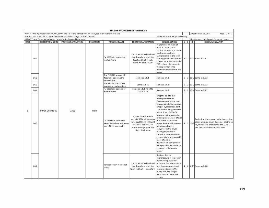
119
NODE DESCRIPTION NODE PROCESS PARAMETERS DEVIATION POSSIBLE CAUSE EXISTING SAFEGUARDS CONSEQUENCES S L R RECOMMENDATION
1.6.1FV 1000 fails opened or
malfunctions
LI 1005 with low level and
low-low alarm and high
level and high - high
alarm, XV2453; PI 1364
Higher consumption of
Acid in the reaction
section. Drag of acid to the
Isostripper section.
Overpressure in the tank
causing possible explosion.
Drag of hydrocarbon to the
TEA system Decrease in
the separation time
between hydrocarbon and
water
5 2 10-M Same as 1.5.1
1.6.2
The FIC 4061 and/or LIC
4069 fails opening the
valve FV 4061
Same as 1.5.1 Same as 1.6.1 5 2 10-M Same as 1.5.2
1.6.3The valve XV 2453 fails
opened or malfunctions Same as 1.5.3 Same as 1.6.1 5 2 10-M Same as 1.5.3
1.6.4FV 1006 fails opened or
malfunctions
Same as 1.5.1; FE 1006,
FT/FIC 1006 Same as 1.6.1 5 2 10-M Same as 1.5.2
1.6.5
LV 1004 fails closed for
example bad transmitter or
loss of instrument air
Bypass system around
valve LV 1004 with manual
valve LWCS03; LI 1005 with
low level and low-low
alarm and high level and
high - high alarm
Drag the acid to the
Isostripper section
Overpressure in the tank
causing possible explosion.
Drag of hydrocarbon to the
TEA system. Drag of water
to the dryers D-03A/B.
Increase in the corrosion
of equipments. Loss of acid
due to the increase of
water. Potential for water
buildup and water
carryover to the dryer
leading to potential
corrosion in downstream
system. Overtime, possible
leaks of acid in
downstream equipments
with possible exposure to
employees. Economic
losses
4 3 12-S
Periodic maintenance to the bypass line,
pipes an surge drum. Consider adding an
HF/Water acid analyzer on the E-28/E-
28A reactor acid circulation loop
1.6.6Tamponade in the outlet
pipes
LI 1005 with low level and
low-low alarm and high
level and high - high alarm
Rupture due to
overpressure in the outlet
pipe causing possible
potential fire. The NPSH is
less than requested and
cause cavitation in the
pump P-01A/B Drag of
hydrocarbon to the TEA
system
4 2 8-M Same as 1.5.8
HIGH LEVELSURGE DRUM D-021
HAZOP WORKSHEET - ANNEX 2 Project Title: Application of HAZOP, LOPA and SIL to the alkylation unit catalyzed with hydrofluoric acid
Process: The objective is to remove humidity of the charge currents the unit Study Section: Charge and Drying
HAZOP Team: Figueroa Stefanny, Lombana Stefany and Ruiz Ingry Meeting days: All days of Febrary to June
Date: Febrary to June Page 1 of 1
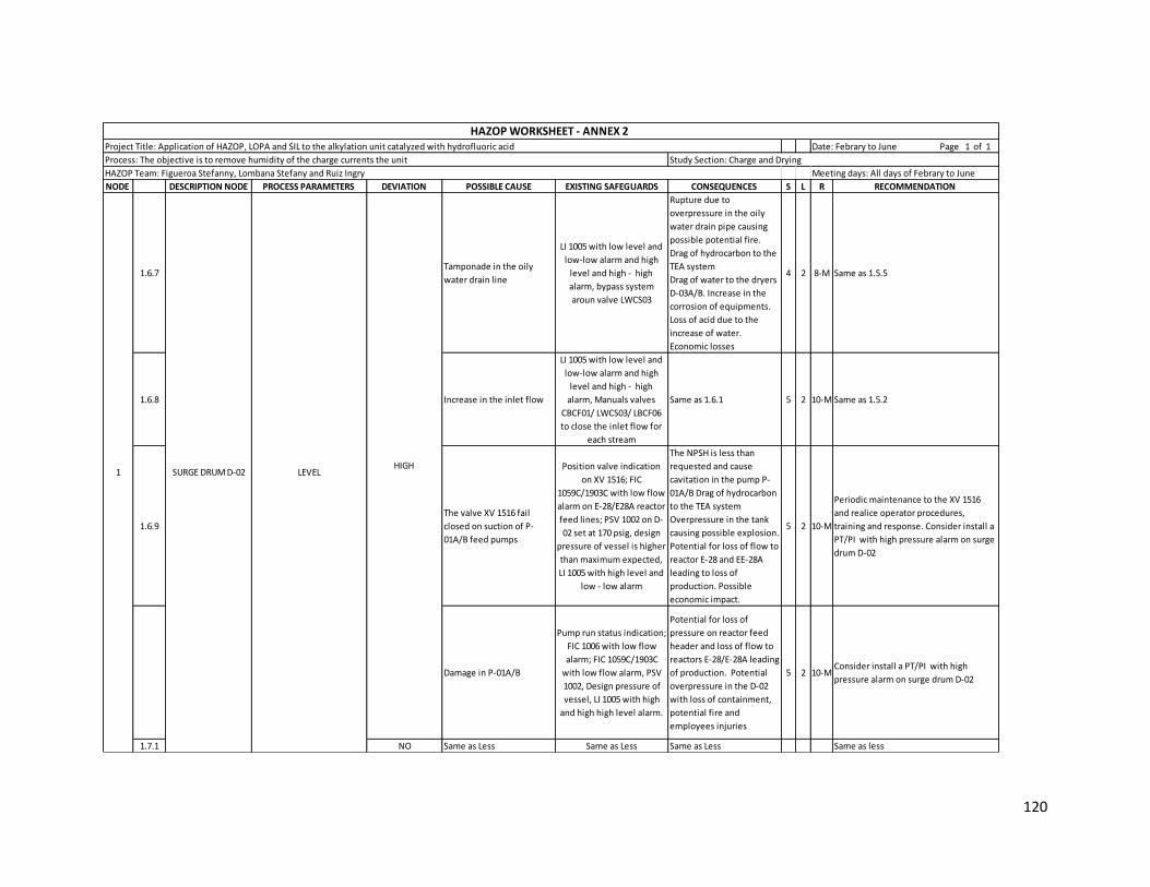
120
NODE DESCRIPTION NODE PROCESS PARAMETERS DEVIATION POSSIBLE CAUSE EXISTING SAFEGUARDS CONSEQUENCES S L R RECOMMENDATION
1.6.7Tamponade in the oily
water drain line
LI 1005 with low level and
low-low alarm and high
level and high - high
alarm, bypass system
aroun valve LWCS03
Rupture due to
overpressure in the oily
water drain pipe causing
possible potential fire.
Drag of hydrocarbon to the
TEA system
Drag of water to the dryers
D-03A/B. Increase in the
corrosion of equipments.
Loss of acid due to the
increase of water.
Economic losses
4 2 8-M Same as 1.5.5
1.6.8 Increase in the inlet flow
LI 1005 with low level and
low-low alarm and high
level and high - high
alarm, Manuals valves
CBCF01/ LWCS03/ LBCF06
to close the inlet flow for
each stream
Same as 1.6.1 5 2 10-M Same as 1.5.2
1.6.9
The valve XV 1516 fail
closed on suction of P-
01A/B feed pumps
Position valve indication
on XV 1516; FIC
1059C/1903C with low flow
alarm on E-28/E28A reactor
feed lines; PSV 1002 on D-
02 set at 170 psig, design
pressure of vessel is higher
than maximum expected,
LI 1005 with high level and
low - low alarm
The NPSH is less than
requested and cause
cavitation in the pump P-
01A/B Drag of hydrocarbon
to the TEA system
Overpressure in the tank
causing possible explosion.
Potential for loss of flow to
reactor E-28 and EE-28A
leading to loss of
production. Possible
economic impact.
5 2 10-M
Periodic maintenance to the XV 1516
and realice operator procedures,
training and response. Consider install a
PT/PI with high pressure alarm on surge
drum D-02
Damage in P-01A/B
Pump run status indication;
FIC 1006 with low flow
alarm; FIC 1059C/1903C
with low flow alarm, PSV
1002, Design pressure of
vessel, LI 1005 with high
and high high level alarm.
Potential for loss of
pressure on reactor feed
header and loss of flow to
reactors E-28/E-28A leading
of production. Potential
overpressure in the D-02
with loss of containment,
potential fire and
employees injuries
5 2 10-MConsider install a PT/PI with high
pressure alarm on surge drum D-02
1.7.1 NO Same as Less Same as Less Same as Less Same as less
SURGE DRUM D-021 LEVELHIGH
HAZOP WORKSHEET - ANNEX 2 Project Title: Application of HAZOP, LOPA and SIL to the alkylation unit catalyzed with hydrofluoric acid
Process: The objective is to remove humidity of the charge currents the unit Study Section: Charge and Drying
HAZOP Team: Figueroa Stefanny, Lombana Stefany and Ruiz Ingry Meeting days: All days of Febrary to June
Date: Febrary to June Page 1 of 1

121
NODE DESCRIPTION NODE PROCESS PARAMETERS DEVIATION POSSIBLE CAUSE EXISTING SAFEGUARDS CONSEQUENCES S L R RECOMMENDATION
2.1.1 LESS
Inlet temperature is lower
than operating
temperature (<102°F)
TI 1025/1026 No significant consequences 1 1 1-L
The inlet line has enough safeguards but
is necessary realize periodic
maintenance to the indicators.
2.2.1
Inlet temperature is higher
than operating
temperature (>102°F)
Same as 2.1.1
Decrease in the efficiency
of removal water from
olefins.
Increase in the moisture
into dryers causing
saturation in the molecular
sieves and decrease the
drying cycle operation
2 2 4-L Same as 2.1.1
2.2.2Increase the friction in the
inlet pipe Same as 2.1.1 Same as 2.2.1 2 2 4-L
Realice periodic maintenance to the
pipes and operator procedures and
training.
2.2.3 Increase in the pressure PSV 1027/1028 Same as 2.2.1 2 1 2-LSame as 2.2.2. Intall a pressure indicator
in each dryer.
2.3.1
XV 1350/1351 fails closed
or malfunctions decreasing
the inlet flowto olefins
feed driers D-03A/B
XV 1352, XV 1353
Increase in the lifetime of
molecular sieves due to
decrease in the moisture
into dryers but decrease
the charge to the reaction
step.
Possible fire explosion and
leak of hydrocarbon due to
overpressure in the inlet
pipe.
Economic losses
3 3 9-MSame as 2.2.2. Install a flow indicator
after valve 1350/1351
2.3.2PSV 1027/1028 fails opened
or malfunctions
GACF 04, Bypass system
around valves PSV
1027/1028
Air pollution due to
hydrocaron escape. Injures
to employees and
equipment. Economic
losses.
2 3 6-M Same as 2.2.2
2.3.3
XV 1352/1353 fails opened
depending of what dryer is
using
Drain line with manual
valve GWCS03
Decrease in the level due
to reverse flow of olefins
which are sending to the
coalescer
1 2 2-L Same as 2.3.3
2.4.1Increase in the charge to
the dryer XV 1350/1351 Same as 2.2.1 2 2 4-L
Install a flow indicator control (FIC)
which works with a control valve in the
inlet stream to monitoring the flow in
the dryer.
2.4.2Tamponade in the outlet
pipe. PI 2548
Possible fire explosion and
leak of hydrocarbon due to
overpressure in the outlet
pipe.
Decrease in the charge to
the reaction step.
5 2 10-M Same as 2.2.2
2.4.3 PSV 1027/1028 fails closed Bypass with valve LBCF06
Posible explosion due to
overpressure into the tank
.
4 2 8-M Same as 2.3.3
2.4.4
Increase in the inlet
temperature to olefins
feed driers
TT/T1025, TT/TI1026 Same as 2.2.1 2 2 4-L Install a PDI in each olefins feed driers
PRESSURE
2OLEFIN FEED DRIERS
IN USE D-03A/B
TEMPERATURE
HIGH
LESS
HIGH
HAZOP WORKSHEET - ANNEX 2 Project Title: Application of HAZOP, LOPA and SIL to the alkylation unit catalyzed with hydrofluoric acid
Process: The objective is to remove humidity of the charge currents the unit Study Section: Charge and Drying
HAZOP Team: Figueroa Stefanny, Lombana Stefany and Ruiz Ingry Meeting days: All days of Febrary to June
Date: Febrary to June Page 1 of 1

122
NODE DESCRIPTION NODE PROCESS PARAMETERS DEVIATION POSSIBLE CAUSE EXISTING SAFEGUARDS CONSEQUENCES S L R RECOMMENDATION
2.5.1 LESS Good separation in the
charge drum D-02 No safeguards
Increase in the lifetime of
molecular sieves due to
decrease in the moisture
into dryer.
Increase in the drying cycle
operation.
2 3 6-M
Install a analyzer in the inlet pipe and
realice sampling procedures in the
stream.Periodic operator procedures
and training.
2.6.1
LIC 1004 fails closing the
valve LV 1004 causing
water drag in the olefins
stream.
Same as 1.6.5 Same as 2.2.1 2 2 4-L Same as 1.6.5
2.6.2
Bad separation in the
charge drum D-02 due to
high temperature
Same as 1.2.2 Same as 2.2.1 2 2 4-L Same as 1.1.1
2.7.1Molecular sieves recently
regenerated AI 1030
No hydrate formation in
the reaction 2 1 2-L No important comments to do
2.7.2Decrease in the moisture
of the inlet stream Same as 2.7.1
Increase in the lifetime of
molecular sieves.
Same as 2.7.1
1 1 1-L
Install a analyzer in the inlet pipe and
realice sampling procedures in the
stream.Periodic operator procedures
and training.
2.7.3Decrease in the sieves
operation time No safeguards Same as 2.7.2 1 2 2-L No important comments to do
2.8.1Increase in the sieves
operation time No safeguards 2 1 2-L No important comments to do
2.8.2Saturation of molecular
sieves Same as 2.7.1 2 2 4-L
Schedule the regeneration of the
molecular sieves.
2.8.3 Increase in the inlet flow Same as 2.4.1 2 1 2-L Same as 2.4.1
2.8.4Increase in the moisture in
the inlet stream No safeguards (drum) 2 3 6-M
Realize sampling procedures in the inlet
stream and periodic maintenance to the
pipes and drum
2.9.1 XV 1350/1351 fails closed No safeguards Same as 2.3.1 2 3 6-M Install a bypass system around the
valves XV 1350/1351
2.9.2Leak or rupture in the inlet
pipe No safeguards Same as 2.3.2 3 3 9-M
Install a flow indicator in the inlet pipe.
Periodic pipe maintenance
2.9.3Tamponade in the inlet
pipe.
Drain line with manual
valve GWCS03
Possible fire explosion and
leak of hydrocarbon due to
overpressure in the inlet
pipe.
4 2 8-MSame as 2.2.2. Install a pressure
indicator in the inlet pipe.
2.9.4
XV 1352/1353 fails opened
depending of what dryer is
using
No safeguards Same as 2.3.4 1 2 2-L
Install a manual valve after valves XV
1352/1353 and do periodic maintenance
to the valves, equipments and drum.
2.10.1 HIGH XV 1350/1351 fails opened No safeguards
Increase the moisture into
the dryers. Decrease the
lifetime of molecular
sieves.
2 2 4-L No important comments to do
2OLEFIN FEED DRIERS
IN USE D-03A/B
Decrease in the lifetime of
molecular sieves.
Increase in the operational
cost due to constant dryer
regeneration.
Hydrate formation in the
reaction step. Acid
losses.
WATER CONCENTRATION IN
THE INLET STREAM
HIGH
INLET FLOW
LESS
WATER CONCENTRATION IN
THE OUTLET STREAM
LESS
HIGH
HAZOP WORKSHEET - ANNEX 2 Project Title: Application of HAZOP, LOPA and SIL to the alkylation unit catalyzed with hydrofluoric acid
Process: The objective is to remove humidity of the charge currents the unit Study Section: Charge and Drying
HAZOP Team: Figueroa Stefanny, Lombana Stefany and Ruiz Ingry Meeting days: All days of Febrary to June
Date: Febrary to June Page 1 of 1

123
NODE DESCRIPTION NODE PROCESS PARAMETERS DEVIATION POSSIBLE CAUSE EXISTING SAFEGUARDS CONSEQUENCES S L R RECOMMENDATION
3.1.1
FV 1023 fails opened
increasing the inlet flow
olefins in the E-01
FT 1023, GWCS03
Decrease in the
regeneration efficiency to
the D-03A/B.
1 2 2-L
Realice periodic maintenance to the
valve FV 1023. Consider if it is possible
install a FI in the inlet line in the E-01 to
control of the inlet flow in the control
room
3.1.2TIC 1022 fails closing the
valve FV 1024
TI 1540, FIC 1024, Bypass
system with manual valve
LWCS 02
Same as 3.1.1 1 1 1-L
The line has enough safeguards but
realize constant monitoring to the
controllers, pipes and valves
3.1.3
FIC 1024 fails closing the
valve FV 1024 decreasing
the inlet flow of steam
TIC 1022; Bypass system
with manual valve LWCS 02Same as 3.1.1 1 2 2-L Same as 3.1.2
3.1.4Level in the condenser
increaseLIC 2455
Decrease the heat transfer
in the E-01.
Overpressure in the E-01.
Same as 3.1.1
2 2 4-L
Constant monitoring to the LIC 2455 and
valve LV 2455 and do an operator
procedures.
3.2.1
FV 1023 fails closed
decreasing the inlet flow
of olefins in the E-01
FT 1023; Bypass system
with manual valve LWCS02
Inefficient use of steam.
Possible increase in the
pressure of D-02 and D-
03A/B.
Increase in the
regeneration time due to
cooling time required for
it.
2 2 4-L Same as 3.1.1
3.2.2TIC 1022 fails opening the
valve FV 1024 TI 1540, FIC 1024,GDCF04.
Inefficient use of steam.
Difficulty in separating the
water from the olefins due
to increase the coalescer
temperature.
1 2 2-L Same as 3.1.2
3.2.3
FIC 1024 fails opening the
valve FV 1024 decreasing
the inlet flow of steam
TIC 1022; GDCF04 Same as 3.2.2 1 2 2-L Same as 3.1.2
3.3.1
XV 1346/1347 fails closed No safeguards Same as 3.1.1 1 4 4-L
Periodic maintenance to the valve XV
1346/1347. Install a flow indicator after
valves 1346/1347 to monitoring the flow
in the inlet stream. Install a bypass
system around valves 1346/1347.
3.3.2FV 1023/1024 fails closed or
malfunctions
Bypass in the inlet lines of
olefin regenerant heater E-
01 around valves FV
1023/1024 with manual
valve LWCS 03
Same as 3.1.1 1 1 1-L Same as 3.1.1
3.3.3Tamponade in the inlet
pipe of olefin driers
Drain line with manual
valve GBCF18Same as 3.1.1 1 4 4-L
Periodic maintenance to the pipes and
consider install a pressure indicator or
flow indicator in the inlet stream.
3.4.1
FV 1023 fails opened and
the regeneration steam go
out to the E-01 to the
operational temperature.
GWCS 03
Increases the rate of
removal of moisture
resulting in improved
regeneration cycle.
Increase regeneration
cycle time
1 4 4-L Same as 3.1.1
3.4.2XV 1346/1347 fails opened
or malfunctions No safeguards Same as 3.4.1 1 4 4-L Same as 3.3.1
OLEFIN FEED DRIERS
IN REGENERATION D-
03A/B
TEMPERATURE IN THE INLET
STEAM
LESS
HIGH
HAZOP WORKSHEET - ANNEX 2 Project Title: Application of HAZOP, LOPA and SIL to the alkylation unit catalyzed with hydrofluoric acid
Process: The objective is to remove humidity of the charge currents the unit Study Section: Charge and Drying
HAZOP Team: Figueroa Stefanny, Lombana Stefany and Ruiz Ingry Meeting days: All days of Febrary to June
Date: Febrary to June Page 1 of 1
FLOW IN THE INLET STREAM
LESS
HIGH
3

124
NODE DESCRIPTION NODE PROCESS PARAMETERS DEVIATION POSSIBLE CAUSE EXISTING SAFEGUARDS CONSEQUENCES S L R RECOMMENDATION
4.1.1
The temperature of inlet
stream is lower than
operating temperature.
Preheating in E-01, TI1549
with low temperature
alarm
Lower production of steam
in the condenser
More production of liquid
phase in the drum
(Increase in the out flow
rate) Decrease in the
pressure inside the
condenser
2 2 4-L
Install a temperature indicator to
monitoring this property in the control
room. Realize operator procedures
4.1.2
Increase of the ∆T due to
decrease in the inlet
temperature of olefins in
the heat exchanger E-01
TI1549 with low
temperature alarm Same as 4.1.1 2 2 4-L Same as 4.1.1
4.1.3
FV 1024 fails closed or
malfunctions on steam to E-
21
TI 1540 with low
temperature alarm,
Bypass around FV 1024
Loss of heat input to E-01.
Delay the regeneration
process.
1 1 1-L
Periodic maintenance and monitoring to
the valve FV 1024 and the control of it to
avoid that this control send a wrong
signal to the control room.
4.2.1
The temperature of inlet
stream is higher than
operating temperature.
TI1549 with low
temperature alarm
Increase in the pressure
causing more production of
steam
More production of steam
in the condenser and lower
production of liquid phase
1 2 2-L Same as 4.1.1
4.2.2
Decrease of the ∆T due to
increase in the inlet
temperature of diolefins
and olefins in the heat
exchanger E-01
TI1549 with low
temperature alarmSame as 4.2.1 2 2 4-L Same as 4.1.2
4.2.3FV 1024 fails opened or
malfunctions
TI 1540 with low
temperature alarm,
Bypass around FV 1024,
manual valve GDCF04
Economic losses due to
unnecesary use of steam.
Same as 4.2.1
1 2 2-L Same as 4.1.3
4.3.1 Decrease or NO steam flow PI 1357 No exist condesation 1 1 1-L
Install a flow indicator in the inlet steam
line and realize monitoring in the line
and the pressure indicator.
4.3.2Decrease in the inlet
stream flowNo safeguards
Drag of steam to head
condensate. Economic
losses
1 2 2-LInstall a Flow Indicator in the inlet of
the D-24
4.3.3Decrease in the inlet
stream temperature
Preheating in E-01, TI1549
with low temperature
alarm
Same as 4.1.1 2 3 6-M Same as 4.1.1
4.3.4 Break in the steam pipe No safeguards Risk to the employees and
the atmosphere 4 2 8-M
Same as 4.3.1. Do periodic maintenance
to the pipes and operator procedures in
the unit
4.3.6 PSV 2496 fails opened
Manual valve GWCS02
located before valve PSV
2496
Same as 4.3.4 2 3 6-MRealize monitoring and constant
maintenance to the valve PSV 2496.
4.3.7LV 2455 fails opened or
malfunctions
Manual valve GWCS02
located after valve LV 2455
Decrease the level in the
condenser Same as 4.3.23 3 9-M Same as 3.1.4
4.3.8Tamponade in the inlet
pipeNo safeguard
Rupture due to
overpressure in the inlet
pipe causing possible
injuries to employees
4 2 8-M
Same as 4.3.2. Periodic maintenance to
the pipes and consider install a pressure
indicator
PRESSURE
CONDENSER D-244
TEMPERATURE
LESS
HIGH
LESS
HAZOP WORKSHEET - ANNEX 2 Project Title: Application of HAZOP, LOPA and SIL to the alkylation unit catalyzed with hydrofluoric acid
Process: The objective is to remove humidity of the charge currents the unit Study Section: Charge and Drying
HAZOP Team: Figueroa Stefanny, Lombana Stefany and Ruiz Ingry Meeting days: All days of Febrary to June
Date: Febrary to June Page 1 of 1

125
NODE DESCRIPTION NODE PROCESS PARAMETERS DEVIATION POSSIBLE CAUSE EXISTING SAFEGUARDS CONSEQUENCES S L R RECOMMENDATION
4.4.1LV 2455 fails closed or
malfunctions
Bypass system around
valve LV 2455; PI 1357; PSV
2496, LIC 2455, LG 2454
Increase in the level
causing dawg of
condensate to the steam
line.
1 2 2-L Same as 3.1.4
4.4.2Increase in the inlet flow
stream No safeguard Same as 4.4.1 1 4 4-L Same as 4.3.2
4.4.3 PSV 2496 fails closed.
Drain line in the top of the
condenser, Design
procedures
Explosion in the condenser
due to overpressure inside
the vessel.
3 3 9-M Same as 4.3.6
4.4.4Increase in the inlet stream
temperaturePI 4104 ; PSV 2496
More production of steam
in the condenser and lower
production of liquid phase
1 3 3-L Same as 4.1.1. Same as 4.1.2
4.4.5Tamponade in the outlet
pipeLIC 2455; PI 1357, LG 2454
Same as 4.4.1
Rupture due to
overpressure in the outlet
pipe causing possible
injuries to employees
3 3 9-M Periodic maintenance to the pipes and
operator procedures and training
4.5.1LV 2455 fails opened or
malfunctions
Manual valve GWCS02
located after valve LV 2455Same as 4.3.2 2 2 4-L Same as 3.1.4
4.5.2
FV 1024 fails closed or
malfunctions on steam to E-
21
TI 1540 with low
temperature alarm,
Bypass around FV 1024, PI
1357
Same as 4.3.1
Same as 4.1.31 2 2-L
Monitoring of the control FIC 1024 and
valve FV 1024 and periodic maintenance
to the existing safeguards.
4.5.3Decrease in the inlet
stream to the D-24No safeguards Same as 4.3.2 1 2 2-L Same as 4.3.2
4.6.1Increase in the inlet stream
to the D-24LIC 2455, LG 2454
Decreased heat transfer.
Overpressure in the D-24
and E-01.
Acumulation of the water
condensate in the E-01
Same as 4.3.2
2 1 2-L Same as 4.3.2
4.6.2LV 2455 fails closed or
malfunctions
Bypass system around
valve LV 2455; PI 1357; PSV
2496, LIC 2455, LG 2454
Same as 4.6.1 2 1 2-L Same as 3.1.4
4.6.3FV 1024 fails opened or
malfunctions
TI 1540 with low
temperature alarm,
Bypass around FV 1024,
manual valve GDCF04
Same as 4.6.1
Increase of the condensate
causing liquid drag to the
steam line
Inefficient use of steam
Economic losses
2 2 4-L Same as 4.5.2
4.7.1 NO Same as Less Same as Less Same as Less Same as Less
PRESSURE
4 CONDENSER D-24
HIGH
HIGH
LEVEL
LESS
HAZOP WORKSHEET - ANNEX 2 Project Title: Application of HAZOP, LOPA and SIL to the alkylation unit catalyzed with hydrofluoric acid
Process: The objective is to remove humidity of the charge currents the unit Study Section: Charge and Drying
HAZOP Team: Figueroa Stefanny, Lombana Stefany and Ruiz Ingry Meeting days: All days of Febrary to June
Date: Febrary to June Page 1 of 1

126
NODE DESCRIPTION NODE PROCESS PARAMETERS DEVIATION POSSIBLE CAUSE EXISTING SAFEGUARDS CONSEQUENCES S L R RECOMMENDATION
5.1.1
Increase in the secondary
cooling water flow to E-
03/E-03A
PP in each inlet line and
outler to trim condenser,
TW 1529/2502 in each inlet
line to trim condenser, TW
1524/2500 in each outlet
line to trim condenser, TI
1013 with high
temperature alarm
Decrease in the time of
separation between the
water and olefins.
Presence of olefins in the
oil water. Economic losses.
1 2 2-L
Install a flow indicator control in the
inlet stream of each trim condenser.
Operator monitoring to these flow
indicators.
5.1.2
Damage in the E-03/E-03A
decreasing the heat
transfer
Same as 5.1.1 Same as 5.1.1 2 2 4-L Same as 5.1.1
5.1.3
Decrease in the inlet
stream temperature from E-
03/E-03A
TI 1013 with high
temperature alarmSame as 5.1.1 1 2 2-L
Constant operator procedures and
monitoring to the existing safeguard
5.2.1
Decrease in the secondary
cooling water flow to E-
03/E-03A
Same as 5.1.1
Increase in the time of
separation between the
water and olefins.
Economic losses.
1 2 2-L Same as 5.1.1
5.2.2
Increase in the inlet stream
temperature from E-03/E-
03A
Same as 5.1.3
Same as 5.2.1
Increase in the use of
secondary cooling water
2 2 4-L Same as 5.1.3
5.3.1PV 1018 fails opened or
malfunctions
PDI 1014; PI 1017;Manual
Valve LWCS03/GWCS03
Possible vaporization of
light hydrocarbons.
Inefficiency in the removal
of water
1 2 2-LPeriodic operator procedures, training
and response.
5.3.2Decrease in the level of
the condenser
PDI 1014; PI 1017, LIC 1015
with low and high level
alarm, LG 1019
Same as 5.3.1 2 2 4-L Same as 5.3.1
5.3.3PSV 1016 fails opened or
malfunctions Manual valve GACF04 Same as 5.3.1 2 2 4-L Same as 5.3.1
5.3.4Manual valve GWCS03
opened No safeguards Same as 5.3.1 2 2 4-L Same as 5.3.1
5.4.1PV 1018 fails closed or
malfunctions Same as 5.3.1
Overpressure in the D-01
and E-03 A/B3 2 6-M Same as 5.3.1
5.4.2
Increase the level in the
condenser due to increase
in the inlet flow rate
Same as 5.3.2
Same as 5.4.1
Drag to Hydrocarbons to
the flare header
2 3 6-M Same as 5.3.1
5.4.3
Increase in the
temperature inside the D-
01
Same as 5.1.3 Same as 5.4.1 1 2 2-L Same as 5.3.1
5.4.4
Manual valve GWCY03
opened allowing the inlet
of Nitrogen in the vessel
Same as 5.1.3 Same as 5.4.1 3 2 6-M Same as 5.3.1
COALESCER D-015
TEMPERATURE
HIGH
LESS
HIGH
PRESSURE
LESS
HAZOP WORKSHEET - ANNEX 2 Project Title: Application of HAZOP, LOPA and SIL to the alkylation unit catalyzed with hydrofluoric acid
Process: The objective is to remove humidity of the charge currents the unit Study Section: Charge and Drying
HAZOP Team: Figueroa Stefanny, Lombana Stefany and Ruiz Ingry Meeting days: All days of Febrary to June
Date: Febrary to June Page 1 of 1
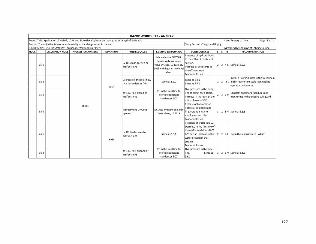
127
NODE DESCRIPTION NODE PROCESS PARAMETERS DEVIATION POSSIBLE CAUSE EXISTING SAFEGUARDS CONSEQUENCES S L R RECOMMENDATION
5.5.1LV 1015 fails opened or
malfunctions
Manual valve GWCS03,
Bypass system around
valve LV 1015, LG 1019, LIC
1015 with high an low leval
alarm
Presence of hydrocarbons
in the effluent treatment
section.
Increase of pollutants in
the effluent water.
Economic losses
2 2 4-L Same as 5.3.1
5.5.2Decrease in the inlet flow
rate to condenser D-01 Same as 5.3.2
Same as 5.3.1
Same as 5.5.12 2 4-L
Install a flow indicator in the inlet line of
olefin regenerant coalescer. Realize
operator procedures.
5.5.3XV 1353 fails closed or
malfunctions
PP in the inlet line to
olefin regenerant
condenser E-02
Overpressure in the outlet
line to olefin feed driers.
Increase in the level of the
driers. Same as 5.5.2
2 3 6-MConstant operator procedures and
monitoring to the existing safeguard
5.5.4Manual valve GWCS03
opened
LIC 1015 with low and high
level alarm, LG 1019
Release of hydrocarbon.
Potential explosion and
fire. Potential risk to
employees and plant.
Economic losses
3 2 6-M Same as 5.5.3
5.6.1LV 1015 fails closed or
malfunctions Same as 5.5.1
Presence of water in D-02.
Decrease in the lifetime of
the olefin feed driers D-03
A/B due an increase in the
water present in the
stream .
Economic losses.
2 2 4-L Open the manual valve LWCS03
5.6.2XV 1353 fails opened or
malfunctions
PP in the inlet line to
olefin regenerant
condenser E-02
Overpressure in the pipe
line. Same as
5.6.1
3 2 6-M Same as 5.5.3
LEVEL
HIGH
LESS
HAZOP WORKSHEET - ANNEX 2 Project Title: Application of HAZOP, LOPA and SIL to the alkylation unit catalyzed with hydrofluoric acid
Process: The objective is to remove humidity of the charge currents the unit Study Section: Charge and Drying
HAZOP Team: Figueroa Stefanny, Lombana Stefany and Ruiz Ingry Meeting days: All days of Febrary to June
Date: Febrary to June Page 1 of 1

128
Annex 3 Application of HAZOP methodology to Reaction section
NODE DESCRIPTION
NODEPROCESS PARAMETERS DEVIATION POSSIBLE CAUSE EXISTING SAFEGUARDS CONSEQUENCES S F R RECOMMENDATION
1.1.1
Increase in the inlet flow
from of the Charge and Drying
section due to problem
operational
FIC1059C/1903C
Economically inefficient operation.
Possible acid drag to isostripper section
due to speedup in reactors. Decrease in
the alkylate octanaje. Increase in the
polymer production and pollutans.
2 1 2-L
Install a flow indicator in the inlet
line when the streams are mixed to
verify that the flow is right
1.1.2
The inlet stream of HF more
cooler than normal due to
operational problems in the
ALKAD section or Acid settler
D-04
TI1055/1907 Economically inefficient operation. 3 1 3-L
Periodic inspection and maintenance
of temperature indicators to avoid
operational problems in the reactors
1.1.3
The inlet stream of
Isobutane/Olefins more
cooler than normal due to
operational problems in the
Charge and Drying section or
Isostripper section
PI 1053/1905
Increase the production of organics
fluorides.
Loss of acid
3 1 3-L Same as 1.1.2
1.1.4Increase in the primary
cooling water inlet flow rate FI1328, TI1330, PI1332, TI 1548, PI1546
Much cooling causing reactor cool.
Possible rupture in the pipes due to
overpressure. Economically inefficient
operation
4 1 4-L
Installation of a cooling water flow
indicator and low flow alarm to
provide an immediate indication of
cooling loss. Periodic inspections
and maintenance of the cooling
system to insure its integrity.
1.1.5Increase in the isobutene
recirculation flow rate TI1054/1906; FIC1047/1900
Economically inefficient operation.
Possible acid drag to isostripper section
due to speedup in reactors.
3 1 3-L Same as 1.1.2
1.2.1Decreasing in the isobutene
stream of recirculation FIC1047/1900
Generation of polymer and pollutants
causing a decreasing the octanaje of
alkylate.Secondary reaction in downstream
equipment.
4 2 8-M
Periodic inspection and maintenance
of the controllers to prevent that
send bad signal to the control room
or valve
1.2.2Increasing of the temperature
of the inlet stream of HFSame as 1.1.2 Same as 1.2.1 4 2 8-M Same as 1.1.2
1.2.3
Increasing of the temperature
of the inlet stream of the
isobutane and olefins
Same as 1.1.3 Same as 1.2.1 4 2 8-M Same as 1.1.2
REACTOR
E28/28A1
HAZOP WORKSHEET - ANNEX 3 Project Title: Application of HAZOP, LOPA and SIL to the alkylation unit catalyzed with hydrofluoric acid Date: Febrary to June Page 1 of 1
Process: Explains the reaction between the olefins and isobutane in the presence of hydrofluoric acid to obtain the alkylate Study Section: Reaction
HAZOP Team: Figueroa Stefanny, Lombana Stefany and Ruiz Ingry Meeting days: All days of Febrary to June
LESS
HIGH
TEMPERATURE

129
NODE DESCRIPTION
NODEPROCESS PARAMETERS DEVIATION POSSIBLE CAUSE EXISTING SAFEGUARDS CONSEQUENCES S F R RECOMMENDATION
1.2.4 TEMPERATURE HIGH
The cooling flow is
interrupted due to the FBCF01
fails closed
TI 1548, PI1546
Runaway reaction with subsequent
increase in the vessel pressure possibly
leading to a rupture or explosion of the
vessel
4 3 12-S
Installation of a cooling water flow
indicator and low flow alarm to
provide an immediate indication of
cooling loss. Periodic inspections
and maintenance of the cooling
system to insure its integrity.
Installation of a high temperature
alarm to alert the operator in the
event of cooling function loss.
Installation of a high temperature
shutdown system, that would
automatically shutdown the process
in the event of a high reactor
temperature. The shutdown
temperature would be higher than
the alarm temperature to provide
the operator with the opportunity to
restore cooling before the reactor is
shutdown. Evaluation of the cooling
water source to consider any
possible interruption and
contamination of the supply.
1.3.1 LESSPI 1905 or PI 1053 fails send a
bad signal PI 1052; PI 1904
Decrease in the operation conditions
causing inefficiency in the reactor2 2 4-L
Constantly monitoring of the
controllers to avoid undesirable
reactions and maintain the
production of alkylate
1.4.1
Increasing of the temperature
in the reactors due the inlet
stream is more higher than
normal or the cooling streams
is less than normal
TI 1054/1548/1055, PI 1053/1052/1546
Overpressure in the reactors
Increase of the production polymer and
contaminants
Increased loss of acid
Economic losses
4 1 4-L
Same as 1.3.1
Monitoring of the cooling system to
maintain the operation temperature
in the range of operating
1.4.2
PSV 1048/1915 fails closed
causing an overpressure in
the cooling pipe
PI 1547/1916, TI 1049/1917
Rupture in the cooling pipe causing water
spill and problems in the operation
condition. Problems in
the operation condition of the reactors
3 2 6-M
Monitoring of the cooling pipe and
PSV valve to avoid an incident and
maintain the good operation in the
reactors
Install a PIC in the exit of the cooling
pipe to control the pressure from the
control room
REACTOR
E28/28A1
HAZOP WORKSHEET - ANNEX 3 Project Title: Application of HAZOP, LOPA and SIL to the alkylation unit catalyzed with hydrofluoric acid Date: Febrary to June Page 1 of 1
Process: Explains the reaction between the olefins and isobutane in the presence of hydrofluoric acid to obtain the alkylate Study Section: Reaction
HAZOP Team: Figueroa Stefanny, Lombana Stefany and Ruiz Ingry Meeting days: All days of Febrary to June
HIGH
PRESSURE

130
NODE DESCRIPTION
NODEPROCESS PARAMETERS DEVIATION POSSIBLE CAUSE EXISTING SAFEGUARDS CONSEQUENCES S F R RECOMMENDATION
1.5.1FIC 1059C/1903C fails closed
the FV 1059/1903 valve
Bypass system LBCF06 located in each
reactor around of the FV 1059/1903
valve
Decrease of octane alkylate product
Increase in the end point of alkylate
Increase in the polymer material
Increase of acid lost
5 2 10-M
Activate bypass system to control of
the flow in case that fails
Constant monitoring of the pipeline
to avoid tamponade due to the
contaminants
1.5.2
Isobutane flow FIC 1047/1900
fails closed the FV 1047/1900
valve
Bypass system LBCF09 located in each
reactor around of the FV 1047/ 1900
valve
Same as 1.5.1
Increase in the temperature
Could occur secundary reactions in the acid
settler and in the top of the isostripper
5 2 10-M Same as 1.5.1
1.5.3
Acid and aditive HC 1056 and
1908 fails closed the HV
1056/1908 valves
FE 1057/1909; FIC 1059C/1903C; TI
1056/1907Point increase in volatility acid 3 3 9-M
Decreasing of the flow of olefins and
butane to maintain the operation
Maintenance the pipe to avoid
tamponade or leak
Install an alarm flow indicator and a
bypass sistem in case that the valve
fails closed and maintain the flow in
the reactors
1.5.4
Rupture or hole in the pipe of
the Isubutane stream due to
the corrosion or overpressure
FIC 1047/1900 - PI 1053/1905
Same as 1.5.2
Posible fire explosion
Air pollution Personal
Injures
Economic losses
5 1 5-M
Constant monitoring to the pipe line
to avoid rupture and prevent an
incident
Decrease of the flow of olefins and
isobutane to prevent an incident
Close the valves FV 1047/1900 to cut
the flow input
1.5.5
Rupture or hole in the pipe of
the olefins stream due to the
corrosion or overpressure
FIC 1059C/1905 - PI 1053/ 1905
Same as 1.5.1 Posible fire
explosion Air
pollution Personal
Injures
Economic losses
5 1 5-M
Constant monitoring to the pipe line
to avoid rupture and prevent an
incident
Decrease of the flow of olefins to
prevent an incident
Close the valves FV 1059/1903 to cut
the flow input
1.5.6
Rupture or hole in the pipe of
the HF and aditive stream due
to corrosion or overpressure
HC 1056/1908
Same as 1.5.3 Catastrophic
events like, personal injuries event with
fatalities
5 2 10-M
Constant monitoring to the pipe line
to maintain the operation and avoid
a rupture
Install a bypass system and alarm
flow indicator in case that the valve
fails closed and show the inlet flow
1.5.7
Tamponade in the pipe of the
streams of HF and Additive
due to the accumulation of
the contaminants
HC 1056/1908
Same as 1.5.6 Overpresure
in the line Posible fire
explision
5 1 5-M
Constant monitoring to the pipe line
to maintain the operation and avoid
a tamponade
1.5.8
Both pumps P-02A/C stop
from loss of power (Normally
operate two
pumps).
FI 1057/1909; Pump run status in PCS
Total loss of acid flow to
both reactors leading to
uncontrolled ratio of HC/acid. With
continued HC feed flow,
this can result in the potential
for polymer formation and
eventually acid runaway.
Potential for increased
corrosive environment which
could result in leaks in process, with
possible
personnel exposure to HF
4 2 8-M
Maintenance of the pumps to avoid
stop of operation and maintain the
feed of the acid to the reactors
REACTOR
E28/28A1
HAZOP WORKSHEET - ANNEX 3 Project Title: Application of HAZOP, LOPA and SIL to the alkylation unit catalyzed with hydrofluoric acid Date: Febrary to June Page 1 of 1
Process: Explains the reaction between the olefins and isobutane in the presence of hydrofluoric acid to obtain the alkylate Study Section: Reaction
HAZOP Team: Figueroa Stefanny, Lombana Stefany and Ruiz Ingry Meeting days: All days of Febrary to June
LESSLEVEL

131
NODE DESCRIPTION
NODEPROCESS PARAMETERS DEVIATION POSSIBLE CAUSE EXISTING SAFEGUARDS CONSEQUENCES S F R RECOMMENDATION
1.6.1
The controllers of the Olefins
stream which are FIC 1059
C/1903 C fails, opening the FV
1059/1903 valves
Bypas system, GBCF16 Manual valve
located after of the FV1059 valve;
GBCF 16 Manual valve located after of
the FV 1903 valve; TI 1051/1911; PI
1053/1905
Decrease in the flow rate of isobutane/
olefins flow
Decrease of octane final product
Increase in the alkylate final point
Increase in the polimeric material
Increase acid losess
3 1 3-L
Install FI after the FV 1903/1059 valve
to show the flow inlet in the reactors
and maintain the relation
isobutane/olefins and HF/HC
Constantly monitoring to the
controllers to avoid fails in the
operation
1.6.2
The controllers of the
Isobutane stream which are
FIC 1047/1900 fails opening
the FV 104771900 valves
GBCF22 Manual valve located after of
the FV 1047 valve; GBCF 22 Manual
valve located after of the FV 1900
valve
Increase of octane of the alkylate product
decrease in the polimeric material
Economic operation inefficient
Acid escape to the destilation separation
column
4 1 4-L Same as 1.6.1
1.6.3
The controllers of the Acid
and aditive stream which are
HC 1056/1908 fails opening
the HV 1056/1908 valves
Same as 1.5.3 Catalyst deactivation 3 3 9-M
Install FIC after the HV 1908/1056 and
loops work which work with those
valves
1.7.1
Rupture or hole in the charge
and drying pipe line due to
the overpressure or corrosion
GBCF 22 Manual valve located in each
reactor before of the PI 1052/1904; XV
1060 / 1902; PI 1052 / 1904; PI 1053 /
1905
Posible fire explosion Air pollution
Decrease in the alkylate product
Decrease in the generation of polynmeric
materials Decrease in the
alkylate product Increase in
the temperature of the E-28/28A
Economic losses
5 2 10-M
Constant maintenance of the pipe
line to prevent rupture or fails in the
process
Activate bypass system and interrupt
the inlet flow
1.7.2
Tamponade in the inlet pipe
due to the accumulation of
contaminants in the pipe
PI 1052/ 1904; PI 1053/1905Overpressure in the pipe line
Same as 1.7.15 2 10-M
Constant maintenance of the pipe
line to prevent rupture or fails in the
process
1.7.3FIC 1047/1900 fails closed the
FV 1047/1900 valve
Bypass system LBCF 09; GBCF22
Desviation valve; FE 1047/1900
Decrease of octane alkylate product
Increased loss of acid
Presence of secondary reactions in the
equipment D-04, D-05 and top of the tower
V-02 Same as
1.7.2
4 1 4-L
Maintenance of the Bypass system to
maintain the flow and prevent
operational problems in the reactors
1.7.4
The line from of Charge and
Drying of the controllers FIC
1059C/1903C fails, closed the
FV 1059/1903 valve
Bypass system LBCF06; FE 1059/1903 Increase of octane alkylate product
Same as 1.7.25 1 5-M Same as 1.7.3
1.7.5
Fails in the relacionador of
Isobutane to Olefins XI
2508/2512 closing the
FV1059C / 1903C or FV
1047/1900 valves
Bypass system LBCF 06/09, TI
1051/1911; PI 1053/1905
Decrease in the octane of product alkylate
Increasse in the final point of alkylate
Generation of polymer material
Increase in the acid lost
3 2 6-M
Constant monitoring of loops control
to avoid fails in the process and
prevent that the valves fails closed
1.7.6
The XV 1060/1902 valve of
the pipe from of the Charge
and Drying section fails closed
FE 1059/1903 Same as 1.7.4 3 2 6-M
Maintenance of the XV 1060/1902
valve to avoid a decreasing of the
relation of the olefins and isobutane
and maintain the alkylate quality
LEVEL
RELATION ISOBUTANE -
OLEFINSLESS
HAZOP WORKSHEET - ANNEX 3 Project Title: Application of HAZOP, LOPA and SIL to the alkylation unit catalyzed with hydrofluoric acid Date: Febrary to June Page 1 of 1
Process: Explains the reaction between the olefins and isobutane in the presence of hydrofluoric acid to obtain the alkylate Study Section: Reaction
HAZOP Team: Figueroa Stefanny, Lombana Stefany and Ruiz Ingry Meeting days: All days of Febrary to June
HIGH
REACTOR
E28/28A1
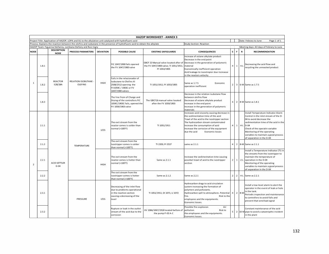
132
NODE DESCRIPTION
NODEPROCESS PARAMETERS DEVIATION POSSIBLE CAUSE EXISTING SAFEGUARDS CONSEQUENCES S F R RECOMMENDATION
1.8.1FIC 1047/1900 fails opened
the FV 1047/1900 valve
GBCF 22 Manual valve located after of
the FV 1047/1900 valve; TI 1051/1911;
PI 1053/1905
Increase of octane alkylate product
Decrease in the end point
Decrease in the generation of polymeric
material
Economically inefficient operation
Acid leakage to issostropier due increasse
in the reactors velocity
4 1 4-LDecreasing the acid flow and
recycling the unreacted product
1.8.2
Fails in the relacionador of
Isobutane to Olefins XI
2508/2512 opening the
FV1059C / 1903C or FV
1047/1900 valves
TI 1051/1911; PI 1053/1905Same as 1.7.5 Economic
operation inefficient2 3 6-M Same as 1.7.5
1.8.3
The line from of Charge and
Drying of the controllers FIC
1059C/1903C fails, opened the
FV 1059/1903 valve
The GBCF16 manual valve located
after the FV 1059/1903
Decrease in the relation isubotane flow
between olefins flow
Decrease of octane alkylate product
Increase in the end point
Increase in the generation of polymeric
materials
4 2 8-M Same as 1.8.1
2.1.1
The exit stream from the
reactor comes is colder than
normal (<100°F)
TI 1051/1911
Increases acid viscosity causing decrease in
the sedimentation time of the acid
Trawl of the acid to the isostripper section
The hydrocarbon stream contaminated
Increase the consumption of acid
Increase the corrosion of the equipment
due the acid Economic losses
4 1 4-L
Install Temperature Indicator Alarm
Control in the inlet stream of the D-
04 to avoid decrease the
sedimentation time of the acid in the
D-04
Check of the operatin variable
Monitoring of the operating
variables to maintain a good process
of separation in the D-04
2.1.2
The exit stream from the
Isostripper comes is colder
than normal (<100°F)
TI 2359; PI 2537 same as 2.1.1 4 2 8-M Same as 2.1.1
2.2.1
The exit stream from the
reactor comes is hotter than
normal (>100°F)
Same as 2.1.1
Increase the sedimentation time causing
possibel trawl of acid to the isostripper
section
2 1 2-L
Install a Temperature Indicator (TI) in
the streams from the isostripper to
maintain the temperature of
operation in the D-04
Monitoring of the operating
variables to maintain a good process
of separation in the D-04
2.2.2
The exit stream from the
isostripper comes is hotter
than normal (>100°F)
Same as 2.1.2 Same as 2.2.1 2 2 4-L Same as 2.2.1
2.3.1
Decreasing of the inlet flow
due to problems operational
in the reaction section
causing a decreasing of the
level
TI 1051/1911; DI 1071; LI 1072
Hydrocarbon drags to acid circulation
system increasing the formation of
polymers and pollutants.
Hydrocarbon spill to atmosphere. Potential
fire. Risk to the
employees and the equipments.
Economic losses.
4 2 8-M
Install a low level alarm to alert the
operator in the event of leak or hole
in the tank.
Periodic inspection and maintenance
to controllers to avoid fails and
prevent that send bad signal
2.3.2
Rupture or leak in the outlet
stream of the acid due to the
corrosion
XV 1066/1067/1918 located before of
the pump P-02 A-C
Possible fire explosion Air
pollution Risk to
the employees and the equipments.
Economic losses.
5 2 10-M
Constant maintenance of the acid
pipe to avoid a catastrophic incident
in the plant
REACTOR
E28/28A
RELATION ISOBUTANE -
OLEFINS1
PRESSURE
ACID SETTLER
D-04 2
HIGH
LESS
LESS
HIGH
TEMPERATURE
HAZOP WORKSHEET - ANNEX 3 Project Title: Application of HAZOP, LOPA and SIL to the alkylation unit catalyzed with hydrofluoric acid Date: Febrary to June Page 1 of 1
Process: Explains the reaction between the olefins and isobutane in the presence of hydrofluoric acid to obtain the alkylate Study Section: Reaction
HAZOP Team: Figueroa Stefanny, Lombana Stefany and Ruiz Ingry Meeting days: All days of Febrary to June

133
NODE DESCRIPTION
NODEPROCESS PARAMETERS DEVIATION POSSIBLE CAUSE EXISTING SAFEGUARDS CONSEQUENCES S F R RECOMMENDATION
2.4.1
Tamponade in the outlet pipe
(draining HF pipe) causing
increase in the acid level
LI 1072; PI 1069
Hydrofluoric acid drags to isostripper
section Overpressure in the
D-04
4 2 8-M
Maintenance of the acid pipe to
avoid accumulation of contaminant
in the pipe and prevent operational
problems in the reaction section
2.4.2
Tamponade in the outlet pipe
(draining alkylate and
isobutane pipe)
PI 1069
Higher content of polymer in the stream.
Low density making efficient separation of
emulsion Overpressure in the D-04
3 2 6-M
Maintenance of the alkylate and
isobutane pipe to avoid
accumulation of contaminant in the
pipe and prevent operational
problems in the next section
2.4.3
The XV 2461 valve located in
the isobutane and alkylate
pipe fails closed
Same as 2.4.2
Increase the level in the vessel causing
trawl of isobutane and alkylate to the
reaction section
Overpressure in the D-04
2 3 6-M
Monitoring of the XV 2461 valve to
avoid fails closed and maintain the
operation in the next section
2.4.4 PSV 1990 fails closed LBCF09 deviates the flow to the HF
Acid Blowdown
Overpressure in the D-04. Increasing of the
temperature inside of the D-04 3 2 6-M
Maintenance of the PSV 1990 to
prevent that fails closed and avoid a
explosion due to the overpressure
2.5.1
Rupture in the inlet pipe of
the D-04 due to the
overpressure in the pipe
TI 1051/1911
Posible fire explotion
Air pollution due an acid escape
Equipment damage Risk to
the employees
Economic losses
5 2 10-M
Constant monitoring in the pipeline
to avoid problems in the process
Install a pressure indicator in the line
to show the pressure and maintain
the operation
2.5.2
XV 1066 valve located before
of the pump P-02A fails
opened
Same as 2.4.1
Damages mechanic in the pumps
Operational problems in the reactors E-
28/28A
Cavitation in the pumps
5 2 10-M
Monitoring of the XV 1066 valve to
avoid fails closed and maintain the
operation in the reactors to obtain a
good alkylate
2.5.3
Decreasing of the inlet stream
compound with acid,
isobutane and alkylate is less
due to operational problems
in the reactors
Same as 2.1.1
Bad separation of the acid in the D-04
Inefficiency in the separation in the
isostripper section
Trawl of hydrocarbon to the reaction
section
5 2 10-M
Monitoring of the proces in the
reactors E-28/28A to maintain the
production of alkylate and reduce
fails in the D-04
2.5.4
Rupture or leak in the outlet
stream of the acid due to the
corrosion
Same as 2.3.2 Same as 2.3.2 4 2 8-M Same as 2.3.2
2.5.6
Tamponade in the inlet pipe
of the D-04 due to the
increase of contaminants in
the pipe
Same as 2.5.1
Operational problems in the reactors E-
28/28A Decreasing of the
quality of the alkylate
Overpressure in the pipeline
3 2 6-M
Install a pressure indicator in the
inlet pipe to show that the pipe no is
obstructed
2.6.1
Increasing of the inlet stream
compound with acid,
isobutane and alkylate is less
due to operational problems
in the reactors
Same as 2.1.1
Trawl of acid to the Isostripper scetion
Bad separation in the D-04
Contamination of the stream that enter to
the reaction section
4 1 4-L Same as 2.5.3
2.6.2 XV 1066 valve fails closed Same as 2.4.1
Trawl of acid to the isostripper section
Contamination of the alkylate and
isobutane stream
Economic losses
3 3 9-M
Monitoring of the XV 1066 valve to
avoid fails opened and maintain the
operation in the reactors to obtain a
good alkylate
2.6.3 XV 2461 valve fails closed PI 1069; LI 1072; PSV 1990; DI 1071
Trawl of alkylate and isobutane to the
reaction section
Operational problems in the isostripper
section
3 2 6-M
Constant monitoring of the XV 2460
valve to avoid that fails closed and
prevent bad control in the reactors E-
28/28A
PRESSURE
ACID SETTLER
D-04 2
HIGH
LEVEL
LESS
HIGH
HAZOP WORKSHEET - ANNEX 3 Project Title: Application of HAZOP, LOPA and SIL to the alkylation unit catalyzed with hydrofluoric acid Date: Febrary to June Page 1 of 1
Process: Explains the reaction between the olefins and isobutane in the presence of hydrofluoric acid to obtain the alkylate Study Section: Reaction
HAZOP Team: Figueroa Stefanny, Lombana Stefany and Ruiz Ingry Meeting days: All days of Febrary to June

134
Annex 4 Application of HAZOP methodology to Acid Storage section
NODE DESCRIPTION NODE PROCESS PARAMETERS DEVIATION POSSIBLE CAUSE EXISTING SAFEGUARDS CONSEQUENCES S F R RECOMMENDATION
1.1.1PV 1033 fails closed or
malfunctions
PIC 1033, PI 1034, Bypass
system around valve PV
1033, PI 1035 with high and
lower pressure alarm, XI
1037 reference of level
Inefficient displacement
of HF causing increase in
the level in the truck
1 4 4-L
The line has enough safeguards.
Periodic maintenance to the
controls and valves. Also, operator
procedures, inspections and
training.
1.1.2PSV 1032 fails opened or
malfunctionsManual valve GWCS03
Nitrogen to ATM at safe
location. Same as 1.1.1 1 3 3-L
Consider if it is possible install a
bypass system around safety valve
PSV 1032
1.2.1PV 1033 fails opened or
malfunctions
PIC 1033, XV 1039, interlock
UC03, emergency shutdown
Overpressure in the
system. Shutdown safety
valve to D-30, increase in
the losses of acid. HF can
escape by breaking the
flexible lines, HF leak in
the truck for the block
valves.
2 2 4-L
Same as 1.1.1. Confirm that the HF
Acid vendor container has
overpressure protection.
Note: UOP recommends using the
minimum design pressure of the
vendor container 125 psig assuming
a 95 psig Nitrogen design pressure.
1.2.2
Tamponade in the outlet
pipe causing level
increase in the truck
PI 1035 with high and lower
pressure alarm, PI 1036
Increase in the truck level
causing overpressure in
the system. Possible
explosion due to
overpressure and release
of HF with potential risk o
employees and
sourronding areas.
Economic losses
3 2 6-M
Periodic maintenance to the pipe
and eliminate the presence of
pollutants in the tank to avoid
sedimentation in the pipe. Periodic
operator procedures, inspections
and training.
1.3.1 LESS Considered but nothing
significant identified
1.4.1Rupture in the N2 line or
NO flow of nitrogen
PIC 1033, PI 1034, Bypass
system around valve PV
1033
Same as 1.1.1 1 4 4-L Same as 1.1.1
1.4.2 Tamponade in the outlet
pipe
PI 1035 with high and lower
pressure alarm, PI 1036 Same as 1.2.2 3 2 6-M Same as 1.2.2
1.4.3XV 1040 malfunctions
closed
PI 1035 with high and lower
pressure alarm, PSV 1032
Expose the container to
the full nitrogen supply
pressure resulting in
potential overpressure
leading to possible leaks
of HF. Personnel safety
issues
3 2 6-M
Confirm that the HF Acid vendor
container has overpressure
protection.
Note: UOP recommends using the
minimum design pressure of the
vendor container 125 psig assuming
a 95 psig Nitrogen design pressure.
HAZOP Team: Figueroa Stefanny, Lombana Stefany and Ruiz Ingry Meeting days: All days of Febrary to June
HAZOP WORKSHEET - ANNEX 4 Project Title: Application of HAZOP, LOPA and SIL to the alkylation unit catalyzed with hydrofluoric acid Date: Febrary to June Page 1 of 1
Process: Describe the storage system, recirculation and drainage of hydrofluoric acid Study Section: Acid Storage
PRESSURE
HIGH
LESS
LEVEL
HIGH
HF ACID CONTAINER
(TRUCK) 1
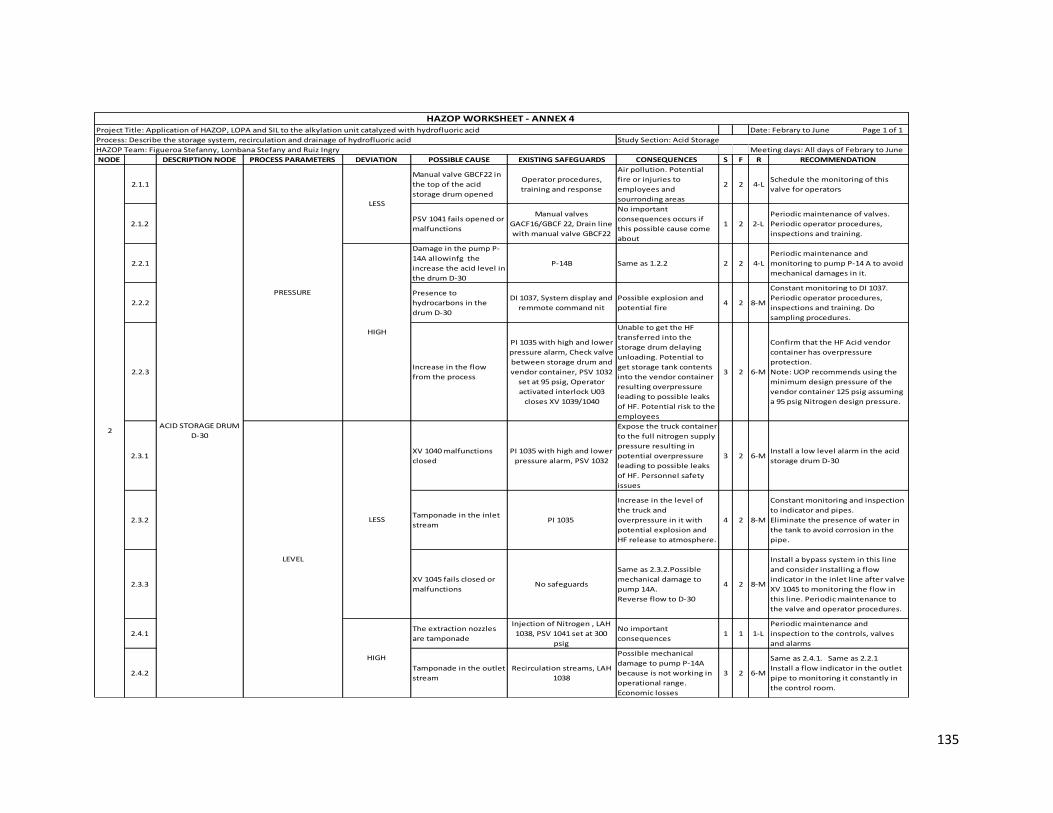
135
NODE DESCRIPTION NODE PROCESS PARAMETERS DEVIATION POSSIBLE CAUSE EXISTING SAFEGUARDS CONSEQUENCES S F R RECOMMENDATION
2.1.1
Manual valve GBCF22 in
the top of the acid
storage drum opened
Operator procedures,
training and response
Air pollution. Potential
fire or injuries to
employees and
sourronding areas
2 2 4-LSchedule the monitoring of this
valve for operators
2.1.2 PSV 1041 fails opened or
malfunctions
Manual valves
GACF16/GBCF 22, Drain line
with manual valve GBCF22
No important
consequences occurs if
this possible cause come
about
1 2 2-L
Periodic maintenance of valves.
Periodic operator procedures,
inspections and training.
2.2.1
Damage in the pump P-
14A allowinfg the
increase the acid level in
the drum D-30
P-14B Same as 1.2.2 2 2 4-L
Periodic maintenance and
monitoring to pump P-14 A to avoid
mechanical damages in it.
2.2.2
Presence to
hydrocarbons in the
drum D-30
DI 1037, System display and
remmote command nit
Possible explosion and
potential fire 4 2 8-M
Constant monitoring to DI 1037.
Periodic operator procedures,
inspections and training. Do
sampling procedures.
2.2.3Increase in the flow
from the process
PI 1035 with high and lower
pressure alarm, Check valve
between storage drum and
vendor container, PSV 1032
set at 95 psig, Operator
activated interlock U03
closes XV 1039/1040
Unable to get the HF
transferred into the
storage drum delaying
unloading. Potential to
get storage tank contents
into the vendor container
resulting overpressure
leading to possible leaks
of HF. Potential risk to the
employees
3 2 6-M
Confirm that the HF Acid vendor
container has overpressure
protection.
Note: UOP recommends using the
minimum design pressure of the
vendor container 125 psig assuming
a 95 psig Nitrogen design pressure.
2.3.1 XV 1040 malfunctions
closed
PI 1035 with high and lower
pressure alarm, PSV 1032
Expose the truck container
to the full nitrogen supply
pressure resulting in
potential overpressure
leading to possible leaks
of HF. Personnel safety
issues
3 2 6-M Install a low level alarm in the acid
storage drum D-30
2.3.2 Tamponade in the inlet
stream PI 1035
Increase in the level of
the truck and
overpressure in it with
potential explosion and
HF release to atmosphere.
4 2 8-M
Constant monitoring and inspection
to indicator and pipes.
Eliminate the presence of water in
the tank to avoid corrosion in the
pipe.
2.3.3 XV 1045 fails closed or
malfunctions No safeguards
Same as 2.3.2.Possible
mechanical damage to
pump 14A.
Reverse flow to D-30
4 2 8-M
Install a bypass system in this line
and consider installing a flow
indicator in the inlet line after valve
XV 1045 to monitoring the flow in
this line. Periodic maintenance to
the valve and operator procedures.
2.4.1 The extraction nozzles
are tamponade
Injection of Nitrogen , LAH
1038, PSV 1041 set at 300
psig
No important
consequences 1 1 1-L
Periodic maintenance and
inspection to the controls, valves
and alarms
2.4.2 Tamponade in the outlet
stream
Recirculation streams, LAH
1038
Possible mechanical
damage to pump P-14A
because is not working in
operational range.
Economic losses
3 2 6-M
Same as 2.4.1. Same as 2.2.1
Install a flow indicator in the outlet
pipe to monitoring it constantly in
the control room.
HAZOP Team: Figueroa Stefanny, Lombana Stefany and Ruiz Ingry Meeting days: All days of Febrary to June
HAZOP WORKSHEET - ANNEX 4 Project Title: Application of HAZOP, LOPA and SIL to the alkylation unit catalyzed with hydrofluoric acid Date: Febrary to June Page 1 of 1
Process: Describe the storage system, recirculation and drainage of hydrofluoric acid Study Section: Acid Storage
2
HIGH
LESS
ACID STORAGE DRUM
D-30
HIGH
PRESSURE
LESS
LEVEL

136
NODE DESCRIPTION NODE PROCESS PARAMETERS DEVIATION POSSIBLE CAUSE EXISTING SAFEGUARDS CONSEQUENCES S F R RECOMMENDATION
3.1.1 PSV 1079 fails opened Manual valve GBCF22
The acid is send to
blowdown causing
economic losses.
1 2 2-L
Periodic monitoring to the pressure
control to avoid the open of PSV
1079 and do maintenance to the
safety valve. Reestablish the
set point
3.1.2 Decrease in the inlet N2
stream flow rate PI 1080, PI 1081
Inefficient displacement
of HF causing increase the
level
1 4 4-L
Install o replace the PI 1081 for a PIC
which works in a loop control with
valve XV1077 to avoid human error
3.1.3 XV 1077 fails opened Manual Valve GBCF22, FI
2516
Increase the level in the
acid dump header1 1 1-L Same as 3.1.2
3.2.1 Increase in the inlet N2
stream flow rate PSV 1079. PI 1080, PI 1081
Displacement of HF to the
acid dump header.
Possible explosion in the
drum causing HF release
and possible injuries to
the employees. Air
pollution. Economic
losses.
2 2 4-L Install a shutdown system to cut the
inlet flow of N2. Same as 3.1.2
3.2.2
Increase in the level
inside the drum or dump
is full
LAH 1083 and LAHH 1078
radioactive high level
alarm, LI 1082 with high
level
alarm on D-23, PI-1081 with
high pressure alarm PI 1061
, PI 1080
HF drag to HF
blowdown.Possible
explosion in the drum
causing HF release.
Unable to remove the acid
from the system during an
emergency dump. If there
is a leak, there is greater
potential for personnel
injury. Air pollution.
Economic losses
4 2 8-M
Install a high level alarm in the tank.
Also, install a pressure indicator in
the top of the tank to monitoring
this property. Verify the dump drum
capacity
3.2.3
Inadvertently have block
valves closed(these
valves must be open
when the unit is running
but can be closed during
startup for example
during a dryout
operation).
Valves are designed to
be locked open (LO), the
refinery has a safety
isolation system
Unable to remove the acid
from the system during an
emergency dump. If there
is a leak, there is greater
potential
for personnel injury.
4 2 8-M
Consider install a bypass system
around blck valves and realize
periodic operator procedures
3.3.1Insufficient time for
dumping a system.
The time is preset based
on design inventory
calculations.
Can't get all the acid out. If
there is a leak, there is
greater
potential for personnel
injury.
3 3 9-M
Once the piping design has been
completed, isometrics are to be
sent to UOP to address timing for
dumping acid from equipment. UOP
to verify and approve the unit dump
timing based on inventory and
piping layout. Flow test the acid
dump/pumpout system to verify the
timing of the dump sequence.
3.3.2 Tamponade in the inlet
stream FI 2516
Overpressure in the line
causing vibration in it with
possible explosion and
potential release of acid.
Potential risk to
employees and
sourronding areas. Air
pollution. Economic losses
2 3 6-M
Install a pressure indicator in the
inlet stream and a PSV to send the
acid to another vessel (header).
3.4.1 HIGH Increase in the inlet
flow rate
XV 1077, FI 2516, LAHH 1078
radioactive high level
alarm
Same as 3.2.2 4 2 8-M Same as 3.2.2
HAZOP Team: Figueroa Stefanny, Lombana Stefany and Ruiz Ingry Meeting days: All days of Febrary to June
HAZOP WORKSHEET - ANNEX 4 Project Title: Application of HAZOP, LOPA and SIL to the alkylation unit catalyzed with hydrofluoric acid Date: Febrary to June Page 1 of 1
Process: Describe the storage system, recirculation and drainage of hydrofluoric acid Study Section: Acid Storage
3 ACID DUMP DRUM
LESS
HIGH
PRESSURE
LEVEL
LESS

137
Annex 5 Application of HAZOP methodology to Cooling Water Tower – TAE- section
NODE DESCRIPTION NODE PROCESS PARAMETERS DEVIATION POSSIBLE CAUSE EXISTING SAFEGUARDS CONSEQUENCES S F R RECOMMENDATION
1.1.1 LESS Considered but nothing
significant identified
1.2.1 HIGHBad functioning of cooling
tower fans
Pressure safety valves, run
status indicators for fan
motors, TI 1374, TI 1330, , TI
1379, TI 1335, Shutdown.
Higher cooling water
temperature. Potential
overpressure of the
alkylation unit leading to
flange leaks, loss of
containment causing
potential fire and
personnel injury.
5 2 10-M
Constant check of the process to
ensure the adequate functioning of
the unit. Check all the procedures
with the same goal include the
cooling water system failures.
1.3.1 LESS Decrease in the inlet flow
PI-2036 with low pressure
alarm on the cooling water
header, Pressure Safety
Valves, Pressure Safety
Valves, Electrical power is
provided by two separate
busses, Two of the electric
motor driven pumps are
connected to the
emergency power supply,
Selection and sizing of the
pump allows adequate
cooling, even while three
pumps are running
although with less pressure
cooling water system and
return temperatures higher
(normal operation is four
pumps in service), Two
steam turbines P-400A/E.
Potential for lower cooling
water supply pressure
resulting in lower flow
rates to the Alkylation
Unit. Potential to
overpressure leading to
flange leaks, loss of
containment with
potential for
fire and employees injury.
5 2 10-M Install a low pressure alarm on PI 1382
in the high pressure steam supply
1.4.1 HIGH
Cooling water supply
blocked in exchangers with
heat still on exchangers
PSVs in each heat
exchanger provided in the
cooling water side.
Potential overpressure
due to increase in the
temperature of the
cooling water side of the
heat exchanger causing
damage in it (leak).
2 2 4-L
Check the pressure in each cooling
water exchanger to guarantee the
correct operation of this and avoid
damage in the exchangers.
COOLING TOWER CT-
401
HAZOP WORKSHEET - ANNEX 5 Project Title: Application of HAZOP, LOPA and SIL to the alkylation unit catalyzed with hydrofluoric acid Date: Febrary to June Page 1 of 1
Process: Discusses the cooling system of the cooling water of unit Study Section: Cooling Water Tower TAE
HAZOP Team: Figueroa Stefanny, Lombana Stefany and Ruiz Ingry Meeting days: All days of Febrary to June
TEMPERATURE
PRESSURE
1

138
NODE DESCRIPTION NODE PROCESS PARAMETERS DEVIATION POSSIBLE CAUSE EXISTING SAFEGUARDS CONSEQUENCES S F R RECOMMENDATION
1.5.1
LV 2004 fails closed
decreasing the flow of
filtered water
PI 2036 with low pressure
alarm in the header, LI 2010
with low level alarm,
Bypass system, FI 2005,
PSVs.
Loss of cooling due to
decrease in the cooling
water basin level. Possible
overpressure and
explosions or leaks
causing loss of
containment with
potential fire and injuries
to the employees and
equipments. Decrease in
the flow rate due to
decrease in the pressure
causing damage in other
sections in the unit.
5 2 10-M
Constant check of this parameter and
revision of the existing safeguards.
Training to the operators to avoid
human errors.
1.5.2
Decrease in the flow rate of
chlorinated cooling water
makeup
Sampling, other treatment
procedures.
Grow up of biomass
afecting the operability in
the unit. Increase in the
fouling factor.
2 2 4-L
Periodic sampling procedures in the
treatment procedures. Training to the
operator to do this procedures safely.
1.5.3 AV 2026 fails closed
Bypass system, Sampling
procedures of the cooling
water. Other treatment
procedures.
Potential grow uo of
contaminants in the
cooling water. Increase in
the fouling factor.
2 2 4-L Same as 1.5.2
1.5.4 XV 2014 fails closed
Sampling procedures of the
cooling water. Other
treatment procedures.
Same as 1.5.3 2 2 4-L Same as 1.5.2
1.5.5 XV 2013 fails closed Same as 1.5.4 Same as 1.5.3 2 2 4-L Same as 1.5.2
1.5.6 XV 2012 fails closed Same as 1.5.4 Same as 1.5.3 2 2 4-L Same as 1.5.2
1.6.1 HIGH LV 2004 fails open
LI 2010, high level alarm,
Bypass system with a block
valve, FI 2005
Increase in the flow of
filtered water causing
potencial spill of this
water in the cooling tower
basin. Risk to the
employees and
environmental damage.
2 2 4-L
Periodic maintenance to the
safeguards and check the parameters
to avoid the spill of water.
1.7.1 Content of acid in the
cooling water system Sampling procedures.
Increase in the pH causing
toxic environment in the
cooling water. Possible
corrosion in the
equipment. Risk to the
employees.
3 2 6-M
Periodic realization of sampling
procedures and constantly measure
of ph.
1.7.2 Leak of hydrocarbon
AI 2003, interlock UC 31, AIC
2026, AI 2027, Additive to
maintain equipment
integrity, sampling
procedures.
Presence of hydrocarbon
in the cooling water
system. Possible fire and
employees injury.
4 3 12-SInstall a measuring element level low
(LEL) in the cooling system
1.7.3 Leak in the reactor AI 1050, AI 1912, AI 2028,, AI
2003
Presence of hydrocarbon
and acid in the cooling
water system causing
corrosion. Potential fire in
the section and
employees injuries.
3 2 6-M Maintenance to the reactor and
monitoring of the fluoride analyzer.
1.8.1 HIGH Considered but nothing
significant identified
1COOLING TOWER CT-
401
LESS
COMPOSITION (WATER
PURITY)
LESS
HAZOP WORKSHEET - ANNEX 5 Project Title: Application of HAZOP, LOPA and SIL to the alkylation unit catalyzed with hydrofluoric acid Date: Febrary to June Page 1 of 1
Process: Discusses the cooling system of the cooling water of unit Study Section: Cooling Water Tower TAE
HAZOP Team: Figueroa Stefanny, Lombana Stefany and Ruiz Ingry Meeting days: All days of Febrary to June
LEVEL
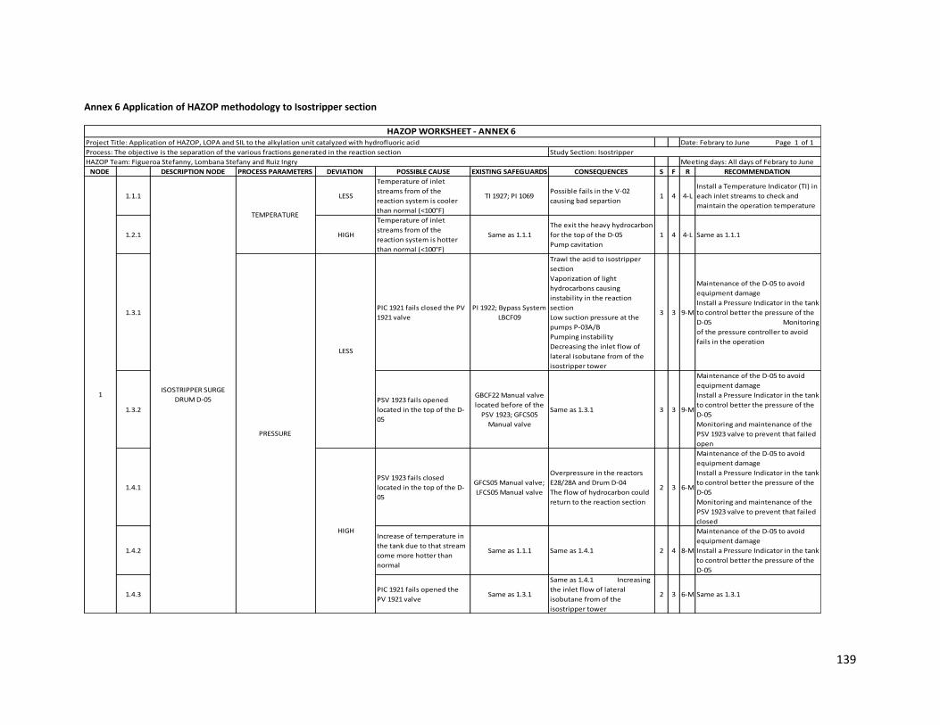
139
Annex 6 Application of HAZOP methodology to Isostripper section
NODE DESCRIPTION NODE PROCESS PARAMETERS DEVIATION POSSIBLE CAUSE EXISTING SAFEGUARDS CONSEQUENCES S F R RECOMMENDATION
1.1.1 LESS
Temperature of inlet
streams from of the
reaction system is cooler
than normal (<100°F)
TI 1927; PI 1069Possible fails in the V-02
causing bad separtion 1 4 4-L
Install a Temperature Indicator (TI) in
each inlet streams to check and
maintain the operation temperature
1.2.1 HIGH
Temperature of inlet
streams from of the
reaction system is hotter
than normal (<100°F)
Same as 1.1.1
The exit the heavy hydrocarbon
for the top of the D-05
Pump cavitation
1 4 4-L Same as 1.1.1
1.3.1PIC 1921 fails closed the PV
1921 valve
PI 1922; Bypass System
LBCF09
Trawl the acid to isostripper
section
Vaporization of light
hydrocarbons causing
instability in the reaction
section
Low suction pressure at the
pumps P-03A/B
Pumping instability
Decreasing the inlet flow of
lateral isobutane from of the
isostripper tower
3 3 9-M
Maintenance of the D-05 to avoid
equipment damage
Install a Pressure Indicator in the tank
to control better the pressure of the
D-05 Monitoring
of the pressure controller to avoid
fails in the operation
1.3.2
PSV 1923 fails opened
located in the top of the D-
05
GBCF22 Manual valve
located before of the
PSV 1923; GFCS05
Manual valve
Same as 1.3.1 3 3 9-M
Maintenance of the D-05 to avoid
equipment damage
Install a Pressure Indicator in the tank
to control better the pressure of the
D-05
Monitoring and maintenance of the
PSV 1923 valve to prevent that failed
open
1.4.1
PSV 1923 fails closed
located in the top of the D-
05
GFCS05 Manual valve;
LFCS05 Manual valve
Overpressure in the reactors
E28/28A and Drum D-04
The flow of hydrocarbon could
return to the reaction section
2 3 6-M
Maintenance of the D-05 to avoid
equipment damage
Install a Pressure Indicator in the tank
to control better the pressure of the
D-05
Monitoring and maintenance of the
PSV 1923 valve to prevent that failed
closed
1.4.2
Increase of temperature in
the tank due to that stream
come more hotter than
normal
Same as 1.1.1 Same as 1.4.1 2 4 8-M
Maintenance of the D-05 to avoid
equipment damage
Install a Pressure Indicator in the tank
to control better the pressure of the
D-05
1.4.3PIC 1921 fails opened the
PV 1921 valveSame as 1.3.1
Same as 1.4.1 Increasing
the inlet flow of lateral
isobutane from of the
isostripper tower
2 3 6-M Same as 1.3.1
ISOSTRIPPER SURGE
DRUM D-051
HAZOP Team: Figueroa Stefanny, Lombana Stefany and Ruiz Ingry Meeting days: All days of Febrary to June
HAZOP WORKSHEET - ANNEX 6 Project Title: Application of HAZOP, LOPA and SIL to the alkylation unit catalyzed with hydrofluoric acid Date: Febrary to June Page 1 of 1
Process: The objective is the separation of the various fractions generated in the reaction section Study Section: Isostripper
TEMPERATURE
LESS
HIGH
PRESSURE

140
NODE DESCRIPTION NODE PROCESS PARAMETERS DEVIATION POSSIBLE CAUSE EXISTING SAFEGUARDS CONSEQUENCES S F R RECOMMENDATION
1.5.1PIC 1921 fails closed the PV
1921 valve
Bypass LBCF09 located
in the inlet pipe of the
top of the D-05; PI 1922
increasing the inlet flow of
lateral isobutane from of the
isostripper tower
2 2 4-LMonitoring constantly of the PIC 1921
controller to prevent fails operating
1.5.2LIC 1924 or FIC 1933 fails
opened the FV 1933 valve
GBCF22 Manual valve
located before of the
FV 1933
Operation problems in the
isostripper section causing bad
separation
1 3 3-L
Install a Flow Indicator (FI) in the
inlet of the isostripper to show
correct flow for a good operation
1.5.3FIC 1932 fails closed the FV
1932 valve
Bypass LBCF09 located
in the reflux pipe of
the D-05
Same as 1.5.2 1 2 2-LMonitoring constantly of the FIC 1932
controller to prevent fails operating
1.5.4 XV 2461 fails closed PI 1069Same as 1.5.2
Same as 1.5.13 2 6-M
Maintenance of the valve to avoid a
decreasing in the level of the D-05
Install a Bypass system to maintain
the flow to the D-05
1.5.5
Tamponade of the inlet
pipe in the top due to
accumulation of the
contaminants
PIC 1921; PI1922Same as 1.5.1
Overpressure in the tank 3 3 9-M
Maintenance of the pipe to avoid
rupture of the pipe due to the
overpressure and an incident
1.5.6
Tamponade of the inlet
pipe in the bottom of the D-
05
TI 1927 Same as 1.5.5 3 2 6-M Same as 1.5.6
1.5.7Rupture in the inlet pipe of
the bottom of the D-05PI 1069
Possible fire explosion
Air pollution
Injuries to the employees
Equipment damage
Economic losses
5 3 15-S Same as 1.5.6
1.6.1PIC 1921 fails opened the
PV 1921 valve Same as 1.3.1
Instability in the control of the
pressure in the reaction section
Trawl of liquid hydrocarbon to
the Blowdown system
Pump gavitation
Operation problems in the
isostripper section
3 3 9-M Same as 1.5.1
1.6.2LIC 1924 or FIC 1933 fails
closed the FV 1933 valve
Bypass system LBCF09
located after of the FE
1933
Same as 1.6.1 2 3 6-M Same as 1.5.2
1.6.3FIC 1932 fails opened the FV
1932 valve
GBCF 22 Manual valve
located after of the FV
1932 valve
Same as 1.6.1 3 3 9-M Same as 1.5.3
1.6.4 XV 2461 fails opened Same as 1.5.7 Same as 1.6.1 3 2 6-M Same as 1.5.4
1.6.5 XV 1928/1930 fails closed
TI 1927; GBCF 22
Manual valve located
before of the TI 1927
Same as 1.6.1
Damage to the pump3 1 3-L
Maintenance of the valve to avoid a
increasing in the level of the D-05
1.6.6Tamponade in the exit pipe
of the D-05TI 1927 Same as 1.6.5 3 2 6-M Same as 1.5.5
1.7.1 NO Same as Less Same as Less Same as Less Same as Less
1ISOSTRIPPER SURGE
DRUM D-05
HAZOP Team: Figueroa Stefanny, Lombana Stefany and Ruiz Ingry Meeting days: All days of Febrary to June
LESS
HIGH
HAZOP WORKSHEET - ANNEX 6 Project Title: Application of HAZOP, LOPA and SIL to the alkylation unit catalyzed with hydrofluoric acid Date: Febrary to June Page 1 of 1
Process: The objective is the separation of the various fractions generated in the reaction section Study Section: Isostripper
LEVEL

141
NODE DESCRIPTION NODE PROCESS PARAMETERS DEVIATION POSSIBLE CAUSE EXISTING SAFEGUARDS CONSEQUENCES S F R RECOMMENDATION
2.1.1
Temperature of inlet
stream is cooler than
normal (<160° F)
TI 1562; TI 1563
Light leakage at the bottom
Alkylate pollution with HF
Increase the reflux flow in the
bottom
Greater energy supplied to the
column
Economic losses
3 3 9-M
Increase the flow in the E-11/11 A ,
the reboiler E-12 and the furnace H-
01
Decrease the reflux in the top
2.1.2 Increase of reflux in the topFIC 2319; XV 2317; LIC
1094
Presence of hydrocarburs and
alkylate in the top of the
column
Contamination of HF stream
2 3 6-M
Increase the reflux in the bottoms
and decrease the flow in the inlet of
the column
2.1.3Decrease of reflux in the
bottom
FIC 1499A; FIC 1500A;
FIC1501A; FIC 1502A;
PDIC 1107; XV2519
Same as 2.1.2 2 2 4-L
Decrease the reflux in the top
Decrease the flow in the inlet stream
Increase the fuel in the furnace and
reboiler
2.1.4
Decrease in the
temperature stream from
reboiler
TI 1565/ 1571
Vaporization and inefficient
separation
Increasse in the mount of
isobutene, propene and acid in
the bottom stream
Increase of the corrosion in
other section of the plant
3 2 6-MIncrease the reflux in the furnace
Decrease the reflux in the top
2.1.5
Decrease in the
temperature stream from
furnace
TI1106A-D; FIC1666;
PIC1662 A/B; PDIC1107Same as 2.1.4 3 1 3-L
Increase the temperature in the
reboiler Decrease the
reflux in the botoms
2.1.6Decrease in the inlet flow at
column FIC 1933; FIC1932
Operational problems at V-02
(Isostripper)
Prescence of HF in the botom
Corrosion in other section of
the plant
2 3 6-MDecrease the reflux in the top and
botoms
2.1.7XV 2519 Fails closed due to
malfunctions Vent System SIS UC14
Overpressure in the pipe line
Posible fire explosion
Increase the flow through
furneace
Possible flood on the plates of
the column
3 3 9-MActivate vent system to open the
valve
2.1.8
FIC 2100 fails opened due to
malfunctions
FI 2100 with bypass
system LWCS01 with
manual valves before
and after GBCSF01
Escape alkylate
Reduced flow within the
column
3 2 6-M
Install a manual valve before that FIC
to control and prevent possibles
overpressures and desviations
2.1.9TIC 1091 fails sending less
vapor
TI 1099; PSV 1361 with
manual valves before
and after control valve
GBCF13
Same as 2.1.4 2 4 8-M
Install a temperature alarm indicator
to avoid desviations and operational
inestabilities
ISOSTRIPPER TOWER V-02 TEMPERATURE 2
HAZOP Team: Figueroa Stefanny, Lombana Stefany and Ruiz Ingry Meeting days: All days of Febrary to June
HAZOP WORKSHEET - ANNEX 6 Project Title: Application of HAZOP, LOPA and SIL to the alkylation unit catalyzed with hydrofluoric acid Date: Febrary to June Page 1 of 1
Process: The objective is the separation of the various fractions generated in the reaction section Study Section: Isostripper
LESS

142
NODE DESCRIPTION NODE PROCESS PARAMETERS DEVIATION POSSIBLE CAUSE EXISTING SAFEGUARDS CONSEQUENCES S F R RECOMMENDATION
2.2.1
Temperature of inlet
stream is hot than normal
(>160°F)
TI 1562; TI 1563
Increase in the amount of
normal butane and alkylate
exiting the tower side draw
Low purity recycle isobutane
Possible activation of the
cutting system for high
temperature furnace
2 2 4-LDecrease the flow in the E-11/11A , In
the top and the bottoms
2.2.2Decrease of reflux in the
topFIC 2319; XV 2317
Presence of acid in the bottoms
Posible pollution in the outside
streams at bottoms
Possible corrosion in other
section of the plan
3 2 6-M
Decrease the reflux in the bottoms
Decrease the flow in the inlet of the
column
2.2.3Increase of reflux in the
bottom
FIC 1499A; FIC 1500A;
FIC1501A; FIC 1502A;
PDIC 1107; XV2519
Presence of butane and
alkylate in the top of the
column. Low
purity recycle isobutane
More energy from furnace,
economic losses
1 4 4-LIncrease the reflux in the top and
increase the flow at inlet stream
2.2.4Increase in the temperature
sream from reboiler TI 1565/ 1571
Same as 2.2.2
Economic losses for fuel and
contamination of the alkylate
3 3 9-MIncrease the reflux in the top and
decrease the reflux in the furnace
2.2.5Increase in the temperature
stream from furnace
TI1106A-D; FIC1666;
PIC1662 A/B; PDIC1107Same as 2.2.4 3 2 6-M
Decrease the steam flow from
reboiler and increase the flow in the
top
2.2.6Increase in the inlet flow at
column FIC 1933; FIC1932
Possible increase in the level
of D-05
Operational problems in the V-
02 for low flow
Presence of HF in the bottom
Possible corrosion in other
section of the plant
4 2 8-M
Increase the flow in the furnace and
more steam from reboiler is
requaried
2.2.7Isobutane leaking on the
top sideDrum sidestream D-07
Presence of HF in the bottom
Economic losses1 1 1-L Decrease the reflux from furnace
2.2.8 FIC 2100 fails closed FI 2100
Overpressure in the pipe line
Posible fire explosion
Increase in the reflux flow
Air pollution Risk
injures to employees
Economic losses
3 2 6-MInstall a bypass system
Decrease the inlet flow to column
2.2.9 Rupture in the inlet stream TI 1563; FIC 1933; FIC
1932
Air pollution
Possible fire explosion
Instability in the distillation
process
5 2 10-MInstall an flow indicator alarm in the
inlet
2.2.10Leak in the inlet stream
pipeline Same as 2.2.9 Same as 2.2.9 5 2 10-M Same as 2.2.9
TEMPERATURE ISOSTRIPPER TOWER V-022
HAZOP Team: Figueroa Stefanny, Lombana Stefany and Ruiz Ingry Meeting days: All days of Febrary to June
HAZOP WORKSHEET - ANNEX 6 Project Title: Application of HAZOP, LOPA and SIL to the alkylation unit catalyzed with hydrofluoric acid Date: Febrary to June Page 1 of 1
Process: The objective is the separation of the various fractions generated in the reaction section Study Section: Isostripper
HIGH
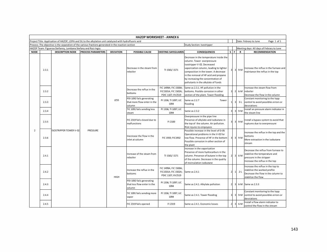
143
NODE DESCRIPTION NODE PROCESS PARAMETERS DEVIATION POSSIBLE CAUSE EXISTING SAFEGUARDS CONSEQUENCES S F R RECOMMENDATION
2.3.1Decrease in the steam from
reboilerTI 1565/ 1571
Decrease in the temperature inside the
column. Tower overpressure
isostripper V-02. Decreased
vaporization column, leading to lighter
composition in the tower. A decrease
in the removal of HF acid and propane
by increasing the concentration of
pollutants in the alkylate of funds
3 3 9-MIncrease the reflux in the furnace and
maintance the reflux in the top
2.3.2Decrease the reflux in the
bottoms
FIC 1499A; FIC 1500A;
FIC1501A; FIC 1502A;
PDIC 1107; XV2519
Same as 2.3.1. HF pollution in the
bottoms. Posible corrosion in other
section of the plant. Tower flooding
3 2 6-M
Increase the steam flow from
reboiler
Decrease the flow in the column
2.3.3
PDI 1092 fails generating
that more flow enter in the
column
PI 1336; TI 1097; LIC
1094
Same as 2.2.7 Tower
flooding 1 3 3-L
Constant monitoring to the lopp
control to avoid possibles errors or
desviations
2.3.4TIC 1091 fails sending less
steam
PI 1336; TI 1097; LIC
1094Same as 2.3.2 3 3 9-M
Install an pressure alarm indicator in
the steam line
2.3.5FIC 2319 fails closed due to
malfunctionsFI 2100
Overpressure in the pipe line
Presence of alkylate and isobutane in
the top of the column. Air pollution.
Risk injures to empoyees
3 3 9-MInstall a bypass system to avoid that
ruptures due to overpressure
2.3.6Inecrease the flow in the
inlet at column FIC 1933; FIC1932
Possible increase in the level of D-05
Operational problems in the V-02 for
low flow. Presence of HF in the bottom
Possible corrosion in other section of
the plant
3 3 9-M
Increase the reflux in the top and the
bottoms
More extraction in the isobutane
stream
2.4.1Increase of the steam from
reboilerTI 1565/ 1571
Increase in the vaporization
Presence of more hydrocarburs in the
column. Presence of butane in the top
of the column. Decrease in the quality
of recirculation isobutane
2 3 6-M
Decrease the reflux from furnace to
stabilize the temperature and
pressure in the stripper
Increase the reflux in the top
2.4.2Increase the reflux in the
bottoms
FIC 1499A; FIC 1500A;
FIC1501A; FIC 1502A;
PDIC 1107; XV2519
Same as 2.4.1 2 1 2-L
Increase the reflux in the top to
stabilize the worked profile
Decrease the flow in the column to
stabilize the flow
2.4.3
PDI 1092 fails generating
that less flow enter in the
column
PI 1336; TI 1097; LIC
1094Same as 2.4.1. Alkylate pollution 2 3 6-M Same as 2.3.3
2.4.4TIC 1091 fails sending more
vapor
PI 1336; TI 1097; LIC
1094Same as 2.4.1. Tower flooding 3 3 9-M
Constant monitoring to the lopp
control to avoid possibles errors or
desviations
2.4.5 FIC 2319 fails opened FI 2319 Same as 2.4.1. Economic losses 2 3 6-MInstall a flow alarm indicator to
control the flow in the stream
ISOSTRIPPER TOWER V-022
HAZOP Team: Figueroa Stefanny, Lombana Stefany and Ruiz Ingry Meeting days: All days of Febrary to June
HAZOP WORKSHEET - ANNEX 6 Project Title: Application of HAZOP, LOPA and SIL to the alkylation unit catalyzed with hydrofluoric acid Date: Febrary to June Page 1 of 1
Process: The objective is the separation of the various fractions generated in the reaction section Study Section: Isostripper
LESS
HIGH
PRESSURE
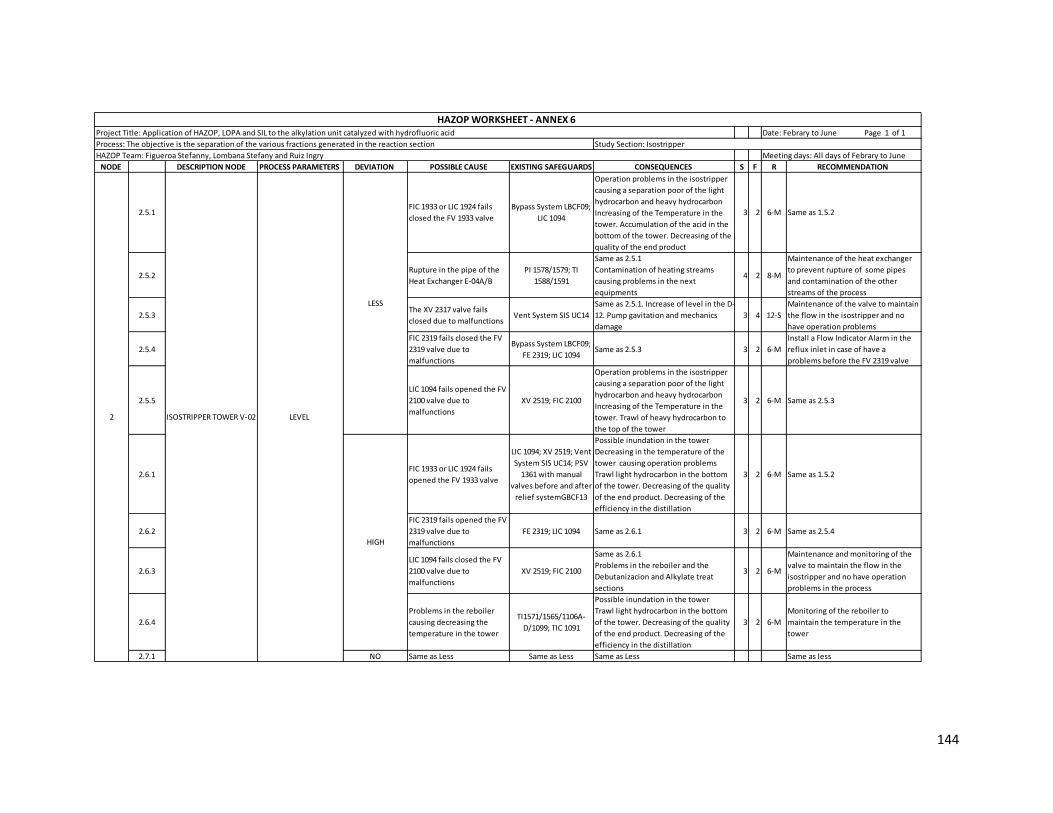
144
NODE DESCRIPTION NODE PROCESS PARAMETERS DEVIATION POSSIBLE CAUSE EXISTING SAFEGUARDS CONSEQUENCES S F R RECOMMENDATION
2.5.1FIC 1933 or LIC 1924 fails
closed the FV 1933 valve
Bypass System LBCF09;
LIC 1094
Operation problems in the isostripper
causing a separation poor of the light
hydrocarbon and heavy hydrocarbon
Increasing of the Temperature in the
tower. Accumulation of the acid in the
bottom of the tower. Decreasing of the
quality of the end product
3 2 6-M Same as 1.5.2
2.5.2Rupture in the pipe of the
Heat Exchanger E-04A/B
PI 1578/1579; TI
1588/1591
Same as 2.5.1
Contamination of heating streams
causing problems in the next
equipments
4 2 8-M
Maintenance of the heat exchanger
to prevent rupture of some pipes
and contamination of the other
streams of the process
2.5.3The XV 2317 valve fails
closed due to malfunctionsVent System SIS UC14
Same as 2.5.1. Increase of level in the D-
12. Pump gavitation and mechanics
damage
3 4 12-S
Maintenance of the valve to maintain
the flow in the isostripper and no
have operation problems
2.5.4
FIC 2319 fails closed the FV
2319 valve due to
malfunctions
Bypass System LBCF09;
FE 2319; LIC 1094Same as 2.5.3 3 2 6-M
Install a Flow Indicator Alarm in the
reflux inlet in case of have a
problems before the FV 2319 valve
2.5.5
LIC 1094 fails opened the FV
2100 valve due to
malfunctions
XV 2519; FIC 2100
Operation problems in the isostripper
causing a separation poor of the light
hydrocarbon and heavy hydrocarbon
Increasing of the Temperature in the
tower. Trawl of heavy hydrocarbon to
the top of the tower
3 2 6-M Same as 2.5.3
2.6.1FIC 1933 or LIC 1924 fails
opened the FV 1933 valve
LIC 1094; XV 2519; Vent
System SIS UC14; PSV
1361 with manual
valves before and after
relief systemGBCF13
Possible inundation in the tower
Decreasing in the temperature of the
tower causing operation problems
Trawl light hydrocarbon in the bottom
of the tower. Decreasing of the quality
of the end product. Decreasing of the
efficiency in the distillation
3 2 6-M Same as 1.5.2
2.6.2
FIC 2319 fails opened the FV
2319 valve due to
malfunctions
FE 2319; LIC 1094 Same as 2.6.1 3 2 6-M Same as 2.5.4
2.6.3
LIC 1094 fails closed the FV
2100 valve due to
malfunctions
XV 2519; FIC 2100
Same as 2.6.1
Problems in the reboiler and the
Debutanizacion and Alkylate treat
sections
3 2 6-M
Maintenance and monitoring of the
valve to maintain the flow in the
isostripper and no have operation
problems in the process
2.6.4
Problems in the reboiler
causing decreasing the
temperature in the tower
TI1571/1565/1106A-
D/1099; TIC 1091
Possible inundation in the tower
Trawl light hydrocarbon in the bottom
of the tower. Decreasing of the quality
of the end product. Decreasing of the
efficiency in the distillation
3 2 6-M
Monitoring of the reboiler to
maintain the temperature in the
tower
2.7.1 NO Same as Less Same as Less Same as Less Same as less
ISOSTRIPPER TOWER V-022
HAZOP Team: Figueroa Stefanny, Lombana Stefany and Ruiz Ingry Meeting days: All days of Febrary to June
HAZOP WORKSHEET - ANNEX 6 Project Title: Application of HAZOP, LOPA and SIL to the alkylation unit catalyzed with hydrofluoric acid Date: Febrary to June Page 1 of 1
Process: The objective is the separation of the various fractions generated in the reaction section Study Section: Isostripper
LESS
LEVEL
HIGH

145
NODE DESCRIPTION NODE PROCESS PARAMETERS DEVIATION POSSIBLE CAUSE EXISTING SAFEGUARDS CONSEQUENCES S F R RECOMMENDATION
3.1.1
Temperature of inlet
streams is cooler than
normal (<100°F) due a
problems operational in the
heat exchangers E-18 A/B
TI2316; PI 2307; PI 2305Problems of decantation causing trawl
of acid to the isostripper. Bad
separation hydrocarbon/acid
2 2 4-L
Install a Temperature indicator (TI) in
the inlet of the D-12 to control the
temperature Monitoring
of the heat exchanger to verify the
right temperature
3.1.2
Decrease in the pressure
tank due to the decreasing
of the inlet flow to the D-12
PI 2307; LIC 2311; TI
2316Same as 3.1.1 2 1 2-L
Install a Pressure Indicator in the tank
to control better the pressure of the
D-12
3.2.1
Temperature of inlet
streams is hotter than
normal (<100°F) due a
problems operational in the
heat exchangers E-18 A/B
Same as 3.1.1
Pump cavitation. Evaporation of the
hydrocarbon causing decreasing flow
of the reflux inlet in the V-02
2 2 4-L Same as 3.1.1
3.2.2
Increase in the pressure
tank due to the generation
vapor
Same as 3.1.2 Same as 3.2.1 2 1 2-L Same as 3.1.2
3.3.1 LESS
The GBCF22 Manual valve
fails opened for the factor
human
PI 2307; LBCF09 Manual
valve located after the
GBCF22 Manual valve
Decrease in the NPSH causing
cavitation in the pump P-07A/B 3 3 9-M
Feedback to employees on good
operating practices
Application of the Behaviour Based
Safety (BBS)
3.4.1
The GBCF22 Manual valve
fails closed for the factor
human
PI 2307
Overpressure in the tank. Possible
incident could causing injuries to the
employees and damage to the
equipments
3 3 9-M Same as 3.3.1
3.4.2Increase in the inlet flow
rate of the D-12
TI 1096; PI 1092B;
Controller of the exit
pipe in the top of the V-
03 TI 1625; PI2530
Trawl hydrocarbon to HF Acid
BlowDown. Trawl acid to isostripper 2 1 2-L
Periodic inspection to the inlet pipe
to maintain all the parameters in the
operational range.
3.4.3Tamponade in the
BlowDown pipe Same as 3.1.2 Same as 3.4.1 3 1 3-L
Monitoring the pipe to prevent an
incident and maintain the operation
process
3.5.1
Rupture in any heat
exchanger E-18A-F causing
release of the hydrocarbon
stream
Same as 3.1.2 Same as 3.4.1 2 3 6-MMaintenance of all heat exchangers
to keep a good operation
3.5.2LIC 2311 fails opened the LV
2311 valveFI 2315; FE 2315
Trawl of the hydrocarbon to reaction
section causing problems of operation
in this section. Increase the polymer
formation and contaminants in the
reaction section
4 2 8-M
Monitoring constantly of this
controller to avoid problems in the
reaction section and prevent the
formation of undesirables products
DEPROPANIZER FEED
SETTLER D-123
HAZOP Team: Figueroa Stefanny, Lombana Stefany and Ruiz Ingry Meeting days: All days of Febrary to June
HAZOP WORKSHEET - ANNEX 6 Project Title: Application of HAZOP, LOPA and SIL to the alkylation unit catalyzed with hydrofluoric acid Date: Febrary to June Page 1 of 1
Process: The objective is the separation of the various fractions generated in the reaction section Study Section: Isostripper
LESSLEVEL
LESS
TEMPERATURE
HIGH
PRESSURE
HIGH
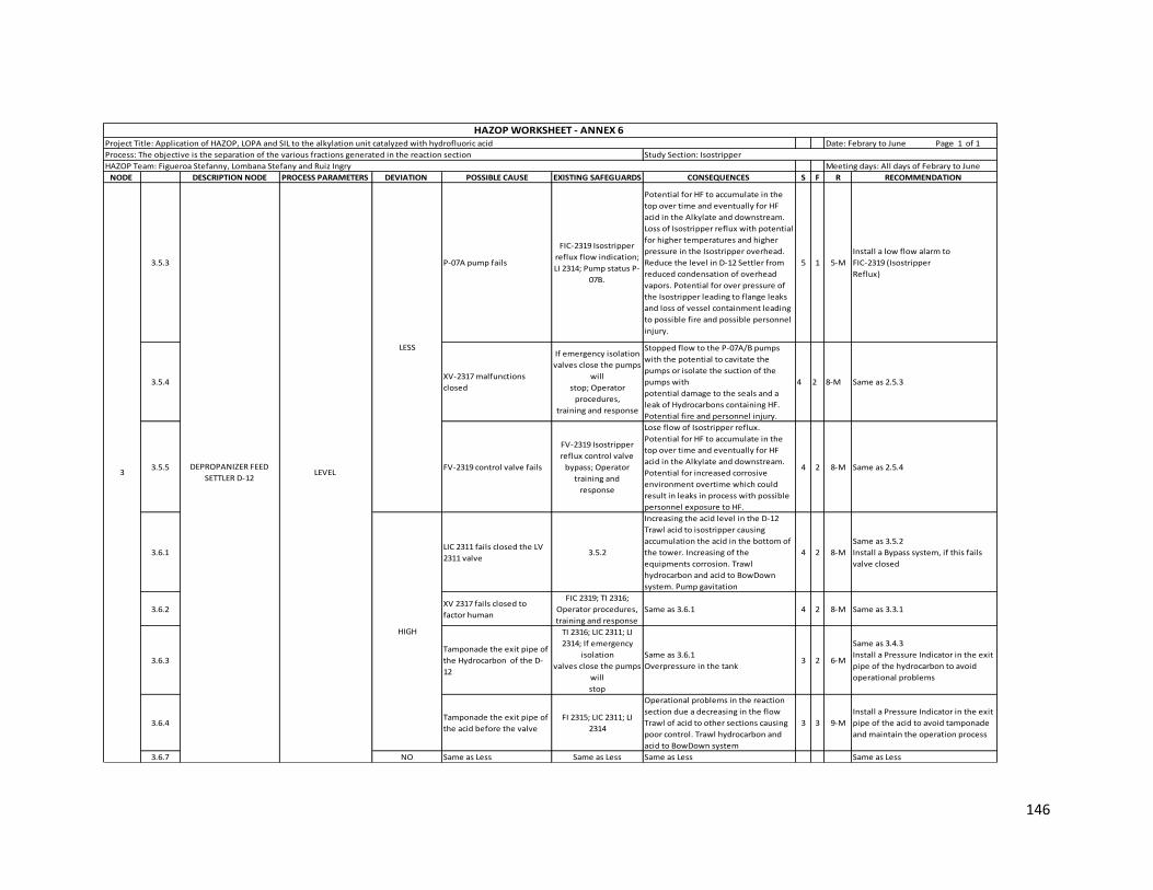
146
NODE DESCRIPTION NODE PROCESS PARAMETERS DEVIATION POSSIBLE CAUSE EXISTING SAFEGUARDS CONSEQUENCES S F R RECOMMENDATION
3.5.3 P-07A pump fails
FIC-2319 Isostripper
reflux flow indication;
LI 2314; Pump status P-
07B.
Potential for HF to accumulate in the
top over time and eventually for HF
acid in the Alkylate and downstream.
Loss of Isostripper reflux with potential
for higher temperatures and higher
pressure in the Isostripper overhead.
Reduce the level in D-12 Settler from
reduced condensation of overhead
vapors. Potential for over pressure of
the Isostripper leading to flange leaks
and loss of vessel containment leading
to possible fire and possible personnel
injury.
5 1 5-M
Install a low flow alarm to
FIC-2319 (Isostripper
Reflux)
3.5.4XV-2317 malfunctions
closed
If emergency isolation
valves close the pumps
will
stop; Operator
procedures,
training and response
Stopped flow to the P-07A/B pumps
with the potential to cavitate the
pumps or isolate the suction of the
pumps with
potential damage to the seals and a
leak of Hydrocarbons containing HF.
Potential fire and personnel injury.
4 2 8-M Same as 2.5.3
3.5.5 FV-2319 control valve fails
FV-2319 Isostripper
reflux control valve
bypass; Operator
training and
response
Lose flow of Isostripper reflux.
Potential for HF to accumulate in the
top over time and eventually for HF
acid in the Alkylate and downstream.
Potential for increased corrosive
environment overtime which could
result in leaks in process with possible
personnel exposure to HF.
4 2 8-M Same as 2.5.4
3.6.1LIC 2311 fails closed the LV
2311 valve3.5.2
Increasing the acid level in the D-12
Trawl acid to isostripper causing
accumulation the acid in the bottom of
the tower. Increasing of the
equipments corrosion. Trawl
hydrocarbon and acid to BowDown
system. Pump gavitation
4 2 8-M
Same as 3.5.2
Install a Bypass system, if this fails
valve closed
3.6.2XV 2317 fails closed to
factor human
FIC 2319; TI 2316;
Operator procedures,
training and response
Same as 3.6.1 4 2 8-M Same as 3.3.1
3.6.3
Tamponade the exit pipe of
the Hydrocarbon of the D-
12
TI 2316; LIC 2311; LI
2314; If emergency
isolation
valves close the pumps
will
stop
Same as 3.6.1
Overpressure in the tank 3 2 6-M
Same as 3.4.3
Install a Pressure Indicator in the exit
pipe of the hydrocarbon to avoid
operational problems
3.6.4Tamponade the exit pipe of
the acid before the valve
FI 2315; LIC 2311; LI
2314
Operational problems in the reaction
section due a decreasing in the flow
Trawl of acid to other sections causing
poor control. Trawl hydrocarbon and
acid to BowDown system
3 3 9-M
Install a Pressure Indicator in the exit
pipe of the acid to avoid tamponade
and maintain the operation process
3.6.7 NO Same as Less Same as Less Same as Less Same as Less
3
HAZOP Team: Figueroa Stefanny, Lombana Stefany and Ruiz Ingry Meeting days: All days of Febrary to June
HAZOP WORKSHEET - ANNEX 6 Project Title: Application of HAZOP, LOPA and SIL to the alkylation unit catalyzed with hydrofluoric acid Date: Febrary to June Page 1 of 1
Process: The objective is the separation of the various fractions generated in the reaction section Study Section: Isostripper
LESS
LEVEL
HIGH
DEPROPANIZER FEED
SETTLER D-12
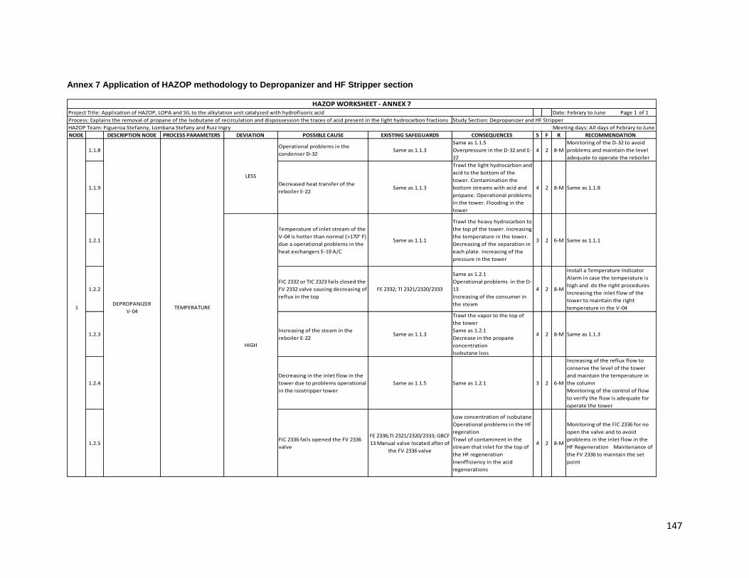
147
Annex 7 Application of HAZOP methodology to Depropanizer and HF Stripper section
NODE DESCRIPTION NODE PROCESS PARAMETERS DEVIATION POSSIBLE CAUSE EXISTING SAFEGUARDS CONSEQUENCES S F R RECOMMENDATION
1.1.8Operational problems in the
condenser D-32Same as 1.1.3
Same as 1.1.5
Overpressure in the D-32 and E-
22
4 2 8-M
Monitoring of the D-32 to avoid
problems and maintain the level
adequate to operate the reboiler
1.1.9Decreased heat transfer of the
reboiler E-22Same as 1.1.3
Trawl the light hydrocarbon and
acid to the bottom of the
tower. Contamination the
bottom streams with acid and
propane. Operational problems
in the tower. Flooding in the
tower
4 2 8-M Same as 1.1.8
1.2.1
Temperature of inlet stream of the
V-04 is hotter than normal (>170° F)
due a operational problems in the
heat exchangers E-19 A/C
Same as 1.1.1
Trawl the heavy hydrocarbon to
the top pf the tower. Increasing
the temperature in the tower.
Decreasing of the separation in
each plate. Increasing of the
pressure in the tower
3 2 6-M Same as 1.1.1
1.2.2
FIC 2332 or TIC 2323 fails closed the
FV 2332 valve causing decreasing of
reflux in the top
FE 2332; TI 2321/2320/2333
Same as 1.2.1
Operational problems in the D-
13
Increasing of the consumer in
the steam
4 2 8-M
Install a Temperature Indicator
Alarm in case the temperature is
high and do the right procedures
Increasing the inlet flow of the
tower to maintain the right
temperature in the V-04
1.2.3Increasing of the steam in the
reboiler E-22Same as 1.1.3
Trawl the vapor to the top of
the tower
Same as 1.2.1
Decrease in the propane
concentration
Isobutane loss
4 2 8-M Same as 1.1.3
1.2.4
Decreasing in the inlet flow in the
tower due to problems operational
in the isostripper tower
Same as 1.1.5 Same as 1.2.1 3 2 6-M
Increasing of the reflux flow to
conserve the level of the tower
and maintain the temperature in
the column
Monitoring of the control of flow
to verify the flow is adequate for
operate the tower
1.2.5FIC 2336 fails opened the FV 2336
valve
FE 2336;TI 2321/2320/2333; GBCF
13 Manual valve located after of
the FV 2336 valve
Low concentration of isobutane
Operational problems in the HF
regeration
Trawl of contaminent in the
stream that inlet for the top of
the HF regeneration
Inenfficiency in the acid
regenerations
4 2 8-M
Monitoring of the FIC 2336 for no
open the valve and to avoid
problems in the inlet flow in the
HF Regeneration Maintenance of
the FV 2336 to maintain the set
point
TEMPERATUREDEPROPANIZER
V-041
LESS
HIGH
HAZOP WORKSHEET - ANNEX 7Project Title: Application of HAZOP, LOPA and SIL to the alkylation unit catalyzed with hydrofluoric acid Date: Febrary to June Page 1 of 1
Process: Explains the removal of propane of the Isobutane of recirculation and dispossession the traces of acid present in the light hydrocarbon fractions Study Section: Depropanizer and HF Stripper
HAZOP Team: Figueroa Stefanny, Lombana Stefany and Ruiz Ingry Meeting days: All days of Febrary to June

148
NODE DESCRIPTION NODE PROCESS PARAMETERS DEVIATION POSSIBLE CAUSE EXISTING SAFEGUARDS CONSEQUENCES S F R RECOMMENDATION
1.2.6 XV 2492 fails opened Same as 1.1.7
Decreasin the level in te tower
Same as 1.2.1
Operational problems in the
reaction and ALKAD sections
4 2 8-M
Maintenance of the valve to avoid
decreasing the level in the tower
and prevent the operational
problems. Install a Flow Indicator
after the XV 2492 to verify the flow
of inlet of the next sections
1.2.7Increased heat transfer of the
reboiler E-22Same as 1.1.3 Same as 1.2.3 4 2 8-M
Monitoring and maintenance of
the reboiler and verify the inlet
stream of the steam is right
1.2.8
Rupture in the inlet pipe of the
tower due to the corrosion or
overpressure
PI 2365
Possible fire explosion
Air pollution
Injuries to the employees
Equipment damage
Economic losses
Stop in the unit
5 2 10-M
Maintenance of the pipe to avoid
an incident and maintain the
operation of the unit
Install a control loop that work
with a Pressure Indicator which
closes a valve in case of the
rupture of the pipe
1.2.9
Rupture in the reflux pipe of the V-
04 due to the corrosion or
overpressure
FIC 2332; TI 2321/2320/2333 Same as 1.2.8 5 2 10-M Same as 1.2.8
1.2.10
Rupture in the exit pipe of the
tower due to the overpressure or
corrosion
TI 2334; PI 2490; XV 2492 Same as 1.2.8 5 2 10-M Same as 1.2.8
1.3.1 PSV 2327 fails opened
GBCF 14 Manual valve located
before of the PSV 2327; LO
Manual valve located after of
the PSV 2327
Operational problems in the
Tea system due to increased of
the inlet flow
Increasing of the vaporization
causing trawl the heavy
hydrocarbon to the top of the
tower
3 2 6-M
Monitoring of the PSV 2327 to
avoid less pressure in the tower
and prevent the decreasing of the
isobutane
1.3.2Decreasing of the inlet flow of the
tower Same as 1.1.5 Same as 1.2.1 3 2 6-M
Monitoring of the Flow Indicator
Control to verify the flow is the
right for the operation of the tower
1.3.3 Break in the inlet pipe of the tower Same as 1.2.8
Possible fire explosion
Air pollution
Injuries to the employees
Equipment damage
Economic losses
Stop of the unit
5 2 10-M Same as 1.2.8
1.3.4 Break in the exit pipe of the tower TI2334; FIC 2337; LIC 2334Same as 1.3.3
Stop of the unit 5 2 10-M Same as 1.2.8
DEPROPANIZER
V-041
HIGHTEMPERATURE
PRESSURE
HAZOP WORKSHEET - ANNEX 7Project Title: Application of HAZOP, LOPA and SIL to the alkylation unit catalyzed with hydrofluoric acid Date: Febrary to June Page 1 of 1
Process: Explains the removal of propane of the Isobutane of recirculation and dispossession the traces of acid present in the light hydrocarbon fractions Study Section: Depropanizer and HF Stripper
HAZOP Team: Figueroa Stefanny, Lombana Stefany and Ruiz Ingry Meeting days: All days of Febrary to June
LESS

149
NODE DESCRIPTION NODE PROCESS PARAMETERS DEVIATION POSSIBLE CAUSE EXISTING SAFEGUARDS CONSEQUENCES S F R RECOMMENDATION
1.4.1 PSV 2327 fails closed
GBCF 13 Manual valve located
before of the PSV 2327; LBCF 05
Manula valve located after of
the GBCF 13 Manual valve
Overpressure in the tower
Decreasing of the vaporization
causing higher concentration of
the light hydrocarbon in the
tower
3 2 6-M
Monitoring of the PSV 2327 to
avoid high pressure in the tower
and prevent the trawl of the
propane and acid in the isobutane
stream
1.4.2Increasing of the inlet flow of the
tower Same as 1.1.5
Flooding in the tower
Same as 1.4.1
Decrease in the removal of
propane Increasing
of concentration of the
contaminant in the isobutane
stripping stream
4 2 8-M Same as 1.1.5
1.4.3
Tamponade in the inlet pipe of the
tower due to the accumulation of
the contaminants
Same as 1.2.8
Same as 1.4.1
Operational problems in the
isostripper due to that comes
back the flow to the V-02
4 2 8-M Same as 1.2.8
1.4.4
Tamponade in the exit pipe of the
tower due to the accumulation of
the contaminants
Same as 1.3.4
Same as 1.4.1
Operational problems in the
reaction and ALKAD sections
4 2 8-M Same as 1.2.8
1.4.5
Tamponade of the lateral pipe of
the tower due to the accumulation
of the contaminants
FIC 2336; FE 2326; LIC 2324; TI
2321
Same as 1.4.1
Operational problems in the HF
regeneration due to the less
flow
4 1 4-L Same as 1.2.8
1.5.1Increasing the condensate flow of
the D-32LIC 2488; FIC 2328
Increasing heat transfer in the E-
22 causing a high vaporization
Trawl of isobutane to the top of
the tower
Possible increased of the
pressure in the V-04
Unnecessary use of steam
3 1 3-L
Install a Flow Indicator Alarm in the
pipe of condensate in case of high
flow the operator apply the good
practices to control the flow
Monitoring of the FIC 2328 for that
no fails the signal to the valve
1.5.2 Decreasing of the level in the D-32 LIC 2488
Increasing heat transfer in the E-
22 causing a high vaporization
Unnecessary use of steam
trawl of steam to the head
condensate
2 2 4-L
Install an Alarm in case the level is
less or high to avoid operational
problems in the D-32, E-22 and in
the tower
1.5.3 XV 2492 fails opened Same as 1.1.7
Bad separation in the
depropanizer tower
Same as 1.2.1
Operational problems in the
reaction and ALKAD sections
3 2 6-M Same as 1.2.6
PRESSURE
LESSLEVEL
DEPROPANIZER
V-041
HAZOP WORKSHEET - ANNEX 7Project Title: Application of HAZOP, LOPA and SIL to the alkylation unit catalyzed with hydrofluoric acid Date: Febrary to June Page 1 of 1
Process: Explains the removal of propane of the Isobutane of recirculation and dispossession the traces of acid present in the light hydrocarbon fractions Study Section: Depropanizer and HF Stripper
HAZOP Team: Figueroa Stefanny, Lombana Stefany and Ruiz Ingry Meeting days: All days of Febrary to June
HIGH
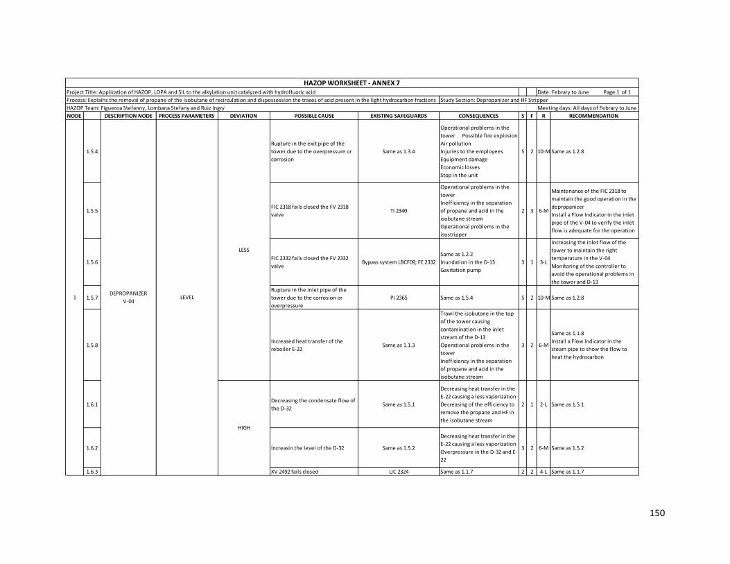
150
NODE DESCRIPTION NODE PROCESS PARAMETERS DEVIATION POSSIBLE CAUSE EXISTING SAFEGUARDS CONSEQUENCES S F R RECOMMENDATION
1.5.4
Rupture in the exit pipe of the
tower due to the overpressure or
corrosion
Same as 1.3.4
Operational problems in the
tower Possible fire explosion
Air pollution
Injuries to the employees
Equipment damage
Economic losses
Stop in the unit
5 2 10-M Same as 1.2.8
1.5.5FIC 2318 fails closed the FV 2318
valveTI 2340
Operational problems in the
tower
Inefficiency in the separation
of propane and acid in the
isobutane stream
Operational problems in the
isostripper
2 3 6-M
Maintenance of the FIC 2318 to
maintain the good operation in the
depropanizer
Install a Flow Indicator in the inlet
pipe of the V-04 to verify the inlet
flow is adequate for the operation
1.5.6FIC 2332 fails closed the FV 2332
valveBypass system LBCF09; FE 2332
Same as 1.2.2
Inundation in the D-13
Gavitation pump
3 1 3-L
Increasing the inlet flow of the
tower to maintain the right
temperature in the V-04
Monitoring of the controller to
avoid the operational problems in
the tower and D-13
1.5.7
Rupture in the inlet pipe of the
tower due to the corrosion or
overpressure
PI 2365 Same as 1.5.4 5 2 10-M Same as 1.2.8
1.5.8Increased heat transfer of the
reboiler E-22Same as 1.1.3
Trawl the isobutane in the top
of the tower causing
contamination in the inlet
stream of the D-13
Operational problems in the
tower
Inefficiency in the separation
of propane and acid in the
isobutane stream
3 2 6-M
Same as 1.1.8
Install a Flow Indicator in the
steam pipe to show the flow to
heat the hydrocarbon
1.6.1Decreasing the condensate flow of
the D-32Same as 1.5.1
Decreasing heat transfer in the
E-22 causing a less vaporization
Decreasing of the efficiency to
remove the propane and HF in
the isobutane stream
2 1 2-L Same as 1.5.1
1.6.2 Increasin the level of the D-32 Same as 1.5.2
Decreasing heat transfer in the
E-22 causing a less vaporization
Overpressure in the D-32 and E-
22
3 2 6-M Same as 1.5.2
1.6.3 XV 2492 fails closed LIC 2324 Same as 1.1.7 2 2 4-L Same as 1.1.7
LEVEL
LESS
HIGH
DEPROPANIZER
V-041
HAZOP WORKSHEET - ANNEX 7Project Title: Application of HAZOP, LOPA and SIL to the alkylation unit catalyzed with hydrofluoric acid Date: Febrary to June Page 1 of 1
Process: Explains the removal of propane of the Isobutane of recirculation and dispossession the traces of acid present in the light hydrocarbon fractions Study Section: Depropanizer and HF Stripper
HAZOP Team: Figueroa Stefanny, Lombana Stefany and Ruiz Ingry Meeting days: All days of Febrary to June

151
NODE DESCRIPTION NODE PROCESS PARAMETERS DEVIATION POSSIBLE CAUSE EXISTING SAFEGUARDS CONSEQUENCES S F R RECOMMENDATION
1.6.4FIC 2318 fails opened the FV 2318
valveSame as 1.5.5
Decreasing the temperature in
the tower causing bad
separation
Operational problems in the
isostripper sections
Flooding in the tower
3 3 9-M Same as 1.5.5
1.6.5FIC 2332 fails opened the FV 2332
valve
GBCF 22 Manual valve located
after of the FV 2332 valve; LIC
2324; TI 2320/2333/2321
Operational problems in the HF
stripper and D-13
Possible presence of acid in the
Flushing system
Increasing the concentration of
propane and acid of the bottom
in the tower
3 2 6-M
Decreasing the inlet flow of the
tower to maintain the right
temperature in the V-04
Monitoring of the controller to
avoid the operational problems in
the tower, D-13 and reaction
section
1.6.6
Tamponade in the exit pipe of the
tower due to the accumulation of
the contaminants
Same as 1.3.4 Same as 1.4.4 4 2 8-M Same as 1.2.8
1.6.7Decreased heat transfer of the
reboiler E-22Same as 1.1.3 Same as 1.1.9 4 2 8-M Same as 1.1.8
1.6.8
Tamponade of the lateral pipe of
the tower due to the accumulation
of the contaminants
Same 1.4.5 Same as 1.4.5 4 1 4-L Same as 1.2.8
1.7.1 NO Same as Less Same as Less Same as Less Same as Less
2.1.1Increasing of the cooling water in
the E-21 A/BTI 2353
Decrease of the separation
time between of propane and
acid
Contamination of the stream
that come to the reaction
section causing problems
operational
3 3 9-M
Constantly monitoring to the
cooling water to avoid problems in
the E-21A/B
2.1.2
Rupture in the inlet line of the
cooling water due to the
overpressure
PI 2359; TI 2353
Injuries to the employees
Equipment damage
Economic losses
Stop in the unit
3 2 6-M
Maintenance of the line to avoid
an incident in the unit or stop or
the unit. Install a Flow Indicator in
the inlet pipe to show the flow is
the necessary to condensate the
inlet stream
2.1.3
Tamponade in the pipes of the
heat exchanger E-21A/B due to the
poor maintenance
TI 2353; TI 2359
Decrease of the surface area
Break or leak in the pipes for
overpressure causing
contamination of the stream
Operational problems in the D-
13, V-04 and V-05 causing less
efficiency in the process
4 2 8-M
Implement a differential pressure
gauge to work with the input and
output currents for the steam side
Constantly maintenance of the
heat exchanger to maintain
adequate operations in the process
2.1.4Decreasing the flow in the inlet of
the heat exchanger E-21 A/BFIC 2318; TI 2362; TI 2340
Decreasing the temperature of
the inlet stream of the D-13
Same as 2.1.1
3 3 9-M
Install a Flow Indicator Control to
work in loop with an Flow Indicator
in the cooling pipe to maintain the
temperature the inlet stream of
the D-13
LEVELDEPROPANIZER
V-041
TEMPERATUREDEPROPANIZER
RECEIVER D-132
HIGH
LESS
HAZOP WORKSHEET - ANNEX 7Project Title: Application of HAZOP, LOPA and SIL to the alkylation unit catalyzed with hydrofluoric acid Date: Febrary to June Page 1 of 1
Process: Explains the removal of propane of the Isobutane of recirculation and dispossession the traces of acid present in the light hydrocarbon fractions Study Section: Depropanizer and HF Stripper
HAZOP Team: Figueroa Stefanny, Lombana Stefany and Ruiz Ingry Meeting days: All days of Febrary to June

152
NODE DESCRIPTION NODE PROCESS PARAMETERS DEVIATION POSSIBLE CAUSE EXISTING SAFEGUARDS CONSEQUENCES S F R RECOMMENDATION
2.2.1Decreasing of the cooling water in
the E-21 A/BSame as 2.1.1
Bad separation of the propane
and acid in the D-13
Increasing the vapor in the D-13
causing high pressure
Operational problems in the
next section due to the high
temperature of the stream
3 3 9-M Same as 2.1.1
2.2.2Tamponade in the inlet line of the
cooling water Same as 2.1.2
Decreasing of the heat transfer
in the heat exchanger due that
the cooling pipe is blocked
Increasing the vapor in the D-
13, sending the vapor to the
depropanizer and the reaction
section causing operational
problems decreasing the
efficiency the process
3 2 6-M
Same as 2.1.2
Install a Pressure Indicator in the
inlet pipe of the cooling water to
avoid problems in the process
2.2.3Increasing the flow in the inlet of
the heat exchanger E-21 A/BSame as 2.1.4
Same as 2.2.1
Bad condensation of the vapor
stream
3 3 9-M Same as 2.1.4
2.3.1PIC 2350 fails opened the PV 2350
valve PI 2547/2357
Decrease in the NPSH causing
cavitation in the pump P-08A/B
Operational problems in the D-
13
2 1 2-L
Maintenance of the controller and
valve to avoid the propane steam
come back to the V-04
2.3.2
Decreasing the inlet flow in the D-1
due to the operationla problems in
the V-04 or V-05
PI 2351; PIC 2350; PI 2547; TI 2359 Same as 2.3.1 2 2 4-L
Install a Flow Indicator in each inlet
pipe of the D-13 to control the
operations in this tank
2.4.1PIC 2350 fails closed the PV 2350
valve
PI 2547/2357; Bypass system
LBCF09
Overpressure in the tank
Decreasing the liquid in the
tank causing trawl of vapor in
the next sections
Mechanic damage in the pump
P-08A/B
3 2 6-M
Monitoring of the controller and
valve to avoid operational
problems in the tank
2.4.2
Tamponade in the BlowDown pipe
due to the accumulation of
contaminants
PI2537
Overpressure in the tank
causing possible explosion
Contamination of the stream
due to the mixed of the acid in
the propane stream
4 2 8-M
Maintenance of the pipe to
prevent an incident in case of an
overpressure in the pipe causing a
rupture
2.4.3
Increasing the inlet flow in the D-
13 due to the operationla
problems in the V-04 or V-05
Same as 2.3.2
Overpressure in the tank
causing possible explosion
Mechanic damage in the pump
P-08A/B
3 2 6-M Same as 2.3.2
TEMPERATURE
DEPROPANIZER
RECEIVER D-132
HIGH
LESS
HIGH
HAZOP WORKSHEET - ANNEX 7Project Title: Application of HAZOP, LOPA and SIL to the alkylation unit catalyzed with hydrofluoric acid Date: Febrary to June Page 1 of 1
Process: Explains the removal of propane of the Isobutane of recirculation and dispossession the traces of acid present in the light hydrocarbon fractions Study Section: Depropanizer and HF Stripper
HAZOP Team: Figueroa Stefanny, Lombana Stefany and Ruiz Ingry Meeting days: All days of Febrary to June
PRESSURE

153
NODE DESCRIPTION NODE PROCESS PARAMETERS DEVIATION POSSIBLE CAUSE EXISTING SAFEGUARDS CONSEQUENCES S F R RECOMMENDATION
2.5.1PIC 2350 fail closed the PV 2350
valveBypass system, PI 2547
Mechanic damage of the pump
and cavitation
Operational problems in the V-
04 and V-05 towers
Trawl of propane to the
reaction section
2 1 2-L
Review constantly of the controller
to avoid bad signal to the control
room and valve
2.5.2Decreasing of the temperature in
the V-04 tower causing less vapor TI 2320/ 2321 / 2333
Mechanic damage of the pump
P-08A/B and cavitation
Decreasing of the reflux
causing high temperature in
the top of the tower
Inefficiency of the separation
in the depropanizer
Flooding in the V-04 tower
Operational problems in the V-
05 tower
Unnecessary use of cooling
water
3 1 3-L
Control of the process in the
depropanizer to avoid a decreasing
in the temperature and prevents
possible damage in the next
equipments
2.5.3Rupture in the inlet pipe of the D-
13 due to the overpressure PI 2547; TI 2359
Possible fire explosion
Air pollution
Injuries to the employees
Equipment damage
Economic losses
Stop of the unit
5 2 10-M Same as 1.2.8
2.5.4Decreasing the cooling water
causing less condensation TI 2353 / 2359
Overpressure in the D-13
Increasing of hydrocarbon
vapor inside the tank, causing
trawl of the vapor to the
depropanizer, HF stripper and
reaction section
Mechanic damage of the pump
P-08A/B and cavitation
3 2 6-M
Monitoring of the cooling system
to prevent problem in the
operational process
Install a Flow indicator to work in a
loop with the Temperature
indicator in the inlet of the first
heat exchanger to maintain the
temperature in the D-13
2.5.5LIC 2355 fails opened the LV 2335
valve LIC 2358
Trawl of the hydrocarbon to the
reaction section causing
operational problems and less
production of alkylate
4 2 8-M Same as 2.5.1
2.5.6
LIC 2358 fail send a bad signal to
the control room and produce
opening the FV 1145 valveLIC 2355
Trawl of hydrocarbon to the HF
stripper causing bad separation
and high formation of the
polymer and contaminant
4 2 8-M Same as 2.5.1
2.5.7Rupture in the acid pipe due to the
corrosion LIC 2355; LIC 2358
High air pollution
Injuries to the employees
Equipment damage
Economic losses
Stop of the unit
5 2 10-M
Maintenance constantly of the
pipe to avoid an catastrophic
incident in the plant and prevent
injuries to the nearest town of the
plant
2.5.8Rupture in the propane pipe due to
the overpressure or corrosion XV 2335; FIC 2332 Same as 2.5.3 5 2 10-M Same as 1.2.8
LEVEL DEPROPANIZER
RECEIVER D-132 LESS
HAZOP WORKSHEET - ANNEX 7Project Title: Application of HAZOP, LOPA and SIL to the alkylation unit catalyzed with hydrofluoric acid Date: Febrary to June Page 1 of 1
Process: Explains the removal of propane of the Isobutane of recirculation and dispossession the traces of acid present in the light hydrocarbon fractions Study Section: Depropanizer and HF Stripper
HAZOP Team: Figueroa Stefanny, Lombana Stefany and Ruiz Ingry Meeting days: All days of Febrary to June

154
NODE DESCRIPTION NODE PROCESS PARAMETERS DEVIATION POSSIBLE CAUSE EXISTING SAFEGUARDS CONSEQUENCES S F R RECOMMENDATION
2.6.1PIC 2350 fail opened the PV 2350
valvePI 2547
Possible overpressure in the D-
13 and V-04
Trawl of the liquid to the HF
acid BlowDown
Possible trawl of acid to the
depropanizer and HF srtipper
Increasing of the corrosion in
the line and equipments
4 2 8-M Same as 2.5.1
2.6.2Increasing of the temperature in
the V-04 causing high vapor Same as 2.5.2 Same as 2.6.1 4 1 4-L
Control of the temperature of the
process in the depropanizer to
avoid possible damage in the next
equipments and operational
problems
2.6.3LIC 2355 fails closed the LV 2335
valve same as 2.5.5
Same as 2.6.1
Operational problems in the
reaction section
4 2 8-M Same as 2.5.1
2.6.4Increasing the cooling water
causing high condensation same as 2.5.4
Increasing in the presence of
propane and HF in the bottom
of the isobutane stream
Possible presence of the acid in
the flushing system
Increasing of the reflux causing
decreasing in the temperature
in the tower
Flooding in the V-04 tower
3 2 6-M Same as 2.5.4
2.6.5
LIC 2358 fail send a bad signal to
the control room and produce
closing the FV 1145 valve
Same as 2.5.6
Operational problems in the HF
stripper
Same as 2.6.4
Cavitation in the pumps P-
08A/B
4 2 8-M Same as 2.5.1
2.6.7Increasing of the stream from to
the top of HF stripperFI 1148; TI 1149 Same as 2.6.1 4 2 8-M
Control of the process in the HF
stripper to avoid operational
problems in the V-04 and D-13
2.7.1 NO Same as Less Same as Less Same as Less Same as Less
3.1.1 TEMPERATUREConsidered but nothing significant
identified
3.2.1 LESSDecreasing of the suspended solids
in the filter PDI 2345
It does not represent any
damage1 1 1-L
Constantly monitoring of the filter
to maintain the operation
3.3.1 HIGHIncreasing of the suspended solids
in the filter Same as 3.2.1
Possible presence of acid in the
flushing system
Increasing of contaminant in
the isobutane stream
2 1 2-L
Constantly monitoring of the
process in the V-04 tower to avoid
that the isobutane stream come
with contaminant
3.4.1 LEVELConsidered but nothing significant
identified
LEVEL DEPROPANIZER
RECEIVER D-132
HIGH
HAZOP WORKSHEET - ANNEX 7Project Title: Application of HAZOP, LOPA and SIL to the alkylation unit catalyzed with hydrofluoric acid Date: Febrary to June Page 1 of 1
Process: Explains the removal of propane of the Isobutane of recirculation and dispossession the traces of acid present in the light hydrocarbon fractions Study Section: Depropanizer and HF Stripper
HAZOP Team: Figueroa Stefanny, Lombana Stefany and Ruiz Ingry Meeting days: All days of Febrary to June
3ISOBUTANE FLUSH
FILTER S-04A/BPRESSURE

155
NODE DESCRIPTION NODE PROCESS PARAMETERS DEVIATION POSSIBLE CAUSE EXISTING SAFEGUARDS CONSEQUENCES S F R RECOMMENDATION
4.1.1Temperature of inlet stream of the
V-05 is cooler than normal TI 1582
Decreasing of the efficiency of
the separation
Possible presence of acid in the
propane stream
Corrosion of the next
equipments
4 2 8-M
Monitoring of the process in the
depropanizer to maintain the good
operation in the V-05
Install a Temperature Indicator in
the inlet of the tower to show the
right temperature of the inlet
stream
4.1.2FIC 1145 or LIC 2358 fails opened
the FV 2332 valve FE 1145
Trawl of acid in the porpane
stream. Flooding in the tower
Corrosion of the next
equipments
3 2 6-M
Increasing of the steam in the
reboiler to maintain of the
operating temperature in the
tower
Same as 2.5.1
4.1.3Fail or rupture in the E-22 causing
less temperature in the towerFIC 1520; TI 1582
Contamination of the stream
inside the tower
Stop of the unit
contamination in the vapor
stream
3 1 3-LMaintenance of the reboiler to
prevent rupture of the pipes
4.1.4Decreasing of the steam in the
reboiler E-23TI 2526; PI 2525
Increasing the level in the V-05
tower. Flooding in the tower
Same as 4.1.1
4 2 8-M Same as 1.1.3
4.1.5Operational problems in the
condenser D-32LIC 1522; PI 2529
Decreasing of the separation
Inefficiency in the process of
the tower
Operational problem in the
reboiler
2 1 2-L
Maintenance constant to the
condenser to avoid problem in the
reboiler E-23
4.1.6Decreased heat transfer of the
reboiler E-23PI 2525; TI 2526
Flooding in the V-05 tower
Bad separation of the HF acid
Contamination of the propane
stream with acid
3 1 3-L
Monitoring of the D-33 to avoid
problems and maintain the level
adequate to operate the reboiler E-
23
4.2.1Temperature of inlet stream of the
V-05 is hotter than normal Same as 4.1.1
Unncessary use of the steam
Trawl of propane to the top of
the tower causing operational
problems in the V-04 and D-13
Contamination of the vapor
stream
3 2 6-M Same as 4.1.1
4.2.2FIC 1145 or LIC 2358 fails closed the
FV 2332 valve
Bypass system LBCF09 located in
the inlet pipe of the V-05; FE
1145
Operational problems in the V-
04 and D-13 due to increasing of
the flow
Decreasing of the propane
stream to the exit of the V-05
tower Trawl of
propane to the top of the tower
3 1 3-L Same as 2.5.1
TEMPERATUREHF STRIPPER V-054
HIGH
HAZOP WORKSHEET - ANNEX 7Project Title: Application of HAZOP, LOPA and SIL to the alkylation unit catalyzed with hydrofluoric acid Date: Febrary to June Page 1 of 1
Process: Explains the removal of propane of the Isobutane of recirculation and dispossession the traces of acid present in the light hydrocarbon fractions Study Section: Depropanizer and HF Stripper
HAZOP Team: Figueroa Stefanny, Lombana Stefany and Ruiz Ingry Meeting days: All days of Febrary to June
LESS
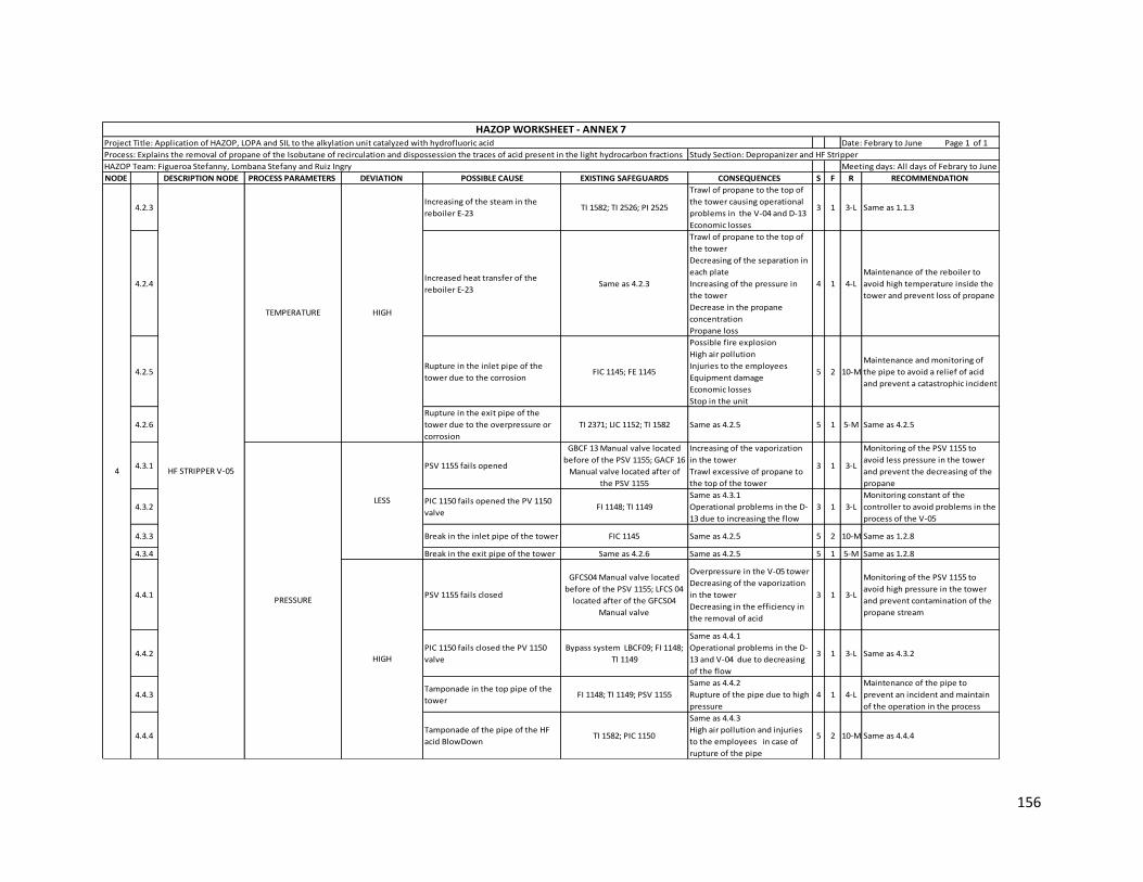
156
NODE DESCRIPTION NODE PROCESS PARAMETERS DEVIATION POSSIBLE CAUSE EXISTING SAFEGUARDS CONSEQUENCES S F R RECOMMENDATION
4.2.3Increasing of the steam in the
reboiler E-23TI 1582; TI 2526; PI 2525
Trawl of propane to the top of
the tower causing operational
problems in the V-04 and D-13
Economic losses
3 1 3-L Same as 1.1.3
4.2.4Increased heat transfer of the
reboiler E-23Same as 4.2.3
Trawl of propane to the top of
the tower
Decreasing of the separation in
each plate
Increasing of the pressure in
the tower
Decrease in the propane
concentration
Propane loss
4 1 4-L
Maintenance of the reboiler to
avoid high temperature inside the
tower and prevent loss of propane
4.2.5Rupture in the inlet pipe of the
tower due to the corrosion FIC 1145; FE 1145
Possible fire explosion
High air pollution
Injuries to the employees
Equipment damage
Economic losses
Stop in the unit
5 2 10-M
Maintenance and monitoring of
the pipe to avoid a relief of acid
and prevent a catastrophic incident
4.2.6
Rupture in the exit pipe of the
tower due to the overpressure or
corrosion
TI 2371; LIC 1152; TI 1582 Same as 4.2.5 5 1 5-M Same as 4.2.5
4.3.1 PSV 1155 fails opened
GBCF 13 Manual valve located
before of the PSV 1155; GACF 16
Manual valve located after of
the PSV 1155
Increasing of the vaporization
in the tower
Trawl excessive of propane to
the top of the tower
3 1 3-L
Monitoring of the PSV 1155 to
avoid less pressure in the tower
and prevent the decreasing of the
propane
4.3.2PIC 1150 fails opened the PV 1150
valveFI 1148; TI 1149
Same as 4.3.1
Operational problems in the D-
13 due to increasing the flow
3 1 3-L
Monitoring constant of the
controller to avoid problems in the
process of the V-05
4.3.3 Break in the inlet pipe of the tower FIC 1145 Same as 4.2.5 5 2 10-M Same as 1.2.8
4.3.4 Break in the exit pipe of the tower Same as 4.2.6 Same as 4.2.5 5 1 5-M Same as 1.2.8
4.4.1 PSV 1155 fails closed
GFCS04 Manual valve located
before of the PSV 1155; LFCS 04
located after of the GFCS04
Manual valve
Overpressure in the V-05 tower
Decreasing of the vaporization
in the tower
Decreasing in the efficiency in
the removal of acid
3 1 3-L
Monitoring of the PSV 1155 to
avoid high pressure in the tower
and prevent contamination of the
propane stream
4.4.2PIC 1150 fails closed the PV 1150
valve
Bypass system LBCF09; FI 1148;
TI 1149
Same as 4.4.1
Operational problems in the D-
13 and V-04 due to decreasing
of the flow
3 1 3-L Same as 4.3.2
4.4.3Tamponade in the top pipe of the
tower FI 1148; TI 1149; PSV 1155
Same as 4.4.2
Rupture of the pipe due to high
pressure
4 1 4-L
Maintenance of the pipe to
prevent an incident and maintain
of the operation in the process
4.4.4Tamponade of the pipe of the HF
acid BlowDown TI 1582; PIC 1150
Same as 4.4.3
High air pollution and injuries
to the employees in case of
rupture of the pipe
5 2 10-M Same as 4.4.4
TEMPERATURE
HF STRIPPER V-054
HIGH
HAZOP WORKSHEET - ANNEX 7Project Title: Application of HAZOP, LOPA and SIL to the alkylation unit catalyzed with hydrofluoric acid Date: Febrary to June Page 1 of 1
Process: Explains the removal of propane of the Isobutane of recirculation and dispossession the traces of acid present in the light hydrocarbon fractions Study Section: Depropanizer and HF Stripper
HAZOP Team: Figueroa Stefanny, Lombana Stefany and Ruiz Ingry Meeting days: All days of Febrary to June
LESS
HIGH
PRESSURE

157
NODE DESCRIPTION NODE PROCESS PARAMETERS DEVIATION POSSIBLE CAUSE EXISTING SAFEGUARDS CONSEQUENCES S F R RECOMMENDATION
4.5.1
Increased heat transfer of the
reboiler due to increasing the
steam flow
PI 2525; TI 2526
Increasing of the pressure in
the tower
Unnecessary use of steam
Increasing the vapor inside in
the tower causing a decreasing
of the level
3 1 3-L Same as 4.2.4
4.5.2FIC 1145 fails closed the FV 1145
valve LIC 1152; Baypass system LBCF09
Operational problems in the
tower Bad operation
in the reboiler
Increasing of the temperature
and overpressure in the V-05
3 1 3-LReview constantly the controller to
prevent falls in the process
4.5.3Increasing the condensate flow of
the D-33LIC 1522; FIC 1520
Increasing heat transfer in the E-
23 causing a high vaporization
Trawl of propane to the top of
the tower
Decreasing the propane stream
Possible increased of the
pressure in the V-05
Unnecessary use of steam
3 2 6-M
Install a Flow Indicator Alarm in the
pipe of condensate in case of high
flow the operator apply the good
practices to control the flow
Monitoring of the LIC 1522 and FIC
1520 for that no fails the signal to
the valve
4.5.4 Decreasing of the level in the D-33 LIC 1522
Increasing heat transfer in the E-
23 causing a high vaporization
Unnecessary use of steam
trawl of steam to the head
condensate
3 2 6-M
Install an Alarm in case the level is
less or high to avoid operational
problems in the D-33, E-23 and in
the v-05 tower
4.5.5Rupture in the exit pipe of the V-05
towerSame as 4.2.6
Possible fire explosion
High air pollution
Injuries to the employees
Equipment damage
Economic losses
Stop in the unit
5 1 5-M
Maintenance constant to the pipe
to avoid rupture due to the
corrosion or overpressure in the
pipe
4.5.6Rupture in the inlet pipe of the V-
05 tower Same as 4.3.3 Same as 4.5.5 5 2 10-M Same as 4.5.5
4.6.1
Decreasing heat transfer of the
reboiler due to decreasing the
steam flow
Same as 4.5.1
Decreasing of the vaporization
causing bad separation of the
acid Flooding
in the V-05 tower
Possible presence of acid in the
propane stream
3 1 3-L
Install a Flow Indicator in the
steam pipe to show the flow for
the good operation
4.6.2FIC 1145 fails opened the FV 1145
valve FE 1145 Same as 4.6.1 3 2 6-M Same as 4.5.2
LEVELHF STRIPPER V-054
HIGH
HAZOP WORKSHEET - ANNEX 7Project Title: Application of HAZOP, LOPA and SIL to the alkylation unit catalyzed with hydrofluoric acid Date: Febrary to June Page 1 of 1
Process: Explains the removal of propane of the Isobutane of recirculation and dispossession the traces of acid present in the light hydrocarbon fractions Study Section: Depropanizer and HF Stripper
HAZOP Team: Figueroa Stefanny, Lombana Stefany and Ruiz Ingry Meeting days: All days of Febrary to June
LESS

158
NODE DESCRIPTION NODE PROCESS PARAMETERS DEVIATION POSSIBLE CAUSE EXISTING SAFEGUARDS CONSEQUENCES S F R RECOMMENDATION
4.6.3Decreasing the condensate flow of
the D-33Same as 4.5.3
Decreasing heat transfer in the
E-23 causing a less vaporization
Flooding in the V-05 tower
Possible presence of acid in the
propane stream
3 2 6-M
Install a Flow Indicator Alarm in the
pipe of condensate in case of less
flow the operator apply the good
practices to control the operation
4.6.4 Increasing of the level in the D-33 Same as 4.5.4
Decreasing heat transfer in the
E-23 causing a less vaporization
Overpressure in the D-33 and E-
23
2 2 4-L Same as 4.5.4
4.6.5Tamponade in the exit pipe of the
V-05 towerTI 2371
Operational problems in the
treatment of propane and
reaction section
Trawl of propane to the top of
the tower
3 3 9-M
Maintenance of the pipe to avoid
problems in the V-05 and the next
section
4.6.6PIC 1150 fails closed the PV 1150
valveSame as 4.4.2
Overpressure in the V-05 tower
Trawl of the vapor to the inlet
pipe causing operational
problems in the depropanizer
and D-13
3 1 3-L Same as 4.3.2
LIC 1152 fails closed the LV 1152
valveBypass system LWCS07
Operational problems in the
treatment propane
Increasing the flow to the
propane flush filters
2 1 2-L
Maintenance of the controller to
prevent operational problems in
the process Install a
Flow Indicator in the propane pipe
to show the inlet flow of the
treatment of propane
4.7.1 NO Same as Less Same as Less Same as Less Same as Less
5.1.1 TEMPERATUREConsidered but nothing significant
identified
5.2.1 LESSDecreasing of the suspended solids
in the filter PDI 2384 Same as 3.2.1 1 1 1-L Same as 3.2.1
5.3.1 HIGHIncreasing of the suspended solids
in the filter Same as 5.2.1
Possible presence of acid in the
flushing system
Increasing of contaminant in
the propane stream
2 1 2-L
Constantly monitoring of the
process in the V-05 tower to avoid
that the propane stream come with
contaminant
5.4.1 LEVELConsidered but nothing significant
identified
LEVELHF STRIPPER V-054HIGH
HAZOP WORKSHEET - ANNEX 7Project Title: Application of HAZOP, LOPA and SIL to the alkylation unit catalyzed with hydrofluoric acid Date: Febrary to June Page 1 of 1
Process: Explains the removal of propane of the Isobutane of recirculation and dispossession the traces of acid present in the light hydrocarbon fractions Study Section: Depropanizer and HF Stripper
HAZOP Team: Figueroa Stefanny, Lombana Stefany and Ruiz Ingry Meeting days: All days of Febrary to June
5PROPANE FLUSH
FILTER S-06A/BPRESSURE

159
Annex 8 Application of HAZOP methodology to Propane Treatment section
NODE DESCRIPTION NODE PROCESS PARAMETERS DEVIATION POSSIBLE CAUSE EXISTING SAFEGUARDS CONSEQUENCES S F R RECOMMENDATION
1.1.1
The inlet stream of the E-25
is more cooler than normal
due to operational
problems in the heat
exchanger E-26
TI 2441 / 2443 / 2439; PI 2440 /
2442 / 2438
More use of steam
Operational problems in the
propane alumina treaters
3 1 3-L
Review constant of the operation
in the HF stripper to avoid
problems in the remove of the
organic fluorides
1.1.2
Decreasing of the steam
flow in the Heat Exchanger
E-25
FIC 2393; TI 2433; PI 2432
Inefficiency in the remove of
the organic fluorides
Operational problems in the
propane alumina treaters
3 1 3-L
Monitoring of the steam system to
maintain the steam in good
condition for to operation
1.1.3Increasing the level in the
Condensate D-29LIC 2394; PI 2396
Decreasing the transfer heat
in the E-25
Overpressure in the
condensate D-29 and Heat
exchanger E-25
2 2 4-L
Review of the steam flow to
maintain the transfer heat in the E-
25
Monitoring of the LIC 2394 to avoid
send bad signal to the control room
1.1.4FIC 2393 fails closed the FV
2393 valve
Bypass system LWCS02; TI
2433; PI 2432
Trawl the propane liquid to
the propane alumina treaters
causing operational problems
in those equipments
Decreasing of the level in the
condensate D-29
4 1 4-L
Install a Flow Indicator Alarm in the
steam pipe in case the valve fails
closed to avoid problems in the
propane alumina treaters
Monitoring of the controller to
prevent fails in the process
1.1.5
TE 2400 send a bad signal to
the TT 2400 closing the FV
2393 valve
Same as 1.1.4 Same as 1.1.4 4 1 4-L Same as 1.1.4
1.1.6LIC 2394 fails closed the LV
2394 valve
Bypass system LWCS02 located
in the exit pipe of the D-29Same as 1.1.3 2 1 2-L
Monitoring of the LIC 2394 to avoid
send bad signal to the control room
and LV 2394 valve
1.1.7More inlet flow in the heat
exchanger E-26
PI 2436; TW 2437; PI 2442; TI
2443; PI 2440; TI 2441
Possible trawl the propane
liquid to the propane
alumina treaters causing
operational problems in
those equipments
Inefficiency in the remove of
the organic fluorides
3 1 3-L
Install a Pressure Indicator Control
in the inlet pipe of the heat
exchanger E-26 to maintain the
good operation in the treatment of
propane
1.1.8 Rupture in the steam pipe PI 2432; TI 2433Damage to the equipments
Injury to the employees 4 2 8-M
Maintenance of the pipe to avoid
problems in the process of
treatment of propane
HAZOP Team: Figueroa Stefanny, Lombana Stefany and Ruiz Ingry Meeting days: All days of Febrary to June
HAZOP WORKSHEET - ANNEX 8 Project Title: Application of HAZOP, LOPA and SIL to the alkylation unit catalyzed with hydrofluoric acid Date: Febrary to June Page 1 of 1
Process: Explain the process of conditioning and removal of contaminant of the product propane Study Section: Propane treatment
TEMPERATURE1PROPANE EXCHANGER
E-25 LESS
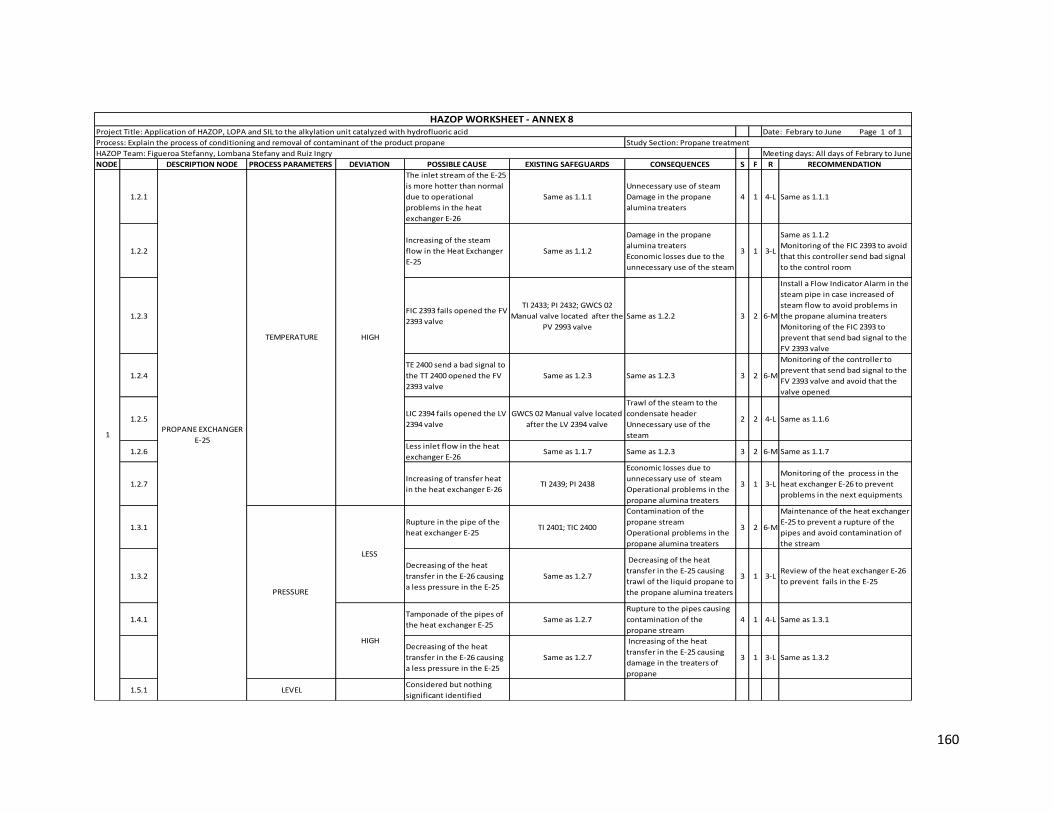
160
NODE DESCRIPTION NODE PROCESS PARAMETERS DEVIATION POSSIBLE CAUSE EXISTING SAFEGUARDS CONSEQUENCES S F R RECOMMENDATION
1.2.1
The inlet stream of the E-25
is more hotter than normal
due to operational
problems in the heat
exchanger E-26
Same as 1.1.1
Unnecessary use of steam
Damage in the propane
alumina treaters
4 1 4-L Same as 1.1.1
1.2.2
Increasing of the steam
flow in the Heat Exchanger
E-25
Same as 1.1.2
Damage in the propane
alumina treaters
Economic losses due to the
unnecessary use of the steam
3 1 3-L
Same as 1.1.2
Monitoring of the FIC 2393 to avoid
that this controller send bad signal
to the control room
1.2.3FIC 2393 fails opened the FV
2393 valve
TI 2433; PI 2432; GWCS 02
Manual valve located after the
PV 2993 valve
Same as 1.2.2 3 2 6-M
Install a Flow Indicator Alarm in the
steam pipe in case increased of
steam flow to avoid problems in
the propane alumina treaters
Monitoring of the FIC 2393 to
prevent that send bad signal to the
FV 2393 valve
1.2.4
TE 2400 send a bad signal to
the TT 2400 opened the FV
2393 valve
Same as 1.2.3 Same as 1.2.3 3 2 6-M
Monitoring of the controller to
prevent that send bad signal to the
FV 2393 valve and avoid that the
valve opened
1.2.5LIC 2394 fails opened the LV
2394 valve
GWCS 02 Manual valve located
after the LV 2394 valve
Trawl of the steam to the
condensate header
Unnecessary use of the
steam
2 2 4-L Same as 1.1.6
1.2.6Less inlet flow in the heat
exchanger E-26Same as 1.1.7 Same as 1.2.3 3 2 6-M Same as 1.1.7
1.2.7Increasing of transfer heat
in the heat exchanger E-26TI 2439; PI 2438
Economic losses due to
unnecessary use of steam
Operational problems in the
propane alumina treaters
3 1 3-L
Monitoring of the process in the
heat exchanger E-26 to prevent
problems in the next equipments
1.3.1Rupture in the pipe of the
heat exchanger E-25TI 2401; TIC 2400
Contamination of the
propane stream
Operational problems in the
propane alumina treaters
3 2 6-M
Maintenance of the heat exchanger
E-25 to prevent a rupture of the
pipes and avoid contamination of
the stream
1.3.2
Decreasing of the heat
transfer in the E-26 causing
a less pressure in the E-25
Same as 1.2.7
Decreasing of the heat
transfer in the E-25 causing
trawl of the liquid propane to
the propane alumina treaters
3 1 3-LReview of the heat exchanger E-26
to prevent fails in the E-25
1.4.1Tamponade of the pipes of
the heat exchanger E-25Same as 1.2.7
Rupture to the pipes causing
contamination of the
propane stream
4 1 4-L Same as 1.3.1
Decreasing of the heat
transfer in the E-26 causing
a less pressure in the E-25
Same as 1.2.7
Increasing of the heat
transfer in the E-25 causing
damage in the treaters of
propane
3 1 3-L Same as 1.3.2
1.5.1 LEVELConsidered but nothing
significant identified
HAZOP Team: Figueroa Stefanny, Lombana Stefany and Ruiz Ingry Meeting days: All days of Febrary to June
HAZOP WORKSHEET - ANNEX 8 Project Title: Application of HAZOP, LOPA and SIL to the alkylation unit catalyzed with hydrofluoric acid Date: Febrary to June Page 1 of 1
Process: Explain the process of conditioning and removal of contaminant of the product propane Study Section: Propane treatment
PRESSURE
TEMPERATURE
PROPANE EXCHANGER
E-25 1
HIGH
LESS
HIGH

161
NODE DESCRIPTION NODE PROCESS PARAMETERS DEVIATION POSSIBLE CAUSE EXISTING SAFEGUARDS CONSEQUENCES S F R RECOMMENDATION
2.1.1Decreasing of the heat
transfer in the E-25TI 2401; TIC 2400
Decreasing in the efficiency
in the remove of the
fluorides in the D-14 A/B
3 2 6-M
Review of the operation in the E-25
to maintain the removing of the
fluorides in the treaters
2.1.2Tamponade in the inlet
pipe of the D-14 A/BSame as 2.1.1
Overpressure in the pipe
causing posible rupture
Air pollution
Possible fire explosion
Risk to employees
Economic losses
4 2 8-M
Maintenance constant to the inlet
pipe to prevent an incident in the
unit
Install a pressure indicator in the
inlet pipe to the D-14 A/B to show
the flow of the propane
2.1.3
TE 2400 fails sending wrong
signal to the TIC 2400
opening the FV 2393 valve
Same as 2.1.1 Same as 2.1.1 3 2 6-M
Monitoring to the controller to
avoid fails in the signal to maintain
the operation in the D-14 A/B
2.1.4Inefficiency in the treaters
with alumina TI 2404 / 2403; TI 2406 / 2405 Same as 2.1.1 3 1 3-L
Monitoring of the process in the
treaters D-14 A/B to prevent
problems in the propane KOH
treater
2.1.5Decreasing of the inlet flow
of the treaters PI 2436 / 2438; TW 2437; TI 2439 Same as 2.1.1 3 2 6-M
Install a Flow Indicator in the inlet
pipe of the treaters to verify that
the flow is right
2.2.1Increasing of the heat
transfer in the E-25Same as 2.1.1
Damage in the propane
alumina treaters
Unnecessary use of the
steam causing economic
losses
4 2 8-M Same as 2.1.1
2.2.2Increasing of the inlet flow
of the treaters
Same as 2.1.5; XV 2396 located
in the inlet pipe of the E-26
Damage in the propane
alumina treaters
Inefficiency in the removal of
the fluoride
Contamination of the
propane stream
4 2 8-M Same as 2.1.5
2.2.3
TE 2400 fails sending wrong
signal to the TIC 2400
closing the FV 2393 valve
Same as 2.1.3
Same as 2.2.1
Possible overpressure in the
alumina treater
4 2 8-M Same as 2.1.3
2.2.4Inefficiency in the treaters
with alumina Same as 2.1.4 Same as 2.2.2 4 1 4-L Same as 2.1.4
2.2.5Tamponade of the exit pipe
of the treaters TI 2404; TI 2406
Possible overpressure in the
pipe causing a rupture in the
exit pipe
Operational problems in the
propane KOH treater
4 2 8-M
Maintenance constant to the exit
pipe to prevent an incident in the
unit and maintain the operation
HAZOP Team: Figueroa Stefanny, Lombana Stefany and Ruiz Ingry Meeting days: All days of Febrary to June
HAZOP WORKSHEET - ANNEX 8 Project Title: Application of HAZOP, LOPA and SIL to the alkylation unit catalyzed with hydrofluoric acid Date: Febrary to June Page 1 of 1
Process: Explain the process of conditioning and removal of contaminant of the product propane Study Section: Propane treatment
TEMPERATUREPROPANE ALUMINA
TREATERS D- 14 A/B2
LESS
HIGH
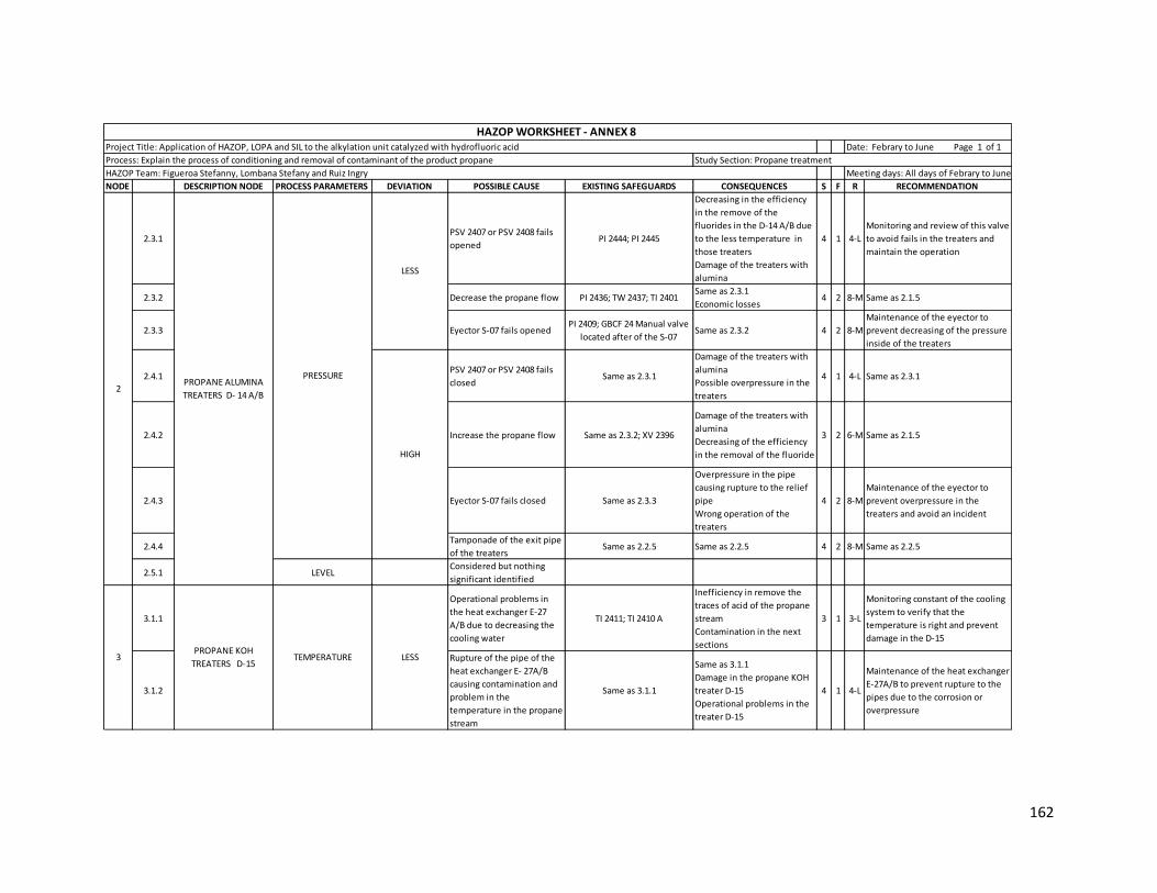
162
NODE DESCRIPTION NODE PROCESS PARAMETERS DEVIATION POSSIBLE CAUSE EXISTING SAFEGUARDS CONSEQUENCES S F R RECOMMENDATION
2.3.1PSV 2407 or PSV 2408 fails
opened PI 2444; PI 2445
Decreasing in the efficiency
in the remove of the
fluorides in the D-14 A/B due
to the less temperature in
those treaters
Damage of the treaters with
alumina
4 1 4-L
Monitoring and review of this valve
to avoid fails in the treaters and
maintain the operation
2.3.2 Decrease the propane flow PI 2436; TW 2437; TI 2401Same as 2.3.1
Economic losses 4 2 8-M Same as 2.1.5
2.3.3 Eyector S-07 fails opened PI 2409; GBCF 24 Manual valve
located after of the S-07Same as 2.3.2 4 2 8-M
Maintenance of the eyector to
prevent decreasing of the pressure
inside of the treaters
2.4.1PSV 2407 or PSV 2408 fails
closed Same as 2.3.1
Damage of the treaters with
alumina
Possible overpressure in the
treaters
4 1 4-L Same as 2.3.1
2.4.2 Increase the propane flow Same as 2.3.2; XV 2396
Damage of the treaters with
alumina
Decreasing of the efficiency
in the removal of the fluoride
3 2 6-M Same as 2.1.5
2.4.3 Eyector S-07 fails closed Same as 2.3.3
Overpressure in the pipe
causing rupture to the relief
pipe
Wrong operation of the
treaters
4 2 8-M
Maintenance of the eyector to
prevent overpressure in the
treaters and avoid an incident
2.4.4Tamponade of the exit pipe
of the treaters Same as 2.2.5 Same as 2.2.5 4 2 8-M Same as 2.2.5
2.5.1 LEVELConsidered but nothing
significant identified
3.1.1
Operational problems in
the heat exchanger E-27
A/B due to decreasing the
cooling water
TI 2411; TI 2410 A
Inefficiency in remove the
traces of acid of the propane
stream
Contamination in the next
sections
3 1 3-L
Monitoring constant of the cooling
system to verify that the
temperature is right and prevent
damage in the D-15
3.1.2
Rupture of the pipe of the
heat exchanger E- 27A/B
causing contamination and
problem in the
temperature in the propane
stream
Same as 3.1.1
Same as 3.1.1
Damage in the propane KOH
treater D-15
Operational problems in the
treater D-15
4 1 4-L
Maintenance of the heat exchanger
E-27A/B to prevent rupture to the
pipes due to the corrosion or
overpressure
HAZOP Team: Figueroa Stefanny, Lombana Stefany and Ruiz Ingry Meeting days: All days of Febrary to June
HAZOP WORKSHEET - ANNEX 8 Project Title: Application of HAZOP, LOPA and SIL to the alkylation unit catalyzed with hydrofluoric acid Date: Febrary to June Page 1 of 1
Process: Explain the process of conditioning and removal of contaminant of the product propane Study Section: Propane treatment
PRESSURE
2PROPANE ALUMINA
TREATERS D- 14 A/B
LESS
HIGH
LESS3 TEMPERATUREPROPANE KOH
TREATERS D-15

163
NODE DESCRIPTION NODE PROCESS PARAMETERS DEVIATION POSSIBLE CAUSE EXISTING SAFEGUARDS CONSEQUENCES S F R RECOMMENDATION
3.2.1
Operational problems in
the heat exchanger E-27
A/B due to increasing the
cooling water
Same as 3.1.1
Damage of the bed of KOH
Inefficiency in remove the
traces of acid of the propane
stream
Trawl of propane to the tea
system
3 1 3-L Same as 3.1.1
3.2.2Increasing of the traces of
acid in the propane stream TI 2410A/B; TDI 2410
Damage of the bed of KOH
Inefficiency in remove the
traces of acid of the propane
stream
3 1 3-L
Monitoring of the process in the HF
stripper to verify that the propane
stream come with little content of
acid
3.3.1Increasing the inlet flow of
the teatrer D-15TI 2406; TI 2404
Possible vaporization of the
hydrocarbon
Inefficiency in the removal of
traces of acid
Potential cavitation of the
pumps P-17 A/B
4 2 8-M
Install a Flow Indicator in the inlet
pipe of the D-15 to verify that the
flow is right and avoid problems in
the process of the tank
3.3.2 PSV 2414 fails opened
PI 2428; GBCF 13 Manual valve
located before of the PSV
2414
Trawl of thydrocarbon to the
tea system
Inefficiency in the removal of
traces of acid
3 2 6-M
Maintenance of the PSV 2414 to
avoid that fails opened and
maintain the operation in the
treater with KOH
3.3.3Tamponade of the pipe of
drainPI 2446; PI 2416; TI 2429
Increasing of the level in the
D-15 causing inefficiency in
the remove of the acid of the
propane stream
Increasing of the aqueous
phase in the inside of the
tank
3 1 3-L
Maintenance of the pipe to avoid
tamponade due to the aqueous
phase and prevent rupture of the
pipe and an incident
3.4.1Decreasing the inlet flow of
the teatrer D-15PSV 2414; Same as 3.3.1
Overpressure in the D-15
Increasing of the
temperature in the tank
3 3 9-M Same as 3.3.1
3.4.2 PSV 2414 fails closed Same as 3.3.2; LFCS04
Same as 3.4.1
Possible explosion of the
tank causing a great incident
in the unit
4 2 8-M
Maintenance of the PSV 2414 to
avoid that fails closed and maintain
the operation in the treater with
KOH and prevent an incident in the
plant
3.4.3Rupture to the exit pipe of
the D-15
PIC 2417; GBCF 13 Manual
valve located before of the PT
2417
Possible fire explosion
Air pollution
Risk to employees
Economic losses
Damage in the equipments
5 1 5-M
Monitoring and maintenance of the
pipe to prevent rupture and avoid
an incident
3.4.4 Rupture of the pipe of drain GWCS 07 Manual valve Same as 3.4.3 5 2 10-MSame as 3.3.3
3
HAZOP Team: Figueroa Stefanny, Lombana Stefany and Ruiz Ingry Meeting days: All days of Febrary to June
HAZOP WORKSHEET - ANNEX 8 Project Title: Application of HAZOP, LOPA and SIL to the alkylation unit catalyzed with hydrofluoric acid Date: Febrary to June Page 1 of 1
Process: Explain the process of conditioning and removal of contaminant of the product propane Study Section: Propane treatment
PRESSURE
LESS
HIGH
HIGHTEMPERATURE
PROPANE KOH
TREATERS D-15

164
NODE DESCRIPTION NODE PROCESS PARAMETERS DEVIATION POSSIBLE CAUSE EXISTING SAFEGUARDS CONSEQUENCES S F R RECOMMENDATION
3.5.1Rupture of the exit pipe of
the D-15PI 2416; TI 2429 Same as 3.4.3 5 1 5-L Same as 3.4.3
3.5.2
Operational problems in
the HF stripper casuing less
flow
TI 2411; TI 2410A
Operational problems in the
pumps P-17 A/B causing
cavitation and mechanical
damage in the pumps
Decreasing of the
concentration of propane in
the charge of olefins
4 2 8-M
Monitoring to the process in the HF
stripper to verify that the inlet flow
is right and maintain the operation
of the tank
3.5.3 Same as 3.4.4 Same as 3.4.4 Same as 3.4.3 5 2 10-MSame as 3.3.3
3.5.4Rupture in the inlet pipe of
the D-15
TI 2411; GBCF 13 Manual valve
located after of the TI 2411Same as 3.4.3 5 2 10-MSame as 3.4.3
3.5.5
GWCS07 Manual valve
located in the drain pipe
fails opened
PI 2446; LWCS 07 Manual valve
located under of the drain pot
Same as 3.5.2
Trawl of propane to the drain
pot causing an increase in the
exit propane
4 2 8-M
Install a Flow Indicator in the pipe
of drain to avoid problems in the
drain pot
3.5.6 PV-2417 malfunctions open
FIC-2415 with low flow
alarm; Operator procedures
and
training; GBCF 16 Manual valve
located after of the PV 2417
Potential vapors and
cavitation of the pump P-17
resulting in seals leaking
leading to loss of
containment
with potential for fire and
personnel injur
4 3 12-S
Consider adding a Low Flow Alarm
to FI-2423A and FI-2423B. (Propane
product flow to storage)
3.6.1Tamponade of the exit pipe
of the D-15Same as 3.5.1
Operational problems in the
tank causing contamination
of the propano and damage
in the equipment
3 1 3-L
Maintenance of the pipe to avoid
tamponade due to the aqueous
phase and prevent rupture of the
pipe and an incident
3.6.2
Operational problems in
the HF stripper casuing high
flow
Same as 3.5.2 No consequences of deviation 1 1 1-L
It is not necessary to establish
recommendations because it does
not represent any consequences
3.6.3
GWCS07 Manual valve
located in the drain pipe
fails closed
PI 2446; PI 2416; TI 2429
Contamination of the
propane stream with the
aqueous phase
Operational problems in the
next section due to the
contamination of the stream
3 3 9-M Same as 3.5.5
3
HIGH
LEVEL
HAZOP Team: Figueroa Stefanny, Lombana Stefany and Ruiz Ingry Meeting days: All days of Febrary to June
HAZOP WORKSHEET - ANNEX 8 Project Title: Application of HAZOP, LOPA and SIL to the alkylation unit catalyzed with hydrofluoric acid Date: Febrary to June Page 1 of 1
Process: Explain the process of conditioning and removal of contaminant of the product propane Study Section: Propane treatment
LESS
PROPANE KOH
TREATERS D-15

165
NODE DESCRIPTION NODE PROCESS PARAMETERS DEVIATION POSSIBLE CAUSE EXISTING SAFEGUARDS CONSEQUENCES S F R RECOMMENDATION
3.6.4
Rupture of the pipes of the
heat exchanger E-27 A/B
causing contamination of
the propane stream and
increasing of the inlet flow
Same as 3.5.2
Damage of the equipment
Contamination of the
propane stream causing
operational problems in the
next section
3 2 6-M Same as 3.1.2
3.6.5 P-17A/B pump stopsSpare pump, Pump run status,
FIC-2415 low flow alarm
Loss flow of product to
storage.
Stop flow from the HF
stripper
3 2 6-M
It is necessary to apply a
maintenance to the pumps to avoid
operational problems in the
process and maintain the inlet flow
in the other sections
3.6.6PV-2417 malfunctions
closed
Bypass around PV-2417; FIC-
2415 minimum flow
controller with low flow
alarm; PSV-2414 on the KOH
treater; PSV-2407/2408 on the
Alumina treater
Loss of flow of product to
storage.
Potential to dead head the
pumps resulting in seal leaks
and loss of containment with
potential for fire and
personnel
injury
Potential for overpressure in
the KOH and the Alumina
treaters. Potential for flange
leaks and loss of containment
with potential for fire and
personnel injury
4 3 12-S
Install a High Pressure Alarm in the
D-15 in case that the pressure
increases inside of the tank
3.7.1 NO Same as Less Same as Less Same as Less Same as Less
LEVELPROPANE KOH
TREATERS D-153
HAZOP Team: Figueroa Stefanny, Lombana Stefany and Ruiz Ingry Meeting days: All days of Febrary to June
HAZOP WORKSHEET - ANNEX 8 Project Title: Application of HAZOP, LOPA and SIL to the alkylation unit catalyzed with hydrofluoric acid Date: Febrary to June Page 1 of 1
Process: Explain the process of conditioning and removal of contaminant of the product propane Study Section: Propane treatment
HIGH
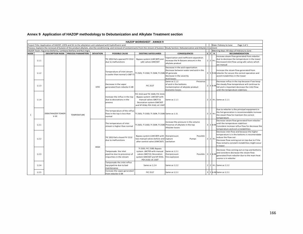
166
Annex 9 Application of HAZOP methodology to Debutanization and Alkylate Treatment section
NODE DESCRIPTION NODE PROCESS PARAMETERS DEVIATION POSSIBLE CAUSE EXISTING SAFEGUARDS CONSEQUENCES S F R RECOMMENDATION
1.1.1TIC 2013 fails opened FV 2112
due to malfunctions
Bypass system (LWC307) and
safe valves GWCS07
Vaporization and inefficient separation.
Increase the N-Butane amount in the
alkylate product
2 2 4-L
Increase steam flow generated from reboiler
due to decrease the temperature in the tower
Decreased inlet flow using safe valves which
are manual
1.1.2Temperature of inlet stream
is cooler than normal (<160° F)TI 2101; TI 2102; TI 2104; TI 2106
Decrease in the acid vaporization
Decrease between water and acid in the
HF generate
Decrease in the severity
Acid losses
3 3 9-M
Increase the steam flow generated from
reboiler for secure the correct operation and
avoid instabilities in the tower
1.1.3Decrease in the vapor
generated from reboiler E-09FIC 2117
Same as 1.1.2 Presence
of acid in the bottoms
Contamination of alkylate product
Economic losses
2 3 6-M
Decrease reflux in the top because if we keep
the steady flow temperature will continue to
fall and is important decrease the inlet flow
until the temperature stabilizes
1.1.4
Increase the reflux in the top
due to desviations in the
process
FIC 2112 and TIC 2103; FIC 2112;
Bypass system LWCS07 with
manual valves GBCF13;
Desviation system GWCS07
and SP 0156; PDI 2110; LIC 2107
Same as 1.1.1 2 2 4-L Same as 1.1.1
The temperature of the reflux
flow in the top is less than
normal
TI 2101; TI 2102; TI 2104; TI 2106 Same as 1.11 2 2 4-L
Due to reboiler is the principal equipment in
the hot generation is recommendable increase
the steam flow for maintain the correct
temperature
1.2.1The temperature of inlet
stream is higher than normalTI 2101; TI 2102; TI 2104; TI 2106
Increase the pressure in the column
Presence of alkylate in the top
Alkylate losses
3 2 6-M
Decrease steam flow generated from reboiler
until the temperature stabilizes
Considere increase reflux flow for decrease the
temperature and evit a instabilities
1.2.2TIC 2013 fails closed FV 2112
due to malfunctions
Bypass system (LWC307) with
two manual valves before and
after control valve (GWCS07)
Overpressure Possible
rupture Pumps
cavitation
2 2 4-L
Decrease inlet flow and because the higher
temperature is in the bottoms is recomendabe
reduce the flow out
Decrease flow coming out on top due to if the
flow remains constant instabilities might occur
in tower
1.2.3
Tamponade the inlet
pipeline due to prescence of
impurities in the stream
TI 2101; FIC 2100; Bypass
system LBCF05 with manual
valves GBCF13; Desviation
system GWCS07 and SP 0155;
PDI 2110; LIC 2107
Same as 1.2.1
Overpressure Possible
fire explosion
3 2 6-M
Decrease flow coming out on top and bottoms
and considere decrwase the steam flow
generated from reboiler due to the main heat
source is in reboiler
1.2.4
Tamponade the inlet reflux
top pipeline due to bad
maintenance
Same as 1.2.4 Same as 1.2.2 2 2 4-L Same as 1.2.2
1.2.5Increase the vapor generated
from reboiler E-09FIC 2117 Same as 1.2.1 3 2 6-M Same as 1.2.1
HAZOP WORKSHEET - ANNEX 9 Project Title: Application of HAZOP, LOPA and SIL to the alkylation unit catalyzed with hydrofluoric acid Date: Febrary to June Page 1 of 1
Process: Explains the removal of butane of the product alkylate, also the conditioning and removal of contaminants from the stream of butane Study Section: Debutanization and Alkylate treatment
HAZOP Team: Figueroa Stefanny, Lombana Stefany and Ruiz Ingry Meeting days: All days of Febrary to June
TEMPERATURE
LESS
HIGH
1DEBUTANIZER TOWER
V-01
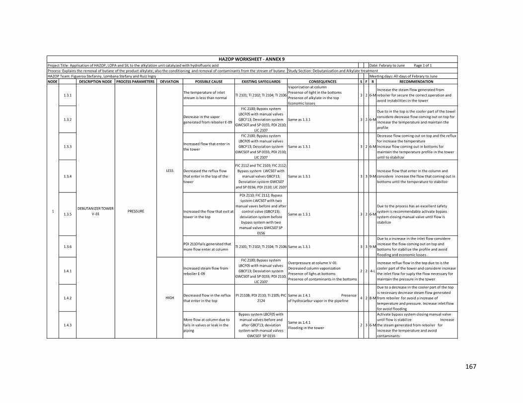
167
NODE DESCRIPTION NODE PROCESS PARAMETERS DEVIATION POSSIBLE CAUSE EXISTING SAFEGUARDS CONSEQUENCES S F R RECOMMENDATION
1.3.1The temperature of inlet
stream is less than normalTI 2101; TI 2102; TI 2104; TI 2106
Vaporization at column
Presence of light in the bottoms
Presence of alkylate in the top
Economic losses
3 2 6-M
Increase the steam flow generated from
reboiler for secure the correct operation and
avoid instabilities in the tower
1.3.2Decrease in the vapor
generated from reboiler E-09
FIC 2100; Bypass system
LBCF05 with manual valves
GBCF13; Desviation system
GWCS07 and SP 0155; PDI 2110;
LIC 2107
Same as 1.3.1 3 2 6-M
Due to in the top is the cooler part of the towel
considere decrease flow coming out on top for
increase the temperature and maintain the
profile
1.3.3Increased flow that enter in
the tower
FIC 2100; Bypass system
LBCF05 with manual valves
GBCF13; Desviation system
GWCS07 and SP 0155; PDI 2110;
LIC 2107
Same as 1.3.1 3 2 6-M
Decrease flow coming out on top and the reflux
for increase the temperature
Increase flow coming out in bottoms for
maintain the temperature profile in the tower
until to stabilize
1.3.4
Decreased the reflux flow
that enter in the top of the
tower
FIC 2112 and TIC 2103; FIC 2112;
Bypass system LWCS07 with
manual valves GBCF13;
Desviation system GWCS07
and SP 0156; PDI 2110; LIC 2107
Same as 1.3.1 3 3 9-M
Increase flow that enter in the column and
considere increase the flow that coming out in
bottoms until the temperature to stabilize
1.3.5Increased the flow that exit at
tower in the top
PDI 2110; FIC 2112; Bypass
system LWCS07 with two
manual vaves before and after
control valve (GBCF13);
desviation system before
bypass system with two
manual valves GWCS07 SP
0156
Same as 1.3.1 3 2 6-M
Due to the process has an excellent safety
system is recommendable activate bypass
system closing manual valve until flow is
stabilize
1.3.6PDI 2110 fails generated that
more flow enter at column TI 2101; TI 2102; TI 2104; TI 2106 Same as 1.3.1 3 3 9-M
Due to a increase in the inlet flow considere
increase the flow coming out on top and
bottoms for stabilize the profile and avoid
flooding and economic losses
1.4.1Increased steam flow from
reboiler E-09
FIC 2100; Bypass system
LBCF05 with manual valves
GBCF13; Desviation system
GWCS07 and SP 0155; PDI 2110;
LIC 2107
Overpressure at column V-01
Decreased column vaporization
Presence of lighs at bottoms
Presence of contaminants in the bottoms
2 2 4-L
Increase reflux flow in the top due to is the
cooler part of the tower and considere increase
the inlet flow for suply the flow necessary for
maintain the pressure in the tower
1.4.2Decreased flow in the reflux
that enter in the top
PI 2110B; PDI 2110; TI 2105; PIC
2124
Same as 1.4.1 Presence
of hydrocarbur vapor in the pipeline4 2 8-M
Due to a decrease in the cooler part of the top
is necessary decrease steam flow generated
from reboiler for avoid a increase of
temperature and pressure. Increase inlet flow
for avoid flooding
1.4.3
More flow at column due to
fails in valves or leak in the
piping
Bypass system LBCF05 with
manual valves before and
after GBCF13; deviation
system with manual valves
GWCS07 SP 0155
Same as 1.4.1
Flooding in the tower2 3 6-M
Activate bypass system closing manual valve
until flow is stabilize Increase
the steam generated from reboiler for
increase the temperature and avoid
contaminants
HIGH
PRESSUREDEBUTANIZER TOWER
V-011
HAZOP WORKSHEET - ANNEX 9 Project Title: Application of HAZOP, LOPA and SIL to the alkylation unit catalyzed with hydrofluoric acid Date: Febrary to June Page 1 of 1
Process: Explains the removal of butane of the product alkylate, also the conditioning and removal of contaminants from the stream of butane Study Section: Debutanization and Alkylate treatment
HAZOP Team: Figueroa Stefanny, Lombana Stefany and Ruiz Ingry Meeting days: All days of Febrary to June
LESS
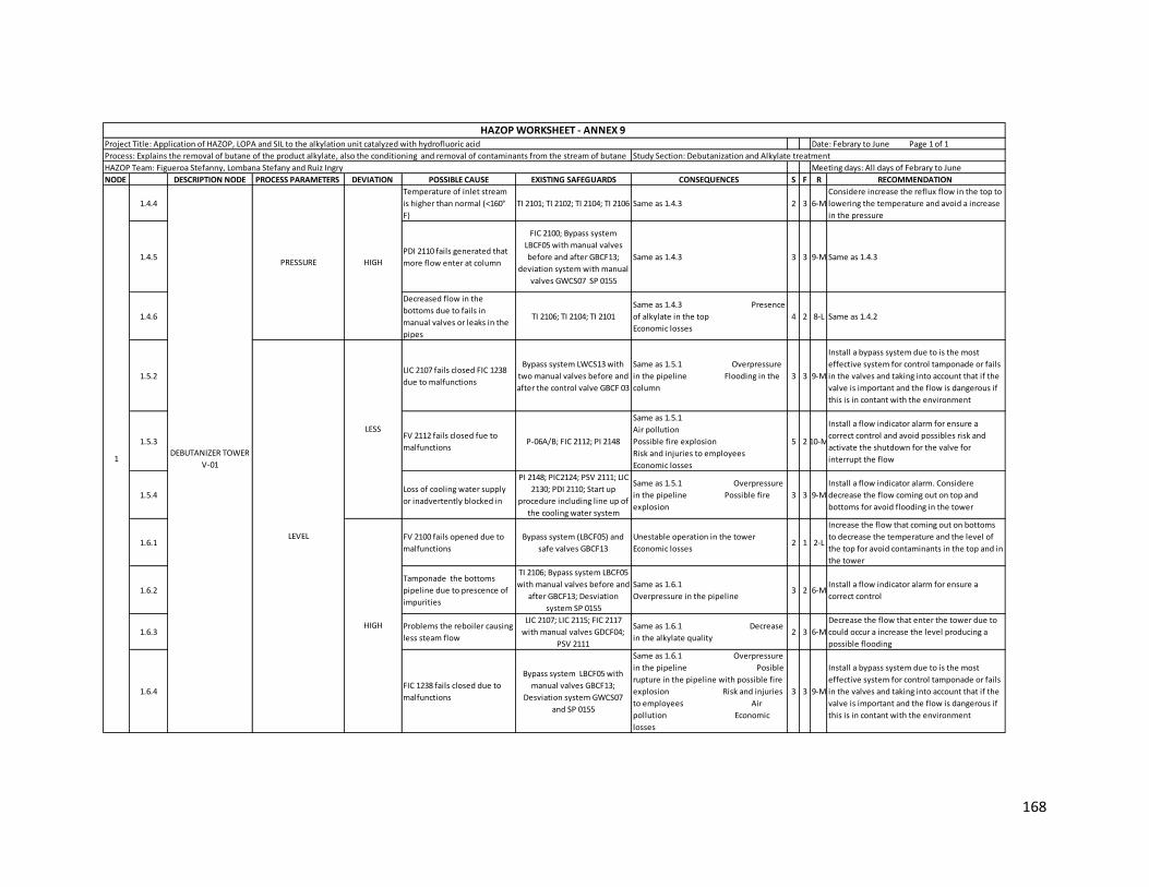
168
NODE DESCRIPTION NODE PROCESS PARAMETERS DEVIATION POSSIBLE CAUSE EXISTING SAFEGUARDS CONSEQUENCES S F R RECOMMENDATION
1.4.4
Temperature of inlet stream
is higher than normal (<160°
F)
TI 2101; TI 2102; TI 2104; TI 2106 Same as 1.4.3 2 3 6-M
Considere increase the reflux flow in the top to
lowering the temperature and avoid a increase
in the pressure
1.4.5PDI 2110 fails generated that
more flow enter at column
FIC 2100; Bypass system
LBCF05 with manual valves
before and after GBCF13;
deviation system with manual
valves GWCS07 SP 0155
Same as 1.4.3 3 3 9-M Same as 1.4.3
1.4.6
Decreased flow in the
bottoms due to fails in
manual valves or leaks in the
pipes
TI 2106; TI 2104; TI 2101
Same as 1.4.3 Presence
of alkylate in the top
Economic losses
4 2 8-L Same as 1.4.2
1.5.2LIC 2107 fails closed FIC 1238
due to malfunctions
Bypass system LWCS13 with
two manual valves before and
after the control valve GBCF 03
Same as 1.5.1 Overpressure
in the pipeline Flooding in the
column
3 3 9-M
Install a bypass system due to is the most
effective system for control tamponade or fails
in the valves and taking into account that if the
valve is important and the flow is dangerous if
this is in contant with the environment
1.5.3FV 2112 fails closed fue to
malfunctionsP-06A/B; FIC 2112; PI 2148
Same as 1.5.1
Air pollution
Possible fire explosion
Risk and injuries to employees
Economic losses
5 2 10-M
Install a flow indicator alarm for ensure a
correct control and avoid possibles risk and
activate the shutdown for the valve for
interrupt the flow
1.5.4Loss of cooling water supply
or inadvertently blocked in
PI 2148; PIC2124; PSV 2111; LIC
2130; PDI 2110; Start up
procedure including line up of
the cooling water system
Same as 1.5.1 Overpressure
in the pipeline Possible fire
explosion
3 3 9-M
Install a flow indicator alarm. Considere
decrease the flow coming out on top and
bottoms for avoid flooding in the tower
1.6.1FV 2100 fails opened due to
malfunctions
Bypass system (LBCF05) and
safe valves GBCF13
Unestable operation in the tower
Economic losses2 1 2-L
Increase the flow that coming out on bottoms
to decrease the temperature and the level of
the top for avoid contaminants in the top and in
the tower
1.6.2
Tamponade the bottoms
pipeline due to prescence of
impurities
TI 2106; Bypass system LBCF05
with manual valves before and
after GBCF13; Desviation
system SP 0155
Same as 1.6.1
Overpressure in the pipeline3 2 6-M
Install a flow indicator alarm for ensure a
correct control
1.6.3Problems the reboiler causing
less steam flow
LIC 2107; LIC 2115; FIC 2117
with manual valves GDCF04;
PSV 2111
Same as 1.6.1 Decrease
in the alkylate quality2 3 6-M
Decrease the flow that enter the tower due to
could occur a increase the level producing a
possible flooding
1.6.4FIC 1238 fails closed due to
malfunctions
Bypass system LBCF05 with
manual valves GBCF13;
Desviation system GWCS07
and SP 0155
Same as 1.6.1 Overpressure
in the pipeline Posible
rupture in the pipeline with possible fire
explosion Risk and injuries
to employees Air
pollution Economic
losses
3 3 9-M
Install a bypass system due to is the most
effective system for control tamponade or fails
in the valves and taking into account that if the
valve is important and the flow is dangerous if
this is in contant with the environment
PRESSURE HIGH
HAZOP WORKSHEET - ANNEX 9 Project Title: Application of HAZOP, LOPA and SIL to the alkylation unit catalyzed with hydrofluoric acid Date: Febrary to June Page 1 of 1
Process: Explains the removal of butane of the product alkylate, also the conditioning and removal of contaminants from the stream of butane Study Section: Debutanization and Alkylate treatment
HAZOP Team: Figueroa Stefanny, Lombana Stefany and Ruiz Ingry Meeting days: All days of Febrary to June
HIGH
LEVEL
LESS
1DEBUTANIZER TOWER
V-01
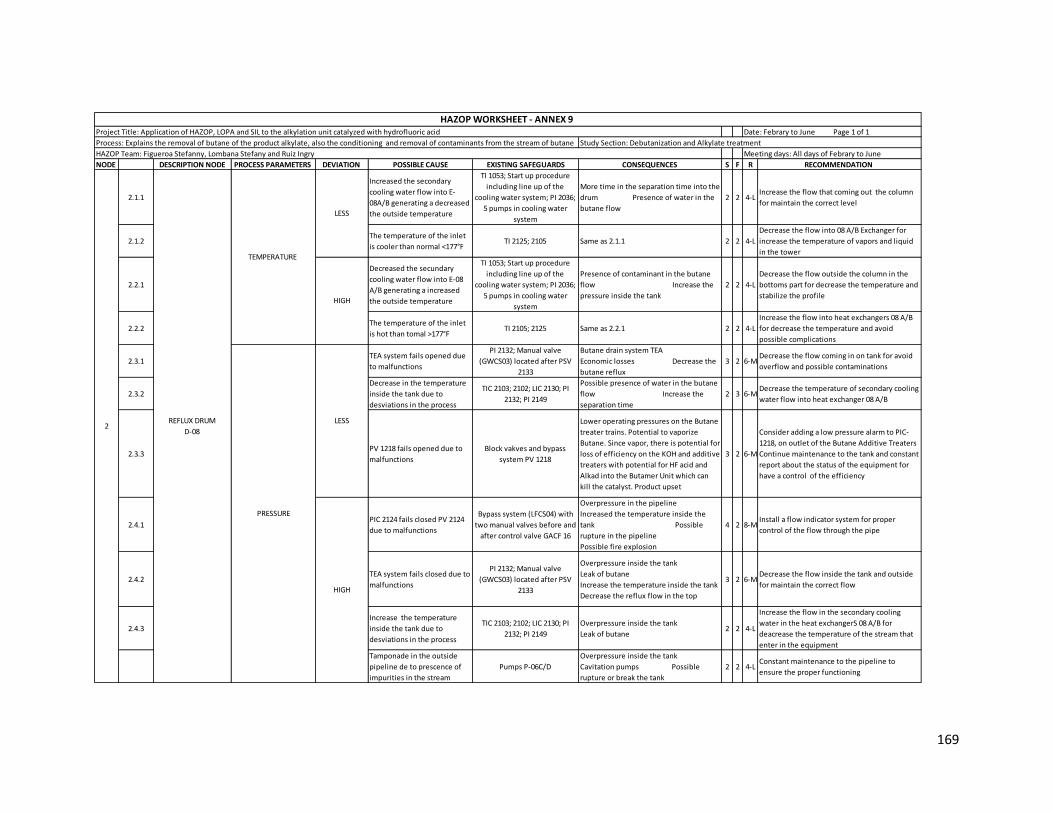
169
NODE DESCRIPTION NODE PROCESS PARAMETERS DEVIATION POSSIBLE CAUSE EXISTING SAFEGUARDS CONSEQUENCES S F R RECOMMENDATION
2.1.1
Increased the secondary
cooling water flow into E-
08A/B generating a decreased
the outside temperature
TI 1053; Start up procedure
including line up of the
cooling water system; PI 2036;
5 pumps in cooling water
system
More time in the separation time into the
drum Presence of water in the
butane flow
2 2 4-LIncrease the flow that coming out the column
for maintain the correct level
2.1.2The temperature of the inlet
is cooler than normal <177°FTI 2125; 2105 Same as 2.1.1 2 2 4-L
Decrease the flow into 08 A/B Exchanger for
increase the temperature of vapors and liquid
in the tower
2.2.1
Decreased the secundary
cooling water flow into E-08
A/B generating a increased
the outside temperature
TI 1053; Start up procedure
including line up of the
cooling water system; PI 2036;
5 pumps in cooling water
system
Presence of contaminant in the butane
flow Increase the
pressure inside the tank
2 2 4-L
Decrease the flow outside the column in the
bottoms part for decrease the temperature and
stabilize the profile
2.2.2The temperature of the inlet
is hot than tomal >177°FTI 2105; 2125 Same as 2.2.1 2 2 4-L
Increase the flow into heat exchangers 08 A/B
for decrease the temperature and avoid
possible complications
2.3.1TEA system fails opened due
to malfunctions
PI 2132; Manual valve
(GWCS03) located after PSV
2133
Butane drain system TEA
Economic losses Decrease the
butane reflux
3 2 6-MDecrease the flow coming in on tank for avoid
overflow and possible contaminations
2.3.2
Decrease in the temperature
inside the tank due to
desviations in the process
TIC 2103; 2102; LIC 2130; PI
2132; PI 2149
Possible presence of water in the butane
flow Increase the
separation time
2 3 6-MDecrease the temperature of secondary cooling
water flow into heat exchanger 08 A/B
2.3.3PV 1218 fails opened due to
malfunctions
Block vakves and bypass
system PV 1218
Lower operating pressures on the Butane
treater trains. Potential to vaporize
Butane. Since vapor, there is potential for
loss of efficiency on the KOH and additive
treaters with potential for HF acid and
Alkad into the Butamer Unit which can
kill the catalyst. Product upset
3 2 6-M
Consider adding a low pressure alarm to PIC-
1218, on outlet of the Butane Additive Treaters
Continue maintenance to the tank and constant
report about the status of the equipment for
have a control of the efficiency
2.4.1PIC 2124 fails closed PV 2124
due to malfunctions
Bypass system (LFCS04) with
two manual valves before and
after control valve GACF 16
Overpressure in the pipeline
Increased the temperature inside the
tank Possible
rupture in the pipeline
Possible fire explosion
4 2 8-MInstall a flow indicator system for proper
control of the flow through the pipe
2.4.2TEA system fails closed due to
malfunctions
PI 2132; Manual valve
(GWCS03) located after PSV
2133
Overpressure inside the tank
Leak of butane
Increase the temperature inside the tank
Decrease the reflux flow in the top
3 2 6-MDecrease the flow inside the tank and outside
for maintain the correct flow
2.4.3
Increase the temperature
inside the tank due to
desviations in the process
TIC 2103; 2102; LIC 2130; PI
2132; PI 2149
Overpressure inside the tank
Leak of butane 2 2 4-L
Increase the flow in the secondary cooling
water in the heat exchangerS 08 A/B for
deacrease the temperature of the stream that
enter in the equipment
Tamponade in the outside
pipeline de to prescence of
impurities in the stream
Pumps P-06C/D
Overpressure inside the tank
Cavitation pumps Possible
rupture or break the tank
2 2 4-LConstant maintenance to the pipeline to
ensure the proper functioning
REFLUX DRUM
D-082
TEMPERATURE
LESS
HIGH
PRESSURE
LESS
HIGH
HAZOP WORKSHEET - ANNEX 9 Project Title: Application of HAZOP, LOPA and SIL to the alkylation unit catalyzed with hydrofluoric acid Date: Febrary to June Page 1 of 1
Process: Explains the removal of butane of the product alkylate, also the conditioning and removal of contaminants from the stream of butane Study Section: Debutanization and Alkylate treatment
HAZOP Team: Figueroa Stefanny, Lombana Stefany and Ruiz Ingry Meeting days: All days of Febrary to June

170
NODE DESCRIPTION NODE PROCESS PARAMETERS DEVIATION POSSIBLE CAUSE EXISTING SAFEGUARDS CONSEQUENCES S F R RECOMMENDATION
2.5.1LIC 2130 fails opened FIC 2120
and 2121 due to malfunctions
Bypass system (LWCS07) with
two manual valves before and
after control valve (GBCF13);
the valve coun with SIS UC07
and vent system XV 2121
Possible cavitation and pumps damage in
the top of the column
Reflux losses
Increased temperature in the top of the
column
3 2 6-MActivate bypass system closing manual valve
until flow is stabilize
2.5.2
Overpressure in the inlet
pipeline causing possible
rupture
PIC 2124 ; LIC 2130; PI 2148 Air pollution. Possible fire explosion.
Risk to employees. Economic losses3 2 6-M
Periodic maintenance to pipes to ensure the
proper functioning and avoid possibles
accidents
2.5.4Decreasses the inlet flow due
to desviations in the processPIC 2124; PI 2148; LIC 2130 Same as 2.5.1 3 2 6-M
Decrease the flow coming out on tank for
maintain the level and correct separation
2.5.5
Tamponade in the inlet pipe
line due to prescence of
impurities in the stream
Same as 2.5.4
Same as 2.5.1
Overpressure with possible rupture the
pipeline. Air pollution. Risk to employees
Economic losses
4 2 8-M Same as 2.5.2
2.5.6PIC 2124 fails closed PV 2124
due to malfunctions
Bypass system (LFCS04) with
two manual valves before and
after control valve GACF 16
Same as 2.5.5 4 2 8-M
Due to the process has a security sistem wich is
bypass system is recommendable if this cause
occur activate bypass system
2.5.7 TEA system fails opened
PI 2132; Manual valve
(GWCS03) located after PSV
2133
Same as 2.5.1 Leak
to butane. Increase the air pollution3 2 6-M
Same as 2.5.6 Decrease
the flow that enter in the tank for avoid a
incomplete separation
2.6.1LIC 2113 fails closed FIC 2120
and 2121
Bypass system (LWCS07) with
two manual valves before and
after control valve (GBCF13);
the valve coun with SIS UC06
and vent system XV 2120
Overpressure in the D-08 and V-01
Presence of liquid in TEA system
Overpressure in the pipeline
Possible fire explosion
4 1 4-LDecrease the flow coming out on tank for
maintain the level and correct separation
2.6.2TEA system fails closed due to
malfunctions
PI 2132; Manual valve
(GWCS03) located after PSV
2133
Same as 2.6.1
Increase the contaminants substance
Economic losses due to leak of butane
4 2 8-M Same as 2.5.6
2.6.3PIC 2124 fails opened PV 2124
due to malfunctions
Bypass system (LFCS04) with
two manual valves before and
after control valve GACF 16
Same as 2.6.1 4 2 8-MInstall a flow indicator alarm for proper control
of the flow through the pipe
2.6.4
Increase the flow from
column due to desviations in
the process
PIC 2124; PI 2148; LIC 2130 Same as 2.6.1 4 2 8-M
Increase the flow coming out on tank for avoid
a flooding in the tank and contaminations of
the sustances
2.6.5Tamponade the butane
pipeline coming outLIC 2107; Pumps P-06 C/D
Overpressure the pipeline and tank
Possible fire explosion
Possible rupture in the tank
Air pollution
3 2 6-M
Decrease the flow that enter the tank for avoid
a possible flooding
Periodic maintenance of pipeline for proper
control of state of the equipment
REFLUX DRUM
D-082 LEVEL
LESS
HIGH
HAZOP WORKSHEET - ANNEX 9 Project Title: Application of HAZOP, LOPA and SIL to the alkylation unit catalyzed with hydrofluoric acid Date: Febrary to June Page 1 of 1
Process: Explains the removal of butane of the product alkylate, also the conditioning and removal of contaminants from the stream of butane Study Section: Debutanization and Alkylate treatment
HAZOP Team: Figueroa Stefanny, Lombana Stefany and Ruiz Ingry Meeting days: All days of Febrary to June
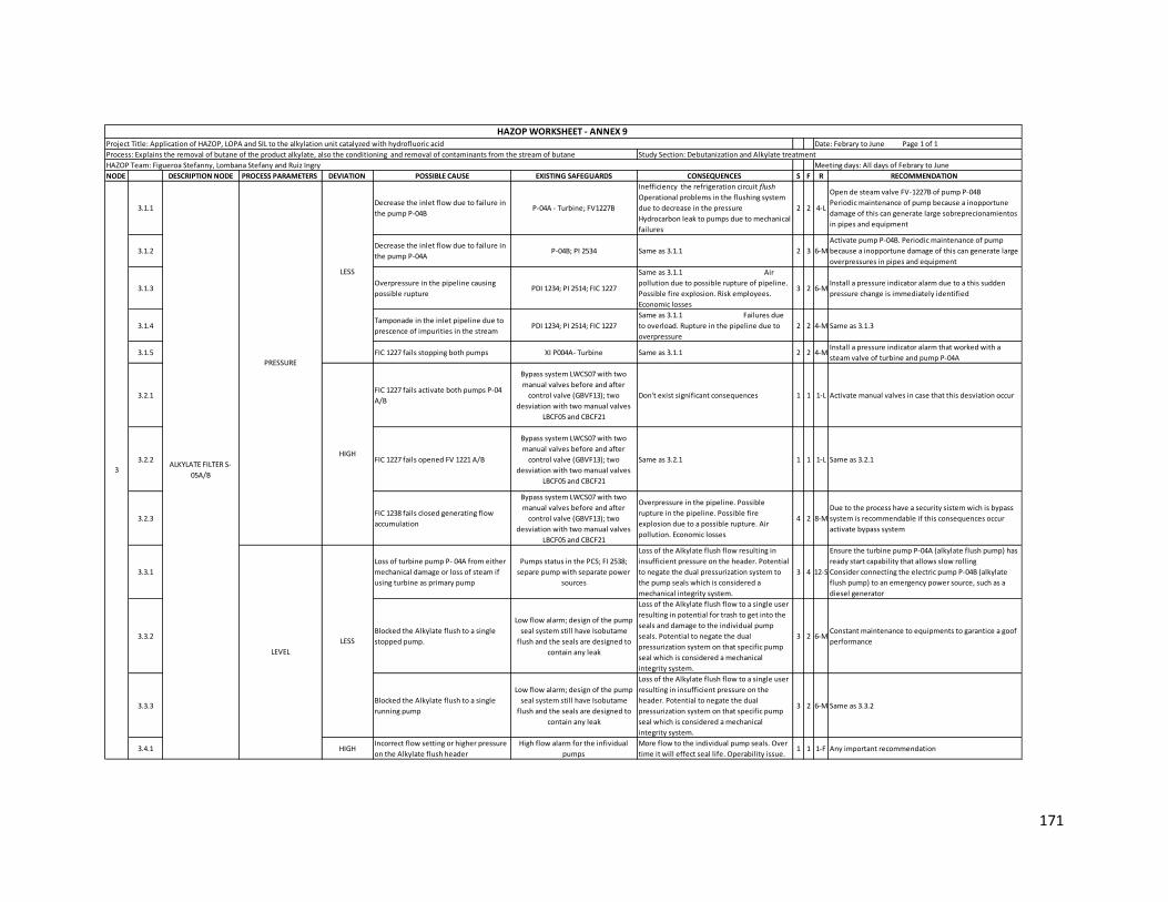
171
NODE DESCRIPTION NODE PROCESS PARAMETERS DEVIATION POSSIBLE CAUSE EXISTING SAFEGUARDS CONSEQUENCES S F R RECOMMENDATION
3.1.1Decrease the inlet flow due to failure in
the pump P-04BP-04A - Turbine; FV1227B
Inefficiency the refrigeration circuit flush
Operational problems in the flushing system
due to decrease in the pressure
Hydrocarbon leak to pumps due to mechanical
failures
2 2 4-L
Open de steam valve FV-1227B of pump P-04B
Periodic maintenance of pump because a inopportune
damage of this can generate large sobreprecionamientos
in pipes and equipment
3.1.2Decrease the inlet flow due to failure in
the pump P-04AP-04B; PI 2534 Same as 3.1.1 2 3 6-M
Activate pump P-04B. Periodic maintenance of pump
because a inopportune damage of this can generate large
overpressures in pipes and equipment
3.1.3Overpressure in the pipeline causing
possible rupturePDI 1234; PI 2514; FIC 1227
Same as 3.1.1 Air
pollution due to possible rupture of pipeline.
Possible fire explosion. Risk employees.
Economic losses
3 2 6-MInstall a pressure indicator alarm due to a this sudden
pressure change is immediately identified
3.1.4Tamponade in the inlet pipeline due to
prescence of impurities in the stream PDI 1234; PI 2514; FIC 1227
Same as 3.1.1 Failures due
to overload. Rupture in the pipeline due to
overpressure
2 2 4-M Same as 3.1.3
3.1.5 FIC 1227 fails stopping both pumps XI P004A- Turbine Same as 3.1.1 2 2 4-MInstall a pressure indicator alarm that worked with a
steam valve of turbine and pump P-04A
3.2.1FIC 1227 fails activate both pumps P-04
A/B
Bypass system LWCS07 with two
manual valves before and after
control valve (GBVF13); two
desviation with two manual valves
LBCF05 and CBCF21
Don't exist significant consequences 1 1 1-L Activate manual valves in case that this desviation occur
3.2.2 FIC 1227 fails opened FV 1221 A/B
Bypass system LWCS07 with two
manual valves before and after
control valve (GBVF13); two
desviation with two manual valves
LBCF05 and CBCF21
Same as 3.2.1 1 1 1-L Same as 3.2.1
3.2.3FIC 1238 fails closed generating flow
accumulation
Bypass system LWCS07 with two
manual valves before and after
control valve (GBVF13); two
desviation with two manual valves
LBCF05 and CBCF21
Overpressure in the pipeline. Possible
rupture in the pipeline. Possible fire
explosion due to a possible rupture. Air
pollution. Economic losses
4 2 8-M
Due to the process have a security sistem wich is bypass
system is recommendable if this consequences occur
activate bypass system
3.3.1
Loss of turbine pump P- 04A from either
mechanical damage or loss of steam if
using turbine as primary pump
Pumps status in the PCS; FI 2538;
separe pump with separate power
sources
Loss of the Alkylate flush flow resulting in
insufficient pressure on the header. Potential
to negate the dual pressurization system to
the pump seals which is considered a
mechanical integrity system.
3 4 12-S
Ensure the turbine pump P-04A (alkylate flush pump) has
ready start capability that allows slow rolling
Consider connecting the electric pump P-04B (alkylate
flush pump) to an emergency power source, such as a
diesel generator
3.3.2Blocked the Alkylate flush to a single
stopped pump.
Low flow alarm; design of the pump
seal system still have Isobutame
flush and the seals are designed to
contain any leak
Loss of the Alkylate flush flow to a single user
resulting in potential for trash to get into the
seals and damage to the individual pump
seals. Potential to negate the dual
pressurization system on that specific pump
seal which is considered a mechanical
integrity system.
3 2 6-MConstant maintenance to equipments to garantice a goof
performance
3.3.3Blocked the Alkylate flush to a single
running pump
Low flow alarm; design of the pump
seal system still have Isobutame
flush and the seals are designed to
contain any leak
Loss of the Alkylate flush flow to a single user
resulting in insufficient pressure on the
header. Potential to negate the dual
pressurization system on that specific pump
seal which is considered a mechanical
integrity system.
3 2 6-M Same as 3.3.2
3.4.1 HIGHIncorrect flow setting or higher pressure
on the Alkylate flush header
High flow alarm for the infividual
pumps
More flow to the individual pump seals. Over
time it will effect seal life. Operability issue.1 1 1-F Any important recommendation
3
LESS
ALKYLATE FILTER S-
05A/B
PRESSURE
LESS
HIGH
LEVEL
HAZOP WORKSHEET - ANNEX 9 Project Title: Application of HAZOP, LOPA and SIL to the alkylation unit catalyzed with hydrofluoric acid Date: Febrary to June Page 1 of 1
Process: Explains the removal of butane of the product alkylate, also the conditioning and removal of contaminants from the stream of butane Study Section: Debutanization and Alkylate treatment
HAZOP Team: Figueroa Stefanny, Lombana Stefany and Ruiz Ingry Meeting days: All days of Febrary to June

172
NODE DESCRIPTION NODE PROCESS PARAMETERS DEVIATION POSSIBLE CAUSE EXISTING SAFEGUARDS CONSEQUENCES S F R RECOMMENDATION
4.1.1 LESSTemperature of inlet is cooler than
normalNo safeguards Don't exist significant consequences 1 1 1-L Any recomendation
4.2.1 HIGHTemperature of inlet is higher than
normalNo safeguards Don't exist significant consequences 1 1 1-L Any recomendation
4.3.1Tamponade in the inlet pipeline due to
prescence of impurities in the stream
Bypass system (GACF16); Relief valve
GWCS07
Overpressure in the pipeline causing posible
rupture of the pipeline. Possible flooding in
the destillation colum V01. Less heat
exchangert in E-11 A/B and E-12 resulting in a
decrease of the temperature profile in the
destilation column V02. Presence of HF in the
alkylatE. Decrease in the alkylate production
4 2 8-MSame as 3.2.3 Periodic
maintance to pipeline to ensure proper operation
4.3.2Overpressure causing possible rupture
in the inlet pipelineSame as 4.3.1; FIC 1238
Same as 4.3.1 Air
pollution due to a possible rupture of the
pipeline. Possible fire explosion. Risk to
employees. Economic losses
3 2 6-M Same as 4.3.1
4.3.3FIC 1238 fails closed the valve 1238 due
to malfunctionsBypass system (LACF06) Same as 4.3.1 4 2 8-M
Due to the process has a security sistem wich is bypass
system is recommendable if this consequences occur
activate bypass system
4.3.4 Decrease the flow that entering to drum FIC 1238
Possible flooding in the destillation colum
V01. Less heat exchanger in E-11 A/B and E-12
resulting in a decrease of the temperature
profile in the destilation column V02.
Presence of HF in the alkylate. Decrease in the
alkylate production
4 2 8-MInstall a flow indicator alarm due to a this sudden flow
change is immediately identified
4.4.1FIC 1238 fails opened FV 1238 due to
malfunctionsBypass system (LACF06)
Possible decrease of leven in the distillation
column V-01 Flow
losses to flush system
3 2 6-M Same as 4.3.3
4.4.2 Increase the flow that entering to drum FIC 1238 Same as 4.4.1 3 2 6-M Same as 4.3.4
4.4.3 Increase the Potassium Hydroxide mass No safeguards Decrease alkylate product
Economic losses2 3 6-M
Periodic check to the equipments a pipeline where we
can get the correct status of them
4ALKYLATE TREATMENT
DRUM D-06
TEMPERATURE
PRESSURE
LESS
HIGH
HAZOP WORKSHEET - ANNEX 9 Project Title: Application of HAZOP, LOPA and SIL to the alkylation unit catalyzed with hydrofluoric acid Date: Febrary to June Page 1 of 1
Process: Explains the removal of butane of the product alkylate, also the conditioning and removal of contaminants from the stream of butane Study Section: Debutanization and Alkylate treatment
HAZOP Team: Figueroa Stefanny, Lombana Stefany and Ruiz Ingry Meeting days: All days of Febrary to June

173
Annex 10 Application of HAZOP methodology to N-Butane Treatment section
NODE DESCRIPTION NODE PROCESS PARAMETERS DEVIATION POSSIBLE CAUSE EXISTING SAFEGUARDS CONSEQUENCES S F R RECOMMENDATION
1.1.1
FIC 1312 and 1982 fails
closed FV 1312 and 1982
due to malfunctions
Bypass system (LWCS02) with
two manual valves before and
after control valve (GDCF06);
Vent System XY 1312 and SIS
UC06
Decrease the efficiency of
removing fluorides in the
treatments with alumina D-
09 A/B
1 1 1-L
Due to the process has a security
sistem wich is bypass system is
recommendable if this consequences
occur activate it
1.1.2Decrease the N-Butane
flow due to external events
LIC 2478/2482; PSV 2481; FIC
1312/1982
Decreased steam flow
Vapor leak to condensates
drum
1 1 1-L
Decrease the cooling water that enter
in the heat exchanger for decrease the
temperature of the flow that coming
out
1.1.3
LIC 2478 and 2482 fails
closed FV 2478 and 2482
due to malfunctions
Bypass system (LWCS02) with
two manual valves before and
after control valve (GDCF06)
Same as 1.1.1
Overpressure in the
pipeline causing possible
rupture
Economic losses
2 1 2-L Same as 1.1.1
1.1.4
Overpressure causing
possible rupture in the
enter pipeline
PI 1972; PI 1728
Same as 1.1.1
Air pollution
Risk to employees
Economic losses
2 3 6-M Same as 1.1.1
1.1.5
Tamponade in the inlet
pipeline due to prescence
of impurities in the stream
PI 1972; PI 1728
Same as 1.1.1
Possible rupture due to
overpressure
Air pollution
Economic losses
3 2 6-M Same as 1.1.1
1.2.1
FIC 1312 and 1982 fails
opened FV 1312 and 1982
due to malfunctinons
Bypass system (LWCS02) with
two manual valves before and
after control valve (GDCF06);
Vent System XY 1312 and SIS
UC06
Inefficient steam usage
Decreased the heat
exchanger in the E-14/14A
Overpressure in the D-
27/27A and in the E-14/14A
3 2 6-M Same as 1.1.1
1.2.2Increase the N-Butane flow
due to external events
LIC 2478/2482; FIC 1312/1982;
Bypass system (LWCS02) with
two manual valves before and
after control valve (GDCF06)
Same as 1.2.1 3 2 6-M Same as 1.1.4
1.2.3
The temperature of the
vapor steam is cooler than
normal due to desviations
in the process
LIC 2478/2482; TI 1731/1964 Same as 1.2.1 3 2 6-M Same as 1.2.1
1.3.1
FIC 1312 and 1982 fails
closed FV 1312 and 1982
due to malfunctions
Bypass system (LWCS02) with
two manual valves before and
after control valve (GDCF06);
Vent System XY 1312 and SIS
UC06
Condensate leak
Inefficient steam usage
Overpressure in the
pipeline causing possible
rupture
3 1 3-L Same as 1.1.1
1.3.2
LIC 2478 and 2482 fails
closed FV 2478 and 2482
due to malfunctions
Bypass system (LWCS02) with
two manual valves before and
after control valve (GDCF06)
Same as 1.3.1 3 1 3-L Same as 1.1.1
1.3.3
Overpressure causing
possible rupture in the
pipeline
PI 1972; PI 1728
Same as 1.3.1
Air pollution due to
possible rupture
Economic losses
3 2 6-L Same as 1.1.4
1.3.4
Tamponade in the inlet
pipeline due to prescence
of impurities in the stream
PI 1972; PI 1728 Same as 1.3.1 3 2 6-L Same as 1.1.4
TEMPERATURE
LESS
HIGH
LESSLEVEL
HEAT EXCHANGERS E-
14/14A AND CONDENSER
D-27/D27A
1
HAZOP Team: Figueroa Stefanny, Lombana Stefany and Ruiz Ingry Meeting days: All days of Febrary to June
HAZOP WORKSHEET - ANNEX 10 Project Title: Application of HAZOP, LOPA and SIL to the alkylation unit catalyzed with hydrofluoric acid Date: Febrary to June Page 1 of 1
Process: Explain the process of conditioning and removal of contaminant of the product N-Butane Study Section: N-Butane treatment

174
NODE DESCRIPTION NODE PROCESS PARAMETERS DEVIATION POSSIBLE CAUSE EXISTING SAFEGUARDS CONSEQUENCES S F R RECOMMENDATION
1.4.1
FIC 1312 and 1982 fails
opened FV 1312 and 1982
due to malfunctinons
Bypass system (LWCS02) with
two manual valves before and
after control valve (GDCF06);
Vent System XY 1312 and SIS
UC06
Decrease the heat
exchanger inn the E-
14/14A
Overpressure in the D-
27/27A and in the E-14/14A
2 1 2-L Same as 1.1.1
1.4.2
LIC 2478 and 2482 fails
opened FV 2478 and 2482
due to malfunctions
Bypass system (LWCS02) with
two manual valves before and
after control valve (GDCF06)
Same as 1.4.1 2 1 2-L Same as 1.1.1
2.1.1
TIC 1309/ 1974 fails closed
FV 1312/1962 due to
malfunctions
Bypass system (LWCS02) with
two manual valves before and
after control valve (GDCF06);
Vent System XY 1312 and SIS
UC06
Decrease in the efficiency
of removal of fluoride in
the alumina treater
1 1 1-L Same as 1.1.1
2.1.2
Tamponade in the inlet
pipeline due to prescence
of impurities in the stream
PI 1972; PSV 1304/1340 with
bypass system (LWCS07) and
manual valves GACF04 located
before and after bypass system
Same as 2.1.1
Overpressure in the
pipeline causing posible
rupture Air
pollution
Possible fire explosion
Risk to employees
Economic losses
3 2 6-M
Constant maintenance to the pipeline
to ensure the proper functioning
Install a flow indicator alarm
2.1.3
Overpressure in the inlet
pipeline causing possible
rupture in the pipeline
PI 1972; PSV 1304/1340 with
bypass system (LWCS07) and
manual valves GACF04 located
before and after bypass system
Same as 2.1.1
Air pollution
Possible fire explosion
Risk to employees
Economic losses
3 2 6-M Same as 2.1.2
2.1.4
LIC 2478/2482 fails closed
the valve LV 2482/2478 due
to malfunctions
Bypass system (LWCS02) with
two manual valves before and
after control valve (GDCF06)
Same as 2.1.1
Overpressure in the
pipeline causing posible
rupture Air
pollution
Possible fire explosion
Risk to employees
4 2 8-M
Due to the process have a security
sistem wich is bypass system is
recommendable if this consequences
occur activate it
2.1.5Tea system fails opened
due to malfunctions
Bypass system (LFCS04) and
manual valves GACF04 located
before and after bypass system
Same as 2.1.1
Air pollution due to
increase in the
components
Economic losses
4 2 8-M Same as 2.1.5
2.2.1
TIC 1309/ 1974 fails opened
FV 1312/1962 due to
malfunctions
Bypass system (LWCS02) with
two manual valves before and
after control valve (GDCF06);
Vent System XY 1312 and SIS
UC06
Increase in the design
temperature of alumina
treater D-09 A-D
1 1 1-L Same as 2.1.5
2.2.2
LIC 2478/2482 fails opened
the valve LV 2482/2478 due
to malfunctions
Bypass system (LWCS02) with
two manual valves before and
after control valve (GDCF06)
Same as 2.2.1 1 1 1-L Same as 2.1.5
HIGH
HEAT EXCHANGERS E-
14/14A AND CONDENSER
D-27/D27A
1 LEVEL
LESS
HIGH
TEMPERATURETREATERS WITH ALUMINA
D-09A-D2
HAZOP Team: Figueroa Stefanny, Lombana Stefany and Ruiz Ingry Meeting days: All days of Febrary to June
HAZOP WORKSHEET - ANNEX 10 Project Title: Application of HAZOP, LOPA and SIL to the alkylation unit catalyzed with hydrofluoric acid Date: Febrary to June Page 1 of 1
Process: Explain the process of conditioning and removal of contaminant of the product N-Butane Study Section: N-Butane treatment
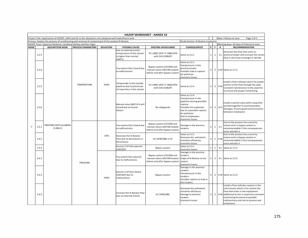
175
NODE DESCRIPTION NODE PROCESS PARAMETERS DEVIATION POSSIBLE CAUSE EXISTING SAFEGUARDS CONSEQUENCES S F R RECOMMENDATION
2.2.3
Due to external events
temperature of the stream
is higher than normal
(450°F)
TIC 1309/ 1974; TI 1306/1976
with SUS UC06/07Same as 2.2.1 1 1 1-L
Decrease the flow that enter to
alumina treater and increase the steam
flow in the heat exchanger E-14/14A
2.2.4Tea system fails closed due
to malfunctions
Bypass system (LFCS04) and
manual valves GACF04 located
before and after bypass system
Same as 2.2.1
Overpressure in the
alumina treater
Possible leak or rupture
Air pollution
Economic losses
3 2 6-M Same as 2.1.5
2.2.5
Tamponade in the outside
pipeline due to prescence
of impurities in the stream
TIC 1309/ 1974; TI 1306/1976
with SUS UC06/07Same as 2.2.4 3 3 9-M
Install a flow indicator alarm for proper
control of the flow through the pipe.
Constant maintenance to the pipeline
to ensure the proper functioning
2.2.6
Manual valve GBCF13 it will
closed due to human
factors
No safeguards
Same as 2.2.4
Overpressure in the
pipeline causing possible
rupture
Possible fire explosion
due to a possible rupture
Air pollution
Risk to employees
Economic losses
4 3 12-S
Install a control valve with a loop that
worked together to avoid possibles
damages. Ensure good communication
between employees
2.3.1Tea system fails closed due
to malfunctions
Bypass system (LFCS04) and
manual valves GACF04 located
before and after bypass system
Damage in the alumina
treaters 2 1 2-L
Due to the process has a security
sistem wich is bypass system is
recommendable if this consequences
occur activate it
2.3.2
Decrease the N-Butane
flow due to desviations in
the process
LIC 2478/2482; S-07
Same as 2.3.1
Decrease the pollutants
remotion efficiency
Economic losses
3 2 6-M
Due to the process has a security
sistem wich is bypass system is
recommendable if this consequences
occur activate it
2.3.3Eyector S-07 fails opened
(LWCS07)Bypass system
Same as 2.3.1
Economic losses2 2 4-L Same as 2.3.2
2.4.1Tea system fails opened
due to malfunctions
Bypass system (LFCS04) and
manual valves GACF04 located
before and after bypass system
Damage in the alumina
treaters
Scape of N-Butane to tea
system
Economic losses
2 2 4-L Same as 2.3.2
2.4.2
Eyector S-07 fails closed
(LWCS07) due to
malfunctions
Bypass system
Damage in the alumina
treaters
Overpressure in the
treaters
Possible rupture or leak in
the treaters
3 2 6-M Same as 2.3.2
2.4.3Increase the N-Butane flow
due to external eventsLIC 2478/2482
Decrease the pollutants
remotion efficiency
Damage to alumina
treaters
Economic losses
3 2 6-M
Install a flow indicator system in the
inlet stream which is for control the
flow that enter in the equipment
additional to this is required a constant
monitoring for prevent possible
malfunctions and risk to process and
employees
TREATERS WITH ALUMINA
D-09A-D2
PRESSURE
LESS
HIGH
TEMPERATURE HIGH
HAZOP Team: Figueroa Stefanny, Lombana Stefany and Ruiz Ingry Meeting days: All days of Febrary to June
HAZOP WORKSHEET - ANNEX 10 Project Title: Application of HAZOP, LOPA and SIL to the alkylation unit catalyzed with hydrofluoric acid Date: Febrary to June Page 1 of 1
Process: Explain the process of conditioning and removal of contaminant of the product N-Butane Study Section: N-Butane treatment

176
NODE DESCRIPTION NODE PROCESS PARAMETERS DEVIATION POSSIBLE CAUSE EXISTING SAFEGUARDS CONSEQUENCES S F R RECOMMENDATION
2.5.1
Decrease the N-Butane
flow due to desviations in
the process
LIC 2478/2482
Damage in the alumina
treaters Decrease
the pollutants remotion
efficiency
Economic losses
3 2 6-M
Is required install a flow indicator
system in the inlet stream for control
the flow and level in the tank because
this depends on the separation of
substances and prevents possible
contaminants
2.5.2P-06A/B pump fails due to
malfunctionsP-06 A/B; E-14/14A
Total loss of flow to both
treater sections. Loss of
flow to the individual train
vaporizers E-14/E-14A
heaters and D- 09A/B/C/D
Alumina treaters.
Potential damage to the
heaters resulting in
potential release of hot
steam. Potential
personnel safety concern.
3 2 6-M Same as 2.5.2
2.5.3FV 2121 fails closed due to
malfunctionsTI 1976/11977; TIC 1974; FV 2121
More flow through the
train leading to potentially
cooler temperatures for
the Alumina treaters. Loss
of absorption of the
organic fluorides on the
Alumina resulting in
increased organic fluorides
in the Butane product and
potential to kill the
catalyst in the Butamer
4 2 8-MConstant maintenance to valves and
report the real state of them
2.6.1 HIGH
Increase the N-Butane flow
due to desviation in the
process
LIC 2478/2482
Decrease the pressure in
the alumina treaters
Decrease the pollutants
remotion efficiency
Damage to alumina traters
Economic losses
3 2 6-M Same as 2.5.2
3.1.1
Decrease the N-butane
flow trater in the heat
exchangers E-15/E-15A
TW 1643/1645 - TW 1940/1938Decrease the water
remotion eficence1 1 1-L
Due to heat exchangers has the
responsibility of control the
temperature that enter in the
coalescer is necessary decrease the
cool secondary water in the heat
exchangers E-16/16A for maintain the
temperature
3.1.2
The temperature of N-
Butane is cooler than
normal
TI 1648/1943Any important
consequence1 1 1-L Any importat recomendation
3.1.3
Increase the secundary
water in the heat
exchangers E-16/16A
TI 1217A/1945A - TI 1648/1943Any important
consequence 1 1 1-L Any importat recomendation
TREATERS WITH ALUMINA
D-09A-D2
TEMPERATUREN-BUTANE COALESCERS
D10/10A3 LESS
LEVEL
LESS
HAZOP Team: Figueroa Stefanny, Lombana Stefany and Ruiz Ingry Meeting days: All days of Febrary to June
HAZOP WORKSHEET - ANNEX 10 Project Title: Application of HAZOP, LOPA and SIL to the alkylation unit catalyzed with hydrofluoric acid Date: Febrary to June Page 1 of 1
Process: Explain the process of conditioning and removal of contaminant of the product N-Butane Study Section: N-Butane treatment
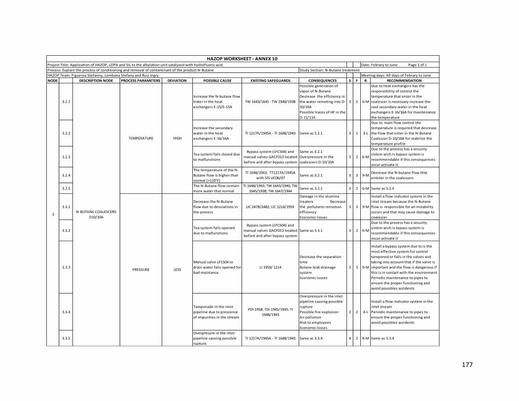
177
NODE DESCRIPTION NODE PROCESS PARAMETERS DEVIATION POSSIBLE CAUSE EXISTING SAFEGUARDS CONSEQUENCES S F R RECOMMENDATION
3.2.1
Increase the N-butane flow
trater in the heat
exchangers E-15/E-15A
TW 1643/1645 - TW 1940/1938
Possible generation of
vapor of N-Butane
Decrease the efficiency in
the water remoting into D-
10/10A
Possible traces of HF in the
D-11/11A
3 2 6-M
Due to heat exchangers has the
responsibility of control the
temperature that enter in the
coalescer is necessary increase the
cool secondary water in the heat
exchangers E-16/16A for maintenance
the temperature
3.2.2
Increase the secundary
water in the heat
exchangers E-16/16A
TI 1217A/1945A - TI 1648/1943 Same as 3.2.1 3 1 3-L
Due to main flow control the
temperature is required that decrease
the flow that enter in the N-Butane
Coalescer D-10/10A for stabilize the
temperature profile
3.2.3Tea system fails closed due
to malfunctions
Bypass system (LFCS04) and
manual valves GACF013 located
before and after bypass system
Same as 3.2.1
Overpressure in the
coalescers D-10/10A
3 2 6-M
Due to the process has a security
sistem wich is bypass system is
recommendable if this consequences
occur activate it
3.2.4
The temperature of the N-
Butane flow is higher than
normal (>110°F)
TI 1648/1943; TT1217A/1945A
with SIS UC06/07Same as 3.2.1 3 3 9-M
Decrease the N-butane flow that
enteter in the coalescers
3.2.5The N-Butane flow contain
more water that normal
TI 1648/1943; TW 1643/1940; TW
1645/1938; TW 1647/1944Same as 3.2.1 3 2 6-M Same as 3.2.4
3.3.1
Decrease the N-Butane
flow due to desviations in
the process
LIC 2478/2482; LIC 1214/1959
Damage in the alumina
treaters Decrease
the pollutants remotion
efficiency
Economic losses
3 3 9-M
Install a flow indicator system in the
inlet stream because the N-Butane
flow is responsible for an instability
occurs and that may cause damage to
coalescer
3.3.2Tea system fails opened
due to malfunctions
Bypass system (LFCS04) and
manual valves GACF013 located
before and after bypass system
Same as 3.3.1 3 2 6-M
Due to the process has a security
sistem wich is bypass system is
recommendable if this consequences
occur activate it
3.3.3
Manual valve LFCS04 to
drain water fails opened for
bad maintance
LI 1959/ 1214
Decrease the separation
time
Butane leak drainage
system
Economic losses
3 3 9-M
Install a bypass system due to is the
most effective system for control
tamponed or fails in the valves and
taking into account that if the valve is
important and the flow is dangerous if
this is in contact with the environment
Periodic maintenance to pipes to
ensure the proper functioning and
avoid possibles accidents
3.3.4
Tamponade in the inlet
pipeline due to prescence
of impurities in the stream
PDI 1958; TDI 1945/1945; TI
1648/1943
Overpressure in the inlet
pipeline causing possible
rupture
Possible fire explosion
Air pollution
Risk to employees
Economic losses
2 2 4-L
Install a flow indicator system in the
inlet stream
Periodic maintenance to pipes to
ensure the proper functioning and
avoid possibles accidents
3.3.5
Overpresure in the inlet
pipeline causing possible
rupture
TI 1217A/1945A - TI 1648/1943 Same as 3.3.4 4 2 8-M Same as 3.3.4
N-BUTANE COALESCERS
D10/10A3
TEMPERATURE
PRESSURE
HIGH
LESS
HAZOP Team: Figueroa Stefanny, Lombana Stefany and Ruiz Ingry Meeting days: All days of Febrary to June
HAZOP WORKSHEET - ANNEX 10 Project Title: Application of HAZOP, LOPA and SIL to the alkylation unit catalyzed with hydrofluoric acid Date: Febrary to June Page 1 of 1
Process: Explain the process of conditioning and removal of contaminant of the product N-Butane Study Section: N-Butane treatment
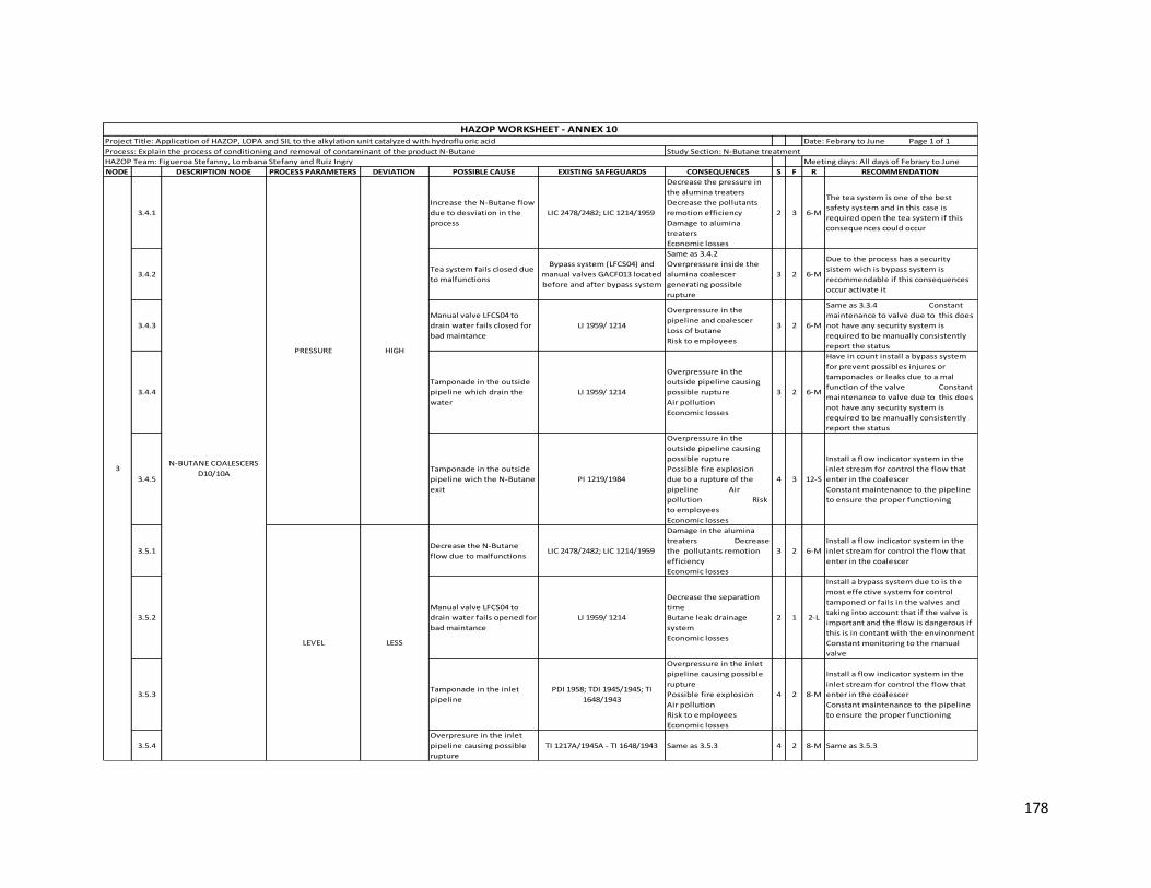
178
NODE DESCRIPTION NODE PROCESS PARAMETERS DEVIATION POSSIBLE CAUSE EXISTING SAFEGUARDS CONSEQUENCES S F R RECOMMENDATION
3.4.1
Increase the N-Butane flow
due to desviation in the
process
LIC 2478/2482; LIC 1214/1959
Decrease the pressure in
the alumina treaters
Decrease the pollutants
remotion efficiency
Damage to alumina
treaters
Economic losses
2 3 6-M
The tea system is one of the best
safety system and in this case is
required open the tea system if this
consequences could occur
3.4.2Tea system fails closed due
to malfunctions
Bypass system (LFCS04) and
manual valves GACF013 located
before and after bypass system
Same as 3.4.2
Overpressure inside the
alumina coalescer
generating possible
rupture
3 2 6-M
Due to the process has a security
sistem wich is bypass system is
recommendable if this consequences
occur activate it
3.4.3
Manual valve LFCS04 to
drain water fails closed for
bad maintance
LI 1959/ 1214
Overpressure in the
pipeline and coalescer
Loss of butane
Risk to employees
3 2 6-M
Same as 3.3.4 Constant
maintenance to valve due to this does
not have any security system is
required to be manually consistently
report the status
3.4.4
Tamponade in the outside
pipeline which drain the
water
LI 1959/ 1214
Overpressure in the
outside pipeline causing
possible rupture
Air pollution
Economic losses
3 2 6-M
Have in count install a bypass system
for prevent possibles injures or
tamponades or leaks due to a mal
function of the valve Constant
maintenance to valve due to this does
not have any security system is
required to be manually consistently
report the status
3.4.5
Tamponade in the outside
pipeline wich the N-Butane
exit
PI 1219/1984
Overpressure in the
outside pipeline causing
possible rupture
Possible fire explosion
due to a rupture of the
pipeline Air
pollution Risk
to employees
Economic losses
4 3 12-S
Install a flow indicator system in the
inlet stream for control the flow that
enter in the coalescer
Constant maintenance to the pipeline
to ensure the proper functioning
3.5.1Decrease the N-Butane
flow due to malfunctionsLIC 2478/2482; LIC 1214/1959
Damage in the alumina
treaters Decrease
the pollutants remotion
efficiency
Economic losses
3 2 6-M
Install a flow indicator system in the
inlet stream for control the flow that
enter in the coalescer
3.5.2
Manual valve LFCS04 to
drain water fails opened for
bad maintance
LI 1959/ 1214
Decrease the separation
time
Butane leak drainage
system
Economic losses
2 1 2-L
Install a bypass system due to is the
most effective system for control
tamponed or fails in the valves and
taking into account that if the valve is
important and the flow is dangerous if
this is in contant with the environment
Constant monitoring to the manual
valve
3.5.3Tamponade in the inlet
pipeline
PDI 1958; TDI 1945/1945; TI
1648/1943
Overpressure in the inlet
pipeline causing possible
rupture
Possible fire explosion
Air pollution
Risk to employees
Economic losses
4 2 8-M
Install a flow indicator system in the
inlet stream for control the flow that
enter in the coalescer
Constant maintenance to the pipeline
to ensure the proper functioning
3.5.4
Overpresure in the inlet
pipeline causing possible
rupture
TI 1217A/1945A - TI 1648/1943 Same as 3.5.3 4 2 8-M Same as 3.5.3
PRESSURE
LEVEL
N-BUTANE COALESCERS
D10/10A3
HIGH
LESS
HAZOP Team: Figueroa Stefanny, Lombana Stefany and Ruiz Ingry Meeting days: All days of Febrary to June
HAZOP WORKSHEET - ANNEX 10 Project Title: Application of HAZOP, LOPA and SIL to the alkylation unit catalyzed with hydrofluoric acid Date: Febrary to June Page 1 of 1
Process: Explain the process of conditioning and removal of contaminant of the product N-Butane Study Section: N-Butane treatment

179
NODE DESCRIPTION NODE PROCESS PARAMETERS DEVIATION POSSIBLE CAUSE EXISTING SAFEGUARDS CONSEQUENCES S F R RECOMMENDATION
3.6.1
Increase the N-Butane flow
due to desviation in the
process
LIC 2478/2482; LIC 1214/1959
Decrease the pressure in
the alumina treaters
Decrease the pollutants
remotion efficiency
Damage to alumina traters
Economic losses
4 2 8-M
The tea system is one of the best
safety system and in this case is
required open the tea system if this
consequences could occur
3.6.2
Manual valve LFCS04 to
drain water fails closed for
bad maintance
LI 1959/ 1214
Overpressure in the
pipeline and coalescer
Loss of butane
Risk to employees
3 2 6-M
Install a flow indicator system in the
inlet stream for control the flow that
enter in the coalescer
Constant maintenance to valve due to
this does not have any security system
is required to be manually consistently
report the status
3.6.3
Tamponade in the outside
pipeline which drain the
water
LI 1959/ 1214
Overpressure in the
outside pipeline causing
possible rupture
Air pollution
Economic losses
3 2 6-M Same as 3.5.2
3.6.4
Tamponade in the outside
pipeline wich the N-Butane
exit
PI 1219/1984
Overpressure in the
outside pipeline causing
possible rupture
Possible fire explosion
due to a rupture of the
pipeline
Air pollution
Risk to employees
Economic losses
4 2 8-M Same as 3.5.3
4.1.1Increase of cooling water
on E-16TDI 1217/1945
Decrease in the efficency
of pollutants remove
Decrease the pollutans
adsorption
2 2 4-L
Considere install a temperature alarm
indicator inside the treatments drums
worked with TDI 1217/1945 to control
the required flow in the drums
4.1.2The N-Butane temperature
is cooler than normal (>110)Same as 4.1.1 Same as 4.1.1 2 2 4-L Same as 4.1.1
4.1.3The N-Butane contain more
water than normal No safeguards Same as 4.1.1 2 3 6-M
Due to N-Butane contain more water
than normal is necessary decrease the
inlet flow at treatments drum for avoid
possible damages
Install a flow indicator system in the
inlet stream for control the flow that
enter in the KOH treatments
4.2.1Decrease of cooling water
on E-16TI 1013; PI 2036;
Increase the flourures
remotion 1 2 2-L Any importat recomendation
4.2.2The N-Butane temperature
is higher than normal (>110)TDI 1217/1945 Same as 4.2.1 1 2 2-L Any importat recomendation
LEVEL3N-BUTANE COALESCERS
D10/10A
4
HIGH
TEMPERATURE
LESS
HIGH
KOH TREATMENTS DRUMS
D 11/11A
HAZOP Team: Figueroa Stefanny, Lombana Stefany and Ruiz Ingry Meeting days: All days of Febrary to June
HAZOP WORKSHEET - ANNEX 10 Project Title: Application of HAZOP, LOPA and SIL to the alkylation unit catalyzed with hydrofluoric acid Date: Febrary to June Page 1 of 1
Process: Explain the process of conditioning and removal of contaminant of the product N-Butane Study Section: N-Butane treatment

180
NODE DESCRIPTION NODE PROCESS PARAMETERS DEVIATION POSSIBLE CAUSE EXISTING SAFEGUARDS CONSEQUENCES S F R RECOMMENDATION
4.3.1
Decrease the N-Butane
flow that enter to
treatments drums
PI 1219/1984
Decrease in the efficiency
of pollutants remove
Decrease the pollutants
adsorption
2 2 4-L
Install a flow indicator system in the
inlet stream for control the flow that
enter in the KOH treatments drums
Constant maintenance to the pipeline
to ensure the proper functioning
4.3.2
Overpressure in the
pipeline causing possible
rupture
PI 1219/1984
Same as 4.3.1
Air pollution due to
possible leak
Possible fire explosion
Risk to employees
Economic losses
3 3 9-MConstant maintenance to the pipeline
to ensure the proper functioning
4.3.3Tamponade in the inlet
pipelineSame as 4.3.2
Same as 4.3.2
Overpressure in the
pipeline causing possible
rupture
3 2 6-M Same as 4.3.2
4.3.4Tea system fails opened
due to malfunctions
Bypass system (LFCS04) and
manual valves GACF013 located
before and after bypass system
Same as 4.3.1
Air pollution due to
increase in the
contaminants flow
Economic losses
3 2 6-M
Due to the process have a security
sistem wich is bypass system is
recommendable if this desviation
occur activate it
4.3.5Draigane system fails
opened
LG 1216 Manual
valves GWCS07
Same as 4.3.2
Increase the
contaminations
3 1 3-L
The process has a manual valves which
are can activate if the principal valve
fails in this case is recommendable
activate manual valves
4.4.1
Increase the N-Butane flow
that enter to treatments
drums
PI 1219/1984
Increase in the
temperature which
promueve the fluorides
remove
2 2 4-L
Install a flow indicator system in the
inlet stream for control the flow that
enter in the KOH treatments drums
4.4.2Tea system falis closed due
to malfunctions
Bypass system (LFCS04) and
manual valves GACF013 located
before and after bypass system
Overpressure inside the
tank generating possible
leak
2 2 4-L Same as 4.3.5
4.4.3
Tamponade in the outside
pipeline due to prescence
of impurities in the stream
PI 1219/1984
Overpressure in the
pipeline causing possible
rupture
Air pollution due to
possible rupture
Possible fire explosion
Risk to employees
Economic losses
4 2 8-M
Constant monitoring and Periodic
maintance to pipeline to ensure
proper operation of the process
4.4.4Draigane system fails
closed due to human errors
LG 1216 Manual
valves GWCS07
Overpressure in the tank
causing possible leak
Air pollution due to
possible rupture
Economic losses
3 3 9-M
The proces has a manual valves wich
are can activate if the principal valve
fails in this case is recommendable
activate manual valves
4.4.5Tamponade in the
desviation systemManial valve GFCS04 Same as 4.4.3 4 2 8-M
The proces has a manual valves wich
are can activate if the principal valve
fails in this case is recommendable
close manual valves
KOH TREATMENTS DRUMS
D 11/11A4 PRESSURE
LESS
HIGH
HAZOP Team: Figueroa Stefanny, Lombana Stefany and Ruiz Ingry Meeting days: All days of Febrary to June
HAZOP WORKSHEET - ANNEX 10 Project Title: Application of HAZOP, LOPA and SIL to the alkylation unit catalyzed with hydrofluoric acid Date: Febrary to June Page 1 of 1
Process: Explain the process of conditioning and removal of contaminant of the product N-Butane Study Section: N-Butane treatment
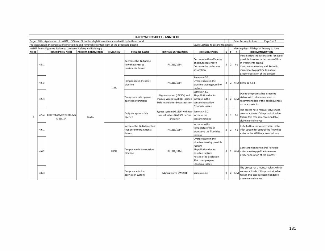
181
NODE DESCRIPTION NODE PROCESS PARAMETERS DEVIATION POSSIBLE CAUSE EXISTING SAFEGUARDS CONSEQUENCES S F R RECOMMENDATION
4.5.1
Decrease the N-Butane
flow that enter to
treatments drums
PI 1219/1984
Decrease in the efficiency
of pollutants remove
Decrease the pollutants
adsorption
2 2 4-L
Install a flow indicator alarm for avoid
possible increase or decrease of flow
at treatments drums
Constant monitoring and Periodic
maintance to pipeline to ensure
proper operation of the process
4.5.3Tamponade in the inlet
pipelinePI 1219/1984
Same as 4.5.2
Overpressure in the
pipeline causing possible
rupture
3 2 6-M Same as 4.5.2
4.5.4Tea system fails opened
due to malfunctions
Bypass system (LFCS04) and
manual valves GACF013 located
before and after bypass system
Same as 4.5.1
Air pollution due to
increase in the
contaminants flow
Economic losses
3 2 6-M
Due to the process has a security
sistem wich is bypass system is
recommendable if this consequences
occur activate it
4.5.4Draigane system fails
opened
Bypass system LG 1216 with two
manual valves GWCS07 before
and after
Same as 4.5.2
Increase the
contaminations
3 1 3-L
The proces has a manual valves wich
are can activate if the principal valve
fails in this case is recommendable
close manual valves
4.6.1
Increase the N-Butane flow
that enter to treatments
drums
PI 1219/1984
Increase in the
temperature which
promueve the fluorides
remove
2 2 4-L
Install a flow indicator system in the
inlet stream for control the flow that
enter in the KOH treatments drums
4.6.2Tamponade in the outside
pipelinePI 1219/1984
Overpressure in the
pipeline causing possible
rupture
Air pollution due to
possible rupture
Possible fire explosion
Risk to employees
Economic losses
4 2 8-M
Constant monitoring and Periodic
maintance to pipeline to ensure
proper operation of the process
4.6.3Tamponade in the
desviation systemManual valve GWCS04 Same as 4.4.3 3 2 6-M
The proces has a manual valves which
are can activate if the principal valve
fails in this case is recommendable
open manual valves
LEVEL
LESS
HIGH
KOH TREATMENTS DRUMS
D 11/11A4
HAZOP Team: Figueroa Stefanny, Lombana Stefany and Ruiz Ingry Meeting days: All days of Febrary to June
HAZOP WORKSHEET - ANNEX 10 Project Title: Application of HAZOP, LOPA and SIL to the alkylation unit catalyzed with hydrofluoric acid Date: Febrary to June Page 1 of 1
Process: Explain the process of conditioning and removal of contaminant of the product N-Butane Study Section: N-Butane treatment
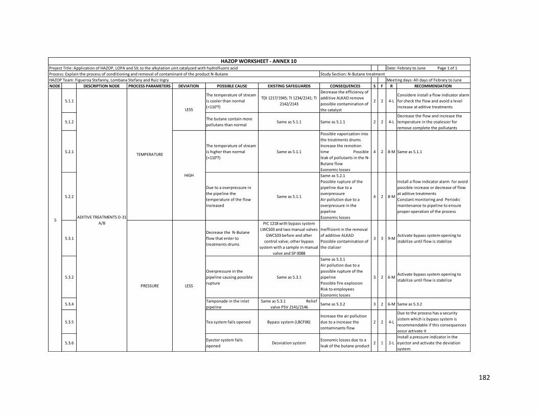
182
NODE DESCRIPTION NODE PROCESS PARAMETERS DEVIATION POSSIBLE CAUSE EXISTING SAFEGUARDS CONSEQUENCES S F R RECOMMENDATION
5.1.1
The temperature of stream
is cooler than normal
(<110°f)
TDI 1217/1945; TI 1234/2141; TI
2142/2143
Decrease the efficiency of
additive ALKAD remove
possible contamination of
the catalyst
2 2 4-L
Considere install a flow indicator alarm
for check the flow and avoid a level
increase at aditive treatments
5.1.2The butane contain more
pollutans than normalSame as 5.1.1 Same as 5.1.1 2 2 4-L
Decrease the flow and increase the
temperature in the coalescer for
remove complete the pollutants
5.2.1
The temperature of stream
is higher than normal
(<110°f)
Same as 5.1.1
Possible vaporization into
the treatments drums
Increase the remotion
time Possible
leak of pollutants in the N-
Butane flow
Economic losses
4 2 8-M Same as 5.1.1
5.2.2
Due to a overpressure in
the pipeline the
temperature of the flow
increased
Same as 5.1.1
Same as 5.2.1
Possible rupture of the
pipeline due to a
overpressure
Air pollution due to a
overpressure in the
pipeline
Economic losses
4 2 8-M
Install a flow indicator alarm for avoid
possible increase or decrease of flow
at aditive treatments
Constant monitoring and Periodic
maintenance to pipeline to ensure
proper operation of the process
5.3.1
Decrease the N-Butane
flow that enter to
treatments drums
PIC 1218 with bypass system
LWCS03 and two manual valves
GWCS03 before and after
control valve; other bypass
system with a sample in manual
valve and SP 0088
Inefficient in the removal
of additive ALKAD
Possible contamination of
the ctalizer
3 3 9-MActivate bypass system opening to
stabilize until flow is stabilize
5.3.2
Overpressure in the
pipeline causing possible
rupture
Same as 5.3.1
Same as 5.3.1
Air pollution due to a
possible rupture of the
pipeline
Possible fire explosion
Risk to employees
Economic losses
3 2 6-MActivate bypass system opening to
stabilize until flow is stabilize
5.3.4Tamponade in the inlet
pipeline
Same as 5.3.1 Relief
valve PSV 2141/2146Same as 5.3.2 3 2 6-M Same as 5.3.2
5.3.5 Tea system fails opened Bypass system (LBCF06)
Increase the air pollution
due to a increase the
contaminants flow
2 2 4-L
Due to the process has a security
sistem which is bypass system is
recommendable if this consequences
occur activate it
5.3.6Eyector system fails
openedDesviation system
Economic losses due to a
leak of the butane product2 1 2-L
Install a pressure indicator in the
eyector and activate the deviation
system
ADITIVE TREATMENTS D-31
A/B5
TEMPERATURE
LESS
HIGH
LESSPRESSURE
HAZOP Team: Figueroa Stefanny, Lombana Stefany and Ruiz Ingry Meeting days: All days of Febrary to June
HAZOP WORKSHEET - ANNEX 10 Project Title: Application of HAZOP, LOPA and SIL to the alkylation unit catalyzed with hydrofluoric acid Date: Febrary to June Page 1 of 1
Process: Explain the process of conditioning and removal of contaminant of the product N-Butane Study Section: N-Butane treatment

183
NODE DESCRIPTION NODE PROCESS PARAMETERS DEVIATION POSSIBLE CAUSE EXISTING SAFEGUARDS CONSEQUENCES S F R RECOMMENDATION
5.4.1
Increase the N-Butane flow
that enter to treatments
drums
PIC 1218 with bypass system
LWCS03 and two manual valves
GWCS03 before and after
control valve; other bypass
system with a sample in manual
valve and SP 0088
Increase the temperature
causing possible
vaporization of the N-
Butane
2 2 4-L
Install a flow indicator alarm for avoid
possible increase or decrease of flow
at aditive treatments
5.4.2Tea system falis closed due
to malfunctions
Bypass system (LBCF06) with
two manual valves GACF04 and
GBCF16 before and afeter safety
valve
Same as 5.4.1
Overpressure in the tank
causing possible hole
3 1 3-L Same as 5.3.5
5.4.3
Tamponade in the outside
pipeline due to prescence
of impurities in the stream
Same as 5.4.1
Same as 5.4.1
Overpressure in the
pipeline causing possible
rupture Air
pollution due to a possible
rupture Fire
explosion
Risk to employees
Economic losses
3 3 9-MPeriodic maintance to pipeline to
ensure proper operation
5.4.4PIC 1218 Fails closed PV
1218 due to malfunctions
Bypass system (LWCS03);
Desviation system with a
manual valve
Overpressure in the
pipeline generating
damage in the catalicer of
the U-106
Possible vaporization of
the hydrocarbon
Decreased the emotion in
the acid, water and aditive
3 2 6-M Same as 5.3.5
5.5.1
Decrease the N-Butane
flow that enter to
treatments drums
No safeguards
Decrease in the efficiency
of remove of the additive
ALKAD
Possible contamination of
the catalizer
2 3 6-M
Install a flow indicator alarm for avoid
possible increase or decrease of flow
at aditive treatments
5.5.2
Tamponade in the inlet
pipeline due to prescence
of impurities in the stream
Same as 5.5.2
Same as 5.5.2
Overpressure in the
pipeline causing possible
rupture
3 2 6-M Same as 5.5.2
5.5.3Tea system fails opened
due to malfunctionsBypass system (LBCF06)
Increase the pollution due
to escape to contaminants 2 1 2-L Same as 5.3.5
5.5.4PIC 1218 Fails opened PV
1218
Bypass system (LWCS03);
Desviation system with a
manual valve
Same as 5.5.1
Damage due to
overpressure in the D-01
and D-03 A/B
Increase the temperature
in the alumina treatments
D-09 A/B
3 2 5-M Same as 5.3.5
5.6.1
Increase the N-Butane flow
that enter to treatments
drums
Bypass system (LBCF06) with
two manual valves GACF04 and
GBCF16 before and afeter safety
valve
Possible vaporization into
the treatments drums
Increase the remotion
time
Damage in the catalicer
3 3 9-MInstall a flow indicator system in the
inlet of the treaters
5.6.2
Tamponade in the outside
pipeline due to prescence
of impurities in the stream
Bypass system (LBCF06) with
two manual valves GACF04 and
GBCF16 before and afeter safety
valve
Same as 5.6.1
Overpressure in the
pipeline
Possible rupture in the
pipeline with possible fire
explosion
3 3 9-m Same as 5.6.1
5.6.3PIC 1218 Fails closed PV
1219
Bypass system (LWCS03);
Desviation system with a
manual valve
Possible overpressure in
the pipeline causing a
ruptured
Overpressure in the
treaters
Damage in the catalizer
3 1 3-L Same as 5.3.5
HIGH
LEVEL
LESS
HIGH
PRESSURE
ADITIVE TREATMENTS D-31
A/B5
HAZOP Team: Figueroa Stefanny, Lombana Stefany and Ruiz Ingry Meeting days: All days of Febrary to June
HAZOP WORKSHEET - ANNEX 10 Project Title: Application of HAZOP, LOPA and SIL to the alkylation unit catalyzed with hydrofluoric acid Date: Febrary to June Page 1 of 1
Process: Explain the process of conditioning and removal of contaminant of the product N-Butane Study Section: N-Butane treatment

184
Annex 11 Application of HAZOP methodology to ALKAD Regeneration section
NODE DESCRIPTION NODE PROCESS PARAMETERS DEVIATION POSSIBLE CAUSE EXISTING SAFEGUARDS CONSEQUENCES S F R RECOMMENDATION
1.1.1 LESS
Considering but any possible
cause wasn't significant
identified
No safeguards Any important consequence 1 1 1-L Any recommendation
1.2.1 HIGH
Considering but any possible
cause wasn't significant
identified
No safeguards Any important consequence 1 1 1-L Any recommendation
1.3.1 LESSPCV 3049 fails opened due to
malfunctionsPCV 3048 nitrogen supply
Decreasse the pressure in the
drum
Possible ingrese of air or
moisture
Possible contamination of the
aditive
Economic losses
4 2 8-M
Constant checking of the valve
functioning and report the state
of the valve for prevent fails
1.4.1PCV 3048 fails closed due to
malfunctions
Relief valve PSV 3050;
PCV 3049; Manual valve
(PCV 3048)
Increase the nitrogen flow and
in the design pressure of the
drum D-103
Possible leak of the additive
Risk to employees
Economic losses
3 2 6-M
Due to the process count with a
relief system which is one of
the most important safety
systems is requirid opened if
this cause could occur
Considering install a bypass
system for avoid problems if
the principal valve fails
1.4.2Inadvertent blocking of the
discharge P-104A (pumps)Relief valve PSV 3050
Overpressuure in the discharge
piping and possible damage the
pump
Leak of aditive
Air pollution
Risk to employees
Economic losses
4 2 8-M
Periodic maintenance of pump
because a inopportune damage
of this can generate large
overpressures in pipes and
equipment
1.5.1 LESS
Considering but any possible
cause wasn't significant
identified
No safeguards Any important consequence 1 1 1-L Any recommendation
1.6.1 HIGH
Considering but any possible
cause wasn't significant
identified
No safeguards Any important consequence 1 1 1-L Any recommendation
PRESSURE
HIGH
LEVEL
1
FRESH ADDITIVE
CHARGE - ADDITIVE
STORAGE DRUM D-103
TEMPERATURE
HAZOP Team: Figueroa Stefanny, Lombana Stefany and Ruiz Ingry
HAZOP WORKSHEET - ANNEX 11 Project Title: Application of HAZOP, LOPA and SIL to the alkylation unit catalyzed with hydrofluoric acid Date: Febrary to June Page 1 of 1
Process: Explain the process of addition and regeneration of the additive to the reaction section Study Section: ALKAD Regenaration
Meeting days: All days of Febrary to June

185
NODE DESCRIPTION NODE PROCESS PARAMETERS DEVIATION POSSIBLE CAUSE EXISTING SAFEGUARDS CONSEQUENCES S F R RECOMMENDATION
2.1.1
Decrease the steam flow in
the E-104A-D due to external
events
XV 3111; FT 3069; FV 3065
Increase the HF in the bottomos
of the T-101
Decrease in the polymeric
contaminants
Loss in the acid quality
Increase of the production of
organic fluorics
Presence of polymer in the
reaction section
4 2 8-M
Decrease the acid stream that
passes through the heat
exchangers E-104A-D
Install a flow indicator alarma
that worked with LV3100
2.1.2
Decrease the steam flow in
the E-101A-B due to external
events
FV 3001; TI 3066 Same as 2.1.1 4 2 8-M Same as 2.1.1
2.1.3FIC 3001 Fails closed due to
malfunctions
Bypass system (LWCS02);
Manual valves (GDCF04)
Same as 2.1.1 Possible
overpressure with possible
rupture in the piping
Risk to employees
Air pollution
Equipment damage
Economic losses
4 2 8-M
Activate the bypass system for
mitigate or prevent injuries or
risk Constant
monitoring and check to
control loops for avoid probles
with the valves
2.1.4LV 3100 fails opened due to
malfunctions
Bypass system (LWCY01);
Manual valves before
and after that level valve
(GDCF06)
Decreasse the temperature of
the stream Same
as 2.1.1
Economic losses due to use
inefficient of vapor
3 2 6-M
Close the manual valve that be
before the control valve until
the flow is regulated
2.1.5LV 3090 fails closed due to
malfunctions
Bypass system (LWCS01);
Manual valves before
and after that level valve
(GBCF01)
Same as 2.1.4 3 2 6-M Same as 2.1.4
2.1.6FIC 3000 fails closed FV 3000
due to malfunctions
Bypass system (LBCF09);
Manual valves before
and after that flow valve
(GBCF22); Vent system
for supply air if is
neccesary
Decreasse the temperature of
the stream Same
as 2.1.1
Overpressure in the pipeline
generating possible air
pollution Risk to
employees due to acid leak
Economic losses
4 2 8-M
Activate vent system for supply
the requested air
Activate bypass system
2.1.7FIC 3065 fails opened FV 3065
due to malfunctions
Bypass system (LWCS07);
Manual valves before
and after that flow valve
(GBCF13)
Same as 2.1.6 4 2 8-M
Activate bypass system
Install a flow indicator alarm
worked with the flow indicator
control
2.1.8FIC 3039 fails closed FV 3039
due to malfunctions
Bypass system (LBCF09);
Manual valves before
and after that flow valve
(GBCF22)
Same as 2.1.1
Possible damage in the pumps 3 2 6-M
Decrease the flow that exit in
the bottoms for maintance the
temperature in the towel
Close the manual valve is
before the control valce until
the flow is regulated
2.1.9TIC 3012 fails closed TV 3012
due to malfunctions
Bypass system (LBNF01);
Manual valves before
and after that
temperature valve
(GBNF01); Vent system
for supply air if is
neccesary
No consequences for the
temperature in the column
Overpressure in the pipeline
causing possible rupture
Possible fire explosion
Risk to employees
Economic lossses
3 2 6-M
Activate vent system for supply
the requested air
Due to the process has a
security sistem which is bypass
system is recommendable if
this consequences occur
activate it
LESS
HAZOP Team: Figueroa Stefanny, Lombana Stefany and Ruiz Ingry
HAZOP WORKSHEET - ANNEX 11 Project Title: Application of HAZOP, LOPA and SIL to the alkylation unit catalyzed with hydrofluoric acid Date: Febrary to June Page 1 of 1
Process: Explain the process of addition and regeneration of the additive to the reaction section Study Section: ALKAD Regenaration
Meeting days: All days of Febrary to June
TEMPERATUREADDITIVE STRIPPER T-
1012
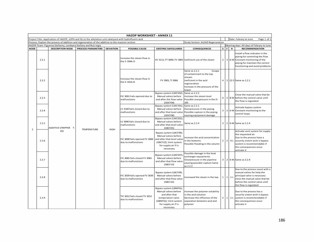
186
NODE DESCRIPTION NODE PROCESS PARAMETERS DEVIATION POSSIBLE CAUSE EXISTING SAFEGUARDS CONSEQUENCES S F R RECOMMENDATION
2.2.1Increase the steam flow in
the E-104A-DXV 3111; FT 3069; FV 3065 Ineficient use of the steam 2 3 6-M
Install a flow indicator in the
piping for controling the flow
Constant monitoring of the
piping for maintain the correct
functioning and avoid problems
2.2.2Increase the steam flow in
the E-101A-BFV 3001; TI 3066
Same as 2.2.1 Escape
of contaminant to the top
stream
Ineficient in the acid
regeneration
Increase in the pressure of the
tower
4 3 12-S Same as 2.2.1
2.2.3FIC 3001 Fails opened due to
malfunctions
Bypass system (LWCS02);
Manual valves before
and after the flow valve
(GDCF04)
Same as 2.2.2
Increase the steam level
Possible overpresure in the D-
105
4 2 8-M
Close the manual valve that be
before the control valve until
the flow is regulated
2.2.4LV 3100 fails closed due to
malfunctions
Bypass system (LWCY01);
Manual valves before
and after that level valve
(GDCF06)
Same as 2.2.1
Overpressure in the piping
Possible rupture in the piping
causing equipment damage
3 2 6-M
Activate bypass system
Constant monitoring to the
control loops
2.2.5LV 3090 fails closed due to
malfunctions
Bypass system (LWCS01);
Manual valves before
and after that level valve
(GBCF01)
Same as 2.2.4 3 2 6-M Same as 2.2.4
2.2.6FIC 3000 fails opened FV 3000
due to malfunctions
Bypass system (LBCF09);
Manual valves before
and after that level valve
(GBCF22); Vent system
for supply air if is
neccesary
Increase the acid concentration
in the bottoms
Possible flooding in the column
2 2 4-L
Activate vent system for supply
the requested air
Due to the process have a
security sistem wich is bypass
system is recommendable if
this consequences occur
activate it
2.2.7FIC 3065 fails closed FV 3065
due to malfunctions
Bypass system (LWCS07);
Manual valves before
and after that flow valve
(GBCF13)
Possible damage in the heat
exchanger equipments
Overpressure in the pipeline
causing possible rupture Same
as 2.2.2
3 2 6-M Same as 2.2.4
2.2.8FIC 3039 fails opened FV 3039
due to malfunctions
Bypass system (LBCF09);
Manual valves before
and after that flow valve
(GBCF22)
Increased the steam in the top 1 1 1-L
Due to the process count with a
manual valves for help the
principal valve is necessary
close the manual valve that be
before the control valve until
the flow is regulated
2.2.9TIC 3012 fails closed TV 3012
due to malfunctions
Bypass system (LBNF01);
Manual valves before
and after that
temperature valve
(GBNF01); Vent system
for supply air if is
neccesary
Increase the polymer solubility
in the acid solution
Decrease the efficence of the
separation between acid and
polymer
2 1 1-L
Due to the process has a
security sistem wich is bypass
system is recommendable if
this consequences occur
activate it
HIGH
HAZOP Team: Figueroa Stefanny, Lombana Stefany and Ruiz Ingry
HAZOP WORKSHEET - ANNEX 11 Project Title: Application of HAZOP, LOPA and SIL to the alkylation unit catalyzed with hydrofluoric acid Date: Febrary to June Page 1 of 1
Process: Explain the process of addition and regeneration of the additive to the reaction section Study Section: ALKAD Regenaration
Meeting days: All days of Febrary to June
TEMPERATUREADDITIVE STRIPPER T-
1012
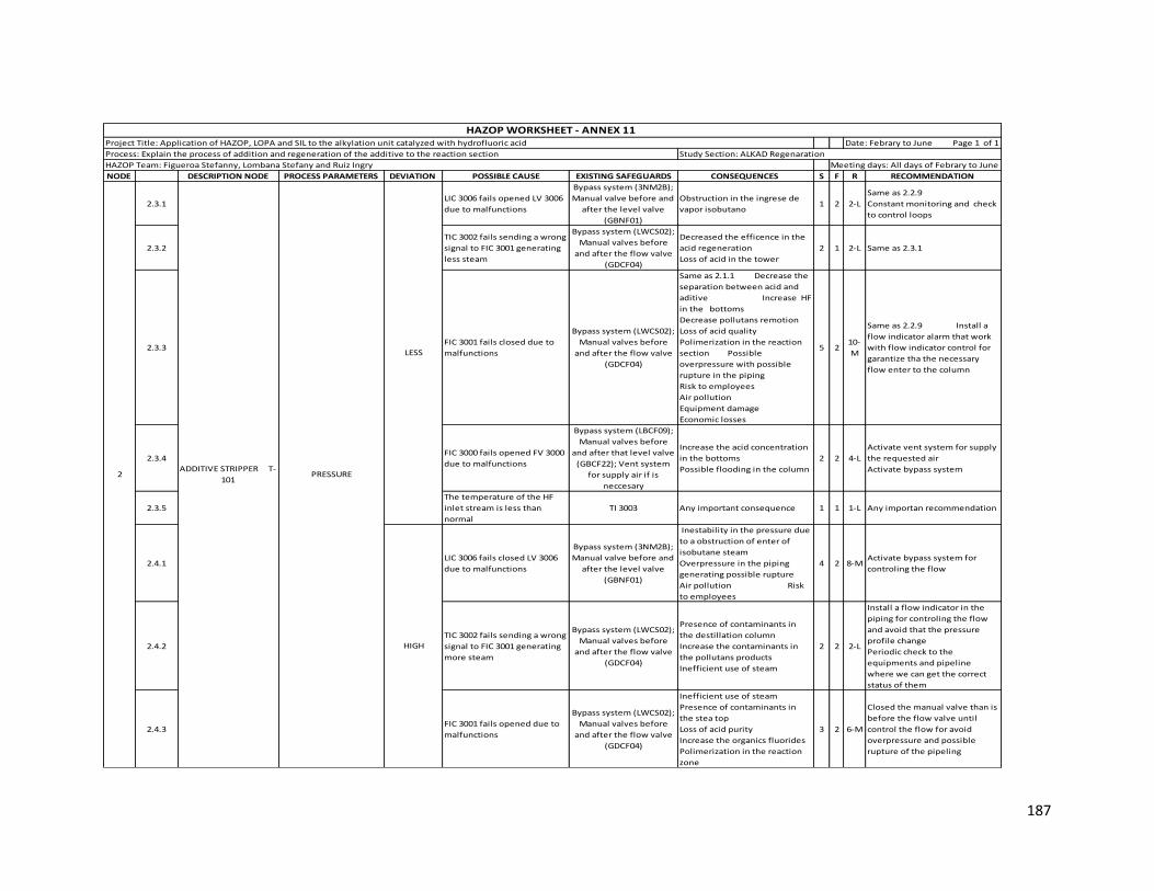
187
NODE DESCRIPTION NODE PROCESS PARAMETERS DEVIATION POSSIBLE CAUSE EXISTING SAFEGUARDS CONSEQUENCES S F R RECOMMENDATION
2.3.1LIC 3006 fails opened LV 3006
due to malfunctions
Bypass system (3NM2B);
Manual valve before and
after the level valve
(GBNF01)
Obstruction in the ingrese de
vapor isobutano1 2 2-L
Same as 2.2.9
Constant monitoring and check
to control loops
2.3.2
TIC 3002 fails sending a wrong
signal to FIC 3001 generating
less steam
Bypass system (LWCS02);
Manual valves before
and after the flow valve
(GDCF04)
Decreased the efficence in the
acid regeneration
Loss of acid in the tower
2 1 2-L Same as 2.3.1
2.3.3FIC 3001 fails closed due to
malfunctions
Bypass system (LWCS02);
Manual valves before
and after the flow valve
(GDCF04)
Same as 2.1.1 Decrease the
separation between acid and
aditive Increase HF
in the bottoms
Decrease pollutans remotion
Loss of acid quality
Polimerization in the reaction
section Possible
overpressure with possible
rupture in the piping
Risk to employees
Air pollution
Equipment damage
Economic losses
5 210-
M
Same as 2.2.9 Install a
flow indicator alarm that work
with flow indicator control for
garantize tha the necessary
flow enter to the column
2.3.4FIC 3000 fails opened FV 3000
due to malfunctions
Bypass system (LBCF09);
Manual valves before
and after that level valve
(GBCF22); Vent system
for supply air if is
neccesary
Increase the acid concentration
in the bottoms
Possible flooding in the column
2 2 4-L
Activate vent system for supply
the requested air
Activate bypass system
2.3.5
The temperature of the HF
inlet stream is less than
normal
TI 3003 Any important consequence 1 1 1-L Any importan recommendation
2.4.1LIC 3006 fails closed LV 3006
due to malfunctions
Bypass system (3NM2B);
Manual valve before and
after the level valve
(GBNF01)
Inestability in the pressure due
to a obstruction of enter of
isobutane steam
Overpressure in the piping
generating possible rupture
Air pollution Risk
to employees
4 2 8-MActivate bypass system for
controling the flow
2.4.2
TIC 3002 fails sending a wrong
signal to FIC 3001 generating
more steam
Bypass system (LWCS02);
Manual valves before
and after the flow valve
(GDCF04)
Presence of contaminants in
the destillation column
Increase the contaminants in
the pollutans products
Inefficient use of steam
2 2 2-L
Install a flow indicator in the
piping for controling the flow
and avoid that the pressure
profile change
Periodic check to the
equipments and pipeline
where we can get the correct
status of them
2.4.3FIC 3001 fails opened due to
malfunctions
Bypass system (LWCS02);
Manual valves before
and after the flow valve
(GDCF04)
Inefficient use of steam
Presence of contaminants in
the stea top
Loss of acid purity
Increase the organics fluorides
Polimerization in the reaction
zone
3 2 6-M
Closed the manual valve than is
before the flow valve until
control the flow for avoid
overpressure and possible
rupture of the pipeling
2
LESS
HAZOP Team: Figueroa Stefanny, Lombana Stefany and Ruiz Ingry
HAZOP WORKSHEET - ANNEX 11 Project Title: Application of HAZOP, LOPA and SIL to the alkylation unit catalyzed with hydrofluoric acid Date: Febrary to June Page 1 of 1
Process: Explain the process of addition and regeneration of the additive to the reaction section Study Section: ALKAD Regenaration
Meeting days: All days of Febrary to June
HIGH
PRESSUREADDITIVE STRIPPER T-
101
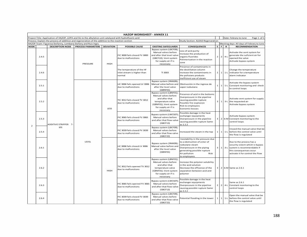
188
NODE DESCRIPTION NODE PROCESS PARAMETERS DEVIATION POSSIBLE CAUSE EXISTING SAFEGUARDS CONSEQUENCES S F R RECOMMENDATION
2.4.5FIC 3000 fails closed FV 3000
due to malfunctions
Bypass system (LBCF09);
Manual valves before
and after that level valve
(GBCF22); Vent system
for supply air if is
neccesary
Loss of acid purity
Increase the production of
organic fluorides
Polimerization in the reaction
zone
2 2 4-L
Activate the vent system for
generate the suficient air for
opened the valve
Activate bypass system
2.4.6
The temperature of the HF
inlet stream is higher than
normal
TI 3003
Presence of contaminants in
the destillation column
Increase the contaminants in
the pollutans products
Inefficient use of steam
2 1 1-L
Change the temperature
indicator for a temperature
alarm indicator
2.5.1LIC 3006 fails opened LV 3006
due to malfunctions
Bypass system (3NM2B);
Manual valve before and
after the level valve
(GBNF01)
Obstrucción in the ingrese de
vapor isobutano1 1 1-L
Activate the bypass system
Constant monitoring and check
to control loops
2.5.2TIC 3012 fails closed TV 3012
due to malfunctions
Bypass system (LBNF01);
Manual valves before
and after that
temperature valve
(GBNF01); Vent system
for supply air if is
neccesary
Presence of acid in the bottoms
Overpressure in the pipeline
causing possible rupture
Possible fire explosion
Risk to employees
Economic lossses
3 1 3-L
Activate vent system for supply
the requested air
Activate bypass system
2.5.3FIC 3065 fails closed FV 3065
due to malfunctions
Bypass system (LWCS07);
Manual valves before
and after that flow valve
(GBCF13)
Possible damage in the heat
exchanger equipments
Overpressure in the pipeline
causing possible rupture Same
as 2.2.2
3 2 6-M
Activate bypass system
Constant monitoring to the
control loops
2.5.4FIC 3039 fails closed FV 3039
due to malfunctions
Bypass system (LBCF09);
Manual valves before
and after that flow valve
(GBCF22)
Increased the steam in the top 1 1 1-L
Closed the manual valve that be
before the control valve until
the flow is regulated
2.6.1LIC 3006 fails closed LV 3006
due to malfunctions
Bypass system (3NM2B);
Manual valve before and
after the level valve
(GBNF01)
Inestability in the pressure due
to a obstruction of enter of
isobutane steam
Overpressure in the piping
generating possible rupture
Air pollution Risk
to employees
3 1 3-L
Due to the process has a
security sistem which is bypass
system is recommendable if
this consequences occur
activate it for control the flow
2.6.2TIC 3012 fails opened TV 3012
due to malfunctions
Bypass system (LBNF01);
Manual valves before
and after that
temperature valve
(GBNF01); Vent system
for supply air if is
neccesary
Increase the polymer solubility
in the acid solution
Decrease the efficence of the
separation between acid and
polymer
3 2 6-M Same as 2.6.1
2.6.3FIC 3065 fails opened FV 3065
due to malfunctions
Bypass system (LWCS07);
Manual valves before
and after that flow valve
(GBCF13)
Possible damage in the heat
exchanger equipments
Overpressure in the pipeline
causing possible rupture Same
as 2.2.2
2 2 4-L
Same as 2.6.1
Constant monitoring to the
control loops
2.6.4FIC 3039 fails closed FV 3039
due to malfunctions
Bypass system (LBCF09);
Manual valves before
and after that flow valve
(GBCF22)
Potential flooding in the tower 1 1 1-L
Open the manual valve that be
before the control valve until
the flow is regulated
PRESSURE HIGH
LEVEL
LESS
HIGH
HAZOP Team: Figueroa Stefanny, Lombana Stefany and Ruiz Ingry
HAZOP WORKSHEET - ANNEX 11 Project Title: Application of HAZOP, LOPA and SIL to the alkylation unit catalyzed with hydrofluoric acid Date: Febrary to June Page 1 of 1
Process: Explain the process of addition and regeneration of the additive to the reaction section Study Section: ALKAD Regenaration
Meeting days: All days of Febrary to June
ADDITIVE STRIPPER T-
1012

189
NODE DESCRIPTION NODE PROCESS PARAMETERS DEVIATION POSSIBLE CAUSE EXISTING SAFEGUARDS CONSEQUENCES S F R RECOMMENDATION
3.1.1 LESS
Cooling water is more cooler
than normal due to
enviromental effects
TI 3084 Any important consequence 1 1 1-L Any recommendation
3.2.1 HIGH
Decrease the cooling water
flow due to fails in manual
valves or decrease in the flow
TI 3084
Possible vaporization of HF in
the tank Increasse
the time of separation
2 2 4-L
Considere install a flow
indicator alarm in the cooling
water piping for chek the
correct temperature in this
stream
3.3.1PIC 3026 fails closed PV 3026
due to malfunctions
Bypass system (LBCF09);
Manual valves before
and after the pressure
valve; PIC 3026; LIC 3032;
PI 3112; Bypass system
All flow is forced through the
condensers
Over time potential to have
high level in the receivers
creating back pressure
Potential to overpressure the
Additive Stripper Risk to
employees
Economic losses
4 2 8-M
Same as 2.6.1
Periodic check to the
equipment and pipeline where
we can get the correct status of
them
3.3.2FIC 3040 fails closed FV 3040
due to malfunctions
Bypass system (LBCF09);
Manual valves before
and after the pressure
valve (GBCF22)
Same as 3.3.1
Overpressure in the piping
generating possible rupture
4 2 8-M Same as 3.3.1
3.4.1 HIGHPIC 3026 fails opened PV 3026
due to malfunctions
Bypass system (LBCF09);
Manual valves before
and after the pressure
valve; PIC 3026; LIC 3032;
PI 3112; Bypass system
Loss of flow through
condensers
Potential to overpressure the
Additive Stripper
Risk to employees
3 2 6-M Same as 3.3.1
3.5.1FV 3039 fails opened due to
malfunctions
LIC 3006; Bypass system
(LBCF09) Potential flooding in the tower 1 1 1-L
Open the manual valve that be
before the control valve until
the flow is regulated
3.5.2FV 3038 fails closed due to
malfunctionsBypass system (LBCF09)
Possible lost of nivel of the
interfase acid/isobutane in the
D-102 Cavitation
of the P-102 A/B
2 1 2-L Same as 3.3.1
3.5.3FV 3037 fails opened due to
malfunctions
A manual valve after the
flow valve (GBCF22)
Decrease the removal of the
contaminants of the acid
Losses of acid purity
Increase the production of
organics fluorides
3 2 6.M
Closed the manual valve
Install a flow indicator that
worked with flow indicator
control
3.5.4FV 3035 fails closed due to
malfunctionsBypass system (LBCF09)
Cavitation in the pumps P-103
A/B2 2 4-L
Due to the process have a
security sistem wich is bypass
system is recommendable if
this consequences occur
activate it for control the flow
3.6.1FV 3037 fails opened due to
malfunctions
P 103A-B; FIC 3035; A
manual valve after the
flow valve (GBCF22)
Increase the acid loss in the
bottoms of V-03
Possible flooding in the V-03
2 2 4-L
Activate the valve that is after
the flow valve to control the
flow
3.6.2FV 3035 fails closed due to
malfunctions
FIC 3039; P-102A/B;
Bypass system (LBCF09)
Increase the level in the D-103
More time of separation
between acid and isobutane
Overpressure with possible
rupture in the piping
3 2 6-M Same as 3.5.4
3ADDITIVE STRIPPER
RECEIVER D-102
TEMPERATURE
PRESSURE
LESS
LEVEL
LESS
HIGH
HAZOP Team: Figueroa Stefanny, Lombana Stefany and Ruiz Ingry
HAZOP WORKSHEET - ANNEX 11 Project Title: Application of HAZOP, LOPA and SIL to the alkylation unit catalyzed with hydrofluoric acid Date: Febrary to June Page 1 of 1
Process: Explain the process of addition and regeneration of the additive to the reaction section Study Section: ALKAD Regenaration
Meeting days: All days of Febrary to June

190
NODE DESCRIPTION NODE PROCESS PARAMETERS DEVIATION POSSIBLE CAUSE EXISTING SAFEGUARDS CONSEQUENCES S F R RECOMMENDATION
4.1.1 LESS
Considering but any possible
cause wasn't significant
identified
Any safeguards Any important consequence 1 1 1-L Any recommendation
4.2.1 HIGH
Loss of cooling water the E-
102A-G due to fails in manual
valves or in the stream
TI 3015
Stop the slip stream flow
through the E-102 Potential
hotter temperatures in the
Bottom Separator leading to
hotter Polymer to the Polymer
Surge Drum and Neutralizing
Drum Potential for higher
corrosion rates leading to
vessel replacement and
reduced capacity to neutralize
4 3 12-S
Install a flow indicator in the
Cooling Water system to ensure
the temperature profile in the
column
4.3.1 LESS
Considering but any possible
cause wasn't significant
identified
No safeguards Any important consequence 1 1 1-L Any recommendation
4.4.1 HIGH
Considering but any possible
cause wasn't significant
identified
No safeguards Any important consequence 1 1 1-L Any recommendation
4.5.1 LESS
Considering but any possible
cause wasn't significant
identified
No safeguards Any important consequence 1 1 1-L Any recommendation
4.5.2LV 3006 fails closed due to
malfunctions
Bypass system (3NM2B);
Manual valve before and
after the level valve
(GBNF01)
Lower interface level in the
separator and potential to send
Polymer with the Complex to
the Alky Unit Over time loss of
acid purity. Resulting in acid
runaway Potential for
corrosion, leaks, and personnel
injury
4 2 8-M
Same as 3.5.4
Periodic check to the
equipments and pipeline
where we can get the correct
status of them
4.5.3LV 3021 fails opened due to
malfunctions
Bypass system (LDNF01);
Manual valve before and
after the level valve
(GDNF01)
Higher Polymer flow to the
Polymer Surge Drum Higher
interface level in the bottom
separator Potential for some of
the Complex to get into the
Polymer Surge Drum
3 2 6-M Same as 4.5.2
4.5.4TV 3012 fails opened due to
malfunctions
Bypass system (LBNF01);
Manual valves before
and after that
temperature valve
(GBNF01); Vent system
for supply air if is
neccesary
Potential to cool the bottoms of
the separator to approximately
100 degrees Potential to cool
the Polymer below its pour
point and plugging/fouling in
the bottom circuit Worst case is
having to shutdown Alkad to
clean the bottoms circuit
4 2 8-M
Same as 4.5.2
Activate vent system for close
the valve to operational values
4
FLOW
HIGH
TEMPERATURE
PRESSURE
HAZOP Team: Figueroa Stefanny, Lombana Stefany and Ruiz Ingry
HAZOP WORKSHEET - ANNEX 11 Project Title: Application of HAZOP, LOPA and SIL to the alkylation unit catalyzed with hydrofluoric acid Date: Febrary to June Page 1 of 1
Process: Explain the process of addition and regeneration of the additive to the reaction section Study Section: ALKAD Regenaration
Meeting days: All days of Febrary to June
ADDITIVE STRIPPER
BOTTOMS SEPARATOR
D-101

191
NODE DESCRIPTION NODE PROCESS PARAMETERS DEVIATION POSSIBLE CAUSE EXISTING SAFEGUARDS CONSEQUENCES S F R RECOMMENDATION
4.6.1P-101 pumps stop due to
malfunctions
LIC 3021; PIC 3026; LAH
3023
Stop flow of Complex to the
Alky Unit Potential for higher
interface level in the Bottoms
Separator, D-101 The loss of
flow out of the Bottoms
Separator can result in higher
levels in the Additive Stripper,
T-101 Worse case is the
potential for overpressure of
the Additive Stripper overhead
system resulting in potential for
loss of containment
4 2 8-M
Periodic maintenance of pump
because a inopportune damage
of this can generate large
overpressures in pipes and
equipment
Considered install a turbine for
generate more energy in the
pumps and ensure their
function
4.6.2LV 3006 fails closed due to
malfunctions
Bypass system (3NM2B);
Manual valve before and
after the level valve
(GBNF01)
The loss of flow out of the
Bottoms Separator resulting in
higher levels in the Additive
Stripper. Worse case is the
potential for overpressure of
the Additive Stripper overhead
system resulting in potential for
loss of containment. Potential
for fire and personnel injury.
4 2 8-M
Due to the process has a
security sistem which is bypass
system is recommendable if
this consequences occur
activate it for control the flow
Stop flow of Complex to the
Alky Unit
Potential for higher interface
level in the Bottoms Separator.
4.6.3LV 3021 fails opened due to
malfunctions
Bypass system (LDNF01);
Manual valve before and
after the level valve
(GDNF01)
Lower interface level in the
separator and potential to send
Polymer with the Complex to
the Alky Unit Over time loss of
acid purity Resulting in acid
runaway Potential for
corrosion, leaks, and personnel
injury
4 2 8-M
Stop Polymer flow to the
Polymer Surge Drum
Activate vent system for try to
open the valve Due
to the process have a security
sistem wich is bypass system is
recommendable if this
consequences occur activate it
for control the flow
4.6.4TV 3012 fails closed due to
malfunctions
Bypass system (LBNF01);
Manual valves before
and after that
temperature valve
(GBNF01); Vent system
for supply air if is
neccesary
Potential hotter temperatures
in the Bottom Separator leading
to hotter Polymer to the
Polymer Surge Drum and
Neutralizing Drum Potential for
higher corrosion rates leading
to vessel replacement and
reduced capacity to neutralize
4 2 8-M
Activate vent system for try to
open the valve
Activate bypass system
Stop the slip stream flow
through the E-102
4.7.1 LESS
Considering but any possible
cause wasn't significant
identified
No safeguards Any important consequence 1 1 1-L Any recommendation
4.7.2 HIGH
Considering but any possible
cause wasn't significant
identified
No safeguards Any important consequence 1 1 1-L Any recommendation
FLOW
ADDITIVE STRIPPER
BOTTOMS SEPARATOR
D-101
4
NO
LEVEL
HAZOP Team: Figueroa Stefanny, Lombana Stefany and Ruiz Ingry
HAZOP WORKSHEET - ANNEX 11 Project Title: Application of HAZOP, LOPA and SIL to the alkylation unit catalyzed with hydrofluoric acid Date: Febrary to June Page 1 of 1
Process: Explain the process of addition and regeneration of the additive to the reaction section Study Section: ALKAD Regenaration
Meeting days: All days of Febrary to June
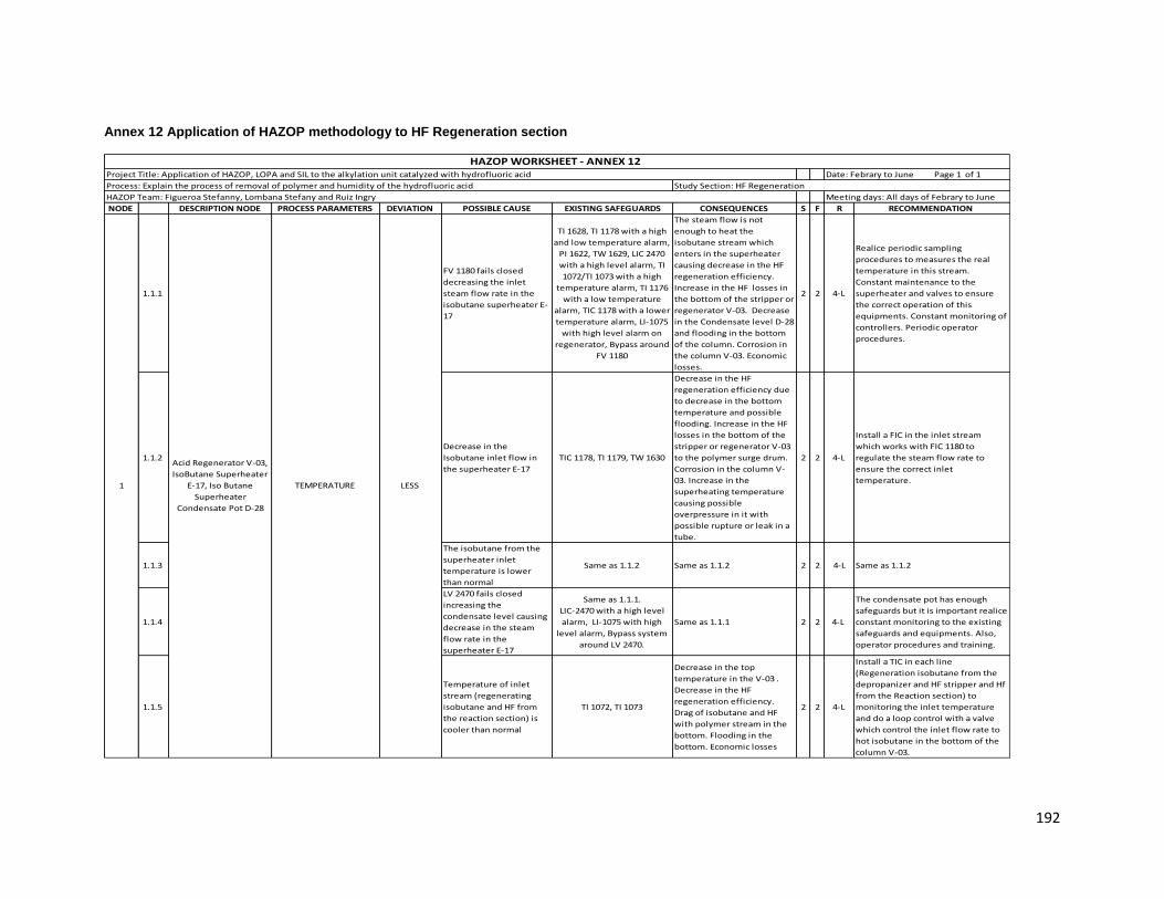
192
Annex 12 Application of HAZOP methodology to HF Regeneration section
NODE DESCRIPTION NODE PROCESS PARAMETERS DEVIATION POSSIBLE CAUSE EXISTING SAFEGUARDS CONSEQUENCES S F R RECOMMENDATION
1.1.1
FV 1180 fails closed
decreasing the inlet
steam flow rate in the
isobutane superheater E-
17
TI 1628, TI 1178 with a high
and low temperature alarm,
PI 1622, TW 1629, LIC 2470
with a high level alarm, TI
1072/TI 1073 with a high
temperature alarm, TI 1176
with a low temperature
alarm, TIC 1178 with a lower
temperature alarm, LI-1075
with high level alarm on
regenerator, Bypass around
FV 1180
The steam flow is not
enough to heat the
isobutane stream which
enters in the superheater
causing decrease in the HF
regeneration efficiency.
Increase in the HF losses in
the bottom of the stripper or
regenerator V-03. Decrease
in the Condensate level D-28
and flooding in the bottom
of the column. Corrosion in
the column V-03. Economic
losses.
2 2 4-L
Realice periodic sampling
procedures to measures the real
temperature in this stream.
Constant maintenance to the
superheater and valves to ensure
the correct operation of this
equipments. Constant monitoring of
controllers. Periodic operator
procedures.
1.1.2
Decrease in the
Isobutane inlet flow in
the superheater E-17
TIC 1178, TI 1179, TW 1630
Decrease in the HF
regeneration efficiency due
to decrease in the bottom
temperature and possible
flooding. Increase in the HF
losses in the bottom of the
stripper or regenerator V-03
to the polymer surge drum.
Corrosion in the column V-
03. Increase in the
superheating temperature
causing possible
overpressure in it with
possible rupture or leak in a
tube.
2 2 4-L
Install a FIC in the inlet stream
which works with FIC 1180 to
regulate the steam flow rate to
ensure the correct inlet
temperature.
1.1.3
The isobutane from the
superheater inlet
temperature is lower
than normal
Same as 1.1.2 Same as 1.1.2 2 2 4-L Same as 1.1.2
1.1.4
LV 2470 fails closed
increasing the
condensate level causing
decrease in the steam
flow rate in the
superheater E-17
Same as 1.1.1.
LIC-2470 with a high level
alarm, LI-1075 with high
level alarm, Bypass system
around LV 2470.
Same as 1.1.1 2 2 4-L
The condensate pot has enough
safeguards but it is important realice
constant monitoring to the existing
safeguards and equipments. Also,
operator procedures and training.
1.1.5
Temperature of inlet
stream (regenerating
isobutane and HF from
the reaction section) is
cooler than normal
TI 1072, TI 1073
Decrease in the top
temperature in the V-03 .
Decrease in the HF
regeneration efficiency.
Drag of isobutane and HF
with polymer stream in the
bottom. Flooding in the
bottom. Economic losses
2 2 4-L
Install a TIC in each line
(Regeneration isobutane from the
depropanizer and HF stripper and Hf
from the Reaction section) to
monitoring the inlet temperature
and do a loop control with a valve
which control the inlet flow rate to
hot isobutane in the bottom of the
column V-03.
HAZOP Team: Figueroa Stefanny, Lombana Stefany and Ruiz Ingry Meeting days: All days of Febrary to June
LESS TEMPERATURE
Acid Regenerator V-03,
IsoButane Superheater
E-17, Iso Butane
Superheater
Condensate Pot D-28
1
HAZOP WORKSHEET - ANNEX 12 Project Title: Application of HAZOP, LOPA and SIL to the alkylation unit catalyzed with hydrofluoric acid Date: Febrary to June Page 1 of 1
Process: Explain the process of removal of polymer and humidity of the hydrofluoric acid Study Section: HF Regeneration

193
NODE DESCRIPTION NODE PROCESS PARAMETERS DEVIATION POSSIBLE CAUSE EXISTING SAFEGUARDS CONSEQUENCES S F R RECOMMENDATION
1.1.6 TV 1168 fails opened
TI 1176 with low
temperature alarm, LI 1075
with high level alarm on
regenerator, TI 1072 and TI-
1073 with high temperature
alarm, TIC 1178 with low
temperature alarm, Hand
wheel on TV 1168.
Increase in the inlet flow
rate to the V-03 causing
flooding in the one plate.
More reflux leading to
column flooding. Potential
for colder operation in the
bottom of the regenerator
and flooding. Potential for
corrosion in the column and
loss of acid to the polymer
surge drum.
2 2 4-L
Change the ubication of the existing
FI in the line after valve TV1168.
Periodic monitoring of this indicator
for part of operator.
1.1.7 FV 1171 fails opened Same as 1.1.6
Increase in the inlet flow
rate to the V-03 causing
flooding in the five plate.
Potential for colder
operation in the bottom of
the regenerator and
flooding. Potential for
corrosion in the column and
loss of acid to the polymer
surge drum.
2 2 4-L
Install a manual valve and FI in the
line from ALKAD regeneration
section and close the intermittent
flow. Periodic maintenance to valve
FV 1171 and the existing safeguards.
1.1.8
Wrong operation of
superheater E-17
decreasing the heat
transfer
LIC2470, PI1622, TI1628,
TIC1178Same as 1.1.2 2 2 4-L Same as 1.1.1
1.1.9 Operational problems in
the condenser D-28 Same as 1.1.4 Same as 1.1.1 2 2 4-L Same as 1.1.4
1.2.1 HIGH
FV 1180 fails opened
increasing the inlet
steam flow rate in the
isobutane superheater E-
17
Same as 1.1.1
Inefficient use of steam.
Higher corrosion in the
column V-03. Drag of
pollutants to isostripper
section. Increase in the
pollutants in the product
stream. Increase the level in
the condensate pot causing
overpressure and possible
explosion. Economic losses.
3 2 6-M
This line counts with the enough
loop controls, controllers and
indicators but it is important relice
constant monitoring to the
operating variables and
maintenance to the equipments and
existing safeguards. Also, operator
procedures and training
LESS
HAZOP Team: Figueroa Stefanny, Lombana Stefany and Ruiz Ingry Meeting days: All days of Febrary to June
TEMPERATURE
Acid Regenerator V-03,
IsoButane Superheater
E-17, Iso Butane
Superheater
Condensate Pot D-28
1
HAZOP WORKSHEET - ANNEX 12 Project Title: Application of HAZOP, LOPA and SIL to the alkylation unit catalyzed with hydrofluoric acid Date: Febrary to June Page 1 of 1
Process: Explain the process of removal of polymer and humidity of the hydrofluoric acid Study Section: HF Regeneration

194
NODE DESCRIPTION NODE PROCESS PARAMETERS DEVIATION POSSIBLE CAUSE EXISTING SAFEGUARDS CONSEQUENCES S F R RECOMMENDATION
1.2.2 FV 1171 fails closed
Intermittent flow from
ALKAD section, Lab
sampling, hand wheel on FV
1171, TIC 1168 which will
add reflux to maintain the
overhead temperature of
the regenerator.
Decrease in the HF inlet flow
rate decreasing the
remotion of soluble
pollutants in the acid. For a
short period of time, there
are no significant
consequences. For a longer
period of time, potential for
hotter overhead
temperature in the
regenerator. Loss of acid
purity resulting in acid
runaway. Potential for
corrosion, leaks, and
personnel injury. Losses in
the acid purity. Increase in
the production of organics
fluorides and polimerization
4 3 12-S
Install a FIC in the inlet line of the
regenerator V-03 (after valve FV
1171) which works with a flow valve
in the intermittent flow line to
increase the flow rate in case of this
valve or FIC 1171 which regulate the
valve fails and mantein the
operational range (626 BDP). Verify
sampling schedule and frequency
for isobutane and Olefin Feed.
Consider adding an HF / Water acid
analyzer on the E-28/E28A reactor
acid circulation loop. Create a
calculation in PCS for the V-03 acid
regenerator Isobutane and acid
ratio.
1.2.3
The isobutane from the
superheater inlet
temperature is higher
than normal
Same as 1.1.1 Same as 1.2.1 3 2 6-M Same as 1.2.1
1.2.4 TV 1168 malfunctions
closed
FI-1170 flow indication.
TI-1625 temperature
indication.
Hand wheel on TV-1168.
Decrease in the isobutane
from the depropanizer and
HF stripper section. Higher
corrosion in the column V-
03. Drag of pollutants to
isostripper section.Loss of
Regenerator reflux resulting
in higher overhead
temperatures. Potential for
higher corrosion in the acid
regenerator. Over a longer
period of time, potential for
increased impurities in the
acid. Over time, potential for
acid runaway.
4 3 12-S
Install a higher temperature alarm in
the line. Constant monitoring to the
temperature in the control room.
Periodic maintenance to the
controllers (adjust the set point) and
valves to avoid this kind of problems
in the plant.
1.2.5
Temperature of inlet
stream (regenerating
isobutane and Hf from
the reaction section) is
higher than normal
Same as 1.1.5
Increase in the top
temperature in the V-03.
Higher corrosion in the
column V-03. Drag of
pollutants to isostripper
section. Increase in the
pollutants in the product
stream.
2 2 4-L Same as 1.1.5
HIGH TEMPERATURE
Acid Regenerator V-03,
IsoButane Superheater
E-17, Iso Butane
Superheater
Condensate Pot D-28
1
HAZOP Team: Figueroa Stefanny, Lombana Stefany and Ruiz Ingry Meeting days: All days of Febrary to June
HAZOP WORKSHEET - ANNEX 12 Project Title: Application of HAZOP, LOPA and SIL to the alkylation unit catalyzed with hydrofluoric acid Date: Febrary to June Page 1 of 1
Process: Explain the process of removal of polymer and humidity of the hydrofluoric acid Study Section: HF Regeneration

195
NODE DESCRIPTION NODE PROCESS PARAMETERS DEVIATION POSSIBLE CAUSE EXISTING SAFEGUARDS CONSEQUENCES S F R RECOMMENDATION
1.3.1
Rupture in some (inlet or
outlet) pipes to the
regenerator V-03
FIC 1171, FI 1170, PI 1622
Possible fire explosion for
hydrocarbon spill. Air
pollution
Injuries to the employees
for acid spill (possible died
of employees if one of them
are exposure to high
concentration). Equipment
damage Economic
losses. Stop and complete
evacuation of the unit.
4 2 8-M
Periodic maintenance to the pipes.
Install a FI in the outlet pipe in the
bottom of the regenerator. If it is
possible install a FI in the inlet pipe
(in the bottom of the tower).
1.3.2
Manual valve GBCF22 in
the top of the
regenerator is open
No safeguards Same as 1.3.1 4 3 12-S
Change this valve for a security
valve (PSV) in the top of the column
with a bypass system and send the
stream to flare header and reduce
the risk for the employees to
contaminate with HF.
1.3.3
Decrease in the tower
temperature due to
cause above analyzed
TI 1073/TI 1072 with a high
temperature alarm, TI 1176
with a low temperature
alarm, TIC 1168
Decrease in the HF
regeneration efficiency.
Increase in the HF losses in
the bottom of the stripper or
regenerator V-03. decrease
in the Condensate level D-28
and flooding in the bottom
of the column. Corrosion in
the column V-03. Economic
losses.
2 2 4-L
Periodic monitoring to the
temperature and analyze all the
recommendation that the team
analyze in the less temperature.
1.3.4
PSV 1988 fails open
decreasing the inlet flow
of hot isobutane in the
bottom
Manual valves GBCF13,
GACF04. Same as 1.1.1 Same as 1.1.1 2 2 4-L Same as 1.1.1
1.3.5
Decrease in the partial
pressure of each
compounds
No safeguards
Increase in the pollutants
vaporization. Decrease of
acid losses but decrease the
remotion of pollutants.
2 4 8-M
Install a pressure indicator in the top
of the column and do constant
monitoring to this parameter.
1.3.6
Increase in the
isobutane/HF acid ratio
causing a decrease in the
partial pressure of other
compounds
No safeguards Same as 1.3.5 2 4 8-M
Install a pressure indicator in the top
of the column and do constant
monitoring to this parameter.
Acid Regenerator V-03,
IsoButane Superheater
E-17, Iso Butane
Superheater
Condensate Pot D-28
1 PRESSURE
HAZOP Team: Figueroa Stefanny, Lombana Stefany and Ruiz Ingry Meeting days: All days of Febrary to June
HAZOP WORKSHEET - ANNEX 12 Project Title: Application of HAZOP, LOPA and SIL to the alkylation unit catalyzed with hydrofluoric acid Date: Febrary to June Page 1 of 1
Process: Explain the process of removal of polymer and humidity of the hydrofluoric acid Study Section: HF Regeneration
LESS

196
NODE DESCRIPTION NODE PROCESS PARAMETERS DEVIATION POSSIBLE CAUSE EXISTING SAFEGUARDS CONSEQUENCES S F R RECOMMENDATION
1.4.1
Decrease in the
isobutane/HF acid ratio
causing a increase in
partial pressure of other
compounds
No safeguards
Decrease in the pollutants
vaporization. Drag of acid in
the outlet bottom stream.
Increase in the remotion of
pollutants in the bottom of
the tower. Economic losses
2 4 8-M
Install a pressure indicator in the
regenerator to control and
monitoring this parameter.
1.4.2
Increase in partial
pressure of each
compounds
No safeguards Same as 1.4.1 2 4 8-M Same as 1.4.1
1.4.3 Increase in the
regenerator temperature Same as 1.1.1
The increase in the tower
temperature can has a lot of
consequences but those
depends of what is the cause
of this deviation in the
process, due to this
parameter and deviation
were analayze before see
the possible consequences
which stay above.
2 2 4-LSee the recomendations for the
HIGH TEMPERATURE
1.4.4
Tamponade in the exit
line of the superheater
(hot isobutane stripping
stream)
PSV 1988
Potential overpressure in
the superheater causing
possible rupture or leak in
the tube, contamination of
condensate and presence of
hydrocarbon in the
condensate pot, Damage in
equipment due to corrosion
due to potential for leak of
steam into the process.
2 2 4-L
Periodic operator procedures and
training. Periodic maintenance to
security valve and monitoring of the
set point. In the same way
monitoring and maintenance to
condensate pot.
1.4.5 Decrease in the inlet flow
rate to the regenerator
TV 1168, FV 1171, Reflux
stream
Increase in the temperature
in the tower causing higher
corrosion in the V-03. Drag of
pollutants to isostripper
section. Increase in the
pollutants in the product
stream. Increase the level in
the condensate pot causing
overpressure and possible
explosion. Economic losses.
3 3 9-M See the recomendations for the
HIGH TEMPERATURE
1.4.6 Flooding in the bottom of
the tower
LI 1075 with high and lower
level alarm
Drag of pollutants to
isostripper section. Increase
in the pollutants in the
product stream. HF losses in
the bottom. Wrong
operation of the tower,
superheater E-17 and
condensate pot.
3 2 6-M
Periodic monitoring of the level
indicator and the equipments
including the indicators and vessels.
Acid Regenerator V-03,
IsoButane Superheater
E-17, Iso Butane
Superheater
Condensate Pot D-28
1 PRESSURE
HAZOP Team: Figueroa Stefanny, Lombana Stefany and Ruiz Ingry Meeting days: All days of Febrary to June
HAZOP WORKSHEET - ANNEX 12 Project Title: Application of HAZOP, LOPA and SIL to the alkylation unit catalyzed with hydrofluoric acid Date: Febrary to June Page 1 of 1
Process: Explain the process of removal of polymer and humidity of the hydrofluoric acid Study Section: HF Regeneration
HIGH

197
NODE DESCRIPTION NODE PROCESS PARAMETERS DEVIATION POSSIBLE CAUSE EXISTING SAFEGUARDS CONSEQUENCES S F R RECOMMENDATION
1.5.1
LI 1075 fails sending a
wrong signal to the
control room
TI 1176 with a low
temperature alarm, TI
1072/1073 with high
temperature alarm, LT 1075
which is not exposure to
the fluid.
Draining the column than
needed leading to potential
mechanical damage in the
equipment. Shutdown the
unit to repair the damage.
Economic losses
3 2 6-M Maintenance to the LI 1075, operator
training to avoid human error.
1.5.2
Decrease the inlet flow
rate to the regenerator
decreasing the level in
the regenerator bottom
FIC 1171, FI 1170, PI 1622, LI
1075 with high and lower
level alarm
Same as 1.4.5 3 2 6-MSee the recomendations for the
HIGH TEMPERATURE
1.5.3 Manual valve LBNF01 is
closed
LI 1075 with high and lower
level alarmSame as 1.4.5 3 3 9-M
Periodic operator procedures and
training. Periodic maintenance to
manual valve.
1.5.4
Increase in the heat
transfer in the
superheater E-17
increasing the isobutane
stripping temperature
which inlet in the column
Same as 1.1.1 Same as 1.2.1 3 2 6-M Same as 1.2.1
1.5.5 TV 1168 fails closed Same as 1.5.3 Same 1.4.5 3 3 9-M
Maintenance to the loop controls
and valves with the objective to
avoid this kind of errors in the unit
1.6.1 Tamponade in the outlet
line
LI 1075 with high and lower
level alarm
Flooding in the bottom.
Tamponade in the inlet
stream from the superheater
causing overpressure in the
line with possible rupture or
leak in it. Bad compounds
separation for the wrong
tower operation.
2 3 6-M
Maintenance to the indicators LI
1075 and realize periodic operator
procedures and training
1.6.2 TV 1168 fails opened Same as 1.1.6 Same as 1.1.6 1 2 2-L Same as 1.1.6
1.6.3
Decrease in the inlet
temperature from the
superheater due to a bad
heat transfer
Same as 1.1.2 Same as 1.1.2 2 2 4-L Same as 1.1.2
1.6.4Increase in the inlet flow
to the regenerator
GBCF22, TI1072, TI1073, LI
1075 with high and lower
level alarm
The stream of hot isobutane
is not enough to separate
the compounds causing HF
losses in the bottom and
drag of pollutant to
isostripper section. Wrong
operation of the tower,
superheater E-17 and
condensate pot.
3 2 6-M Same as 1.3.1
LEVEL
HIGH
Acid Regenerator V-03,
IsoButane Superheater
E-17, Iso Butane
Superheater
Condensate Pot D-28
1
HAZOP Team: Figueroa Stefanny, Lombana Stefany and Ruiz Ingry Meeting days: All days of Febrary to June
HAZOP WORKSHEET - ANNEX 12 Project Title: Application of HAZOP, LOPA and SIL to the alkylation unit catalyzed with hydrofluoric acid Date: Febrary to June Page 1 of 1
Process: Explain the process of removal of polymer and humidity of the hydrofluoric acid Study Section: HF Regeneration
LESS

198
NODE DESCRIPTION NODE PROCESS PARAMETERS DEVIATION POSSIBLE CAUSE EXISTING SAFEGUARDS CONSEQUENCES S F R RECOMMENDATION
1.6.5 HIGH
LI 1075 fails sending a
wrong signal to the
control room
Heat tracing on the bottom
of the piping, Procedures to
flush the bottom line after
every
dump, TI 1072 and TI 1073
with high temperature
alarm, Design of the LT is
nuclear and external to the
vessel (no fluid exposure).
Operator does not dump
when needed due to bad LI
reading. Higher level with
potential to flood. Potential
to shutdown the regenerator
and the Alky unit, if plug is
not removed in short time.
3 3 9-M Same as 1.5.1
1.7.1 NO Same as less Same as less Same as less Same as less
2.1.1 Decrease in the steam
inlet temperature
TI 1184/1185/1186/1187 is
located in the liquid level
Potential polymer set up in
the vessel. Delay in transfer
the polymer neutralizer
drum D-17.
2 2 4-L
Consider install a temperature
indicator in the inlet pipe (steam
line and polymer from V-03 line) to
monitoring this variable, If it is
possible install a temperature valve
in the steam line which works with a
TIC located in the polymer from V-03
line to regulate the steam flow.
2.1.2
Manual valve LWCS01 is
closed decreasing the
steam inlet flow rate
Same as 2.1.1 Same as 2.1.1 2 2 4-L
Replace the manual valve LWCS01
for a temperature valve controlled
by TIC to avoid human errors
2.1.3
The polymer stream from
V-03 is cooler than
normal
Same as 2.1.1. Clamp-on
steam jacket Same as 2.1.1 2 2 4-L Same as 2.1.1
2.1.4 Increase in the inlet flow
rate from V-03
TI 1184/1185/1186/1187,
PSV 1183
Increase the level in the
drum causing potential fire
for overpressure and injuries
to employees and
sourronding areas
4 2 8-M Same as 2.1.1
2.2.1 Increase the low pressure
steam inlet temperature Same as 2.1.1
The residence time in the
drum is more than normal
due the increase in solubility
of the azeotrope. Inefficient
use of steam
3 2 6-M Same as 2.1.1
2.2.2 Manual valve LWCS01
fails opened Same as 2.1.4 Same as 2.2.1. 3 2 6-M Same as 2.1.2
2.2.3 Decrease in the inlet flow
rate to the regeneratorSame as 2.1.4
Drag to acid and traces of
polymer to flare header
causing air pollutions and
potential injuries to
employees and citizens.
4 2 8-M Same as 2.1.1
LEVEL
Acid Regenerator V-03,
IsoButane Superheater
E-17, Iso Butane
Superheater
Condensate Pot D-28
1
2POLYMER SURGE DRUM
D-16
HAZOP Team: Figueroa Stefanny, Lombana Stefany and Ruiz Ingry Meeting days: All days of Febrary to June
HAZOP WORKSHEET - ANNEX 12 Project Title: Application of HAZOP, LOPA and SIL to the alkylation unit catalyzed with hydrofluoric acid Date: Febrary to June Page 1 of 1
Process: Explain the process of removal of polymer and humidity of the hydrofluoric acid Study Section: HF Regeneration
HIGH
TEMPERATURE
LESS
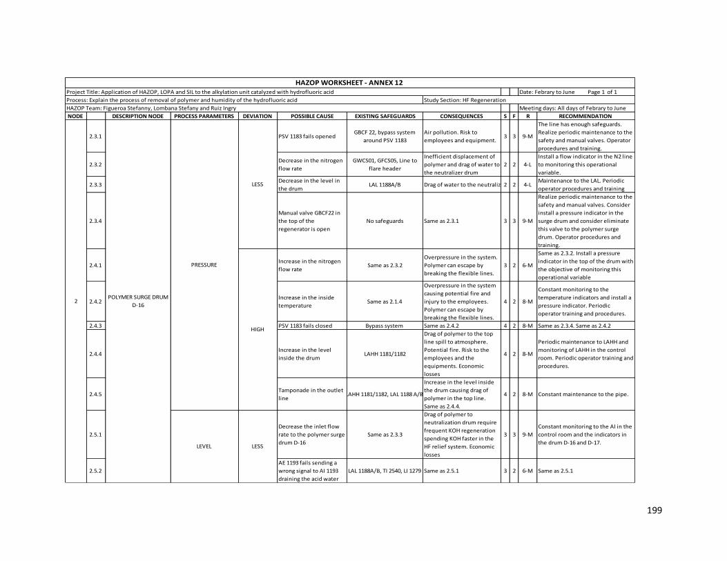
199
NODE DESCRIPTION NODE PROCESS PARAMETERS DEVIATION POSSIBLE CAUSE EXISTING SAFEGUARDS CONSEQUENCES S F R RECOMMENDATION
2.3.1 PSV 1183 fails opened GBCF 22, bypass system
around PSV 1183
Air pollution. Risk to
employees and equipment. 3 3 9-M
The line has enough safeguards.
Realize periodic maintenance to the
safety and manual valves. Operator
procedures and training.
2.3.2 Decrease in the nitrogen
flow rate
GWCS01, GFCS05, Line to
flare header
Inefficient displacement of
polymer and drag of water to
the neutralizer drum
2 2 4-L
Install a flow indicator in the N2 line
to monitoring this operational
variable.
2.3.3 Decrease in the level in
the drum LAL 1188A/B Drag of water to the neutralizer drum 2 2 4-L
Maintenance to the LAL. Periodic
operator procedures and training
2.3.4
Manual valve GBCF22 in
the top of the
regenerator is open
No safeguards Same as 2.3.1 3 3 9-M
Realize periodic maintenance to the
safety and manual valves. Consider
install a pressure indicator in the
surge drum and consider eliminate
this valve to the polymer surge
drum. Operator procedures and
training.
2.4.1 Increase in the nitrogen
flow rate Same as 2.3.2
Overpressure in the system.
Polymer can escape by
breaking the flexible lines.
3 2 6-M
Same as 2.3.2. Install a pressure
indicator in the top of the drum with
the objective of monitoring this
operational variable
2.4.2 Increase in the inside
temperature Same as 2.1.4
Overpressure in the system
causing potential fire and
injury to the employees.
Polymer can escape by
breaking the flexible lines.
4 2 8-M
Constant monitoring to the
temperature indicators and install a
pressure indicator. Periodic
operator training and procedures.
2.4.3 PSV 1183 fails closed Bypass system Same as 2.4.2 4 2 8-M Same as 2.3.4. Same as 2.4.2
2.4.4 Increase in the level
inside the drum LAHH 1181/1182
Drag of polymer to the top
line spill to atmosphere.
Potential fire. Risk to the
employees and the
equipments. Economic
losses
4 2 8-M
Periodic maintenance to LAHH and
monitoring of LAHH in the control
room. Periodic operator training and
procedures.
2.4.5 Tamponade in the outlet
lineLAHH 1181/1182, LAL 1188 A/B
Increase in the level inside
the drum causing drag of
polymer in the top line.
Same as 2.4.4.
4 2 8-M Constant maintenance to the pipe.
2.5.1
Decrease the inlet flow
rate to the polymer surge
drum D-16
Same as 2.3.3
Drag of polymer to
neutralization drum require
frequent KOH regeneration
spending KOH faster in the
HF relief system. Economic
losses
3 3 9-M
Constant monitoring to the AI in the
control room and the indicators in
the drum D-16 and D-17.
2.5.2
AE 1193 fails sending a
wrong signal to AI 1193
draining the acid water
LAL 1188A/B, TI 2540, LI 1279 Same as 2.5.1 3 2 6-M Same as 2.5.1
POLYMER SURGE DRUM
D-16
LEVEL
2
HAZOP Team: Figueroa Stefanny, Lombana Stefany and Ruiz Ingry Meeting days: All days of Febrary to June
HAZOP WORKSHEET - ANNEX 12 Project Title: Application of HAZOP, LOPA and SIL to the alkylation unit catalyzed with hydrofluoric acid Date: Febrary to June Page 1 of 1
Process: Explain the process of removal of polymer and humidity of the hydrofluoric acid Study Section: HF Regeneration
PRESSURE
LESS
HIGH
LESS

200
NODE DESCRIPTION NODE PROCESS PARAMETERS DEVIATION POSSIBLE CAUSE EXISTING SAFEGUARDS CONSEQUENCES S F R RECOMMENDATION
2.6.1
Increase in the inlet flow
rate from the regenerator
V-03
GBCF 22
Drag of polymer to the
nitrogen and PSV inlet
piping. Polymer spill with
potential fire and personnel
injury. Possible explosion.
4 2 8-M
Install a flow indicator in the inlet
line from regenerator V-03 to
monitoring this operational
variable.
2.6.2 Tamponade in the
draining lines Same as 2.4.5
Decrease the level polymer
neutralizer D-17. Same as
2.6.1
4 2 8-M
Periodic maintenance to the pipe
and do a schedule to realize this
action. Periodic operator training
and procedures
2.6.3 Increase the flow rate
from D-101 GDNF01
Drag of polymer to the
nitrogen and PSV inlet
piping. Polymer spill with
potential fire and personnel
injury.
3 3 9-M
Install a flow indicator control in the
line from D-101 with a flow valve to
control the inlet flow from the alkad
section D-101
2.7.1 NO Same as less Same as less Same as less Same as less
3.1.1
Decrease in the low
pressure steam inlet
temperature
TI 1196
Potential polymer set up in
the vessel. Delay in transfer
to the polymer neutralizer
drum or the regenerator V-
03
2 2 4-L
Consider install a temperature
indicator in the inlet pipe to
monitoring this operational
variable, If it is possible install a
temperature valve in the steam line
which works with a TIC to regulate
the steam flow.
3.1.2 Manual valve LWCS01
fails closed Same as 3.1.1 Same as 3.1.1 2 2 4-L
Install a temperature valve
controled by TIC to avoid human
errors
3.1.3
The polymer stream from
D-16 is cooler than
normal
Same as 3.1.1. Clamp-on
steam jacket Same as 3.1.1 2 2 4-L Same as 3.1.1
3.1.4 Increase in the inlet flow
rate LG 1195/1197, TI 1196
Increase the level in the
drum causing potential fire
for overpressure and injuries
to employees
4 2 8-M Same as 3.1.1
3.1.5 Decrease in the steam
inlet flow rateTI 1196 Same as 3.1.1 2 3 6-M Same as 3.1.1
3.2.1 HIGHPresence of acid water in
the drum
TI 1196, Drain the water
from polymer surge drum
after the acid regenerator
dump
The KOH reacts with the acid
water approaching to the
design temperature.
Possible overpressure in the
drum with potential fire and
spill of polymer and traces of
HF and KOH to atmosphere.
Potential personnel injury
into the plant and
sourronding areas .
3 2 6-M
Control and constant monitoring to
the draining system. Maintenance to
the temperature indicator to
prevent the wrong signal to the
control room. Personnel training
and constant procedures.
TEMPERATURE POLYMER NEUTRALIZER
D-17 3
LEVEL POLYMER SURGE DRUM
D-16 2
HAZOP Team: Figueroa Stefanny, Lombana Stefany and Ruiz Ingry Meeting days: All days of Febrary to June
HAZOP WORKSHEET - ANNEX 12 Project Title: Application of HAZOP, LOPA and SIL to the alkylation unit catalyzed with hydrofluoric acid Date: Febrary to June Page 1 of 1
Process: Explain the process of removal of polymer and humidity of the hydrofluoric acid Study Section: HF Regeneration
HIGH
LESS

201
NODE DESCRIPTION NODE PROCESS PARAMETERS DEVIATION POSSIBLE CAUSE EXISTING SAFEGUARDS CONSEQUENCES S F R RECOMMENDATION
3.2.2Increase the low pressure
steam inlet temperature Same as 3.1.1
The residence time in the
drum is more than normal
due the increase in solubility
of the azeotrope. Inefficient
use of steam
2 2 4-L Same as 3.1.1
3.2.3 Manual valve LWCS01 is
opened TI 1196
Possible overpressure in the
drum with potential fire and
spill of polymer and traces of
HF and KOH to atmosphere.
Potential personnel injury
into the plant and
sourronding areas.
2 3 6-M Same as 3.1.2
3.2.4
Increase in the steam
flow rate to the camp on
jacket
Same as 3.2.3 Same as 3.2.3 3 3 9-M Same as 3.1.2
3.2.5
Decrease in the inlet flow
rate to the neutralizer D-
17 from D-16
Reflux stream, stream from
S-05. Same as 3.2.3
Inefficient use of steam and
KOH. Same as 3.2.3 4 2 8-M Same as 3.1.1
3.3.1 PSV 1194 fails opened GACF04Air pollution. Risk to
employees and equipment. 3 2 6-M
The line has enough safeguards.
Realize periodic maintenance to the
safety and manual valves. Operator
procedures and training.
3.3.2 Decrease in the nitrogen
flow rate
GWCS04, GFCS05, LFCS04,
Line to flare header
Inefficient displacement of
polymer to closed drain
drum
2 2 4-L
Install a flow indicator in nitrogen
line to monitoring this operational
variable.
3.3.3 Decrease in the level in
the polymer neutralizer LG 1195/1197
No displacemento to the the
closed drain drum. Potential
corrosion
2 2 4-LMaintenance to the LG. Periodic
operator procedures and training
3.3.4
Manual valve GWCS07 in
the top of the vessel is
open
No safeguards Same as 3.3.1 3 3 9-M
Realize periodic maintenance to the
safety and manual valves. Operator
procedures and training. Consider if
it is necessary this manual valve in
the vessel.
3.4.1 Increase in the nitrogen
flow rate Same as 3.3.2
Overpressure in the system.
Polymer can escape by
breaking the flexible lines.
3 2 6-M
Same as 3.3.2. Install a pressure
indicator in the top of the drum with
the objective of monitoring this
operational variable
3.4.2 Increase in the inside
temperature TI 1196
Overpressure in the system
causing potential fire and
injury to the employees.
Polymer can escape by
breaking the flexible lines.
4 2 8-M
Constant monitoring to the
temperature indicator and install a
pressure indicator. Periodic
operator training and procedures.
3.4.3 PSV 1183 fails closed Bypass system around valve
PSV 1183, GWCS07Same as 3.4.2 4 1 4-L Same as 3.3.4. Same as 3.4.2
POLYMER NEUTRALIZER
D-17 3
PRESSURE
HIGHTEMPERATURE
HAZOP Team: Figueroa Stefanny, Lombana Stefany and Ruiz Ingry Meeting days: All days of Febrary to June
HAZOP WORKSHEET - ANNEX 12 Project Title: Application of HAZOP, LOPA and SIL to the alkylation unit catalyzed with hydrofluoric acid Date: Febrary to June Page 1 of 1
Process: Explain the process of removal of polymer and humidity of the hydrofluoric acid Study Section: HF Regeneration
HIGH
LESS
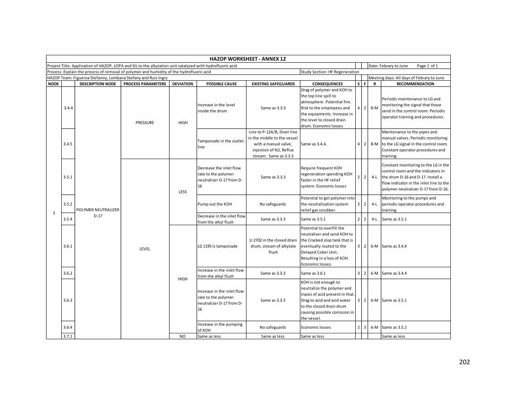
202
NODE DESCRIPTION NODE PROCESS PARAMETERS DEVIATION POSSIBLE CAUSE EXISTING SAFEGUARDS CONSEQUENCES S F R RECOMMENDATION
3.4.4Increase in the level
inside the drum Same as 3.3.3
Drag of polymer and KOH to
the top line spill to
atmosphere. Potential fire.
Risk to the employees and
the equipments. Increase in
the level to closed drain
drum. Economic losses
4 2 8-M
Periodic maintenance to LG and
monitoring the signal that those
send in the control room. Periodic
operator training and procedures.
3.4.5 Tamponade in the outlet
line
Line to P-12A/B, Drain line
in the middle to the vessel
with a manual valve,
injection of N2, Reflux
stream. Same as 3.3.3
Same as 3.4.4. 4 2 8-M
Maintenance to the pipes and
manual valves. Periodic monitoring
to the LG signal in the control room.
Constant operator procedures and
training.
3.5.1
Decrease the inlet flow
rate to the polymer
neutralizer D-17 from D-
16
Same as 3.3.3
Require frequent KOH
regeneration spending KOH
faster in the HF relief
system. Economic losses
2 2 4-L
Constant monitoring to the LG in the
control room and the indicators in
the drum D-16 and D-17. Install a
flow indicator in the inlet line to the
polymer neutralizer D-17 from D-16.
3.5.2 Pump out the KOH No safeguards
Potential to get polymer into
the neutralization system
relief gas scrubber.
2 2 4-L
Monitoring to the pumps and
periodic operator procedures and
training
3.5.4 Decrease in the inlet flow
from the alkyl flush Same as 3.3.3 Same as 3.5.1 2 2 4-L Same as 3.5.1
3.6.1 LG 1195 is tamponade
LI 2702 in the closed drain
drum, stream of alkylate
flush
Potential to overfill the
neutralizer and send KOH to
the Cracked slop tank that is
eventually routed to the
Delayed Coker Unit.
Resulting in a loss of KOH.
Economic losses.
3 2 6-M Same as 3.4.4
3.6.2 Increase in the inlet flow
from the alkyl flush Same as 3.3.3 Same as 3.6.1 3 2 6-M Same as 3.4.4
3.6.3
Increase in the inlet flow
rate to the polymer
neutralizer D-17 from D-
16
Same as 3.3.3
KOH is not enough to
neutralize the polymer and
traces of acid present in that.
Drag to acid and acid water
to the closed drain drum
causing possible corrosion in
the vessel.
3 2 6-M Same as 3.5.1
3.6.4 Increase in the pumping
of KOHNo safeguards Economic losses 2 3 6-M Same as 3.5.2
3.7.1 NO Same as less Same as less Same as less Same as less
PRESSURE
HAZOP Team: Figueroa Stefanny, Lombana Stefany and Ruiz Ingry Meeting days: All days of Febrary to June
HAZOP WORKSHEET - ANNEX 12 Project Title: Application of HAZOP, LOPA and SIL to the alkylation unit catalyzed with hydrofluoric acid Date: Febrary to June Page 1 of 1
Process: Explain the process of removal of polymer and humidity of the hydrofluoric acid Study Section: HF Regeneration
HIGH
LEVEL
LESS
HIGH
POLYMER NEUTRALIZER
D-17 3

203
NODE DESCRIPTION NODE PROCESS PARAMETERS DEVIATION POSSIBLE CAUSE EXISTING SAFEGUARDS CONSEQUENCES S F R RECOMMENDATION
4.1.1
Decrease in the low
pressure steam inlet
temperature
TI 2704 with low
temperature alarm
Potential polymer set up in
the vessel. Potential
mechanical damage in the
pump P-09A/B. Economic
losses
3 2 6-M
Change the TI 2704 for a TIC and
install a temperature valve in the
inlet steam pipe which works with
this controller. Consider install a TI
in the vessel
4.1.2 Manual valve LWCS01
fails closed Same as 4.1.1 Same as 4.1.1 3 2 6-M
Same as 4.1.1. Install a bypass
system in the line
4.1.3 The inlet stream is cooler
than normal
Same as 4.1.1. Clamp-on
steam jacket Same as 4.1.1 3 2 6-M Same as 4.1.1
4.1.4 Increase in the inlet flow
rate
LI 2702 with higher and
lower level alarm, LG 2702.
Same as 4.1.1.
Increase the level in the
drum causing potential fire
for overpressure and injuries
to employees
4 1 4-L Same as 4.1.1
4.1.5Decrease in the steam
inlet flow rateSame as 4.1.1 Same as 4.1.1 3 2 6-M Same as 4.1.1
4.2.1Increase the low pressure
steam inlet temperature Same as 4.1.1
Inefficient use of steam.
Increase the pressure inside
causing potential fire and
personnel injury. Economic
losses
2 2 4-L Same as 4.1.1
4.2.2 Manual valve LWCS01
fails opened Same as 4.1.1 Same as 4.2.1 2 2 4-L Same as 4.1.2
4.2.3 Decrease in the inlet flow
rate Same as 4.1.4 Same as 4.2.1 2 2 4-L Same as 4.1.1
4.2.4
Increase in the steam
flow rate to the camp on
jacket
Same as 4.1.1 Same as 4.2.1 2 2 4-L Same as 4.1.1
4.3.1 Manual valve GACF04 is
open PI 2709
Polymer spill to atmosphere.
Potential fire.
Risk to the employees and
the equipments.
Economic losses.
3 2 6-M
Realize periodic maintenance to
manual valves. Operator procedures
and training.
4.3.2 Decrease in the nitrogen
flow rate
Bypass system, PI 2714, PI
2709
No important consequences
identified. 1 1 1-L
Install a flow indicator in the line to
monitoring this operational
variable.
4.3.3Decrease in the level in
the drum
LI 2702 with high and lower
level alarm, LG2703
NPSH to pump P-09A/B is not
enough. Mechanical damage
to pump.
2 1 2-LMaintenance to the LI. Periodic
operator procedures and training
4.3.4
Manual valve GWCS03 in
the top of the vessel is
open
No safeguards Same as 4.3.1 3 3 9-M
Realize periodic maintenance to
manual valve. Operator procedures
and training. Consider if it is
necessary this manual valve in the
vessel. Analyze if this valve can
change for a safety valve.
HAZOP Team: Figueroa Stefanny, Lombana Stefany and Ruiz Ingry Meeting days: All days of Febrary to June
HAZOP WORKSHEET - ANNEX 12 Project Title: Application of HAZOP, LOPA and SIL to the alkylation unit catalyzed with hydrofluoric acid Date: Febrary to June Page 1 of 1
Process: Explain the process of removal of polymer and humidity of the hydrofluoric acid Study Section: HF Regeneration
PRESSURE
CLOSED DRAIN DRUM D-
404 4
TEMPERATURE
LESS
HIGH
LESS
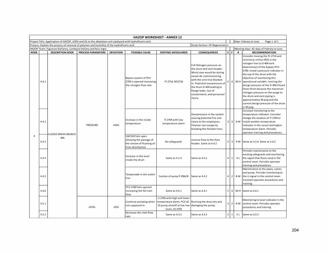
204
NODE DESCRIPTION NODE PROCESS PARAMETERS DEVIATION POSSIBLE CAUSE EXISTING SAFEGUARDS CONSEQUENCES S F R RECOMMENDATION
4.4.1
Bypass system of PCV
2700 is opened increasing
the nitrogen flow rate
PI 2714, RO2716
Full Nitrogen pressure on
the drum and vent header.
Worst case would be during
vessel de-commissioning
with the vent line blocked
in. Potential overpressure of
the drum D-404 leading to
flange leaks, loss of
containment, and personnel
injury.
5 4 20-H
Consider moving the PI-2714 and
restrictive orifice (RO) in the
nitrogen line to D-404 vent
downstream of the bypass PCV-
2700. Install a pressure indicator in
the top of the drum with the
objective of monitoring this
operational variable. revising the
design pressure of the D-404 Closed
Drain Drum because the maximum
nitrogen pressure on the purge to
the drum and vent piping is
approximately 95 psig and the
current design pressure of the drum
is 50 psig.
4.4.2 Increase in the inside
temperature
TI 2704 with low
temperature alarm
Overpressure in the system
causing potential fire and
injury to the employees.
Polymer can escape by
breaking the flexible lines.
3 3 9-M
Constant monitoring to the
temperature indicator. Consider
change the location of TI 2704 or
install another temperature
indicator in the vessel and higher
temperature alarm. Periodic
operator training and procedures.
4.4.3
LWCS03 fails open
allowing the passage of
the stream of flushing oil
from distribution
No safeguards reverse flow to the flare
header. Same as 4.4.2 3 3 9-M Same as 3.3.4. Same as 3.4.2
4.4.4 Increase in the level
inside the drum Same as 4.1.4 Same as 4.4.2 4 1 4-L
Periodic maintenance to the
existing safeguards and monitoring
the signal that those send in the
control room. Periodic operator
training and procedures.
4.4.5 Tamponade in the outlet
lineSuction of pump P-09A/B Same as 4.4.2 4 2 8-M
Maintenance to the pipes, valves
and pump. Periodic monitoring to
the LI signal in the control room.
Constant operator procedures and
training.
4.4.6
PCV 2700 fails opened
increasing the N2 inlet
flow
Same as 4.4.1 Same as 4.4.1 5 4 20-H Same as 4.4.1
4.5.1 Continue pumping when
not supposed to
LI 2702 with high and lower
temperature alarm, PCS UC-
32 pump shutoff at low low
level, LG 2703
Running the drum dry and
damaging the pump. 3 2 6-M
Monitoring to level indicator in the
control room. Periodic operator
procedures and training.
4.5.2 Decrease the inlet flow
rate Same as 4.3.3 Same as 4.3.3 2 1 2-L Same as 4.3.3
PRESSURE
CLOSED DRAIN DRUM D-
404 4
HAZOP Team: Figueroa Stefanny, Lombana Stefany and Ruiz Ingry Meeting days: All days of Febrary to June
HAZOP WORKSHEET - ANNEX 12 Project Title: Application of HAZOP, LOPA and SIL to the alkylation unit catalyzed with hydrofluoric acid Date: Febrary to June Page 1 of 1
Process: Explain the process of removal of polymer and humidity of the hydrofluoric acid Study Section: HF Regeneration
LEVEL
HIGH
LESS

205
NODE DESCRIPTION NODE PROCESS PARAMETERS DEVIATION POSSIBLE CAUSE EXISTING SAFEGUARDS CONSEQUENCES S F R RECOMMENDATION
4.6.1 PCV 2700 fails closed Bypass system, PI 2709
Lose Nitrogen pressure in the
sweep to the drum and to the
flare header. Potential for
reverse flow from the low
pressure flare header to the
drain drum
3 1 3-L
The line has enough safeguards.
Realize periodic maintenance to the
valves and pipes. Operator
procedures and training.
4.6.2 Increase in the inlet flow
from polymer neutralizer
PIC 1662 with a low
pressure alarm, LG 1687,
PALL 1661 low pressure
alarm.
Unable to transfer from the
Polymer Neutralizer and unable
to neutralize the polymer
resulting in a high level in the
polymer surge drum and
eventually shutting down the
acid regenerator. Liquid
entrainment in the fuel gas to
the burners. this could result in
pluggage of the burner tips. Loss
of efficiency of the heaters. Loss
of fuel gas flow to the heater
due to high liquid level or
pluggage of the burner tips
which results in the potential to
cut back on the firing to the
heater resulting in lower
temperatures to the
Isostrippers. Potential to get HF
acid in the Alkylate and
downstream. Potential for
increased corrosive
environment overtime which
could result in leaks in process,
with possible personnel
exposure to HF.
5 2 10-M
Install a flow indicator in the inlet
line from polymer neutralizer to
monitoring this operational
variable.
4.6.3 Tamponade in the
draining pipe
LI 2702 with a high level
alarm, TI 2704 with a low
temperature alarm, LG 2703,
Clamp-on steam jacket.
Same as 4.6.2 5 2 10-M
Constant monitoring to the existing
safeguards in the control room.
Periodic maintenance to the pipes.
Operator procedures and training
4.6.4 Pump P-09A/B stop Same as 4.6.2 Same as 4.6.2 5 2 10-M
Monitoring to the pumps and
periodic operator procedures and
training
4.7.1 NO Same as less Same as less Same as less Same as less
CLOSED DRAIN DRUM D-
404 4
HAZOP Team: Figueroa Stefanny, Lombana Stefany and Ruiz Ingry Meeting days: All days of Febrary to June
HAZOP WORKSHEET - ANNEX 12 Project Title: Application of HAZOP, LOPA and SIL to the alkylation unit catalyzed with hydrofluoric acid Date: Febrary to June Page 1 of 1
Process: Explain the process of removal of polymer and humidity of the hydrofluoric acid Study Section: HF Regeneration
LEVEL HIGH
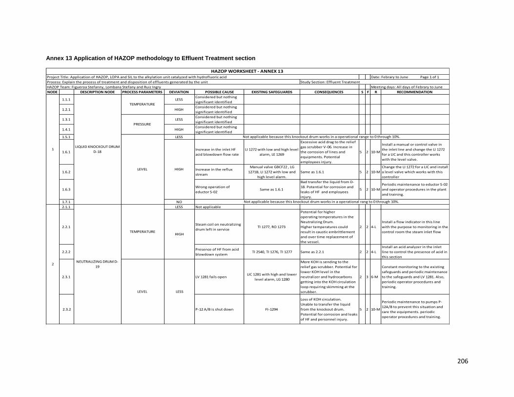
206
Annex 13 Application of HAZOP methodology to Effluent Treatment section
NODE DESCRIPTION NODE PROCESS PARAMETERS DEVIATION POSSIBLE CAUSE EXISTING SAFEGUARDS CONSEQUENCES S F R RECOMMENDATION
1.1.1 LESS Considered but nothing
significant identified
1.2.1 HIGH Considered but nothing
significant identified
1.3.1 LESS Considered but nothing
significant identified
1.4.1 HIGH Considered but nothing
significant identified
1.5.1 LESS
1.6.1 Increase in the inlet HF
acid blowdown flow rate
LI 1272 with low and high level
alarm, LE 1269
Excessive acid drag to the relief
gas scrubber V-06. Increase in
the corrosion of lines and
equipments. Potential
employees injury.
5 2 10-M
Install a manual or control valve in
the inlet line and change the LI 1272
for a LIC and this controller works
with the level valve.
1.6.2 Increase in the reflux
stream
Manual valve GBCF22 , LG
1271B, LI 1272 with low and
high level alarm.
Same as 1.6.1 5 2 10-M
Change the LI 1272 for a LIC and install
a level valve which works with this
controller
1.6.3 Wrong operation of
eductor S-02 Same as 1.6.1
Bad transfer the liquid from D-
18. Potential for corrosion and
leaks of HF and employees
injury.
5 2 10-M
Periodic maintenance to eductor S-02
and operator procedures in the plant
and training.
1.7.1 NO
2.1.1 LESS Not applicable
2.2.1 Steam coil on neutralizing
drum left in serviceTI 1277, RO 1273
Potential for higher
operating temperatures in the
Neutralizing Drum.
Higher temperatures could
result in caustic embrittlement
and over time replacement of
the vessel.
2 2 4-L
Install a flow indicator in this line
with the purpose to monitoring in the
control room the steam inlet flow
2.2.2 Presence of HF from acid
blowdown system TI 2540, TI 1276, TI 1277 Same as 2.2.1 2 2 4-L
Install an acid analyzer in the inlet
line to control the presence of acid in
this section
2.3.1 LV 1281 fails openLIC 1281 with high and lower
level alarm, LG 1280
More KOH is sending to the
relief gas scrubber. Potential for
lower KOH level in the
neutralizer and hydrocarbons
getting into the KOH circulation
loop requiring skimming at the
scrubber.
2 3 6-M
Constant monitoring to the existing
safeguards and periodic maintenance
to the safeguards and LV 1281. Also,
periodic operator procedures and
training.
2.3.2 P-12 A/B is shut down FI-1294
Loss of KOH circulation.
Unable to transfer the liquid
from the knockout drum.
Potential for corrosion and leaks
of HF and personnel injury.
5 2 10-M
Periodic maintenance to pumps P-
12A/B to prevent this situation and
care the equipments. periodic
operator procedures and training.
NEUTRALIZING DRUM D-
192
Not applicable because this knockout drum works in a operational range to 0 through 10%.
HIGH
Not applicable because this knockout drum works in a operational rang to 0 through 10%.
HAZOP WORKSHEET - ANNEX 13 Project Title: Application of HAZOP, LOPA and SIL to the alkylation unit catalyzed with hydrofluoric acid Date: Febrary to June Page 1 of 1
Process: Explain the process of treatment and disposition of effluents generated by the unit Study Section: Effluent Treatment
HAZOP Team: Figueroa Stefanny, Lombana Stefany and Ruiz Ingry Meeting days: All days of Febrary to June
1LIQUID KNOCKOUT DRUM
D-18
TEMPERATURE
PRESSURE
LEVEL
TEMPERATURE HIGH
LESSLEVEL

207
NODE DESCRIPTION NODE PROCESS PARAMETERS DEVIATION POSSIBLE CAUSE EXISTING SAFEGUARDS CONSEQUENCES S F R RECOMMENDATION
2.3.3 P-12 A/B is shut down LI 1279, Intermitent stream
from P-10A, TI 2540
Unable to transfer the acid
water from the polymer surge
drum decreasing the useful life
of the equipment.
2 2 4-L Same as 2.3.2
2.3.4
P-10A pump shuts down or
will not start when needed
(pumping out
Hydrocarbons is a manual
operation).
LI 1279, Intermitent stream
from P-10A
No transfer of hydrocarbon from
neutralizing drum which can
prevent transfer from polymer
surge drum or the liquid from
Knockout drum. Same as 2.3.2
and 2.3.3
2 2 4-L Same as 2.3.2
2.4.1
LV-1281 malfunctions
closed when circulating
KOH solution to the relief
gas scrubber.
LIC 1281 with low and high
level alarm, LG 1280, Bypass
system
Stop the return of KOH to the
relief gas scrubber resulting in
higher level of caustic in the
neutralizer. Potential to get KOH
into the Hydrocarbon section of
the drum. Potential to send KOH
to the waste water treatment
resulting in potential
environmental impact.
2 2 4-L Same as 2.3.1
2.4.2 PI 1275, FI 1294
Increase in the KOH circulation
flow to the eductor. Potential to
build pressure at the eductor
resulting in KOH potentially
going to the polymer surge drum
or the liquid knockout drum and
temporary stopping the transfer
from the surge drum or the
liquid knockout drum.
3 2 6-M
Constant monitoring to check valve in
the rundown line from the surge
drum and liquid knockout drum.
2.4.3 TI 2540, TI 1276
Increase in the KOH circulation
flow with potential for higher
temperatures in the neutralizing
drum.
3 2 6-M Install a high temperature alarm in TI
2540.
2.4.4
Improper setting of the
circulation rate for the KOH
from the P-12 pump (rates
are adjusted by a manual
block/globe valve)
Same as 2.4.1
Potential for higher KOH
levels in the drum with
spillover in the Hydrocarbon
section. Potential to get KOH
into the Hydrocarbon section of
the drum. Potential to send KOH
to the waste water treatment
resulting in potential
environmental
impact
2 2 4-L
Constant monitoring to the existing
safeguards and periodic maintenance
to the safeguards and pump P-12.
Also, periodic operator procedures
and training.
2.5.1 NO Same as less Same as less Same as less Same as less
HAZOP WORKSHEET - ANNEX 13 Project Title: Application of HAZOP, LOPA and SIL to the alkylation unit catalyzed with hydrofluoric acid Date: Febrary to June Page 1 of 1
Process: Explain the process of treatment and disposition of effluents generated by the unit Study Section: Effluent Treatment
HAZOP Team: Figueroa Stefanny, Lombana Stefany and Ruiz Ingry Meeting days: All days of Febrary to June
LESS
LEVEL NEUTRALIZING DRUM D-
192
HIGH
Improper setting of the
circulation rate for the KOH
from the P-12 pump (rates
are adjusted by a manual
block/globe valve)

208
NODE DESCRIPTION NODE PROCESS PARAMETERS DEVIATION POSSIBLE CAUSE EXISTING SAFEGUARDS CONSEQUENCES S F R RECOMMENDATION
3.1.1
Decrease in the inlet
steam flow rate in the
bottom of the scrubber
TI 1287 with high and low
temperature alarm, RO 1284
Traces of acid go out in the top
of the scrubber. 1 1 1-L
Consider install a temperature
indicator control in the vessel which
works with a temperature valve
localized in the inlet steam line to
control the temperature inside.
Periodic monitoring in the control
room and operator procedures and
training.
3.1.2
The temperature of inlet
stream from liquid
knockout drum D-18 is
lower than operational
range
Same as 3.1.1
Same as 3.1.1. Increase in the
use of steam in the process.
Economic losses
1 2 2-L Same as 3.1.1
3.1.3
The temperature of inlet
stream from pumps P-11A
is lower than operational
range
Same as 3.1.1 Same as 3.1.2 1 2 2-L Same as 3.1.1
3.1.4
The temperature of inlet
stream from neutralizing
drum D-19 is lower than
operational range
Same as 3.1.1 Same as 3.1.2 1 2 2-L Same as 3.1.1
3.2.1
Increase in the inlet steam
flow rate in the bottom of
the scrubber
Same as 3.1.1.
Potential for higher operating
temperatures in the Relief Gas
Scrubber. Higher temperatures
(typically greater than 150
degrees F) could result in caustic
embrittlement and over time
replacement of the vessel.
2 2 4-L Same as 3.1.1
3.2.2
The temperature of inlet
stream from liquid
knockout drum D-18 is
higher than operational
range
Same as 3.1.1 Same as 3.2.1 2 2 4-L Same as 3.1.1
3.2.3
The temperature of inlet
stream from pumps P-11A
is higher than operational
range
Same as 3.1.1 Same as 3.2.1 2 2 4-L Same as 3.1.1
3.2.4
The temperature of inlet
stream from neutralizing
drum D-19 is higher than
operational range
Same as 3.1.1 Same as 3.2.1 2 2 4-L Same as 3.1.1
3.3.1 PRESSURE LESS Manual valve GACF06 is
open No safeguards
Risk to the employees and
equipments. Air pollution.
Economic losses.
4 3 12-S
Periodic maintenance to the
equipments and constant monitoring
of these for operators in the plant.
Operator training and procedures.
Change the GACF06 for a safety valve
to avoid human error
HAZOP WORKSHEET - ANNEX 13 Project Title: Application of HAZOP, LOPA and SIL to the alkylation unit catalyzed with hydrofluoric acid Date: Febrary to June Page 1 of 1
Process: Explain the process of treatment and disposition of effluents generated by the unit Study Section: Effluent Treatment
HAZOP Team: Figueroa Stefanny, Lombana Stefany and Ruiz Ingry Meeting days: All days of Febrary to June
3RELIEF GAS SCRUBBER V-
06
TEMPERATURE
LESS
HIGH
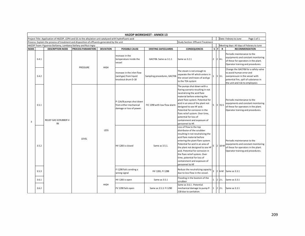
209
NODE DESCRIPTION NODE PROCESS PARAMETERS DEVIATION POSSIBLE CAUSE EXISTING SAFEGUARDS CONSEQUENCES S F R RECOMMENDATION
3.4.1
Increase in the
temperature inside the
vessel
GACF06. Same as 3.1.1 Same as 3.2.1 2 2 4-L
Periodic maintenance to the
equipments and constant monitoring
of these for operators in the plant.
Operator training and procedures.
3.4.2
Increase in the inlet flow
(acid gas) from liquid
knockout drum D-18
Sampling procedures, GACF06
The steam is not enough to
separate the HF which enters in
the vessel and traces of acid go
to the TEA system
1 3 3-L
Change the GACF06 for a safety valve
to avoid human error and
overpressure in the vessel with
potential fire, spill of substance in
the unit and risk to employees
3.5.1
P-11A/B pumps shut down
from either mechanical
damage or loss of power.
FIC 1290 with low flow alarm
The pumps shut down with a
flaring scenario resulting in not
neutralizing the acid flare
material before entering the
plant flare system. Potential for
acid in an area of the plant not
designed to see HF acid.
Potential for corrosion in the
flare relief system. Over time,
potential for loss of
containment and exposure of
personnel to HF.
5 3 15-S
Periodic maintenance to the
equipments and constant monitoring
of these for operators in the plant.
Operator training and procedures.
3.5.2 HV 1265 is closed Same as 3.5.1.
Loss of flow to the top
distributor of the scrubber
resulting in not neutralizing the
acid flare material before
entering the plant flare system.
Potential for acid in an area of
the plant not designed to see HF
acid. Potential for corrosion in
the flare relief system. Over
time, potential for loss of
containment and exposure of
personnel to HF
5 2 10-M
Periodic maintenance to the
equipments and constant monitoring
of these for operators in the plant.
Operator training and procedures.
3.5.3 FI 1290 fails sending a
wrong signal HV 1265, FI 1288
Reduce the neutralizing capacity
due to less flow in the vessel. 3 2 6-M Same as 3.3.1
3.6.1 HV 1265 is open Same as 3.5.1 Flooding in the bootom of the
scrubber1 2 2-L Same as 3.3.1
3.6.2 FV 1290 fails open Same as 3.5.3. FI 1290
Same as 3.6.1 . Potential
mechanical damage to pump P-
11B due to cavitation.
1 2 2-L Same as 3.3.1
RELIEF GAS SCRUBBER V-
06 3
HAZOP WORKSHEET - ANNEX 13 Project Title: Application of HAZOP, LOPA and SIL to the alkylation unit catalyzed with hydrofluoric acid Date: Febrary to June Page 1 of 1
Process: Explain the process of treatment and disposition of effluents generated by the unit Study Section: Effluent Treatment
HAZOP Team: Figueroa Stefanny, Lombana Stefany and Ruiz Ingry Meeting days: All days of Febrary to June
PRESSURE HIGH
LESS
LEVEL
HIGH

210
NODE DESCRIPTION NODE PROCESS PARAMETERS DEVIATION POSSIBLE CAUSE EXISTING SAFEGUARDS CONSEQUENCES S F R RECOMMENDATION
4.1.1 Decrease in the inlet
steam flow rateTI 1300, RO 1301
Increase in the residence time
or setting times. 2 2 4-L
Consider install a flow indicator in the
inlet line to control the flow rate
which enters in the reboiler. Periodic
operator procedures, training and
response.
4.1.2
Decrease in the inlet
stream from P-12A/B
temperature
TI 1300 Same as 4.1.1. 2 2 4-LPeriodic operator procedures,
training and response.
4.2.1 Increase in the inlet steam
flow rate Same as 4.1.1
Potential for higher operating
temperatures in the KOH
Regeneration Tank. Higher
temperatures (typically greater
than 150 degrees F) could result
in caustic embrittlement and
over time replacement of the
vessel.
2 2 4-L Same as 4.1.1
4.2.2 Increase in the inlet lime
flow rate No safeguards
Localized heating at the eductor
S-03 2 2 4-L
Install a shutdown system in the
eductor S-03 which works with a
temperature indicator to control the
temperature inside the tank
4.2.3
Increase in the inlet
stream from P-12A/B
temperature
Same as 4.1.2 Same as 4.2.1 2 2 4-L Same as 4.1.2
4.3.1 LESS Considered but nothing
significant identified
4.4.1 HIGH Considered but nothing
significant identified
4.5.1 Decrease in the inlet
stream flow from P-12A/B
Reflux stream, Stream from
eductor S-03
Increase in the regeneration
time of KOH due to increase in
the batches
1 2 2-L
Install a flow indicator in this line.
Periodic monitoring and maintenance
to pump P-12A/B.
4.5.2
Decrease in the addition of
lime and KOH from eductor
S-03
Stream of KOH from P-12A/B,
Sampling procedures, operator
calculations.
Same as 4.5.1 1 2 2-L
Consider install a flow indicator in the
inlet pipe. Operator procedures and
training. Realize a schedule for
sampling procedures and monitoring
it.
4.5.3 Rupture in the outlet line
to TK-001A/B Line to fire hose connection
Potential risk to the employees
and the equipments. Increase in
the level of TK-001A/B
4 2 8-MSame as 4.5.2. Periodic maintenance
to the pipe.
4.5.4 Free draining lines are
openManual valve GACF04
Increase in the level in the tank
TK-001A/B 1 2 2-L
Operator procedures and periodic
training.
4.5.5 Manual valve GACF04 fails
open No safeguards Same as 4.5.4 1 3 3-L
Constant monitoring to equipments
and periodic operator procedures.
4.5.6 Presence of solids from
the regeneration tank No safeguards
Losing more regenerated
KOH than intended to the
neutralization basin
2 3 6-M
Ensure there is a gap between the
Regeneration Tank drain line and the
Neutralization Basin to see if there is
plugging in the drain line and to
minimize KOH losses
KOH REGENERATION
TANK D-20
LEVEL
4
HAZOP WORKSHEET - ANNEX 13 Project Title: Application of HAZOP, LOPA and SIL to the alkylation unit catalyzed with hydrofluoric acid Date: Febrary to June Page 1 of 1
Process: Explain the process of treatment and disposition of effluents generated by the unit Study Section: Effluent Treatment
HAZOP Team: Figueroa Stefanny, Lombana Stefany and Ruiz Ingry Meeting days: All days of Febrary to June
TEMPERATURE
LESS
HIGH
PRESSURE
LESS
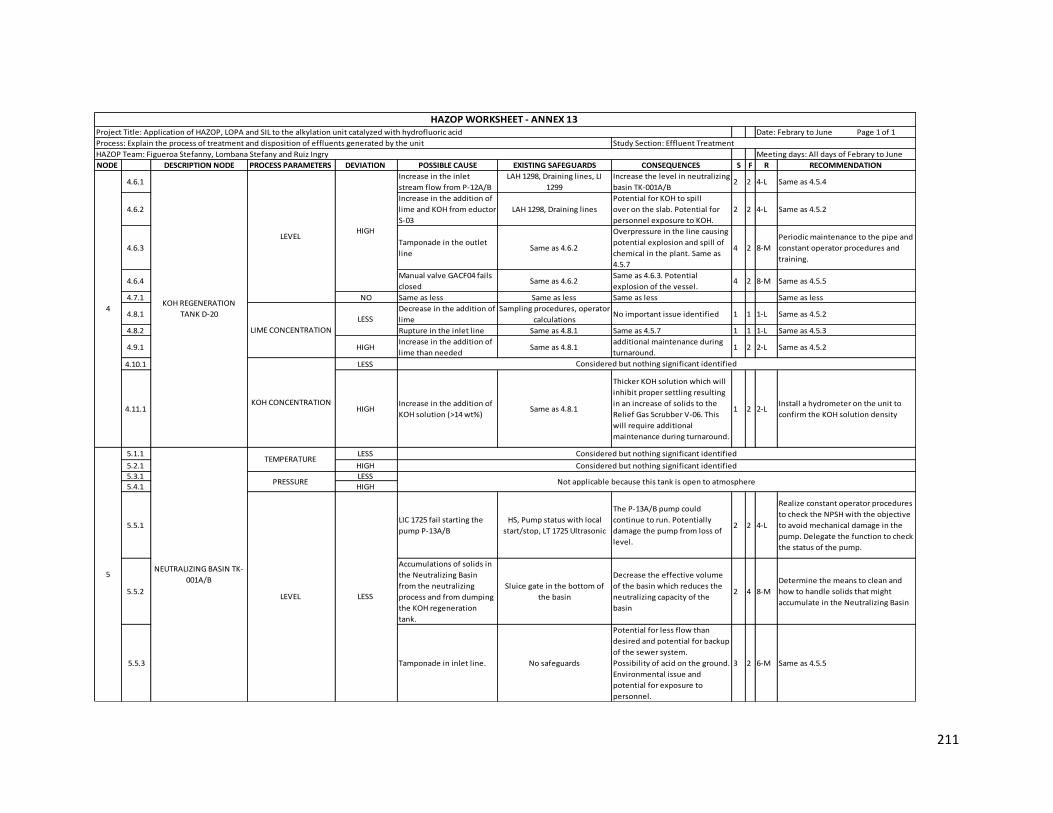
211
NODE DESCRIPTION NODE PROCESS PARAMETERS DEVIATION POSSIBLE CAUSE EXISTING SAFEGUARDS CONSEQUENCES S F R RECOMMENDATION
4.6.1 Increase in the inlet
stream flow from P-12A/B
LAH 1298, Draining lines, LI
1299
Increase the level in neutralizing
basin TK-001A/B2 2 4-L Same as 4.5.4
4.6.2
Increase in the addition of
lime and KOH from eductor
S-03
LAH 1298, Draining lines
Potential for KOH to spill
over on the slab. Potential for
personnel exposure to KOH.
2 2 4-L Same as 4.5.2
4.6.3 Tamponade in the outlet
line Same as 4.6.2
Overpressure in the line causing
potential explosion and spill of
chemical in the plant. Same as
4.5.7
4 2 8-M
Periodic maintenance to the pipe and
constant operator procedures and
training.
4.6.4 Manual valve GACF04 fails
closed Same as 4.6.2
Same as 4.6.3. Potential
explosion of the vessel. 4 2 8-M Same as 4.5.5
4.7.1 NO Same as less Same as less Same as less Same as less
4.8.1 Decrease in the addition of
lime
Sampling procedures, operator
calculationsNo important issue identified 1 1 1-L Same as 4.5.2
4.8.2 Rupture in the inlet line Same as 4.8.1 Same as 4.5.7 1 1 1-L Same as 4.5.3
4.9.1 HIGH Increase in the addition of
lime than neededSame as 4.8.1
additional maintenance during
turnaround.1 2 2-L Same as 4.5.2
4.10.1 LESS
4.11.1 HIGH Increase in the addition of
KOH solution (>14 wt%)Same as 4.8.1
Thicker KOH solution which will
inhibit proper settling resulting
in an increase of solids to the
Relief Gas Scrubber V-06. This
will require additional
maintenance during turnaround.
1 2 2-LInstall a hydrometer on the unit to
confirm the KOH solution density
5.1.1 LESS
5.2.1 HIGH
5.3.1 LESS
5.4.1 HIGH
5.5.1 LIC 1725 fail starting the
pump P-13A/B
HS, Pump status with local
start/stop, LT 1725 Ultrasonic
The P-13A/B pump could
continue to run. Potentially
damage the pump from loss of
level.
2 2 4-L
Realize constant operator procedures
to check the NPSH with the objective
to avoid mechanical damage in the
pump. Delegate the function to check
the status of the pump.
5.5.2
Accumulations of solids in
the Neutralizing Basin
from the neutralizing
process and from dumping
the KOH regeneration
tank.
Sluice gate in the bottom of
the basin
Decrease the effective volume
of the basin which reduces the
neutralizing capacity of the
basin
2 4 8-M
Determine the means to clean and
how to handle solids that might
accumulate in the Neutralizing Basin
5.5.3 Tamponade in inlet line. No safeguards
Potential for less flow than
desired and potential for backup
of the sewer system.
Possibility of acid on the ground.
Environmental issue and
potential for exposure to
personnel.
3 2 6-M Same as 4.5.5
Considered but nothing significant identified
Considered but nothing significant identified
Not applicable because this tank is open to atmosphere
LESS
HIGH
LIME CONCENTRATION
LESS
4
KOH CONCENTRATION
Considered but nothing significant identified
HAZOP WORKSHEET - ANNEX 13 Project Title: Application of HAZOP, LOPA and SIL to the alkylation unit catalyzed with hydrofluoric acid Date: Febrary to June Page 1 of 1
Process: Explain the process of treatment and disposition of effluents generated by the unit Study Section: Effluent Treatment
HAZOP Team: Figueroa Stefanny, Lombana Stefany and Ruiz Ingry Meeting days: All days of Febrary to June
KOH REGENERATION
TANK D-20
TEMPERATURE
PRESSURE
LEVEL
NEUTRALIZING BASIN TK-
001A/B 5
LEVEL

212
NODE DESCRIPTION NODE PROCESS PARAMETERS DEVIATION POSSIBLE CAUSE EXISTING SAFEGUARDS CONSEQUENCES S F R RECOMMENDATION
5.6.1 LIC 1725 fails stopping the
pump P-13A/B Same as 5.5.1
Unable to lower the level in the
pumpout section of the basin.
Unable to transfer from the
neutralizing section of the basin
to the pumpout section and can
reach the maximum liquid level
in the neutralizing basin. Unable
to receive any additional
rundown from the HFS or AWS
system since this is gravity fed.
Possibility of acid on the ground.
Environmental issue and
potential for exposure to
personnel
4 4 16-S
Provide a line to divert the AWS
water from the Neutralizing Basin to
the potentially contaminated
stormwater sump
5.6.2 Incidental maintenance.
LIC 1725 with automatically
starts/stops the pump P-13A/B
and high level alarm. Parallel
basins.
Potential for higher level in the
Neutralizing Basin resulting in
over filling. Unable to receive
any additional rundown from
the HFS or AWS system since
this is gravity fed. Possibility of
acid on the ground.
Environmental issue and
potential for exposure to
personnel.
4 2 8-MOperator procedures and periodic
training.
5.6.3
Flooding in the unit and
the neutralizing basin area
due to heavy rain
No safeguards
Potential for the surface
water from the flooding to enter
the Neutralizing Basin. Potential
to reach the maximum liquid
level in the neutralizing basin.
Unable to receive any additional
rundown from the HFS or AWS
system since this is gravity fed.
Possibility of acid on the ground.
Environmental issue and
potential for exposure to
personnel.
4 4 16-S
Provide a line to divert the AWS
water from the Neutralizing Basin to
the potentially contaminated
stormwater sump
5.6.4 Pumps P-13A/B shut down Same as 5.5.1 Same as 5.6.1 4 4 16-S Same as 5.6.3
LEVEL NEUTRALIZING BASIN TK-
001A/B 5
HAZOP WORKSHEET - ANNEX 13 Project Title: Application of HAZOP, LOPA and SIL to the alkylation unit catalyzed with hydrofluoric acid Date: Febrary to June Page 1 of 1
Process: Explain the process of treatment and disposition of effluents generated by the unit Study Section: Effluent Treatment
HAZOP Team: Figueroa Stefanny, Lombana Stefany and Ruiz Ingry Meeting days: All days of Febrary to June
HIGH

213
Annex 14 Application of LOPA and SIL methodology to Selective Hydrogenation section
NODE DESCRIPTIO
N NODE
PROCESS
PARAMETERS DEVIATION
POSSIBLE
CAUSEEXISTING SAFEGUARDS CONSEQUENCES F
INITIATING
EVENT
FREQUENCY
RECOMMENDATION PROCESS
DESING PROCEDURES
RELIEF
DEVICE
EMERGENCY
RESPONSE
OVERALL
CONSEQUENCE
FREQUENCY
SILs for
SIFsSIL RECOMMENDATION
1FEED SURGE
DRUM D-201 PRESSURE LESS
PIC 4007 fails
opened PV
4007A due to
malfunctions
* Pressure of Nitrogen is 95
psig and pressure of the drum
is 180 psig using for decreasse
the pressure inside the tank
*Relief valve (Fuel gas purges
to the refinery flare system)
*Bypass system (LWCS01)
* Manual valves before and
after PV 4007A (GWCS01)
*Operator procedures,
training and response
Higher flow rate of
Nitrogen to the flare to the
plant flare header.
Potential impact to the
flare (loss of the flare).
Releasing to the
atmosphere unburnt
Hydrocarbons, potential
ground fires.
Environmental issue and
potential for personnel
injury.
3 1,00E-03
Constant check if the
Nitrogen purge flow
worked in the permits
limits
1,00E-05 1,00E-01 1,00E-02 1,00E-02 1,00E-13
The hazard from this
equipment generates
with this deviation
was mitigated with
the safeguards that
the process has
PRESSURE HIGH
The valve PSV
4037 or PSV
4047 fails
open due to
malfunctions
*Manual valve GBCF03
*Operator procedures,
training and response
Release of hydrogen to the
atmosphere causing air
pollution. 3 1,00E-03
Periodic monitoring of
the safety valves PSV
4037 or PSV 4047 to
prevent desviation
and possibles risks
1,00E-05 1,00E-01 1,00E-02 1,00E-02 1,00E-13
The hazard from this
equipment generates
with this deviation
was mitigated with
the safeguards that
the process has
LEVEL HIGH
Due to
malfunctions
the PCV 4149
fails opened
increased the
nitrogen flow
* Relief valve (Fuel gas
purges to the refinery flare
system)
*Operator procedures,
training and response
More nitrogen to the flare
header. Potencial impact to
the flare (loss of the flare).
Possible risk to employees.
Enviromental contaminant
3 1,00E-03
Constant monitoring
and maintenance of
the valves and
constant check of the
correct procedures
1,00E-01 1,00E-02 1,00E-02 1,00E-08
The hazard from this
equipment generates
with this deviation
was mitigated with
the safeguards that
the process has
5STRIPPER T-
201TEMPERATURE HIGH
Due to
malfunctions
the PV 4051
fails closed
interrupting
the olefins
flow
*Bypass System (LBCF01)
*Manual valves GBCF01
before and after at pressure
valve
*Operator procedures,
training and response
The stripper would need
less heat from reboiler E-
203. Presence of
hydrocarbon vaporised in
the top of the
issostroppier. Hydrogen
contamination. Decrease in
the propane concentration.
Economic losses.
Overpressure in the line
pipe. Possible rupture of
the pipe line due the
overpressure causing a
posible fire explosion
generating risk for the
employees, enviroment
and equipment.
3 1,00E-03
Constant monitoring
of the operated
system.
Decrease the
recirculation flow
from reboiler E-203.
Increase in the flow of
the top.
1,00E-05 1,00E-02 1,00E-02 1,00E-12
The hazard from this
equipment generates
with this deviation
was mitigated with
the safeguards that
the process has
HAZOP WITH LOPA/SIL WORKSHEET - ANNEX 14
Project Title: Application of HAZOP, LOPA and SIL to the alkylation unit catalyzed with hydrofluoric acid Date: Febrary to June Page 1 of 1 1,00E-08
Process: The objective is the removal of diolefins and light fractions of the olefins stream Study Section: Selective Hydrogenation
HAZOP Team: Figueroa Stefanny, Lombana Stefany and Ruiz Ingry INDEPENDENT PROTECTION LAYERS
4REACTORS
R-201/202
ACCEPTABLE RISK CRITERIA
Meeting days: All days of Febrary to June

214
Annex 15 Application of LOPA and SIL methodology to Charge and Drying section
NODE DESCRIPTION
NODE
PROCESS
PARAMETER
S
DEVIATION POSSIBLE
CAUSE
EXISTING
SAFEGUARDSCONSEQUENCES F
INITIATING
EVENT
FREQUENCY
RECOMMENDATION PROCESS
DESING BPCS ALARM PROCEDURES SIS
EMERGENCY
RESPONSE
OVERALL
CONSEQUENC
E FREQUENCY
SILs
for
SIFs
SIL RECOMMENDATION
1.5.6
Rupture or
leak in the
principle
inlet line to
D-02
* Manuals valves
CBCF01/
LWCS03/ LBCF06
to close the inlet
flow for each
streams IPL 1
* XV 2453 IPL2
*FV1006 IPL2
*Operator
procedures,
training and
response
*Emergency
response IPL3
Potential fire and
explosion.
Hydrocarbon spill to
atmosphere causing
air pollution. Risk to
the employees and
the equipments.
Economic losses.
Decrease in the
NPSH causing
cavitation in the
pump P-01A/B.
Decrease in the
pressure tank
3 1,00E-03
Install a Flow
Indicator in the inlet
line of surge drum
and flow indicator
with lower and higher
Alarm in the drum.
Constantly check of
the pipe and realize
maintenance to the
pipes and vessels and
training to the
operator if this cause
occurs.
1,00E-05 1,00E-02 1,00E-01 1,00E-02 1,00E-02 1,00E-15
The hazard from this
equipment generates
with this deviation
was mitigated with
the safeguards that
the process has
1.5.8
Rupture in
the outlet
lines of the
drum D-02
*LI 1005 with low
level and low-
low alarm IPL1
*Manual valve
GWCS03 IPL2
*XV 1516
*Operator
Same as 1.5.6 3 1,00E-03
Install a Flow
Indicator in the outlet
line of the surge
drum. Realize
operator procedures
and training
1,00E-05 1,00E-02 1,00E-01 1,00E-01 1,00E-02 1,00E-02 1,00E-16
The hazard from this
equipment generates
with this deviation
was mitigated with
the safeguards that
the process has
1.6.5 HIGH
LV 1004
fails closed
for
example
bad
transmitter
or loss of
instrument
air
*Bypass system
around valve LV
1004 with
manual valve
LWCS03
*LI 1005 with low
level and low-
low alarm and
high level and
high - high
alarm
Drag the acid to the
Isostripper section
Overpressure in the
tank causing
possible explosion.
Drag of hydrocarbon
to the TEA system.
Drag of water to the
dryers D-03A/B.
Increase in the
corrosion of
equipments. Loss of
acid due to the
increase of water.
Potential for water
buildup and water
carryover to the
dryer leading to
potential corrosion
in downstream
system. Overtime,
possible leaks of
acid in downstream
equipments with
possible exposure
to employees.
Economic losses
3 1,00E-03
Periodic maintenance
to the bypass line,
pipes and surge drum.
Consider adding an
HF/Water acid
analyzer on the E-28/E-
28A reactor acid
circulation loop
1,00E-05 1,00E-01 1,00E-01 1,00E-02 1,00E-12
The hazard from this
equipment generates
with this deviation
was mitigated with
the safeguards that
the process has
Process: The objective is to remove humidity of the charge currents the unit Study Section: Charge and Drying
ACCEPTABLE RISK CRITERIA
HAZOP WITH LOPA/SIL WORKSHEET - ANNEX 15
Project Title: Application of HAZOP, LOPA and SIL to the alkylation unit catalyzed with hydrofluoric acid Date: Febrary to June Page 1 of 1 1,00E-08
HAZOP Team: Figueroa Stefanny, Lombana Stefany and Ruiz Ingry INDEPENDENT PROTECTION LAYERS
Surge Drum D-
02LEVEL
LESS
Meeting days: All days of Febrary to June
1

215
Annex 16 Application of LOPA and SIL methodology to Reaction section
NODE DESCRIPTION
NODE
PROCESS
PARAMETER
S
DEVIATION POSSIBLE
CAUSE
EXISTING
SAFEGUARD
S
CONSEQUENCES F
INITIATING
EVENT
FREQUENCY
RECOMMENDATION PROCESS
DESING PROCEDURES
RELIEF
DEVICE
EMERGENCY
RESPONSE
OVERALL
CONSEQUENCE
FREQUENCY
SILs
for
SIFs
SIL RECOMMENDATION
NEW
OVERAL
L
1REACTOR
E28/28ATEMPERATURE HIGH
The cooling
flow is
interrupted
due to the
FBCF01 fails
closed for
human
error
* TI 1548
*PI1546
*PSV
1048/1915
*Operator
procedure
training and
response
Runaway
reaction with
subsequent
increase in the
vessel pressure
possibly leading
to a rupture or
explosion of the
vessel
3 1,00E-03
Installation of a
cooling water flow
indicator and low
flow alarm to provide
an immediate
indication of cooling
loss. Periodic
inspections and
maintenance of the
cooling system , PSV
and Manual valve to
insure its integrity.
Change the manual
valve to an automatic
valve. Installation of
a high temperature
alarm to alert the
operator in the event
of cooling function
loss. Evaluation of
the cooling water
source to consider
any possible
interruption and
contamination of the
supply.
1,00E-01 1,00E-01 1,00E-02 1,00E-02 1,00E-09
Install a Flow
Indicator Control
with Low Flow Alarm
which is located in
the inlet pipe of the
cooling water to
maintain the process
flow in the reactors*
1,00E-11
HAZOP WITH LOPA/SIL WORKSHEET - ANNEX 16
Date: Febrary to June Page 1 of 1
INDEPENDENT PROTECTION LAYERS
Project Title: Application of HAZOP, LOPA and SIL to the alkylation unit catalyzed with
hydrofluoric acid
HAZOP Team: Figueroa Stefanny, Lombana Stefany and Ruiz Ingry Meeting days: All days of Febrary to June
1,00E-08
Study Section: ReactionProcess: Explains the reaction between the olefins and isobutane in the presence of
hydrofluoric acid to obtain the alkylate
ACCEPTABLE RISK CRITERIA
*We considerate install this recommendation to mitigate completely this scenery
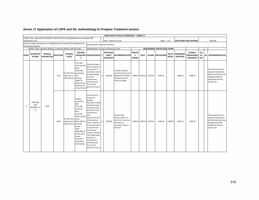
216
Annex 17 Application of LOPA and SIL methodology to Propane Treatment section
NODE DESCRIPTIO
N NODE
PROCESS
PARAMETERS DEVIATION
POSSIBLE
CAUSE
EXISTING
SAFEGUARD
S
CONSEQUENCES F
INITIATING
EVENT
FREQUENCY
RECOMMENDATION
PROCES
S
DESING
BPCS ALARM PROCEDURESRELIEF
DEVICE
EMERGENCY
RESPONSE
OVERALL
CONSEQUENC
E FREQUENCY
SILs
for
SIFs
SIL RECOMMENDATION
LESS
PV-2417 fails
open due to
malfunctions
*FIC-2415
with low flow
alarm
*Operator
procedures
and
training
*GBCF 16
Manual valve
located after
of the PV 2417
Potential vapors
and cavitation of
the pump P-17
resulting in seals
leaking leading
to loss of
containment
with potential
for fire and
personnel injury
3 1,00E-03
Consider adding a
Low Flow Alarm to FI-
2423A and FI-2423B.
(Propane product
flow to storage)
1,00E-05 1,00E-01 1,00E-01 1,00E-01 1,00E-02 1,00E-13
The hazard from this
equipment generates
with this deviation was
mitigated with the
safeguards that the
process has
HIGH
PV-2417 fails
closed due to
malfunctions
*Bypass
around PV-
2417
*FIC-2415
minimum
flow
controller
with low flow
alarm
*PSV-2414 on
the KOH
treater
*PSV-
2407/2408 on
the Alumina
treater
*Operator
procedures
and training
Loss of flow of
product to
storage.
Potential to dead
head the pumps
resulting in seal
leaks and loss of
containment
with
potential for fire
and personnel
injury. Potential
for overpressure
in the KOH and
the Alumina
treaters.Potentia
l for flange leaks
and loss of
containment
with potential
for fire and
personnel injury
3 1,00E-03
Install a High
Pressure Alarm in
the D-15 in case that
the pressure
increases inside of
the tank
1,00E-05 1,00E-01 1,00E-01 1,00E-02 1,00E-02 1,00E-02 1,00E-16
The hazard from this
equipment generates
with this deviation was
mitigated with the
safeguards that the
process has
INDEPENDENT PROTECTION LAYERS
3
PROPANE
KOH
TREATERS D-
15
LEVEL
HAZOP Team: Figueroa Stefanny, Lombana Stefany and Ruiz Ingry Meeting days: All days of Febrary to June
HAZOP WITH LOPA/SIL WORKSHEET - ANNEX 17 Project Title: Application of HAZOP, LOPA and SIL to the alkylation unit catalyzed with
hydrofluoric acid Date: Febrary to June Page 1 of 1 1,00E-08
Process: Explain the process of conditioning and removal of contaminant of
the product propane Study Section: Propane treatment
ACCEPTABLE RISK CRITERIA
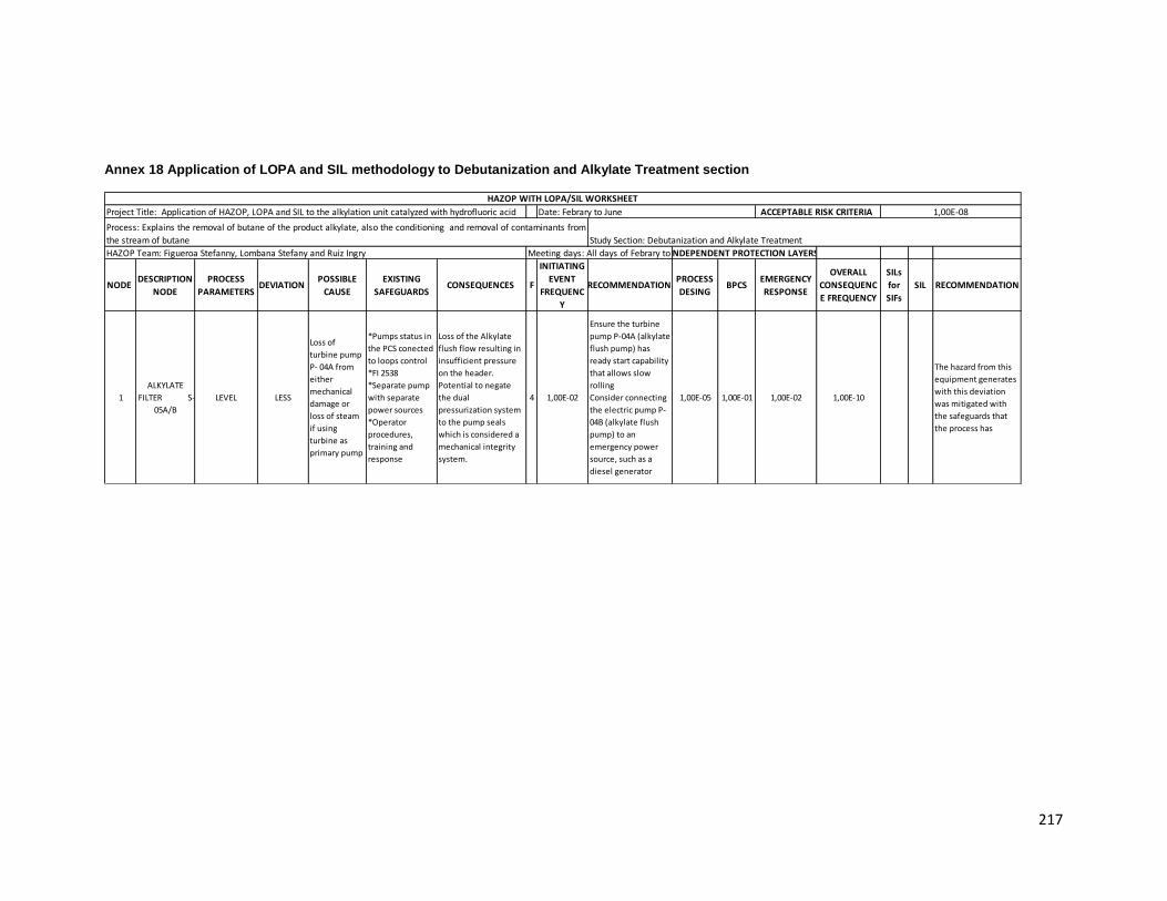
217
Annex 18 Application of LOPA and SIL methodology to Debutanization and Alkylate Treatment section
NODE DESCRIPTION
NODE
PROCESS
PARAMETERS DEVIATION
POSSIBLE
CAUSE
EXISTING
SAFEGUARDSCONSEQUENCES F
INITIATING
EVENT
FREQUENC
Y
RECOMMENDATION PROCESS
DESING BPCS
EMERGENCY
RESPONSE
OVERALL
CONSEQUENC
E FREQUENCY
SILs
for
SIFs
SIL RECOMMENDATION
1
ALKYLATE
FILTER S-
05A/B
LEVEL LESS
Loss of
turbine pump
P- 04A from
either
mechanical
damage or
loss of steam
if using
turbine as
primary pump
*Pumps status in
the PCS conected
to loops control
*FI 2538
*Separate pump
with separate
power sources
*Operator
procedures,
training and
response
Loss of the Alkylate
flush flow resulting in
insufficient pressure
on the header.
Potential to negate
the dual
pressurization system
to the pump seals
which is considered a
mechanical integrity
system.
4 1,00E-02
Ensure the turbine
pump P-04A (alkylate
flush pump) has
ready start capability
that allows slow
rolling
Consider connecting
the electric pump P-
04B (alkylate flush
pump) to an
emergency power
source, such as a
diesel generator
1,00E-05 1,00E-01 1,00E-02 1,00E-10
The hazard from this
equipment generates
with this deviation
was mitigated with
the safeguards that
the process has
HAZOP Team: Figueroa Stefanny, Lombana Stefany and Ruiz Ingry INDEPENDENT PROTECTION LAYERS
ACCEPTABLE RISK CRITERIA
HAZOP WITH LOPA/SIL WORKSHEET
Project Title: Application of HAZOP, LOPA and SIL to the alkylation unit catalyzed with hydrofluoric acid Date: Febrary to June Page 1 of 1 1,00E-08
Process: Explains the removal of butane of the product alkylate, also the conditioning and removal of contaminants from
the stream of butane
Meeting days: All days of Febrary to June
Study Section: Debutanization and Alkylate Treatment

218
Annex 19 Application of LOPA and SIL methodology to N-Butane Treatment section
DESCRIPTION
NODE
PROCESS
PARAMETER
S
DEVIATION POSSIBLE
CAUSE
EXISTING
SAFEGUARDSCONSEQUENCES F
INITIATING
EVENT
FREQUENCY
RECOMMENDATION BPCSRELIEF
DEVICE
EMERGENCY
RESPONSE
OVERALL
CONSEQUENC
E FREQUENCY
SILs for
SIFsSIL RECOMMENDATION
NEW
OVERALL
TREATERS
WITH ALUMINA
D-09A-D
PRESSURE HIGH
Manual valve
GBCF13 it will
closed due to
human factors
*Operator
procedures,
training and
response
Decrease in the efficiency
of removal of fluoride in
the alumina treater
Overpressure in the
pipeline causing possible
rupture
Possible fire explosion due
to a possible rupture
Air pollution
Risk to employees
Economic losses
3 1,00E-03
Install a control valve
with a loop that worked
together to avoid
possibles damages
Ensure good
communication between
employees
1,00E-02 1,00E-02 1,00E-07 1,00E-01 SIL 2
Is necessary install a
safeguard SIL 1 with a
loop control BPCS
and SIL 4 with a
bypass system
between control
valve
1,00E-13
N-BUTANE
COALESCERS
D10/10A
PRESSURE HIGH
Tamponad in
the outside
pipeline of the
N-Butane exit
*PIC 1219/1984
worked with a
control valve
*Operator
procedures,
training and
response
Overpressure in the
outside pipeline causing
possible rupture
Possible fire explosion due
to a rupture of the pipeline
Air pollution
Risk to employees
Economic losses
3 1,00E-03
Install a flow indicator
system in the inlet
stream for control the
flow that enter in the
coalescer
Constant maintenance to
the pipeline to ensure
the proper functioning
1,00E-01 1,00E-02 1,00E-02 1,00E-08 1,00E+00 SIL 1
Is required a SIL 4
with a bypass system
that worked between
pressure indicator
control
1,00E-13
HAZOP Team: Figueroa Stefanny, Lombana Stefany and Ruiz Ingry
INDEPENDENT PROTECTION
LAYERS
ACCEPTABLE RISK CRITERIA
HAZOP WITH LOPA/SIL WORKSHEET - ANNEX 19
Project Title: Application of HAZOP, LOPA and SIL to the alkylation unit catalyzed with hydrofluoric acid Date: Febrary to June Page 1 of 1 1,00E-08
Meeting days: All days of Febrary to June
Study Section: N-Butane TreatmentProcess: Explain the process of conditioning and removal of contaminant of the product N-Butane
SAFEGUARDS PROCESS DESING BPCSOVERALL CONSEQUENCE
FREQUENCY
*Loop control that
worked with a flow
valve
*Bypass system to
avoid problems
1,00E-05 1,00E-01 1,00E-13
*Bypass System
between Pressure
indicator control
1,00E-05 1,00E-13

219
Annex 20 Application of LOPA and SIL methodology to Cooling Water Tower -TAE- section
NODE DESCRIPTION
NODE
PROCESS
PARAMETERS DEVIATION
POSSIBLE
CAUSE
EXISTING
SAFEGUARDSCONSEQUENCES F
INITIATING
EVENT
FREQUENCY
RECOMMENDATION BPCS PROCEDURESEMERGENCY
RESPONSE
OVERALL
CONSEQUENC
E FREQUENCY
SILs
for
SIFs
SILRECOMMENDATIO
N
1 1.7.2 COOLING TOWER
CT-401
COMPOSITION
(WATER PURITY)LESS
Leak of
hydrocarbon
*AI 2003
*Interlock UC 31
*AIC 2026
*AI 2027
*Additive to
maintain
equipment
integrity
*Sampling
procedures
*Operator
procedures,
training and
response
Presence of
hydrocarbon in the
cooling water
system. Possible
fire and
employees injury.
3 1,00E-03
Install a measuring
element level low
(LEL) in the cooling
system
1,00E-02 1,00E-01 1,00E-02 1,00E-08
The hazard from this
equipment generates
with this deviation
was mitigated with
the safeguards that
the process has
HAZOP Team: Figueroa Stefanny, Lombana Stefany and Ruiz Ingry INDEPENDENT PROTECTION LAYERS
ACCEPTABLE RISK CRITERIA
HAZOP WITH LOPA/SIL WORKSHEET - ANNEX 20
Project Title: Application of HAZOP, LOPA and SIL to the alkylation unit catalyzed with hydrofluoric acid Date: Febrary to June Page 1 of 1 1,00E-08
Process: Discusses the cooling system of the cooling water of unit Study Section: Cooling Water Tower TAE
Meeting days: All days of Febrary to June

220
Annex 21 Application of LOPA and SIL methodology to HF Regeneration section
NODE DESCRIPTION
NODE
PROCESS
PARAMETER
S
DEVIATION POSSIBLE
CAUSE
EXISTING
SAFEGUARDSCONSEQUENCES F
INITIATING
EVENT
FREQUENCY
RECOMMENDATION PROCESS
DESING BPCS PROCEDURES
OVERALL
CONSEQUENCE
FREQUENCY
SILs for
SIFsSIL RECOMMENDATION
1.2.2FV 1171 fails
closed
*Intermittent
flow from ALKAD
section IPL 1
*Lab sampling
IPL 2
*hand wheel on
FV 1171 IPL 3
*TIC 1168 which
will add reflux to
maintain the
overhead
temperature of
the regenerator
IPL 4 *Operator
procedures,
training and
response
Decrease in the HF
inlet flow rate
decreasing the
remotion of soluble
pollutants in the
acid. For a short
period of time,
there are no
significant
consequences. For a
longer period of
time, potential for
hotter overhead
temperature in the
regenerator. Loss of
acid purity resulting
in acid runaway.
Potential for
corrosion, leaks, and
personnel injury.
Losses in the acid
purity. Increase in
the production of
organics fluorides
and polimerization
in the reaction
section.
3 1,00E-03
Install a FIC in the
inlet line of the
regenerator V-03
(after valve FV 1171)
which works with a
flow valve in the
intermittent flow line
to increase the flow
rate in case of this
valve or FIC 1171
which regulate the
valve fails and
mantein the
operational range (626
BDP). Verify sampling
schedule and
frequency for
isobutane and Olefin
Feed. Consider adding
an HF / Water acid
analyzer on the E-
28/E28A reactor acid
circulation loop.
Create a calculation in
PCS for the V-03 acid
regenerator Isobutane
and acid ratio.
1,00E-02 1,00E-02 1,00E-02 1,00E-09 1,00E+01
The hazard from this
equipment generates
with this deviation
was mitigated with
the safeguards that
the process has
1.2.4
TV 1168
malfunctions
closed
*FI-1170 flow
indication.
*TI-1625
temperature
indication IPL 1
*Hand wheel on
TV-1168.
*Operator
procedures,
training and
response
Decrease in the
isobutane from the
depropanizer and HF
stripper section.
Higher corrosion in
the column V-03.
Drag of pollutants
to isostripper
section.Loss of
Regenerator reflux
resulting in higher
overhead
temperatures.
Potential for higher
corrosion in the acid
regenerator. Over a
longer period of
time, potential for
increased impurities
in the acid. Over
time, potential for
acid runaway.
3 1,00E-03
Install a higher
temperature alarm in
the line. Constant
monitoring to the
temperature in the
control room. Periodic
maintenance to the
controllers (adjust the
set point) and valves
to avoid this kind of
problems in the plant.
1,00E-04 1,00E-01 1,00E-08 1,00E+00
The hazard from this
equipment generates
with this deviation
was mitigated with
the safeguards that
the process has
HAZOP WITH LOPA/SIL WORKSHEET - ANNEX 21
Project Title: Application of HAZOP, LOPA and SIL to the alkylation unit catalyzed with hydrofluoric acid Date: Febrary to June Page 1 of 1 1,00E-08
Process: Explain the process of removal of polymer and humidity of the hydrofluoric acidStudy Section: HF Regeneration
HAZOP Team: Figueroa Stefanny, Lombana Stefany and Ruiz Ingry
INDEPENDENT PROTECTION
LAYERS
TEMPERATURE HIGH
Meeting days: All days of Febrary to
June
1
Acid
Regenerator V-
03, IsoButane
Superheater
E-17, Iso
Butane
Superheater
Condensate
Pot D-28
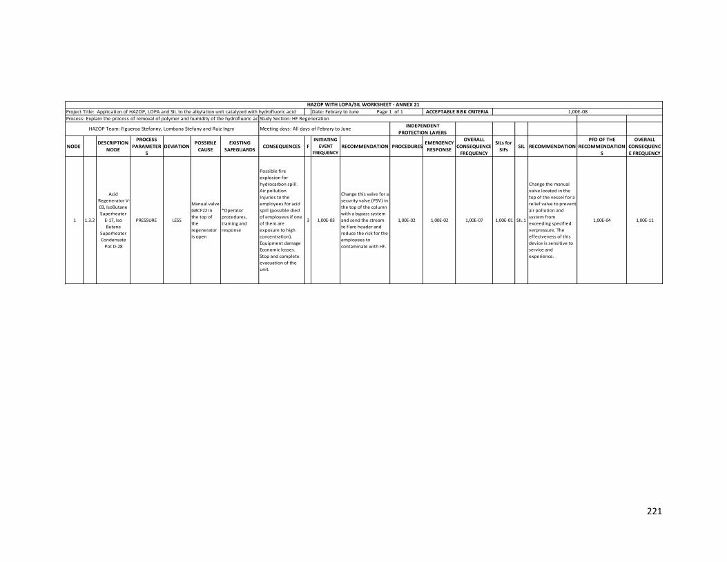
221
NODE DESCRIPTION
NODE
PROCESS
PARAMETER
S
DEVIATION POSSIBLE
CAUSE
EXISTING
SAFEGUARDSCONSEQUENCES F
INITIATING
EVENT
FREQUENCY
RECOMMENDATION PROCEDURESEMERGENCY
RESPONSE
OVERALL
CONSEQUENCE
FREQUENCY
SILs for
SIFsSIL RECOMMENDATION
PFD OF THE
RECOMMENDATION
S
OVERALL
CONSEQUENC
E FREQUENCY
1 1.3.2
Acid
Regenerator V-
03, IsoButane
Superheater
E-17, Iso
Butane
Superheater
Condensate
Pot D-28
PRESSURE LESS
Manual valve
GBCF22 in
the top of
the
regenerator
is open
*Operator
procedures,
training and
response
Possible fire
explosion for
hydrocarbon spill.
Air pollution
Injuries to the
employees for acid
spill (possible died
of employees if one
of them are
exposure to high
concentration).
Equipment damage
Economic losses.
Stop and complete
evacuation of the
unit.
3 1,00E-03
Change this valve for a
security valve (PSV) in
the top of the column
with a bypass system
and send the stream
to flare header and
reduce the risk for the
employees to
contaminate with HF.
1,00E-02 1,00E-02 1,00E-07 1,00E-01 SIL 1
Change the manual
valve located in the
top of the vessel for a
relief valve to prevent
air pollution and
system from
exceeding specified
verpressure. The
effectveness of this
device is sensitive to
service and
experience.
1,00E-04 1,00E-11
Project Title: Application of HAZOP, LOPA and SIL to the alkylation unit catalyzed with hydrofluoric acid Date: Febrary to June Page 1 of 1
Process: Explain the process of removal of polymer and humidity of the hydrofluoric acidStudy Section: HF Regeneration
ACCEPTABLE RISK CRITERIA
HAZOP WITH LOPA/SIL WORKSHEET - ANNEX 21
1,00E-08
INDEPENDENT
PROTECTION LAYERSHAZOP Team: Figueroa Stefanny, Lombana Stefany and Ruiz Ingry Meeting days: All days of Febrary to June
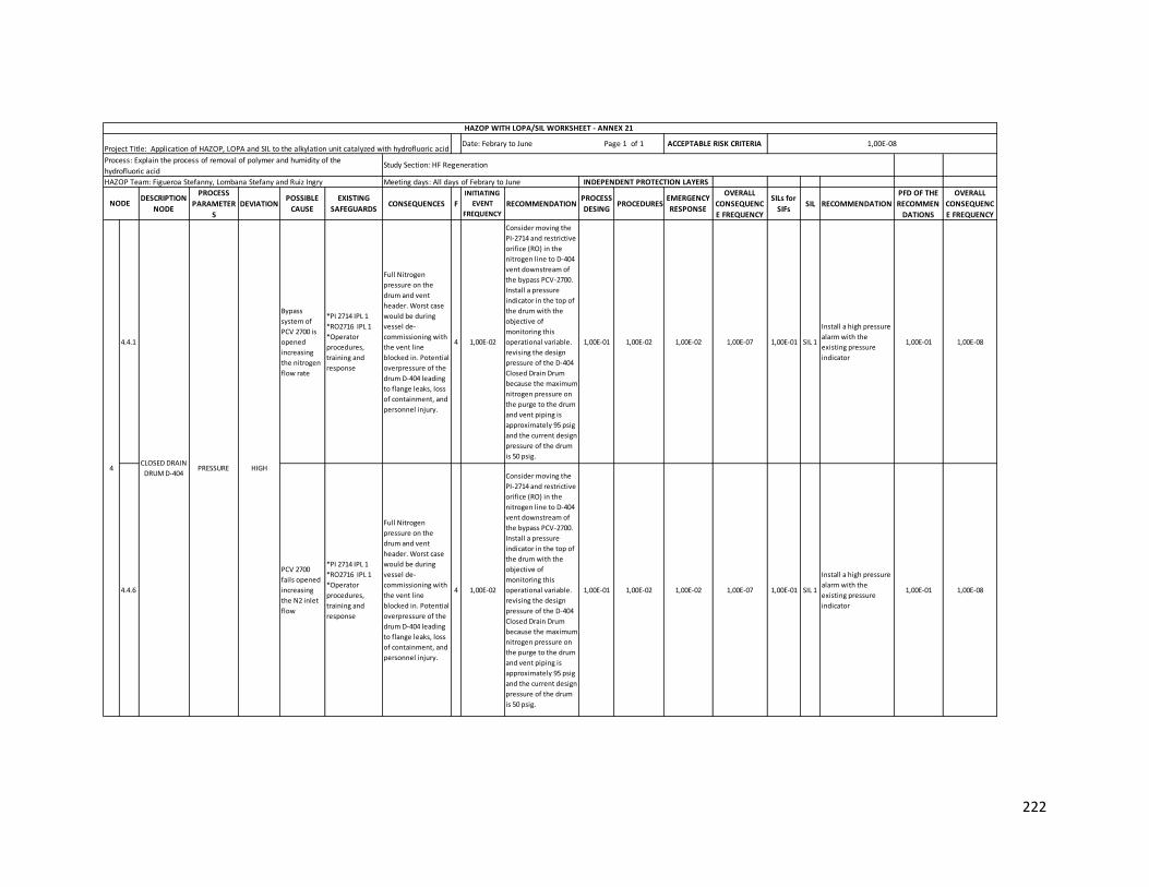
222
DESCRIPTION
NODE
PROCESS
PARAMETER
S
DEVIATION POSSIBLE
CAUSE
EXISTING
SAFEGUARDSCONSEQUENCES F
INITIATING
EVENT
FREQUENCY
RECOMMENDATION PROCESS
DESING PROCEDURES
EMERGENCY
RESPONSE
OVERALL
CONSEQUENC
E FREQUENCY
SILs for
SIFsSIL RECOMMENDATION
PFD OF THE
RECOMMEN
DATIONS
OVERALL
CONSEQUENC
E FREQUENCY
4.4.1
Bypass
system of
PCV 2700 is
opened
increasing
the nitrogen
flow rate
*PI 2714 IPL 1
*RO2716 IPL 1
*Operator
procedures,
training and
response
Full Nitrogen
pressure on the
drum and vent
header. Worst case
would be during
vessel de-
commissioning with
the vent line
blocked in. Potential
overpressure of the
drum D-404 leading
to flange leaks, loss
of containment, and
personnel injury.
4 1,00E-02
Consider moving the
PI-2714 and restrictive
orifice (RO) in the
nitrogen line to D-404
vent downstream of
the bypass PCV-2700.
Install a pressure
indicator in the top of
the drum with the
objective of
monitoring this
operational variable.
revising the design
pressure of the D-404
Closed Drain Drum
because the maximum
nitrogen pressure on
the purge to the drum
and vent piping is
approximately 95 psig
and the current design
pressure of the drum
is 50 psig.
1,00E-01 1,00E-02 1,00E-02 1,00E-07 1,00E-01 SIL 1
Install a high pressure
alarm with the
existing pressure
indicator
1,00E-01 1,00E-08
4.4.6
PCV 2700
fails opened
increasing
the N2 inlet
flow
*PI 2714 IPL 1
*RO2716 IPL 1
*Operator
procedures,
training and
response
Full Nitrogen
pressure on the
drum and vent
header. Worst case
would be during
vessel de-
commissioning with
the vent line
blocked in. Potential
overpressure of the
drum D-404 leading
to flange leaks, loss
of containment, and
personnel injury.
4 1,00E-02
Consider moving the
PI-2714 and restrictive
orifice (RO) in the
nitrogen line to D-404
vent downstream of
the bypass PCV-2700.
Install a pressure
indicator in the top of
the drum with the
objective of
monitoring this
operational variable.
revising the design
pressure of the D-404
Closed Drain Drum
because the maximum
nitrogen pressure on
the purge to the drum
and vent piping is
approximately 95 psig
and the current design
pressure of the drum
is 50 psig.
1,00E-01 1,00E-02 1,00E-02 1,00E-07 1,00E-01 SIL 1
Install a high pressure
alarm with the
existing pressure
indicator
1,00E-01 1,00E-08
NODE
Project Title: Application of HAZOP, LOPA and SIL to the alkylation unit catalyzed with hydrofluoric acidDate: Febrary to June Page 1 of 1
Process: Explain the process of removal of polymer and humidity of the
hydrofluoric acidStudy Section: HF Regeneration
ACCEPTABLE RISK CRITERIA
HAZOP WITH LOPA/SIL WORKSHEET - ANNEX 21
1,00E-08
4CLOSED DRAIN
DRUM D-404 PRESSURE HIGH
INDEPENDENT PROTECTION LAYERSHAZOP Team: Figueroa Stefanny, Lombana Stefany and Ruiz Ingry Meeting days: All days of Febrary to June

223
Annex 22 Application of LOPA and SIL methodology to Effluent Treatment section
DESCRIPTION
NODE
PROCESS
PARAMETERS DEVIATION
POSSIBLE
CAUSE
EXISTING
SAFEGUARDSCONSEQUENCES F
INITIATING
EVENT
FREQUENCY
RECOMMENDATION BPCS ALARM PROCEDURES
OVERALL
CONSEQUENCE
FREQUENCY
SILs for
SIFsSIL RECOMMENDATION
PFD OF THE
RECOMME
NDATIONS
OVERALL
CONSEQUENCE
FREQUENCY
3.3.1 PRESSURE LESS
Manual
valve
GACF06 is
open
*Operator
procedures,
training and
response
Risk to the
employees and
equipments. Air
pollution.
Economic losses.
3 1,00E-03
Periodic maintenance
to the equipments
and constant
monitoring of these
for operators in the
plant. Operator
training and
procedures. Change
the GACF06 for a
safety valve to avoid
human error
1,00E-02 1,00E-05 1,00E-03 SIL 2
Change the manual
valve located in the
top of the vessel for a
relief valve to prevent
air pollution and
system from
exceeding specified
overpressure. The
effectiveness of this
device is sensitive to
service and
experience.
1,00E-04 1,00E-09
3.5.1 LEVEL LESS
P-11A/B
pumps shut
down from
either
mechanical
damage or
loss of
power.
*FIC 1290 with
low flow alarm
IPL 1
*Operator
procedures,
training and
response
The pumps shut
down with a
flaring scenario
resulting in not
neutralizing the
acid flare material
before entering
the plant flare
system. Potential
for acid in an area
of the plant not
designed to see HF
acid. Potential for
corrosion in the
flare relief system.
Over time,
potential for loss
of containment
and exposure of
personnel to HF.
3 1,00E-03
Periodic maintenance
to the equipments
and constant
monitoring of these
for operators in the
plant. Operator
training and
procedures.
1,00E-01 1,00E-01 1,00E-01 1,00E-06 1,00E-02 SIL 1
Due to is a damage in
the pump recommend
to install a active IPL
as Human action with
no more than 20 min
of response time to
simple well-
documented action
with clear and reliable
indications that the
action is required
1,00E-02 1,00E-08
NODE
Project Title: Application of HAZOP, LOPA and SIL to the alkylation unit catalyzed with hydrofluoric acid
Process: Explain the process of treatment and disposition of effluents generated by the unit
HAZOP WITH LOPA/SIL WORKSHEET - ANNEX 22
ACCEPTABLE RISK CRITERIADate: Febrary to June Page 1 of 1
Meeting days: All days of Febrary to June HAZOP Team: Figueroa Stefanny, Lombana Stefany and Ruiz Ingry
1,00E-08
Study Section: Effluent Treatment
INDEPENDENT PROTECTION LAYERS
3RELIEF GAS
SCRUBBER V-06

224
DESCRIPTION
NODE
PROCESS
PARAMETERS DEVIATION
POSSIBLE
CAUSE
EXISTING
SAFEGUARDSCONSEQUENCES F
INITIATING
EVENT
FREQUENCY
RECOMMENDATION PROCESS
DESING PROCEDURES
OVERALL
CONSEQUENCE
FREQUENCY
SILs for
SIFsSIL RECOMMENDATION
PFD OF THE
RECOMME
NDATIONS
OVERALL
CONSEQUENCE
FREQUENCY
5.6.1
LIC 1725
fails
stopping
the pump
P-13A/B
*HS
*Pump status
with local
start/stop IPL 1
*LT 1725
Ultrasonic IPL
2
*Operator
procedures,
training and
response
Unable to lower the level in
the pumpout section of the
basin. Unable to transfer
from the neutralizing section
of the basin to the pumpout
section and can reach the
maximum liquid level in the
neutralizing basin. Unable to
receive any additional
rundown from the HFS or
AWS system since this is
gravity fed. Possibility of acid
on the ground.
Environmental issue and
potential for exposure to
personnel
4 1,00E-02
Provide a line to
divert the AWS water
from the Neutralizing
Basin to the
potentially
contaminated
stormwater sump
1,00E-02 1,00E-01 1,00E-05 1,00E-03 SIL 2
Consider to install a
passive IPL like a dike
or underground
drainage system to
reduces the frequency
of large consequences
(widespread spill) of a
tank overfill.
1,00E-03 1,00E-08
Consider to install a
passive IPL like a dike
or underground
drainage system to
reduces the frequency
of large consequences
(widespread spill) of a
tank overfill.
1,00E-03 1,00E-06
Install a level
indicator with a high
alarm in the
neutralizing basin
tank
1,00E-02 1,00E-08
5.6.4
Pumps P-
13A/B shut
down
*HS
*Pump status
with local
start/stop
*LT 1725
Ultrasonic
*Operator
procedures,
training and
response
Unable to lower the level in
the pumpout section of the
basin. Unable to transfer
from the neutralizing section
of the basin to the pumpout
section and can reach the
maximum liquid level in the
neutralizing basin. Unable to
receive any additional
rundown from the HFS or
AWS system since this is
gravity fed. Possibility of acid
on the ground.
Environmental issue and
potential for exposure to
personnel
4 1,00E-02
Provide a line to
divert the AWS water
from the Neutralizing
Basin to the
potentially
contaminated storm
water sump
1,00E-02 1,00E-01 1,00E-05 1,00E-03
Consider to install a
passive IPL like a dike
or underground
drainage system to
reduces the frequency
of large consequences
(widespread spill) of a
tank overfill.
1,00E-03 1,00E-08
1,00E-05
1,00E-08
Study Section: Effluent Treatment
5.6.3 4 1,00E-02
Provide a line to
divert the AWS water
from the Neutralizing
Basin to the
potentially
contaminated storm
water sump
1,00E-01 1,00E-03HIGH
NODE
Project Title: Application of HAZOP, LOPA and SIL to the alkylation unit catalyzed with hydrofluoric acid
Process: Explain the process of treatment and disposition of effluents generated by the unit
HAZOP WITH LOPA/SIL WORKSHEET - ANNEX 22
ACCEPTABLE RISK CRITERIADate: Febrary to June Page 1 of 1
Meeting days: All days of Febrary to June HAZOP Team: Figueroa Stefanny, Lombana Stefany and Ruiz Ingry
Potential for the surface
water from the flooding to
enter the Neutralizing Basin.
Potential to reach the
maximum liquid level in the
neutralizing basin. Unable to
receive any additional
rundown from the HFS or
AWS system since this is
gravity fed. Possibility of acid
on the ground.
Environmental issue and
potential for exposure to
personnel.
*Operator
procedures,
training and
response
Flooding in
the unit
and the
neutralizin
g basin
area due
to heavy
rain
SIL 4
INDEPENDENT
PROTECTION LAYERS
5
NEUTRALIZING
BASIN TK-
001A/B
LEVEL