application of machine-to-machine communication in healthcare
TRANSCRIPT

1
APPLICATION OF MACHINE-TO-MACHINE
COMMUNICATION IN HEALTHCARE
SYSTEMS
Thesis submitted in partial fulfillment of the requirements for the degree
of
Bachelor of Technology
in
Electronics and Communication Engineering
By KAUSTUV MISHRA ROLL – 110EI0244 and
DIBYAJYOTI BEHERA ROLL-110EC0158
Department of Electronics & Communication Engineering National Institute of Technology
Rourkela
2010-2014

2
APPLICATION OF MACHINE-TO-MACHINE
COMMUNICATION IN HEALTHCARE
SYSTEMS
Thesis submitted in partial fulfillment of the requirements for the degree
of
Bachelor of Technology
in
Electronics and Communication Engineering
By KAUSTUV MISHRA ROLL – 110EI0244 and
DIBYAJYOTI BEHERA ROLL-110EC0158
Under the guidance of Prof. Shrishailayya M. Hiremath
Department of Electronics & Communication Engineering National Institute of Technology
Rourkela
2010-2014

3
CERTIFICATE
This is to certify that the thesis entitled, “APPLICATION OF MACHINE-TO-MACHINE
COMMUNICATION IN HEALTHCARE SYSTEMS” submitted by Kaustuv Mishra(110EI0244)
and Dibyajyoti Behera(110EC0158) in partial fulfillment of the requirements for the
award of Bachelor Of Technology degree in Electronics and Communication
Engineering during session 2010-2014 at National Institute of Technology, Rourkela
(Deemed University) is an authentic work carried out by him under my supervision and
guidance.
To the best of my knowledge, the matter embodied in the thesis has not been submitted
to any other university/institute for the award of any Degree or Diploma.
Date : Prof. Shrishailayya M. Hiremath
Place: Rourkela Dept. of Electronics & Communication Engineering
National Institute of Technology, Rourkela

4
Acknowledgement
We want to express our deep sense of gratitude to our guide Prof. S.M. Hiremath for
his patience, immense knowledge, encouragement and constant support. His
guidance has helped us throughout our project work and in writing our thesis at
NIT, Rourkela.
Besides our guide, we would also like to convey our gratitude to Prof. S.K. Patra,
Prof. Poonam Singh, Prof. S.K. Behera and Prof. A.K. Swain for their encouragement
and insightful comments.
We would also like to thank all the staff of the Department of Electronics and
Communication Engineering, N.I.T. Rourkela for their help in various ways for the
completion of this thesis.
We would like to especially thank Mr. Pallab Majhi of Electronics and
Communication Department for his constant help and support throughout the
project.
Dibyajyoti Behera( 110EC0158)
Kaustuv Mishra( 110EI0244)

5
CONTENTS
ACKNOWLEDGEMENT………………………………………………………….02
ABSTRACT………………………………………………………….........................07
LIST OF FIGURES…………………………………………………………………..08
LIST OF TABLES…………………………………………………….......................09
ACRONYMS………………………………………………………………………..10
Chapter 1. Introduction
1.1. Introduction to M2M Communication…………………………12
1.2. Applications of M2M Communication…………………………16
1.3. Applications……………………………………………………….18
1.4. Objective……………………………………………………...........19
1.5. Thesis overview…………………………………………………...20
Chapter 2. Overview of Components Used………………………………………..22
2.1 Raspberry PI Processor………………………………………………...23
2.1.1. Pin Layout……………………………………………………….24
2.2. Heartbeat Sensor………………………………………………………25
2.2.1. Specification……………………………………………………...26
2.2.2. Features…………………………………………………………...27
2.3. RF Module……………………………………………………………...28
2.3.1. Pin configuration…………………………………………………28
2.3.2. Working Principle………………………………………………..29
2.3.3. RF Modulation……………………………………………………30
2.4. 8051 Microcontroller…………………………………………………….32
2.4.1. Features………………………………………………………….....33
2.4.2. Architecture………………………………………………………..33
2.4.3. Memory Organization……………………………………………34
2.5. 8051 Developer Kit……………………………………………………….37

6
2.6. 16 *2 LCD Display…………………………………………………………..39
2.6.1. Pin Configuration…………………………………………………40
Chapter 3. System Design……………………………………………………………….41
3.1. Using Raspberry PI……………………………………………………….....42
3.2.Using 8051 Microcontroller………………………………………………….43
3.2.1. Overall Functioning……………………………………………….43
3.2.2. Interface between sensor and body……………………………...44
3.2.3. Interface between sensor and RF Tx……………………………..45
3.2.4. Communication between RF Tx and RF Rx……………………..46
3.2.5. Interface between 8051 and RF Rx……………………………….47
3.2.6. Interface between LCD and 8051…………………………………48
3.3. Software Module…………………………………………………………….48
Chapter 4. Results and Discussion……………………………………………………...50
4.1. Results………………………………………………………………………...51
4.1.1. Stage 1(Heart Beat Sensor)………………………………………..51
4.1.2. Stage 2(RF Transmitter)…………………………………………...52
4.1.3. Stage 3(RF Receiver)………………………………………………52
4.1.4. Stage 4(LCD Output)……………………………………………..53
Chapter 5. Conclusion and Future Scope……………………………………………..55
REFERENCES……………………………………………………………………………57

7
ABSTRACT
Machine-to-machine (M2M) communications are used to make successful
connections between Internet world and physical frameworks. Related advances in
the field of technology are used to finish essential understanding and learning of this
new correspondence and networking system. Machine-to-machine (M2M)
communications are picking up more popularity in wireless networks.
The main objective of this project is to establish a wireless communication between
two machines using wireless networks.
The main aim is to create a complete prototype on machine to machine
communication that combines both wired and wireless communication.
Thus, by using machine to machine communication, we can establish a connection
between a heartbeat sensor connected to a patient’s body and SERVER-PC. This
would improve our present e-healthcare systems tremendously.

8
LIST OF FIGURES
Fig 1.1 General M2M communication…………………………………………15
Fig 1.2 Simple M2M device model……………………………………………..16
Fig1.3 General M2M device…………………………………………………….17
Fig2.1 Raspberry pi………………………………………………………………22
Fig 2.2 Pin layout of Raspberry Pi………………………………………………23
Fig2.3 Circuit diagram of heartbeat sensor……………………………………24
Fig2.4 Analog and digital waveform of heartbeat sensor……………………25
Fig2.5 Heartbeat sensor………………………………………………………….26
Fig2.6 R433A RF module………………………………………………………..27
Fig 2.7 Amplitude Shift Keying…………………………………………………29
Fig2.8 Frequency Shift Keying…………………………………………………. 30
Fig2.9 Pin layout of 8051…………………………………………………………31
Fig2.10 Memory organization of 8051……………………………………………33
Fig2.11 8051 developer kit………………………………………………………...36
Fig2.12 LCD Display………………………………………………………………38
Fig2.13 LCD Block Diagram………………………………………………………39
Fig3.1 Block Diagram of Project…………………………………………………42
Fig3.2 Digital output from heart beat sensor…………………………………..44
Fig3.3 R433A RF module…………………………………………………………45
Fig3.4 Interfacing between LCD and 8051………………………………………47
Fig4.1 Heartbeat sensor output………………………………………………….50
Fig4.2 Ideal Square wave pulse output…………………………………………51
Fig4.3 RF Tx and RF Rx output………………………………………………….52
Fig4.4 LCD output………………………………………………………………..53
Fig4.5 Schematic output of PROTEUS 8……………………………………….53

9
LIST OF TABLES
Table 2.1 Specification of heartbeat sensors…………………..25
Table 2.2 Pin configuration of RF transmitter………………...27
Table 2.3 Pin configuration of RF Receiver……………………28
Table2.4 LCD pin layout………………………………………..39

10
ACRONYMS
M2M-Machine to machine communication
IP-Internet Protocol
LCD-Liquid Crystal Display
UART-Universal Asynchronous Receiver and Transmitter
SPI-Serial Peripheral Interface
GPIO-General Purpose Input Output
HDMI-High Definition Multimedia Interface

11
Chapter 1.
INTRODUCTION

12
1.1. Introduction
Machine to machine communication involves communication of machines by
wire or wireless networks. The main purpose of introducing M2M
communication is to reduce human intervention and achieve improved
response time and better accuracy. Also by using M2M communication, we
can achieve automatic control, which can be tremendously beneficial for
many applications.
There have been tremendous advances in the field of information and
communication technologies. One of the most pivotal applications of such
advances is healthcare management. Medicinal services is moving from a
methodology focused on responses to intense conditions to a proactive
methodology described by prompt detection, counteractive action, and long
haul management of well-being conditions. The current pattern puts an
importance on the observation of health conditions and the administration of
health as critical supporters to human services as also health. This is
especially vital in modern nations with a critical maturing populace, where
data engineering can altogether enhance the administration of interminable
conditions and along these lines enhance personal satisfaction.
Specifically, the continuous or even infrequent recording of biomedical
indicators is important for the diagnosis, detection and medication of
cardiovascular ailments by utilizing remote wearable sensors. Case in point,
persistent recording of an electrocardiogram (ECG) or photoplethysmogram
(PPG) by a wearable sensor can give a sensible perspective of the heart state
of a patient throughout typical day by day schedules, and can help catch such
conditions as hypertension, anxiety, uneasiness, diabetes, and gloom. What's
more, it is possible that further computerized dissection of recorded

13
biomedical signs could help specialists in their everyday hones and permit
the improvement of caution frameworks. This might bring a few profits: it
might build the health perceptibility, cooperation around heath specialists,
and doctor-to-patient productivity, and consequently diminish medicinal
services costs. Additionally, such nonstop observing might build early
recognition of anomalous wellbeing conditions and maladies, and hence give
an incredible potential to enhance the personal satisfaction of patients.
Machine to machine (M2M) alludes to innovations that permit both wireless
and wired frameworks to communicate with different gadgets of the same
sort. M2M is a wide term as it doesn't pinpoint particular wireless or wired
networking, information and communications innovation. This expansive
term is especially valuable for business executives.
Present developments in M2M frameworks together with the ascent of M2M
communications over wired and wireless connections permit the
configuration of lightweight, low-control sensors at minimal effort for
wearable sensor networks, integrated circuits, furthermore wireless
communication. At its origin, the fate of M2M communication was
indeterminate around then; designers were simply starting to figure out how
to straightforwardly associate cell engineering to other workstation
frameworks. Nonetheless, with the latest entrance of embedded gadgets,
M2M communications turned into a predominant communication ideal
model in numerous provisions that focus on information trade around
machines to make these machines insightful in a restricted sense, furthermore
around networked applications, whose centre is the insightful association of
machines in a general sense.
M2M can incorporate the instance of modern instrumentation - containing a
gadget, (for example, a sensor or meter) to catch an occasion, (for example,

14
temperature, stock level, and so forth.) that is handed-off through a system
(wireless, wired or hybrid) to a provision (software program) that makes an
interpretation of the caught occasion into genuine data. Such communication
was initially finished by having a remote system of machines hand-off data
over to a focal centre for investigation, which might then be rerouted into a
framework like a PC.
On the other hand, cutting edge M2M communication has stretched past a
balanced-association and changed into an arrangement of networks that
transmits information to particular machines. The extension of IP networks
over the world has made it far simpler for M2M communication to happen
and has decreased the measure of power and time vital for data to be
conveyed between machines. These networks likewise permit a cluster of new
business open doors and associations between buyers and makers as far as
the items being sold.
M2M was originally used for automation and instrumentation but now has
been also used to refer to telematics applications.
As a prime profit of these new systems, IP-based wireless networks have been
an impetus for quickened advancement in M2M administrations, as they have
aided in the recognizable proof of concealed development opportunities in
M2M administrations.

15
Fig1.1 General Machine-to-Machine Communication
The above figure shows a general model for setting up a machine-to-machine
communication network. Data can be transmitted using the network cloud
from one point to another.

16
1.2. General M2M Device Model
The construction modelling of M2M framework could be categorised into
three layers: device-layer, communication-system -layer and business-layer.
They represent sensor-system, transmission-system and application system
autonomously. M2M device-layer is the centre hardware in the M2M
framework, and is essentially answerable for getting the obliged information
from the particular recognized question and undertaking information
gathering in a sensor networks.
All in all, there are three primary parts in M2m devices: data-extracting-
module, M2M-platform-module and business-giving-module. Data-
extracting-module holds different sorts of sensors, and uses helpful data by
the sensors. At that point the data is handled and transmitted to the M2M-
platform-module; M2M-platform-module has powerful information breaking
down and preparing capacity, and additionally could speak with distinctive
M2M terminals, the control focus and indeed the centre communication
system. Also, it has a mixture of interfaces of distinctive businesses, so it
could benefit an arrangement to send the message to the destination; as per
the message that from the M2M-platform-module, the principle undertaking
of the business-giving-module is doing information examination further and
giving information help for the particular business.
Fig 1.2 A simple M2M Device Model

17
As per the meaning of Internet of Things, the M2m devices ought to have the
accompanying essential capacities:
The data recipient
Information transmission channel
Storage function
The Cpu
The operating system
Special provisions
Information transmitter
So, the following general M2M model is used :
Fig 1.3 General M2M Device Model

18
1.3. Applications Of M2M Communication
Traffic control systems: Traffic control is an area of concern that can
gain from M2M communications. In a run of the mill system, sensors
screen variables, for example, traffic volume and rate. The sensors send
this data to machines utilizing specific programming that controls
traffic-control equipment, in the same way as lights and variable
educational signs. Utilizing the approaching information, the product
controls the movement control devices to augment traffic stream.
e-Healthcare systems: Enhances health specialists to patient
communication. This expands the well-being perceptibility
,cooperation around the specialists and accordingly diminishing the
medicinal services cost. Additionally such checking might build the
early location of the unusual well-being conditions and ailments and
accordingly giving an incredible potential to enhance the nature of the
life of the patients.
Disaster Management: Machine to Machine communication could
be adequately utilized as a part of the administration of debacles by its
initial recognition.
In addition to these applications, there are a numerous other
applications of M2M communication in the present scenario that can
benefit the quality of work life as well as personal life tremendously.

19
1.4. Objective of the Project
The main aim is to create a complete prototype on machine to machine to
machine communication that combines both the wires and wireless
communication.
This project serves to a specific case as stated below:
Suppose a patient is prone to heart attack. Then, his body/health parameters
have to be monitored continuously for effective diagnosis and treatment. In
case, he is not in a hospital or he may be at his home. Then, his heart rate
measured by a heartbeat sensor which is connected to the body of the patient
can be transmitted from this sensor to a machine (microcontroller) which
processes this information and gives meaningful output which can be then
displayed on a LCD screen or can be used to sound an alarm system for
notifying the responsible people.
There are two parts to the the mentioned projects.
1-Hardware extensions
2-Software Applications
The hardware has been implemented by establishing a wireless connection
between two machines. In this the two machines happen to be a Raspberry PI
and a server PC, and the sensor to be a temperature sensor LM35.
Then, we have used a microcontroller and heartbeat sensor. The data obtained
from a heart beat sensor has been transmitted through a wireless channel using
a RF trans-receiver and the data obtained from the RF receiver has been
processed using 8051/52 microcontroller and the final output has been
displayed by a LCD display.

20
1.5. Thesis Overview
The thesis can be broadly divided into four chapters:-
Chapter 2- Overview of the Components Used: This chapter gives us an
impression about the different components that are used for completion of the
project. We get an idea about the heartbeat sensor, 8051 microcontroller, LCD
display, RF trans-receiver, raspberry-PI processor etc.
Chapter 3- System Design: This chapter explains about the architecture and
interfacing of the devices being used.
Chapter 4- Results and Discussion: This chapter describes the output and
results obtained.
Chapter 5- Conclusion and Future Scope: This chapter draws the conclusion
from the project and also gives us an idea about the future prospects that can
be implemented.

21
CHAPTER 2
OVERVIEW OF COMPONENTS USED
22
2. Components Used
The following devices have been effectively used for our project.
Raspberry PI Processor
Heartbeat Sensor
RF Trans-receiver(R433A)
8051 microcontroller
16*2 LCD Display(JHD 162A)
8051 Developer kit(MikroEleektronika)
Buzzer(optional)
Proteus 8 Professional(for simulation)
Keil microvision4(for debugging)
7805 Voltage regulator series
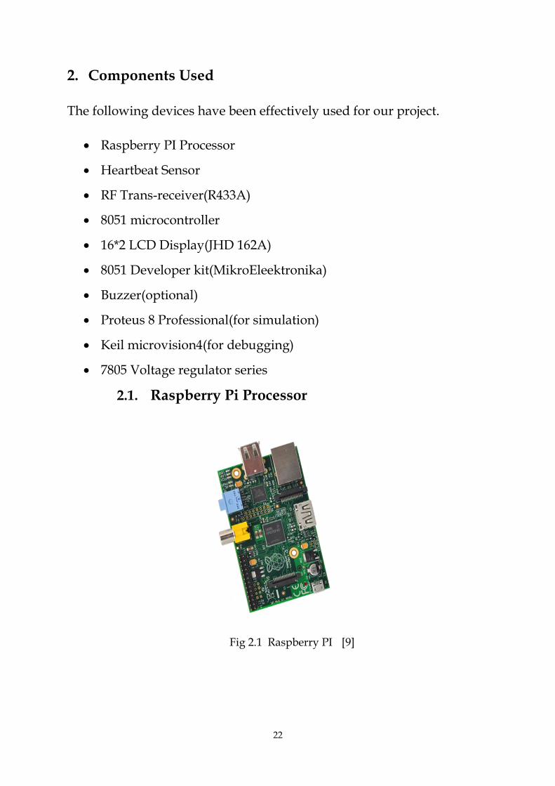
2.1. Raspberry Pi Processor
Fig 2.1 Raspberry PI [9]

23
The Raspberry Pi is a credit card sized single board computer. It was
developed by the Raspberry PI foundation in the UK to promote education in
schools.
The features and components of Raspberry PI are as follows:
Broadcom BCM8235 processor. It is a SOC(system-on-a chip) type processor
and also includes an ARM 700 MHz processor
256 megabytes of RAM. This was later upgrades to 512 MB
Uses a SD card for booting and storage
Contains USB ports, one HDMI (High Definition Multimedia Interface) port
and audio and video jacks
2.1.1 Pin Layout
The raspberry Pi has 26 pins on it to empower outside interchanges through
its pins. They are available in two columns of 13 pins each.
Along with the well-known USB, Ethernet and HDMI ports, the Raspberry-Pi
offers more level-level interfaces expected to unite all the more
straightforwardly with chips and subsystem modules. These GPIO (general
purpose I/O) motions on the header pins incorporate SPI, I2c, serial UART,
3v3 and 5v power.
The behaviour of the GPIO pins can be regulated by software (MATLAB in
our case) which is present on the SERVER-PC.
Fig 2.2 Pin Layout of Raspberry PI [9]

24
2.2 HEARTBEAT SENSOR:-
The model of the heartbeat sensor which is used in this project is GLTS HBS 001.
Working principle:-
Heart beat sensor is designed to give digital waveform of the
heat beat when a finger is placed on in between the IR transmitter and receiver.
When the heart- beat detector is working condition, the beat LED flashes each time
in unison with the heart beat. This digital output can also connected to a
microcontroller to calculate the Beats Per Minute (BPM) rate. During the
compression of the heart, blood pumps towards the end of the finger, so the density
of blood increases, as a consequence the intensity of the light that is being received
by the IR receiver decreases, so corresponding a low signal is obtained. Similarly in
the time of expansion a high amplitude signal is obtained. This analog signal is
passed through an OP-AMP which is being used as a comparator. By carefully
setting the proper reference voltage of the op-amp a square pulse is generated, as
shown in the figure.
Fig 2.3 Circuit diagram for GLTS HBS 001

25
2.2.1 Specifications:
Table 2.1
Operating voltage +5V DC
Operating current 150 mA
Output data 5v TTL
Detection of heartbeat LED indication
Source of light 660nm super LED
Fig 2.4 Analog and digital output waveform of heartbeat
sensor

26
Fig 2.5 Heart beat sensor
2.2.2. FEATURES:-
High beat LED indication
Instant output digital signal
Compact in size
+5V working voltage

27
2.3. RF Module:-
The RF module used in this project is R433A,which operates at
a frequeny 433MHz.
Fig 2.6 R433A RF module
2.3.1. Pin Configuration:-
RF Transmitter-
Table 2.2

28
RF receiver-
Table 2.3
2.3.2. Working principle:-
A RF module is normally an electronic gadget used for transmitting
and receiving the radio signals between two gadgets. In Embedded systems, it is
necessary to communicate with an alternate gadget remotely. This wireless
communication may be done through Radio Frequency (RF) communication or
Optical communication. For some provisions the medium of choice is RF since it
doesn't need a line of sight.
The signal to be transmitted is fed through the DATA pin of the RF Tx
named “DATA”.This signal get transmitted to the destination through the wireless
channel at a carrier frequency of 433MHz.The signal then received at the receiving
stage has been processed for further operation accoring to the project.

29
2.3.3. RF Modulation:-
This are the common types of signal modulation that are being used in RF
transmission and reception.
ASK
FSK
OOK
Frequency Hopping spread Spectrum
Direct sequence spread spectrum
1. ASK:-
Amplitude-shift keying (ASK) is an amplitude modulation in
which that digital data is represented as change in the amplitude of
the carrier wave. In the ASK system, the binary symbol ‘1’ is
represented by transmitting a fixed-amplitude carrier signal and fixed
frequency for a bit time of T seconds. When the signal value is 1 then
there will be transmission of the carrier signal; otherwise, if the signal
value is 0,then the carrier wave will not be transmitted.
Fig 2.7 Amplitude Shift Keying
FSK:-
Frequency shift keying (FSK) is a modulation in which digital signal is
transmitted through discrete frequency variations of the carrier signal. The simplest

30
form of FSK is binary FSK (BFSK). BFSK uses a pair of discrete frequencies to
transmit the binary information. In this modulation, the "1" is represented as the
mark frequency and the "0" is represented as the space frequency.
Fig 2.8 Signal representation of the FSK modulation

31
2.4. 8051 Microcontroller:-
Fig 2.9 Pin Layout
The Intel 8051 uC series is a Harvard architecture, CISC processor, single on-
chip microcontroller series which was developed by Intel in 1980 for extensive use
in embedded systems.

32
2.4.1. Features of 8051 series:-
8-bit ALU unit and an Accumulator, 8-bit Registers banks), 8-bit data bus.
Simple processor with 17 instructions, 1-bit accumulator, 32 registers and 144
special 1 bit-addressable RAM memory locations.
Multiplication, division and compare instruction sets.
4 fast register banks with memory mapped 8 registers .
Fast interrupt with optional register bank switching
Interrupts with predefined priority rules.
Dual 16-bit address bus , 2 x 216 memory locations can be accessible ,64 Kb each
of ROM and RAM.
on-chip RAM -128 bytes
4 Kb ROM, with a 16-bit address bank (PMEM).
4 8-bit bi-directional I/O ports.
UART in serial communication
Two Very effective 16-bit Counter/timers, Timer 0 and Timer 1.
Power saver mode
2.4.2. Architecture of 8051:
Crystal clock
Port configuration
Internal Interrupt Structure
Timers and counters
Memory and Register Banks

33
2.4.3. Memory Organisation:-
Fig 2.10 Memory organisation of 8051 microcontroller
The memory organization for 8051 series is as shown in fig. above. 8051
microcontroller consists of an on chip internal ROM of 4K size and
whwnever necessary , we can add an external memory of size 60K.so total o f
64K memory is available for 8051 uC. By default, the External Access (EA)
pin is connected Vcc.Initially the instructions are fetched from internal
memory. When the internal limit of memory (4K) is crossed , control of
program will be automatically shifted to external memory and remaining
instructions will be fetched from external ROM. If only external memory is
needed i.e. to fetch instruction from external memory,then we have to
connect External Access (EA) pin to ground as shown in fig. above.
Crystal clock:-
The 8051 requires an external crystal oscillator circuit. The oscillator circuit
operates on 12MHz, although the 8051 has capability of running at a maximum of
40MHz. Each machine cycle in the 8051 uC is of 12 clock cycles, giving an cycle rate

34
at 1MHz (for 12MHz clock) to 3.33MHz (for maximum 40MHz clock). The oscillator
circuit generates the clock signals so that all the internal operations can be properly
synchronised.
Port configuration:-
Pins 1-8: Port 1 can be configured as an input or an output.
Pin 9: RS A logic ‘1’ on this pin disables the microcontroller and resets the contents
of most registers.. By applying logic 0 to this pin, the program will begin the
execution.
Pins10-17: Port 3 , each of these pins serves as general purposei nput or output.
Besides, all of them have special functions:
Pin 10: RXD,used for Serial asynchronous communication input and Serial
synchronous communication output.
Pin 11: TXD Serial asynchronous communication output or Serial synchronous
communication clock output.
Pin 12: INT0 input of Interrupt 0.
Pin 13: INT1 Interrupt 1 input.
Pin 14: T0 Counter 0 input.
Pin 15: T1 Counter 1 input.
Pin 16: WR Write to the external RAM.
Pin 17: RD Read from the external RAM.

35
Timers and Counters:-
Many microcontroller requires the count of external events, such as the frequency of
a pulse sequence, or the generation of exact internal time delays between computer
activities. This can be accomplished using software techniques, but software for
counting or timing occupies the processorfor a substantial amount of time, perhaps
more important, functions are not executed. To get rid of this burden, two 16-bit up
counters, named T0 and T1, are embedded for the general use of the programmer.
Each counter can be programmed for counting internal clock pulses, as a timer, or
programmed to count the external signals as a counter.
Timer is set by an 8 bit register commonly known as TMOD register.
gate c/t M1 M0 Gate c/t M1 M0
GATE-This bit is required for manually ON and OFF the timer through
hardware.
C/T-logic 1 on this implies The timer to be used as a counter and a logic 0 implies
the timer to be used a timer for delay generation.
M1,MO:-this two bits determines the mode on whichthe timer or the counter to
be operated.
The 1st 4 bits are effectively used for Timer 1 and the lower 4 bits are used for
Timer 0.

36
2.5. 8051 Developer kit(MikroElektronika):-
Fig 2.11 8051 Developer Kit
Easy8051 v6 development system is supported by a huge range of Atmel
8051 microcontrollers.
Fast, on-board USB 2.0 programmer with a simple driver installation
procedure.

37
Serial COG Display which uses SPI interface is available for displayof the
text messages.
Easy8051 v6 allows 8051 microcontrollers to interface with variety of
peripheral devices. The uC model used is AT89S8253.
On-board 16-bit I/O port expander MCP23S17 that uses SPI communication.
7-segment displays in multiplexing mode are connected to the uC socket.
All pins connected to the IDC10 connectors for further extension.
38 LEDs are used for the indication of the logic state of all microcontroller
pin.
Graphic LCD 128x64 can be easily interfaced through the on-board connector.
GLCD Contrast Potentiometer is used for the adjustment of graphical LCD
contrast.
All of the MCU pins are painted on the back of the kit. These marks provide
basic knowledge of the pins.
Fast, on-board USB 2.0 programmer. There is no requirement for connection
to the external programmer

38
2.6. 16*2 LCD display:-
The model of LCD used is JHD 162A.
ALCD is an even board, electronic visual showcase which utilizes the property of
light modulation of fluid crystals. Light cant be specifically emiited by fluid crystal.
The working of LCD rely on upon two sheets of polarizing material with a fluid
crystal result amidst them. At the point when an electric current is passed through
the fluid, it causes the crystals to adjust so it closes out light and does not permit it to
pass[ 10 ]. Every crystal carries on like a screen, it either permits light to pass
through or obstructs the light..
It can work legitimately in the temperature reach of -10℃ to 60℃ and has working
lifetime of longer than 50000 hours (at room temperature without immediate
irradiation of daylight.
Fig 2.12 LCD Display

39
LCD Block diagram:-
Fig 2.13 LCD Block Diagram
2.6.1. LCD Pin Configuration:-
Table 2.4
PIN NO. SYMBOL DESCRIPTION FUNCTION
1 VSS GROUND 0V (GND)
2 VCC POWER SUPPLY FOR
LOGIC CIRCUIT
+5V DC supply
3
VEE
LCD CONTRAST
4
RS
INSTRUCTION/DATA RS = 0 : Command register
5
R/W
READ/WRITE SELECTION
R/W = 0 : Write to the registers
6 E ENABLE High to low pulse
7 DB0
DATA INPUT/OUTPUT
LINES
8 BIT: DB0-DB7
8 DB1
9 DB2
10 DB3
11 DB4
12 DB5
13 DB6
14 DB7
15
LED+
SUPPLY VOLTAGE
LCD Backlight
+5V

40
CHAPTER 3
SYSTEM DESIGN
41
3. SYSTEM DESIGN
Here, we have first implemented a system using a Raspberry- PI processor.
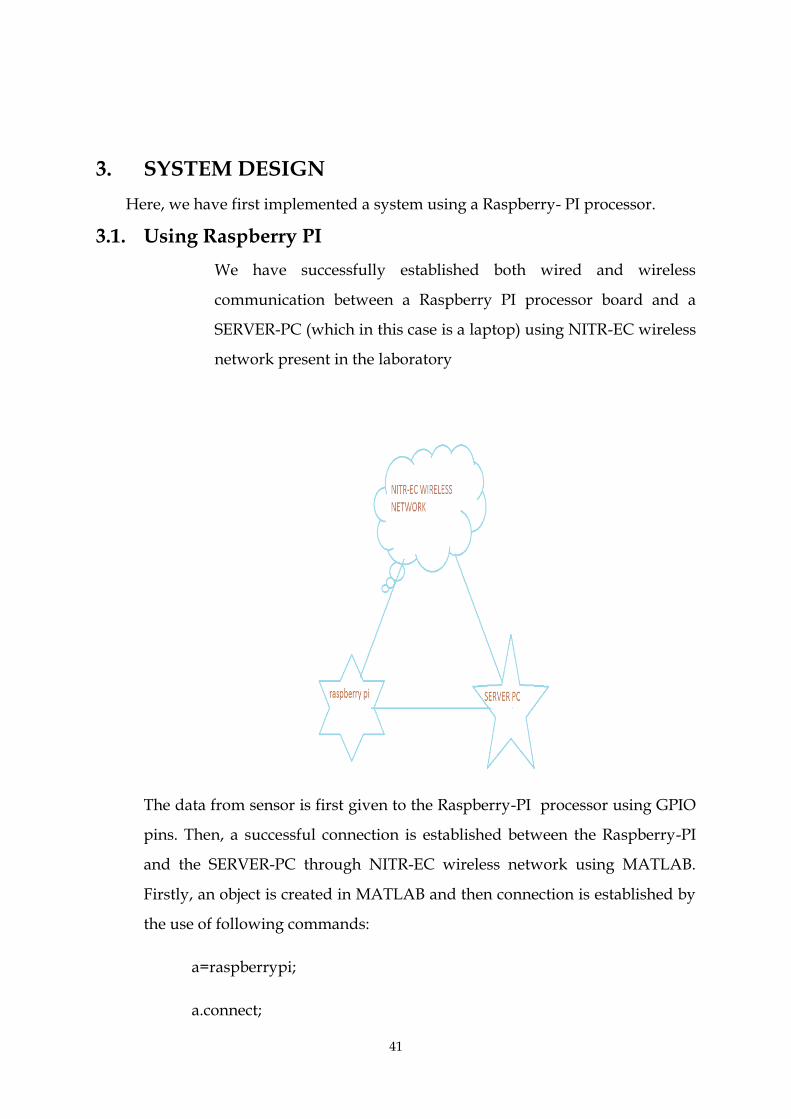
3.1. Using Raspberry PI
We have successfully established both wired and wireless
communication between a Raspberry PI processor board and a
SERVER-PC (which in this case is a laptop) using NITR-EC wireless
network present in the laboratory
The data from sensor is first given to the Raspberry-PI processor using GPIO
pins. Then, a successful connection is established between the Raspberry-PI
and the SERVER-PC through NITR-EC wireless network using MATLAB.
Firstly, an object is created in MATLAB and then connection is established by
the use of following commands:
a=raspberrypi;
a.connect;

42
3.2. System Design Using 8051 Microcontroller:-
Fig 3.1
3.2.1 Overall Functioning:-
First the communication between the human body and the heart beat sensor is
established. The completed working procedure of the heart beat sensor is explained
in the next section. According to the way the heart beats in the body, a square wave
pulse is obtained from the heart beat sensor. The square pulse is nothing but a
characteristic pulse with respect to the heartbeat. As the project is closely concerned
with the health care system, it is highly essential to synthesize a genuine procedure
to use this signal that is coming out of the human body in the field of medical
application. So the signal has been transmitted to some distant place using RF
communication, because the main objective of our project is to let the people around
the patient know about the real time condition of the patient and this is only possible
if the signal from the body through the heartbeat sensor is effectively transmitted to
the distant location where the concerned people are present.

43
In this way some life threatening accidents can be avoided by
providing real time medical attention to the patient(prone to heart attacks, cardio
vascular diseases) in case of emergency situation . For that, an RF wireless channel
has been established using an RF trans-receiver. Since he signal that is being
transmitted through the RF channel contains the information about the heart rate of
the patient’s body, it is essential to keep track of this signal in real-time. For this
purpose, an 8051 microcontroller is used.
The basic purpose of the micro controller is to count the pulses that are being
received through the RF channel in real-time and after a certain interval(which is
user defined ) it compares the counted value with the threshold value. In this case
the threshold value is defined as the maximum/minimum heart rate that a human
body can sustain without causing any substantial health hazards. If the counted
value is greater than the threshold value ,then an ALERT message is sent. In this
project the alert message is displayed through an LCD display , which continuously
displays appropriate message that has been programmed by the 8051
microcontroller.
3.2.2 Interfacing The heartbeat sensor with the body:-
For interfacing the Heart beat sensor,First the finger is inserted in between the IR
transmitter and receiver.The output signal obtained from sensor,is then passed
towards the OP Amp which is being used as acomparator.And a digital square
wave pulse is obtained according to the way the heart of the human beats.

44
Fig 3.2 Digital Ouput From the Heart Beat Sensor
3.2.3. Interfacing The Heart Beat Sensor with the RF
Transmitter:-
The signal thus obtained,as shown in the figure,is passed to the the
“DATA” pin of the RF Transmitter.In the Antenna Terminal,a 10-15 long metal wire
is established for the purpose of RF transmission.For testing Purpose,3 types of
signals is tranmitted.
A constant logic High Voltage
A square wave pulse,+5V DC,varibale frequency
The output of the Heart beat sensor

45
The +5V DC supply is provided through the Function Generator in the lab.In this
way a systematic approach has been made towards the execution of the Final
year Project.
Fig 3.3 R433A RF module
3.2.4. Communication in between RF transmitter and RF
Receiving stage:-
The signal which is transmitted by the RF Transmitter is received at the RF
receiving stage through the RF channel.As already explained in the previous
section,3 signals has been transmitted for the testing purpose.All the signals are
effectively received and processed for further operation.The signals are received
using ASK modulation,in which amplitude of the carrier signal changes according
the logic 1’s and 0’s in the digital signal.The Amplitude and Frequency of the both
transmitted and received signal are measured.The results of the following output are
briefly explained in the previous section.

46
3.2.5.Interface in between the 8051 and the RF transmitter:-
The digital signal signal that is being received at the RF receiver,is the
characteristic signal of the human heart rate.The number of pulses in the digital
pulse train is exactly equal to the the number of times the heart beats.So to use this
project effectively in human healthcare system,it is highly necessary that the number
of pulses in the signal to be regularly counted in real time.For that purpose,the 8051
microcontroller is used.In this case,The TMOD register which determines the mode
and type of timer circuit,is set to be 15H by settting the following expression.
TMOD=0x15; (in embedded C language)
That means the 8051 uC to be operated in the Counter 0 mode 1 and Timer 1 mode 1
mode.The input to the counter 0 is given through the pin P3.4,which is the external
counter output for Counter 0.In this case the P3.4 is connected to the RF receiving
terminal through which the signal from the heartbeat sensor is received.The Basic
job of Counter 1 is to give a certain time delay,within that period time the
microcontroller counts the number of pulses.If the no of pulses after the time delay is
less than the thresold value(maximum rate of heart beat that a human body can
sustain without having a substancial health hazard),then the 8051 uC instructs the
LCD to display a message that shows that the patient condition is normal,if it is
more than the thresold then the 8051 instructs the LCD to display an alert message
that has been programmmed by the 8051,to warn the the concerned people of the
patient.In this the thresold value is assumed to be 80 BPM,where BPM stands for
Beats Per Minute.So if the uC generates a delay of 10 secs,then the thresold value for
that 10 secs is believed to be 80/6=14.Hence at the end of each Program cycle,the
processor compares the counted value with 14 and correspondingly it generates the
display.

47
3.2.6. Interface in between the LCD and the 8051
microcontroller:-
Fig 3.4 Interfacing between LCD and 8051
As shown in the diagram, the data pins of the LCD D0-D7 are connected to the Port
0.The RS pin is connected to the p2.0,the R/W pin is to the P2.1 and the EN pin to
the pin P2.3.Normally a high to low pulse is given to the LCD for transfer of the data
and command signals.The VCC,VSS and the VEE pins are connected as described in
the previous sections.
3.3. SOFTWARE MODULE:-
The Stimulation which is used in the this project is PROTEUS 8 PROFESSIONAL
and KEIL uVISION 4 for debugging.The follwing are the steps that are being used
for the successful software level implementation of project.
First a new project is created belonging the ATMEL 8051 series.
Then in the LAYOUT page,an 8051 uC is placed by selecting it from the
library,

48
Then an appropiate LCD is selected from the Library package and the
inteconnection are done according to the Circuit diagram as shown in the
above figure.
The program file which gets embedded on the 8051 uC,is created by the KEIL
software and the corresponding HEX file is created by it.
Then this HEX is loaded in to the 8051 in the LAYOUT page of the PROTEUS
software and the desired output are obtained.
The complete diagram and the results are briefly explained in the next section.

49
CHAPTER 4
RESULTS AND DISCUSSION

50
4.1 RESULTS AND DISCUSSION:-
The results and the output of the Project is systematically explained ,stage by
stage,in the Following section.
4.1.1 Stage 1(Heart beat sensor):-
Fig 4.1 Heartbeat Sensor Output
The signal that is generated by the Heart Beat sensor is monitored by the
Oscilloscope and its frequency is found to be less than 10,which is obvious.The
number of pulses are exactly equal to the the number of times the human heart
beats.
4.1.2 STAGE 2(RF Transmitter):-The output of the Heartbeat sensor is connected to
the data pins of the RF transmitter.The output of the transmitter is tranmitted
through the RF channel using ASK modulation.

51
4.1.3 STAGE 3( RF Receiver):-
The transmitted signal is effectively received by the RF reciever.The following are
the outputs of the 3 test signal that are transmitted from RFTx.
1-Ideal Square wave pulse:-
Fig 4.2 Ideal Square Wave Pulse Output

52
2-Pulses from Heart beat sensor:-
Fig 4.3 RF transmitter and receiver output
The signals in yellow colour represents the signal that is transmitted from the
heartbeat sensor.
The signal in the green colour represents the the signal which is received at the RF
receiving stage.
The frequency of the Receiver and the transmitter is exactly same.The error in the
amplitude is +/- 5%.
4.1.4 STAGE 4(LCD Outputs):-
As per the number of pulses counted by the 8051 uC the LCD display messages
accordingly.If the number is less than the thresold number,then the LCD displays
the following message
Similarly if the number is greater the the thresold value the following output will be
displayed.

53
FIG 4.4 LCD OUTPUT
The Schematic output of The PROTEUS 8 is as follows
Fig 4.5 Schematic output of Proteas Software

54
CHAPTER 5
CONCLUSION AND FUTURE SCOPE
55
5. Conclusion
In this project, we have first successfully established both wired and
wireless communication between two machines- a Raspberry PI
processor board and a SERVER-PC.
Then, RF wireless communication was successfully established between
the human body (heart beat sensor) and the 8051 microcontroller
(machine).By doing so, we have implemented machine-to-machine
communication successfully between two machines.
Then, we obtained data from a heart beat sensor and successfully
transmitted the data to a microcontroller using a RF trans-receiver.The
microcontroller processes the data to obtain meaningful information out
of it.This, information is then displayed on a LCD screen and can be used
to sound an alarm system.
By using M2M communication, we can reduce human efforts
substantially and optimize the performance of machines.
Future Scope
Here, we have a used a heartbeat sensor that needs to be present with the
patient as well as the system. So, the mobility of the patient is restricted as a
result of this. To avoid this, a more sophisticated heartbeat sensor that can
be attached to the patient’s body with a strap or adhesive can be used and in
that case, the heartbeat sensor also needs to have an in-built RF transmission
system or Bluetooth system to transmit data to the microcontroller for
further processing.
Again, the range of transmission is limited to around 50 meters. We can
improve the range of this system by using a GSM module which can
increase the range of this system manifold. In GSM module, it is feasible to
transmit the data via mobile networks to cellular phones and devices and
this improves the performance of the system and makes it more faster and
reliable.

56
REFERENCES
[1] J. Höller, V. Tsiatsis, C. Mulligan, S. Karnouskos, S. Avesand, D. Boyle: From
Machine-to-Machine to the Internet of Things: Introduction to a New Age of
Intelligence
[2] Sang-Joong Jung, Risto Myllylä, and Wan-Young Chung, Member, IEEE,
“Wireless Machine-to-Machine Healthcare Solution Using Android Mobile Devices
in Global Networks”, IEEE SENSORS JOURNAL, VOL. 13, NO. 5, MAY 2013
[3] Geng Wu, Shilpa Talwar, Kerstin Johnsson, Nageen Himayat, and Kevin D.
Johnson, Intel, “M2M: From Mobile to Embedded Internet”, IEEE Communications
Magazine April 2011
[4] G. Z. Yang, Body Sensor Networks, 1st ed. London: Springer-Verlag,2006,
[5] P. S. Pandian, K. Mohanavelu, K. P. Safeer, T. M. Kotresh, D. T. Shakunthala, P.
Gopal, and V. C. Padaki, “Smart vest: Wearable multiparameter remote
physiological monitoring system,” Med. Eng. Phys., vol. 30, no. 4, pp. 466–477, May
2008.
[4] T. Yilmaz, R. Foster, and Y. Hao, “Detecting vital signs with wearable wireless
sensors,” Sensors, vol. 10, no. 12, pp. 10837–10862, Dec. 2010.
[5] B. Massot, N. Baltenneck, C. Gehin, A. Dittmar, and E. McAdams, “EmoSense:
An ambulatory device for the assessment of ANS activityapplication in the objective
evaluation of stress with the blind,” IEEE Sensors J., vol. 12, no. 3,, Mar. 2012.
[6] Y. T. Chen, I. C. Hung, M. W. Huang, C. J. Hou, and K. S. Cheng, “Physiological
signal analysis for patients with depression,” in Proc. 4th Int. Conf. Biomed. Eng.
Informat., Shanghai, China, 2011.
[7] T. Taleb, D. Bottazzi, and N. Nasser, “A novel middleware solution to improve
ubiquitous healthcare systems aided by affective information,” IEEE Trans. Inf.
Technol. Biomed., vol. 14, no. 2,Mar. 2010.
[8] W. Y. Chung, C. Yau, K. S. Shin, and R. Myllylä, “A cell phone based health
monitoring system with self-analysis processor using wireless sensor network
technology,” in Proc. 29th Annu. Int. Conf. Eng. Med. Biol. Soc., Lyon, France, 2007.
[9] http://www.raspberrypi.org
57
[10] C. Kim, A. Soong, M. Tseng, and X. Zhixian, “Global wireless machine-to-
machine standardization,” IEEE Internet Comput., vol. 15, no. 2,Mar.–Apr. 2011.
[11] S. Whitehead, “Adopting wireless machine-to-machine technology,”Comput.
Control Eng., vol. 15, no. 5, Oct. 2004.
[12] C. Inhyok, Y. Shah, A. U. Schmidt, A. Leicher, and M. V. Meyerstein, “Trust in
M2M communication,” IEEE Veh. Technol. Mag., vol. 4, no. 3,, Sep. 2009.
[13] Z. Shelby and C. Bormann, 6LoWPAN: The Wireless Embedded Internet. New York:
Wiley, 2009.
[14] W. Shen, Y. Xu, D. Xie, T. Zhang, and A. Johansson, “Smart border routers for e-
healthcare wireless sensor networks,” in Proc. 7th Int. Conf. Wireless Commun., Netw.
Mobile Comput., Wuhan, China, 2011.
[15] A. J. Jara, M. A. Zamora, and A. F. G. Skarmeta, “An architecture based on
internet of things to support mobility and security in medical environments,” in
Proc. 7th IEEE Consumer Commun. Netw. Conf., Las Vegas, NV, 2010
[16] S. H. Toh, S. C. Lee, and W. Y. Chung, “WSN based personal mobile
physiological monitoring and management system for chronic disease,” in Proc. 3rd
Int. Conf. Convergence Hybrid Inf. Technol., Busan, Korea,2008.