application of moka methodology in generative model
TRANSCRIPT
ARTICLE IN PRESS
0952-1976/$ - se
doi:10.1016/j.en
E-mail addr
Engineering Applications of Artificial Intelligence 20 (2007) 677–690
www.elsevier.com/locate/engappai
Application of MOKA methodology in generative modelcreation using CATIA
Wojciech Skarka
Department of Fundamentals of Machinery Design, Silesian University of Technology, Konarskiego 18a, 44–100 Gliwice, Poland
Received 9 November 2006; accepted 20 November 2006
Available online 30 January 2007
Abstract
The paper presents the method of generative model creation in CATIA system. The method covers not only the very process of model
creation in CATIA system but also the whole complexity of the process, beginning with knowledge identification and acquisition and
finally with explanation system creation that facilitates and justifies the usage of generative model itself. The method, in one of its parts,
uses MOKA methodology and in particular its informal knowledge model and knowledge representation for generative model, which is
special for CATIA.
r 2006 Elsevier Ltd. All rights reserved.
Keywords: Generative model; Knowledge-based engineering; Knowledge representation; CATIA; Knowledge acquisition; Protege; Integrated design
1. Introduction
Currently, computer aided design (CAD)/CAM/CAEsystems are commonly used in designing in a form ofseparate programs or integrated systems. ContemporaryCAD systems usually use technologies that quite recentlyformed novelty e.g. parameterization, solid and surfacemodeling, virtual prototyping, etc. At the present phase ofdevelopment of these systems, the main focus of interestlies in the knowledge application in designing that wouldallow further improvement in designing process anddesigning object—knowledge-based engineering (KBE).By definition (Stokes, 2001), KBE system is a usage ofsuitable computer software for acquiring and reusingknowledge on a product and process in a possibly mostintegrated way. The usage of KBE systems is naturallyconnected with reusing of knowledge that has beenobtained from previous projects. Therefore, it is especiallybeneficial in the case of routine designing, design family ordesigns that is successive in the natural product develop-ment.
Routine designing constitutes one of the basic categoriesof designing. It is mainly based on repeated actions that
e front matter r 2006 Elsevier Ltd. All rights reserved.
gappai.2006.11.019
ess: [email protected].
form a backbone of a given group of designing processes(designing processes are understood as work on projectswithin one company, which can be allocated to the samefamily e.g. designing of various tooth gearboxes).Tasks that are done in a routine way generally do not
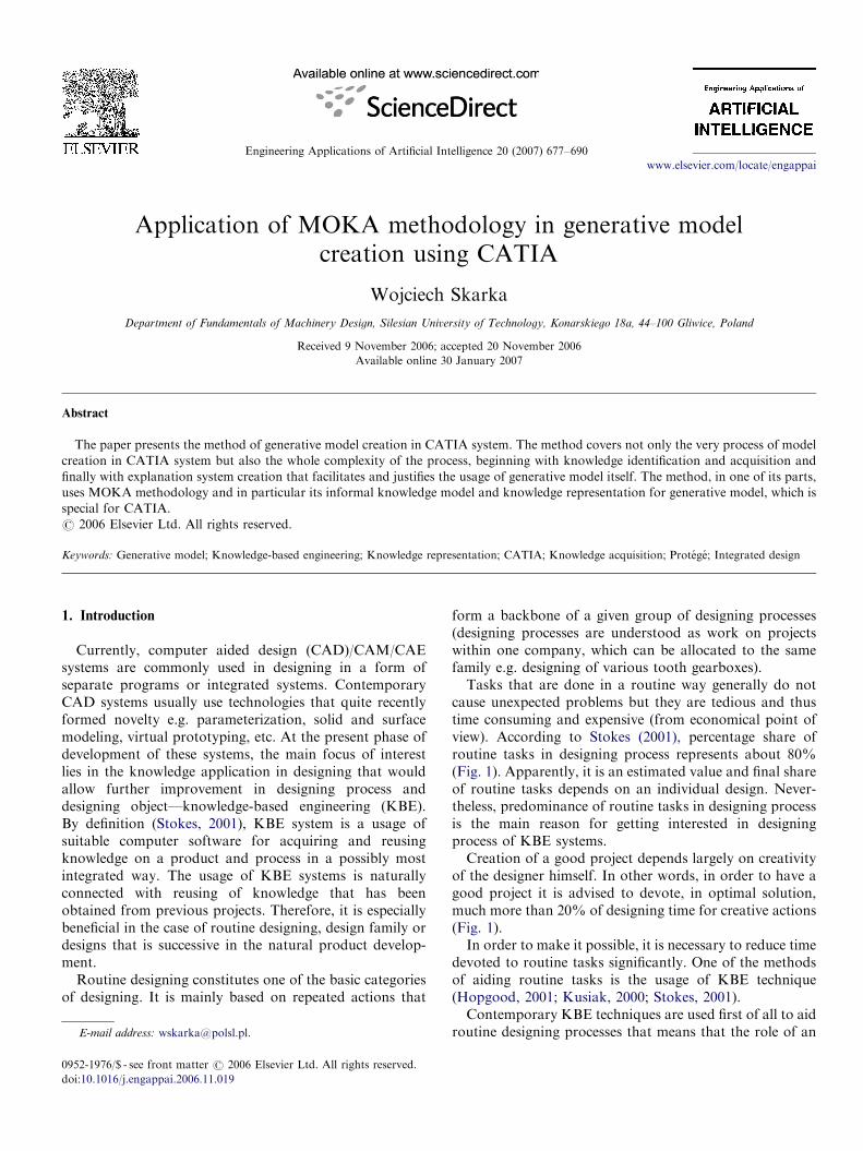
cause unexpected problems but they are tedious and thustime consuming and expensive (from economical point ofview). According to Stokes (2001), percentage share ofroutine tasks in designing process represents about 80%(Fig. 1). Apparently, it is an estimated value and final shareof routine tasks depends on an individual design. Never-theless, predominance of routine tasks in designing processis the main reason for getting interested in designingprocess of KBE systems.Creation of a good project depends largely on creativity
of the designer himself. In other words, in order to have agood project it is advised to devote, in optimal solution,much more than 20% of designing time for creative actions(Fig. 1).In order to make it possible, it is necessary to reduce time
devoted to routine tasks significantly. One of the methodsof aiding routine tasks is the usage of KBE technique(Hopgood, 2001; Kusiak, 2000; Stokes, 2001).Contemporary KBE techniques are used first of all to aid
routine designing processes that means that the role of an
ARTICLE IN PRESS
Fig. 1. Influence of KBE usage on time of main design tasks.
W. Skarka / Engineering Applications of Artificial Intelligence 20 (2007) 677–690678
engineer in a designing process has not been diminished butonly the scope of tasks has been changed, which results inradical change in the amount of time devoted to innovativeand creative actions. Assumption that (y) usage of KBEtechniques will never substitute human actions (Stokes,2001) is one of the fundamental assumptions of KBEsystems creators.
It is obvious that a scope of KBE techniques is in a waylimited. Here are some reasons that stand behind useless-ness of KBE techniques in some circumstances (Guida andTasso, 1994; Stokes, 2001):
�
it is not possible to isolate and define particular phasesof designing process, � constantly changing production technologies, � knowledge on a product or process is for some reasonnon accessible,
� problem is simple enough to solve it in a simpler waywithout KBE techniques,
� a company does not want to or cannot or has no need toimplement KBE techniques.
Despite studies carried toward formal application ofknowledge in designing process, few complex solutions ofKBE systems integrating methodical application of knowl-edge with modern functions of CAD systems (Sandberg,2003; Revelle et al., 1998) have been created. On the otherhand, there is a large group of CAD systems that haverelatively big possibilities for representation and knowledgerecord in a form of ready-for-use functions. Nevertheless,the main assumption for their application is correctlyidentified and obtained knowledge connected with parti-cular processes and their rules, structural and functional
entities of the designer product and their constraints. Thelack of integrated methods of knowledge identification,obtaining and storing in the system, which would later beused in a formal way, constitutes the main obstacle for theapplication of these functions. CATIA (Skarka andMazurek, 2005) can serve as an example here.
2. Knowledge representation in CATIA system
CATIA system has module structure with specializedfunctions grouped in module. Knowledgeware moduleforms a specialized module grouping functions connectedwith knowledge and allowing to expand design featureswith knowledge elements. It has some submodules and themost important of these are:
�
knowledge advisor, � knowledge expert, � product knowledge template, � business process knowledge template.They comprise many functions that allow automation ofthe choice of design features with the use of different formsof knowledge representation by ready made tools:
�
Parameters—basic tool to parameterize a component. � External parameters—to reference features of separateparts.
� Published parameters—defining relations at the assem-bly level between parameters (similar to constraints).
� Formulas—to reference features in form of formulas. � Design tables—to determine dimensional families ofproduct.
� Rules and checks—to implement determining productfeatures in conditional way to match rules relevant tothe company practices.
� Power copy, user features, document template—enablereuse of entities of product.
� Reactions—which can add a behavior to a component. � Sets of equations—to solve equations and inequalities � Scripts.Additionally, there is a possibility to use extra programtools (CAA RADE, 2006) for model extension created inCATIA system to a generative model.
2.1. Generative model
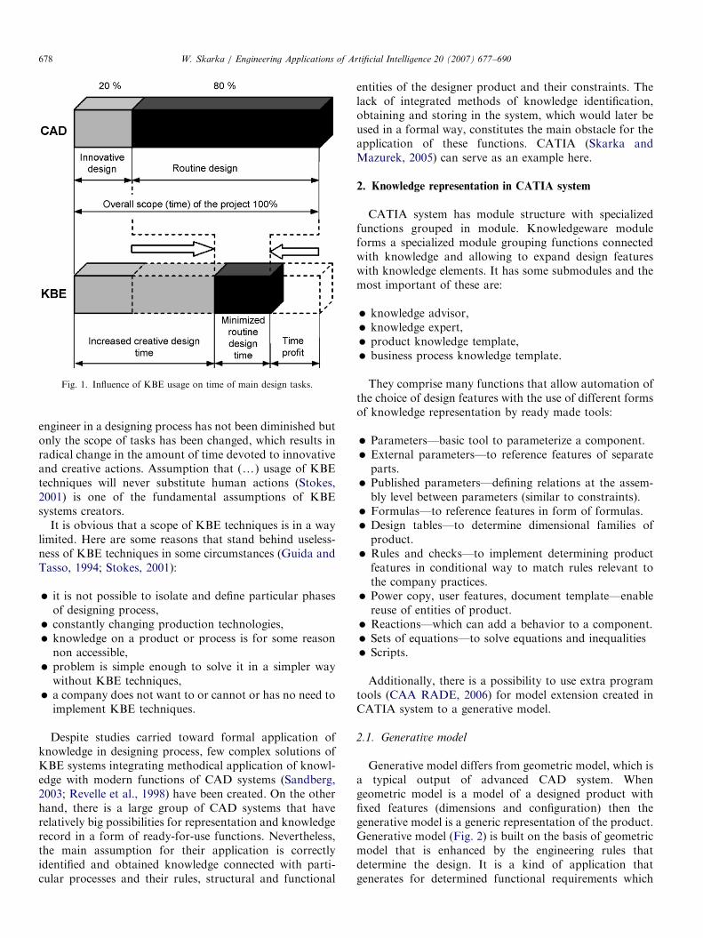
Generative model differs from geometric model, which isa typical output of advanced CAD system. Whengeometric model is a model of a designed product withfixed features (dimensions and configuration) then thegenerative model is a generic representation of the product.Generative model (Fig. 2) is built on the basis of geometricmodel that is enhanced by the engineering rules thatdetermine the design. It is a kind of application thatgenerates for determined functional requirements which
ARTICLE IN PRESS
Fig. 2. Generative model.
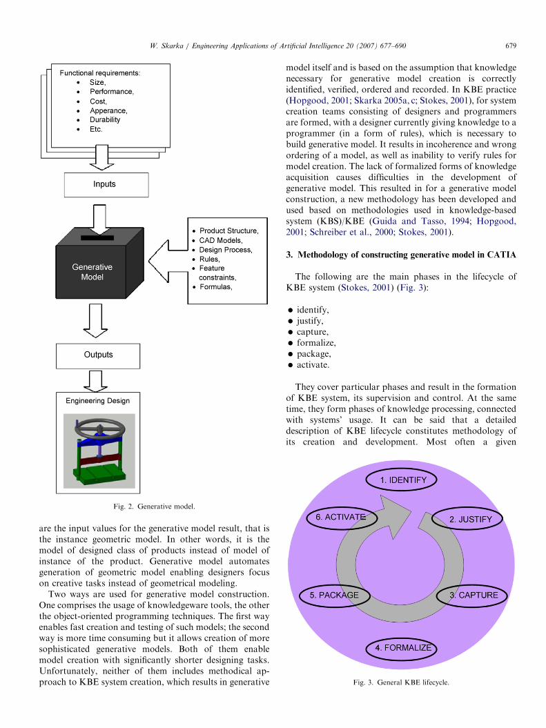
Fig. 3. General KBE lifecycle.
W. Skarka / Engineering Applications of Artificial Intelligence 20 (2007) 677–690 679
are the input values for the generative model result, that isthe instance geometric model. In other words, it is themodel of designed class of products instead of model ofinstance of the product. Generative model automatesgeneration of geometric model enabling designers focuson creative tasks instead of geometrical modeling.
Two ways are used for generative model construction.One comprises the usage of knowledgeware tools, the otherthe object-oriented programming techniques. The first wayenables fast creation and testing of such models; the secondway is more time consuming but it allows creation of moresophisticated generative models. Both of them enablemodel creation with significantly shorter designing tasks.Unfortunately, neither of them includes methodical ap-proach to KBE system creation, which results in generative
model itself and is based on the assumption that knowledgenecessary for generative model creation is correctlyidentified, verified, ordered and recorded. In KBE practice(Hopgood, 2001; Skarka 2005a, c; Stokes, 2001), for systemcreation teams consisting of designers and programmersare formed, with a designer currently giving knowledge to aprogrammer (in a form of rules), which is necessary tobuild generative model. It results in incoherence and wrongordering of a model, as well as inability to verify rules formodel creation. The lack of formalized forms of knowledgeacquisition causes difficulties in the development ofgenerative model. This resulted in for a generative modelconstruction, a new methodology has been developed andused based on methodologies used in knowledge-basedsystem (KBS)/KBE (Guida and Tasso, 1994; Hopgood,2001; Schreiber et al., 2000; Stokes, 2001).
3. Methodology of constructing generative model in CATIA
The following are the main phases in the lifecycle ofKBE system (Stokes, 2001) (Fig. 3):
�
identify, � justify, � capture, � formalize, � package, � activate.They cover particular phases and result in the formationof KBE system, its supervision and control. At the sametime, they form phases of knowledge processing, connectedwith systems’ usage. It can be said that a detaileddescription of KBE lifecycle constitutes methodology ofits creation and development. Most often a given
ARTICLE IN PRESS
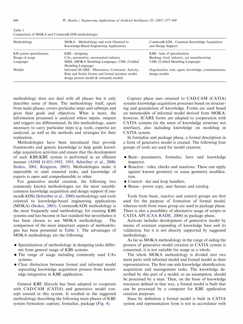
Table 1
Comparison of MOKA and CommonKADS methodologies
Methodology MOKA—Methodology and tools Oriented to
Knowledge-Based Engineering Applications
CommonKADS—Common Knowledge Acquisition
and Design Support
KB system specialization KBE—designing KBS—lack of specialization
Range of usage CAx, automotive, aeronautical industry Banking, food, industry, car manufacturing
Languages MML (MOKA Modeling Language), UML (Unified
Modeling Language)
UML (Unified Modeling Language)
Models Informal (ICARE—Illustration, Constraint, Activity,
Rule and Entity forms) and formal (product model,
design process model & rationale) models
Organization, task, agent, knowledge, communication,
design models
W. Skarka / Engineering Applications of Artificial Intelligence 20 (2007) 677–690680
methodology does not deal with all phases but it onlydescribes some of them. The methodology itself, apartfrom main phases, covers particular steps and substeps andgives their goals and objectives. What is more, theinformation processed is analyzed where inputs, outputsand triggers are differentiated. In this methodology, assetsnecessary to carry particular steps (e.g. tools, experts) areanalyzed, as well as the methods and strategies for theirrealization.
Methodologies have been introduced that provideframeworks and generic knowledge to help guide knowl-edge acquisition activities and ensure that the developmentof each KBS/KBE system is performed in an efficientmanner (ANSI G-031-1992, 1993, Schreiber et al., 2000;Stokes, 2001; Kingston, 2005). Methodologies make itimpossible to omit essential tasks, and knowledge ofexperts is open and comprehensible to other.
For generative model creation, the following twocommonly known methodologies are the most suitable:common knowledge acquisition and design support (Com-monKADS) (Schreiber et al., 2000) methodology and toolsoriented to knowledge-based engineering applications(MOKA) (Stokes, 2001). CommonKADS methodology isthe most frequently used methodology for creating KBSsystems and has become in fact standard but nevertheless ithas been chosen to use MOKA methodology . Thecomparison of the most important aspects of methodolo-gies has been presented in Table 1. The advantages ofMOKA methodology are the following:
�
Specialization of methodology in designing tasks differ-ent from general usage of KBS systems. � The range of usage including commonly used CAxsystems.
� Clear distinction between formal and informal modelseparating knowledge acquisition process from knowl-edge integration in KBE application.
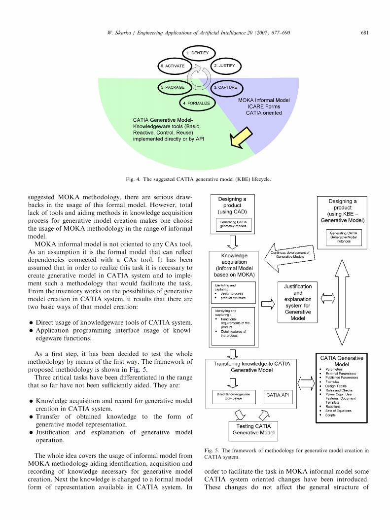
General KBE lifecycle has been adapted to cooperatewith CAD/CAM (CATIA) and generative model con-cept created in this system. It resulted in the suggestedmethodology describing the following main phases of KBEsystem formation: capture, formalize, package (Fig. 4).
Capture phase uses oriented to CAD/CAM (CATIA)systems knowledge acquisition processes based on structur-ing and granulation of knowledge. Forms are used basedon metamodels of informal model derived from MOKA;however, ICARE forms are adapted to cooperation withCATIA systems (in the sense of knowledge structure notinterface), also including knowledge on modeling inCATIA system.In formalize and package phase, a formal description in
a form of generative model is created. The following fourgroups of tools are used for model creation:
�
Basic—parameters, formulas, laws and knowledgeinspector. � Reactive—rules, checks and reactions. These can applyagainst known geometry or cause geometry modifica-tion.
� Control—list and loop handlers. � Reuse—power copy, user feature and catalog.Tools from basic, reactive and control groups are firstused for the purpose of formation of formal model,whereas tools from reuse group are used in package phase.There is also a possibility of alternative usage of scripts orCATIA API (CAA RADE, 2006) in package phase.Activate includes development of generative model by
means of constant expanding of knowledge base and itsvalidation, but it is not directly supported by suggestedmethodology.As far as MOKA methodology in the range of aiding the
process of generative model creation in CATIA system isconcerned, it is not suitable for usage as a whole.The whole MOKA methodology is divided into two
main parts with informal model and formal model as theirrepresentatives. The first one aids knowledge identification,acquisition and management tasks. The knowledge de-scribed by this part of a model, as an assumption, shouldbe processed by a man. Then, on the basis of knowledgeresources defined in that way, a formal model is built thatcan be processed by a computer for KBE applicationcreation purposes.Since by definition a formal model is built in CATIA
system and representation form is not in accordance with
ARTICLE IN PRESS
Fig. 4. The suggested CATIA generative model (KBE) lifecycle.
W. Skarka / Engineering Applications of Artificial Intelligence 20 (2007) 677–690 681
suggested MOKA methodology, there are serious draw-backs in the usage of this formal model. However, totallack of tools and aiding methods in knowledge acquisitionprocess for generative model creation makes one choosethe usage of MOKA methodology in the range of informalmodel.
MOKA informal model is not oriented to any CAx tool.As an assumption it is the formal model that can reflectdependencies connected with a CAx tool. It has beenassumed that in order to realize this task it is necessary tocreate generative model in CATIA system and to imple-ment such a methodology that would facilitate the task.From the inventory works on the possibilities of generativemodel creation in CATIA system, it results that there aretwo basic ways of that model creation:
�
Direct usage of knowledgeware tools of CATIA system. � Application programming interface usage of knowl-edgeware functions.
As a first step, it has been decided to test the wholemethodology by means of the first way. The framework ofproposed methodology is shown in Fig. 5.
Three critical tasks have been differentiated in the rangethat so far have not been sufficiently aided. They are:
�
Knowledge acquisition and record for generative modelcreation in CATIA system. � Transfer of obtained knowledge to the form ofgenerative model representation.
�Fig. 5. The framework of methodology for generative model creation in
CATIA system.
Justification and explanation of generative modeloperation.
The whole idea covers the usage of informal model fromMOKA methodology aiding identification, acquisition andrecording of knowledge necessary for generative modelcreation. Next the knowledge is changed to a formal modelform of representation available in CATIA system. In
order to facilitate the task in MOKA informal model someCATIA system oriented changes have been introduced.These changes do not affect the general structure of
ARTICLE IN PRESS
Fig. 6. MOKA informal model structure.
W. Skarka / Engineering Applications of Artificial Intelligence 20 (2007) 677–690682
informal model itself but complement it with attributesthat facilitate knowledge transfer to CATIA system. In thisidea, informal model representation constitutes an impor-tant task that guarantees free execution of changes inMOKA informal model and, additionally, it smoothlyfacilitates cooperation between a team of designers on thedevelopment of common knowledge base (filling in ICAREforms—illustration, constraint, activity, rule and entity)and allows informal model publication in a form thatenables the usage of these resources for justification andexplanation of generative model operation. It results ingreater designers’ confidence in the effects of generativemodel operation and also forms a kind of verification of itsoperation results.
To realize the suggested methodology, it was necessaryto
�
choose the base methodology (MOKA), � make precise inventory of knowledge representationforms in CATIA system,
� adapt informal model for the purposes of cooperationwith CATIA system,
� choose a form of representation of MOKA informalmodel,
� elaborate the method of justification of generativemodel,
� manage both informal and generative model so that itenables its constant development and improvement.
The most important of these tasks will be discussedbelow.
3.1. Adaptation of MOKA informal model for the purposes
of CATIA system
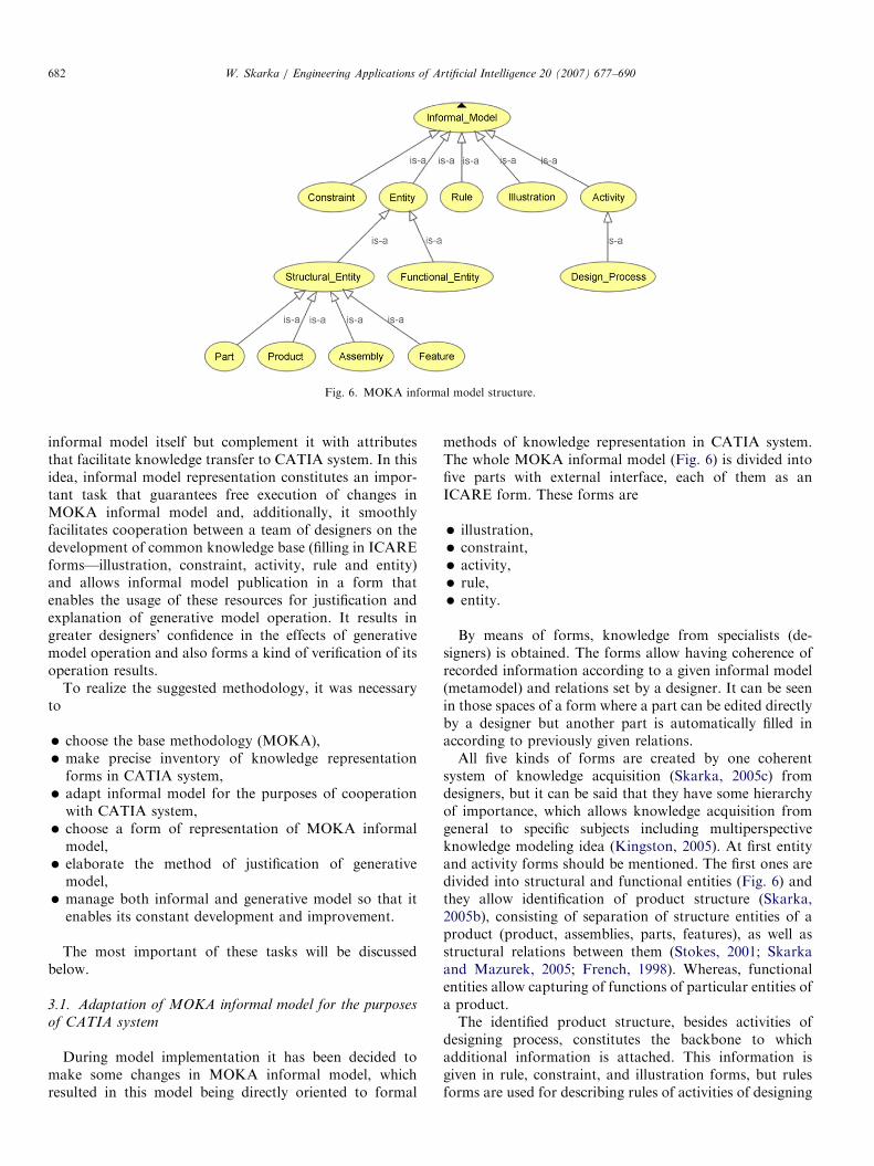
During model implementation it has been decided tomake some changes in MOKA informal model, whichresulted in this model being directly oriented to formal
methods of knowledge representation in CATIA system.The whole MOKA informal model (Fig. 6) is divided intofive parts with external interface, each of them as anICARE form. These forms are
�
illustration, � constraint, � activity, � rule, � entity.By means of forms, knowledge from specialists (de-signers) is obtained. The forms allow having coherence ofrecorded information according to a given informal model(metamodel) and relations set by a designer. It can be seenin those spaces of a form where a part can be edited directlyby a designer but another part is automatically filled inaccording to previously given relations.All five kinds of forms are created by one coherent
system of knowledge acquisition (Skarka, 2005c) fromdesigners, but it can be said that they have some hierarchyof importance, which allows knowledge acquisition fromgeneral to specific subjects including multiperspectiveknowledge modeling idea (Kingston, 2005). At first entityand activity forms should be mentioned. The first ones aredivided into structural and functional entities (Fig. 6) andthey allow identification of product structure (Skarka,2005b), consisting of separation of structure entities of aproduct (product, assemblies, parts, features), as well asstructural relations between them (Stokes, 2001; Skarkaand Mazurek, 2005; French, 1998). Whereas, functionalentities allow capturing of functions of particular entities ofa product.The identified product structure, besides activities of
designing process, constitutes the backbone to whichadditional information is attached. This information isgiven in rule, constraint, and illustration forms, but rulesforms are used for describing rules of activities of designing
ARTICLE IN PRESS
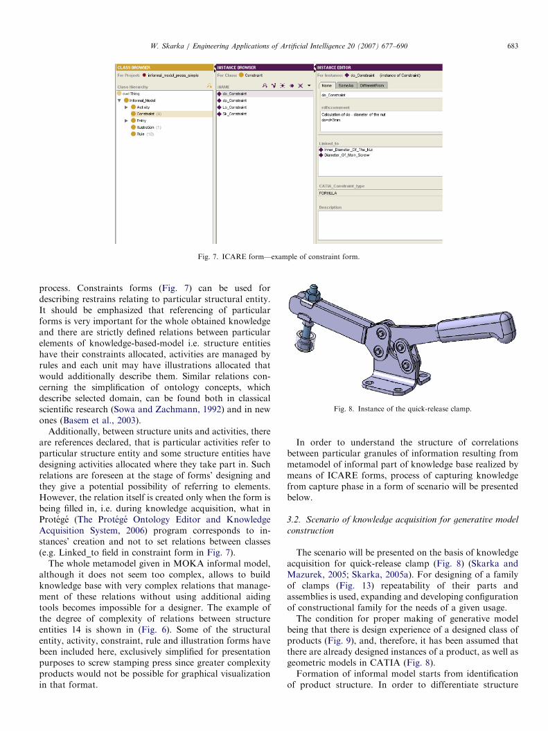
Fig. 7. ICARE form—example of constraint form.
Fig. 8. Instance of the quick-release clamp.
W. Skarka / Engineering Applications of Artificial Intelligence 20 (2007) 677–690 683
process. Constraints forms (Fig. 7) can be used fordescribing restrains relating to particular structural entity.It should be emphasized that referencing of particularforms is very important for the whole obtained knowledgeand there are strictly defined relations between particularelements of knowledge-based-model i.e. structure entitieshave their constraints allocated, activities are managed byrules and each unit may have illustrations allocated thatwould additionally describe them. Similar relations con-cerning the simplification of ontology concepts, whichdescribe selected domain, can be found both in classicalscientific research (Sowa and Zachmann, 1992) and in newones (Basem et al., 2003).
Additionally, between structure units and activities, thereare references declared, that is particular activities refer toparticular structure entity and some structure entities havedesigning activities allocated where they take part in. Suchrelations are foreseen at the stage of forms’ designing andthey give a potential possibility of referring to elements.However, the relation itself is created only when the form isbeing filled in, i.e. during knowledge acquisition, what inProtege (The Protege Ontology Editor and KnowledgeAcquisition System, 2006) program corresponds to in-stances’ creation and not to set relations between classes(e.g. Linked_to field in constraint form in Fig. 7).
The whole metamodel given in MOKA informal model,although it does not seem too complex, allows to buildknowledge base with very complex relations that manage-ment of these relations without using additional aidingtools becomes impossible for a designer. The example ofthe degree of complexity of relations between structureentities 14 is shown in (Fig. 6). Some of the structuralentity, activity, constraint, rule and illustration forms havebeen included here, exclusively simplified for presentationpurposes to screw stamping press since greater complexityproducts would not be possible for graphical visualizationin that format.
In order to understand the structure of correlationsbetween particular granules of information resulting frommetamodel of informal part of knowledge base realized bymeans of ICARE forms, process of capturing knowledgefrom capture phase in a form of scenario will be presentedbelow.
3.2. Scenario of knowledge acquisition for generative model
construction
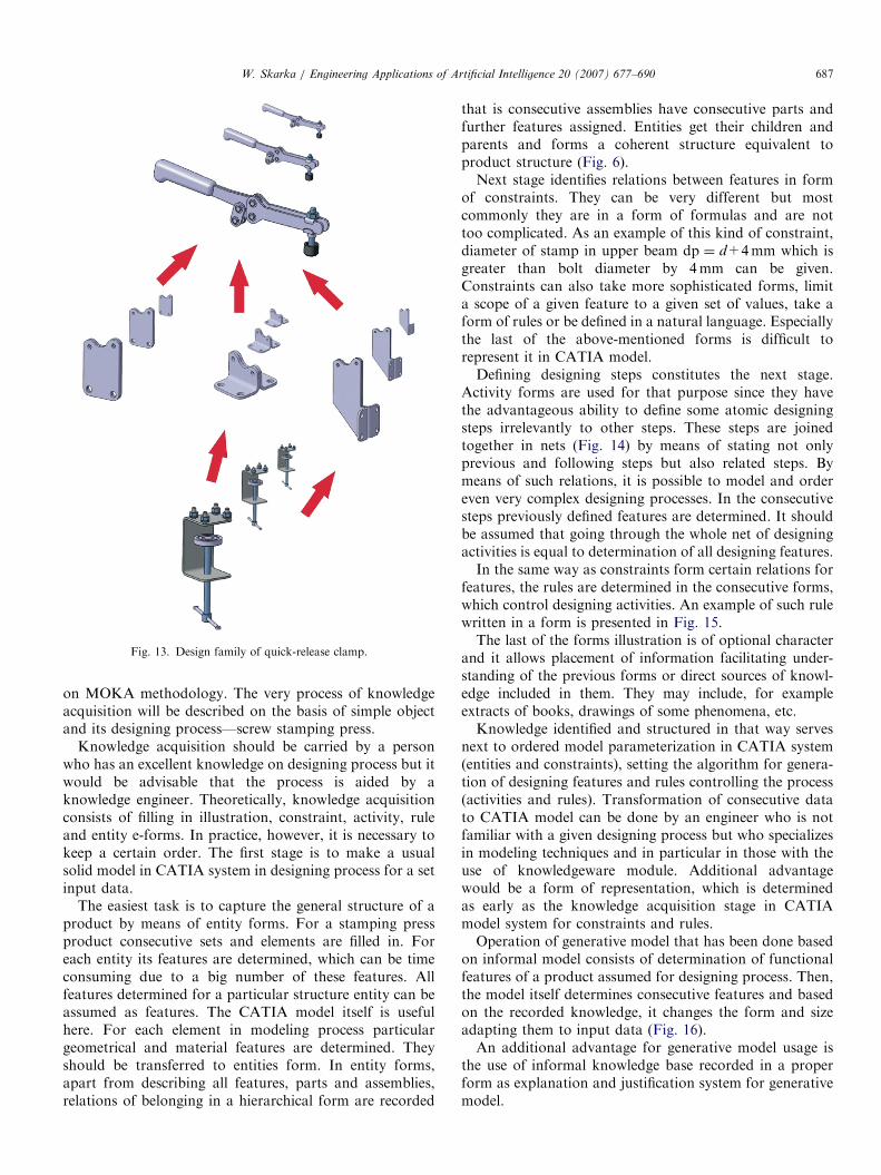
The scenario will be presented on the basis of knowledgeacquisition for quick-release clamp (Fig. 8) (Skarka andMazurek, 2005; Skarka, 2005a). For designing of a familyof clamps (Fig. 13) repeatability of their parts andassemblies is used, expanding and developing configurationof constructional family for the needs of a given usage.The condition for proper making of generative model
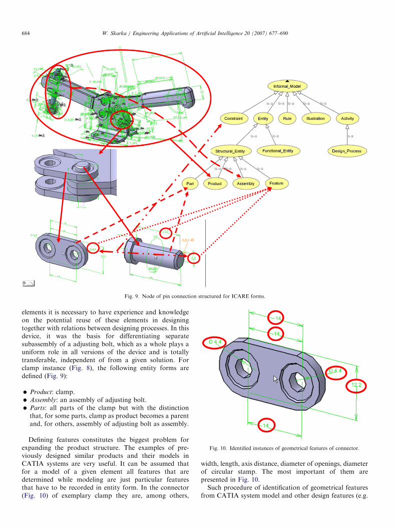
being that there is design experience of a designed class ofproducts (Fig. 9), and, therefore, it has been assumed thatthere are already designed instances of a product, as well asgeometric models in CATIA (Fig. 8).Formation of informal model starts from identification
of product structure. In order to differentiate structure
ARTICLE IN PRESS
Fig. 9. Node of pin connection structured for ICARE forms.
W. Skarka / Engineering Applications of Artificial Intelligence 20 (2007) 677–690684
elements it is necessary to have experience and knowledgeon the potential reuse of these elements in designingtogether with relations between designing processes. In thisdevice, it was the basis for differentiating separatesubassembly of a adjusting bolt, which as a whole plays auniform role in all versions of the device and is totallytransferable, independent of from a given solution. Forclamp instance (Fig. 8), the following entity forms aredefined (Fig. 9):
�
Product: clamp. � Assembly: an assembly of adjusting bolt. �Fig. 10. Identified instances of geometrical features of connector.
Parts: all parts of the clamp but with the distinctionthat, for some parts, clamp as product becomes a parentand, for others, assembly of adjusting bolt as assembly.
Defining features constitutes the biggest problem forexpanding the product structure. The examples of pre-viously designed similar products and their models inCATIA systems are very useful. It can be assumed thatfor a model of a given element all features that aredetermined while modeling are just particular featuresthat have to be recorded in entity form. In the connector(Fig. 10) of exemplary clamp they are, among others,
width, length, axis distance, diameter of openings, diameterof circular stamp. The most important of them arepresented in Fig. 10.Such procedure of identification of geometrical features
from CATIA system model and other design features (e.g.
ARTICLE IN PRESS
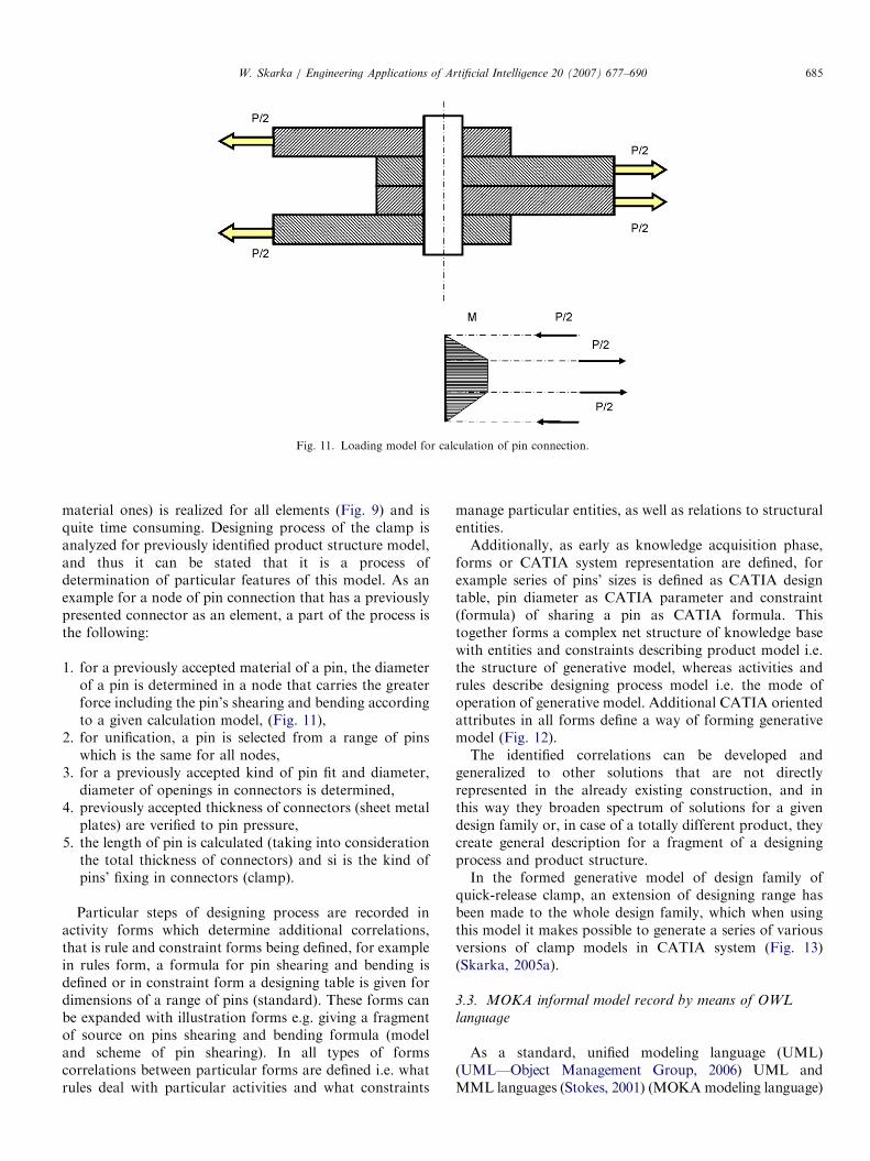
Fig. 11. Loading model for calculation of pin connection.
W. Skarka / Engineering Applications of Artificial Intelligence 20 (2007) 677–690 685
material ones) is realized for all elements (Fig. 9) and isquite time consuming. Designing process of the clamp isanalyzed for previously identified product structure model,and thus it can be stated that it is a process ofdetermination of particular features of this model. As anexample for a node of pin connection that has a previouslypresented connector as an element, a part of the process isthe following:
1.
for a previously accepted material of a pin, the diameterof a pin is determined in a node that carries the greaterforce including the pin’s shearing and bending accordingto a given calculation model, (Fig. 11),2.
for unification, a pin is selected from a range of pinswhich is the same for all nodes,3.
for a previously accepted kind of pin fit and diameter,diameter of openings in connectors is determined,4.
previously accepted thickness of connectors (sheet metalplates) are verified to pin pressure,5.
the length of pin is calculated (taking into considerationthe total thickness of connectors) and si is the kind ofpins’ fixing in connectors (clamp).Particular steps of designing process are recorded inactivity forms which determine additional correlations,that is rule and constraint forms being defined, for examplein rules form, a formula for pin shearing and bending isdefined or in constraint form a designing table is given fordimensions of a range of pins (standard). These forms canbe expanded with illustration forms e.g. giving a fragmentof source on pins shearing and bending formula (modeland scheme of pin shearing). In all types of formscorrelations between particular forms are defined i.e. whatrules deal with particular activities and what constraints
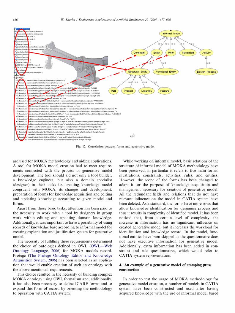
manage particular entities, as well as relations to structuralentities.Additionally, as early as knowledge acquisition phase,
forms or CATIA system representation are defined, forexample series of pins’ sizes is defined as CATIA designtable, pin diameter as CATIA parameter and constraint(formula) of sharing a pin as CATIA formula. Thistogether forms a complex net structure of knowledge basewith entities and constraints describing product model i.e.the structure of generative model, whereas activities andrules describe designing process model i.e. the mode ofoperation of generative model. Additional CATIA orientedattributes in all forms define a way of forming generativemodel (Fig. 12).The identified correlations can be developed and
generalized to other solutions that are not directlyrepresented in the already existing construction, and inthis way they broaden spectrum of solutions for a givendesign family or, in case of a totally different product, theycreate general description for a fragment of a designingprocess and product structure.In the formed generative model of design family of
quick-release clamp, an extension of designing range hasbeen made to the whole design family, which when usingthis model it makes possible to generate a series of variousversions of clamp models in CATIA system (Fig. 13)(Skarka, 2005a).
3.3. MOKA informal model record by means of OWL
language
As a standard, unified modeling language (UML)(UML—Object Management Group, 2006) UML andMML languages (Stokes, 2001) (MOKAmodeling language)
ARTICLE IN PRESS
Fig. 12. Correlation between forms and generative model.
W. Skarka / Engineering Applications of Artificial Intelligence 20 (2007) 677–690686
are used for MOKA methodology and aiding applications.A tool for MOKA model creation had to meet require-ments connected with the process of generative modeldevelopment. The tool should aid not only a tool builder,a knowledge engineer, but also a domain specialist(designer) in their tasks i.e. creating knowledge modelcongruent with MOKA, its changes and development,preparation of forms for knowledge acquisition and editingand updating knowledge according to given model andforms.
Apart from those basic tasks, attention has been paid tothe necessity to work with a tool by designers in groupwork within editing and updating domain knowledge.Additionally, it was important to have a possibility of usingrecords of knowledge base according to informal model forcreating explanation and justification system for generativemodel.
The necessity of fulfilling these requirements determinedthe choice of ontologies defined in OWL (OWL—WebOntology Language, 2006) for MOKA models record.Protege (The Protege Ontology Editor and KnowledgeAcquisition System, 2006) has been selected as an applica-tion that would enable creation of such an ontology withthe above-mentioned requirements.
This choice resulted in the necessity of building complexMOKA ontology using OWL formalism and, additionally,it has also been necessary to define ICARE forms and toexpand this form of record by orienting the methodologyto operation with CATIA system.
While working on informal model, basic relations of thestructure of informal model of MOKA methodology havebeen preserved, in particular it refers to five main forms:illustrations, constraints, activities, rules, and entities.However, the scope of the forms has been changed toadapt it for the purpose of knowledge acquisition andmanagement necessary for creation of generative model.All the redundant fields and relations that do not haverelevant influence on the model in CATIA system havebeen deleted. As a standard, the forms have more rows thatallow knowledge identification for designing process andthus it results in complexity of identified model. It has beennoticed that, from a certain level of complexity, theincrease in information has no significant influence oncreated generative model but it increases the workload foridentification and knowledge record. In the model, func-tional entities have been skipped as the questionnaire doesnot have executive information for generative model.Additionally, extra information has been added in con-straint and rule questionnaires, which would refer toCATIA system representation.
4. An example of a generative model of stamping press
construction
In order to test the usage of MOKA methodology forgenerative model creation, a number of models in CATIAsystem have been constructed and used after havingacquired knowledge with the use of informal model based
ARTICLE IN PRESS
Fig. 13. Design family of quick-release clamp.
W. Skarka / Engineering Applications of Artificial Intelligence 20 (2007) 677–690 687
on MOKA methodology. The very process of knowledgeacquisition will be described on the basis of simple objectand its designing process—screw stamping press.
Knowledge acquisition should be carried by a personwho has an excellent knowledge on designing process but itwould be advisable that the process is aided by aknowledge engineer. Theoretically, knowledge acquisitionconsists of filling in illustration, constraint, activity, ruleand entity e-forms. In practice, however, it is necessary tokeep a certain order. The first stage is to make a usualsolid model in CATIA system in designing process for a setinput data.
The easiest task is to capture the general structure of aproduct by means of entity forms. For a stamping pressproduct consecutive sets and elements are filled in. Foreach entity its features are determined, which can be timeconsuming due to a big number of these features. Allfeatures determined for a particular structure entity can beassumed as features. The CATIA model itself is usefulhere. For each element in modeling process particulargeometrical and material features are determined. Theyshould be transferred to entities form. In entity forms,apart from describing all features, parts and assemblies,relations of belonging in a hierarchical form are recorded
that is consecutive assemblies have consecutive parts andfurther features assigned. Entities get their children andparents and forms a coherent structure equivalent toproduct structure (Fig. 6).Next stage identifies relations between features in form
of constraints. They can be very different but mostcommonly they are in a form of formulas and are nottoo complicated. As an example of this kind of constraint,diameter of stamp in upper beam dp ¼ d+4mm which isgreater than bolt diameter by 4mm can be given.Constraints can also take more sophisticated forms, limita scope of a given feature to a given set of values, take aform of rules or be defined in a natural language. Especiallythe last of the above-mentioned forms is difficult torepresent it in CATIA model.Defining designing steps constitutes the next stage.
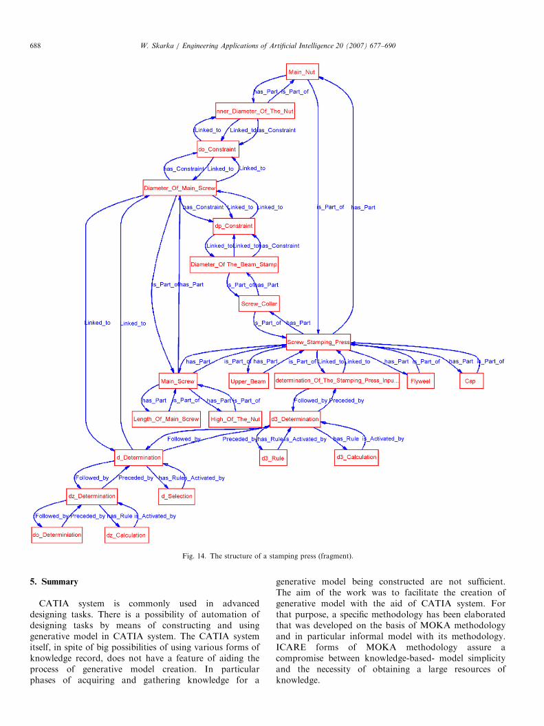
Activity forms are used for that purpose since they havethe advantageous ability to define some atomic designingsteps irrelevantly to other steps. These steps are joinedtogether in nets (Fig. 14) by means of stating not onlyprevious and following steps but also related steps. Bymeans of such relations, it is possible to model and ordereven very complex designing processes. In the consecutivesteps previously defined features are determined. It shouldbe assumed that going through the whole net of designingactivities is equal to determination of all designing features.In the same way as constraints form certain relations for
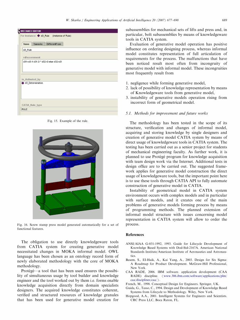
features, the rules are determined in the consecutive forms,which control designing activities. An example of such rulewritten in a form is presented in Fig. 15.The last of the forms illustration is of optional character
and it allows placement of information facilitating under-standing of the previous forms or direct sources of knowl-edge included in them. They may include, for exampleextracts of books, drawings of some phenomena, etc.Knowledge identified and structured in that way serves
next to ordered model parameterization in CATIA system(entities and constraints), setting the algorithm for genera-tion of designing features and rules controlling the process(activities and rules). Transformation of consecutive datato CATIA model can be done by an engineer who is notfamiliar with a given designing process but who specializesin modeling techniques and in particular in those with theuse of knowledgeware module. Additional advantagewould be a form of representation, which is determinedas early as the knowledge acquisition stage in CATIAmodel system for constraints and rules.Operation of generative model that has been done based
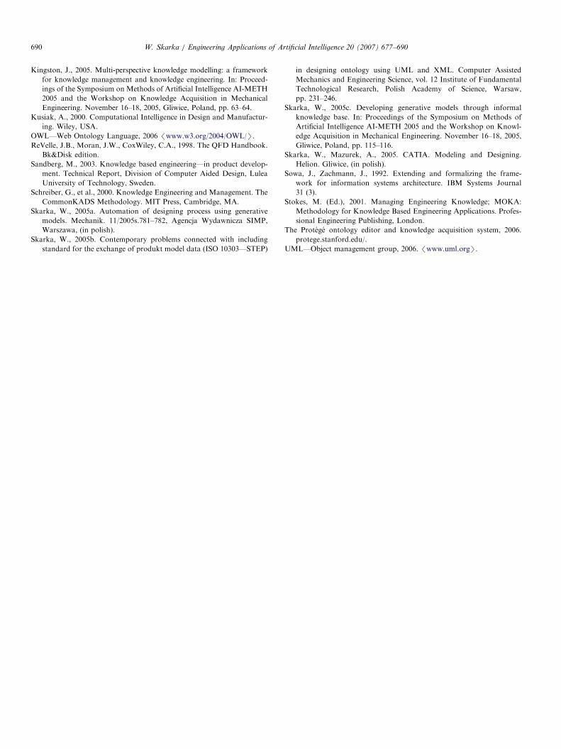
on informal model consists of determination of functionalfeatures of a product assumed for designing process. Then,the model itself determines consecutive features and basedon the recorded knowledge, it changes the form and sizeadapting them to input data (Fig. 16).An additional advantage for generative model usage is
the use of informal knowledge base recorded in a properform as explanation and justification system for generativemodel.
ARTICLE IN PRESS
Fig. 14. The structure of a stamping press (fragment).
W. Skarka / Engineering Applications of Artificial Intelligence 20 (2007) 677–690688
5. Summary
CATIA system is commonly used in advanceddesigning tasks. There is a possibility of automation ofdesigning tasks by means of constructing and usinggenerative model in CATIA system. The CATIA systemitself, in spite of big possibilities of using various forms ofknowledge record, does not have a feature of aiding theprocess of generative model creation. In particularphases of acquiring and gathering knowledge for a
generative model being constructed are not sufficient.The aim of the work was to facilitate the creation ofgenerative model with the aid of CATIA system. Forthat purpose, a specific methodology has been elaboratedthat was developed on the basis of MOKA methodologyand in particular informal model with its methodology.ICARE forms of MOKA methodology assure acompromise between knowledge-based- model simplicityand the necessity of obtaining a large resources ofknowledge.
ARTICLE IN PRESS
Fig. 15. Example of the rule.
Fig. 16. Screw stamp press model generated automatically for a set of
functional features.
W. Skarka / Engineering Applications of Artificial Intelligence 20 (2007) 677–690 689
The obligation to use directly knowledgeware toolsfrom CATIA system for creating generative modelnecessitated changes in MOKA informal model. OWLlanguage has been chosen as an ontology record form ofnewly elaborated methodology with the core of MOKAmethodology.
Protege—a tool that has been used ensures the possibi-lity of simultaneous usage by tool builder and knowledgeengineer and the tool worked out by them i.e. forms enableknowledge acquisition directly from domain specialistsdesigners. The acquired knowledge constitutes coherent,verified and structured resources of knowledge granulesthat has been used for generative model creation for
subassemblies for mechanical sets of lifts and press and, inparticular, bolt subassemblies by means of knowledgewaretools in CATIA system.Evaluation of generative model operation has positive
influence on ordering designing process, whereas informalmodel constitutes representation of full articulation ofrequirements for the process. The malfunctions that havebeen noticed result most often from incongruity ofgenerative model with informal model. These incongruitiesmost frequently result from
1.
negligence while forming generative model, 2. lack of possibility of knowledge representation by meansof Knowledgeware tools from generative model,
3. instability of generative models operation rising fromincorrect form of geometrical model.
5.1. Methods for improvement and future works
The methodology has been tested in the scope of itsstructure, verification and changes of informal model,acquiring and storing knowledge by single designers andcreation of generative model CATIA system by means ofdirect usage of knowledgeware tools in CATIA system. Thetesting has been carried out as a senior project for studentsof mechanical engineering faculty. As further work, it isplanned to use Protege program for knowledge acquisitionwith team design work via the Internet. Additional tests indesign office are to be carried out. The suggested frame-work applies for generative model construction the directusage of knowledgeware tools, but the important point hereis to use these tools through CATIA API to fully automateconstruction of generative model in CATIA.Instability of geometrical model in CATIA system
environment occurs with complex models and in particularwith surface models, and it creates one of the mainproblems of generative models forming process by meansof programming methods. The planned extension ofinformal model structure with issues concerning modelrepresentation in CATIA system will allow to order theprocess.
References
ANSI/AIAA G-031-1992, 1993. Guide for Lifecycle Development of
Knowledge Based Systems with Dod-Std-2167A. American National
Standards Institute/American Institute of Aeronautics and Astronau-
tics.
Basem, S., EI-Haik, A., Kai Yang, A., 2003. Design for Six Sigma:
A Roadmap for Product Development. McGraw-Hill Professional,
New York.
CAA RADE, 2006. IBM software. application development (CAA
RADE) discipline. /www.306.ibm.com/software/applications/plm/
caa/disciplines/caa/S.
French, M., 1998. Conceptual Design for Engineers. Springer, UK.
Guida, G., Tasso, C., 1994. Design and Development of Knowledge Based
Systems from Lifecycle to Methodology. Wiley, New York.
Hopgood, A.A., 2001. Intelligent Systems for Engineers and Scientists.
CRC Press LLC, Boca Raton, FL.
ARTICLE IN PRESSW. Skarka / Engineering Applications of Artificial Intelligence 20 (2007) 677–690690
Kingston, J., 2005. Multi-perspective knowledge modelling: a framework
for knowledge management and knowledge engineering. In: Proceed-
ings of the Symposium on Methods of Artificial Intelligence AI-METH
2005 and the Workshop on Knowledge Acquisition in Mechanical
Engineering. November 16–18, 2005, Gliwice, Poland, pp. 63–64.
Kusiak, A., 2000. Computational Intelligence in Design and Manufactur-
ing. Wiley, USA.
OWL—Web Ontology Language, 2006 /www.w3.org/2004/OWL/S.
ReVelle, J.B., Moran, J.W., CoxWiley, C.A., 1998. The QFD Handbook.
Bk&Disk edition.
Sandberg, M., 2003. Knowledge based engineering—in product develop-
ment. Technical Report, Division of Computer Aided Design, Lulea
University of Technology, Sweden.
Schreiber, G., et al., 2000. Knowledge Engineering and Management. The
CommonKADS Methodology. MIT Press, Cambridge, MA.
Skarka, W., 2005a. Automation of designing process using generative
models. Mechanik. 11/2005s.781–782, Agencja Wydawnicza SIMP,
Warszawa, (in polish).
Skarka, W., 2005b. Contemporary problems connected with including
standard for the exchange of produkt model data (ISO 10303—STEP)
in designing ontology using UML and XML. Computer Assisted
Mechanics and Engineering Science, vol. 12 Institute of Fundamental
Technological Research, Polish Academy of Science, Warsaw,
pp. 231–246.
Skarka, W., 2005c. Developing generative models through informal
knowledge base. In: Proceedings of the Symposium on Methods of
Artificial Intelligence AI-METH 2005 and the Workshop on Knowl-
edge Acquisition in Mechanical Engineering. November 16–18, 2005,
Gliwice, Poland, pp. 115–116.
Skarka, W., Mazurek, A., 2005. CATIA. Modeling and Designing.
Helion. Gliwice, (in polish).
Sowa, J., Zachmann, J., 1992. Extending and formalizing the frame-
work for information systems architecture. IBM Systems Journal
31 (3).
Stokes, M. (Ed.), 2001. Managing Engineering Knowledge; MOKA:
Methodology for Knowledge Based Engineering Applications. Profes-
sional Engineering Publishing, London.
The Protege ontology editor and knowledge acquisition system, 2006.
protege.stanford.edu/.
UML—Object management group, 2006. /www.uml.orgS.

本文献由“学霸图书馆-文献云下载”收集自网络,仅供学习交流使用。
学霸图书馆(www.xuebalib.com)是一个“整合众多图书馆数据库资源,
提供一站式文献检索和下载服务”的24 小时在线不限IP
图书馆。
图书馆致力于便利、促进学习与科研,提供最强文献下载服务。
图书馆导航:
图书馆首页 文献云下载 图书馆入口 外文数据库大全 疑难文献辅助工具