application of optical fibres for blade load measurement and condition...
TRANSCRIPT
Application of optical fibres for blade load
measurement and condition monitoring
H.B. (Ben) HendriksAlbuquerque, February 2004
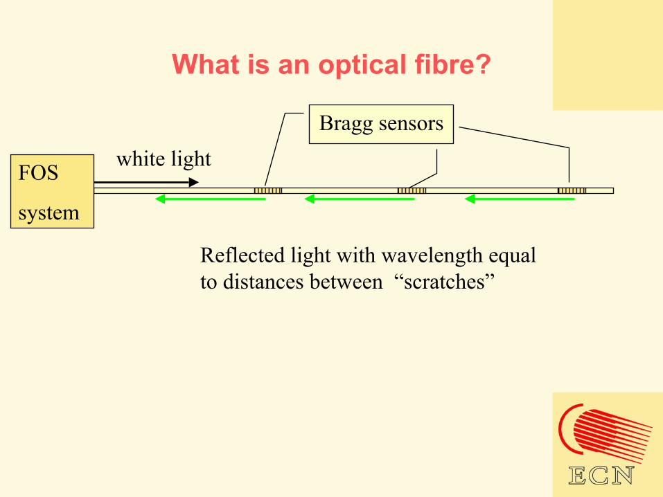
What is an optical fibre?
FOS
system
white lightBragg sensors
Reflected light with wavelength equal to distances between “scratches”
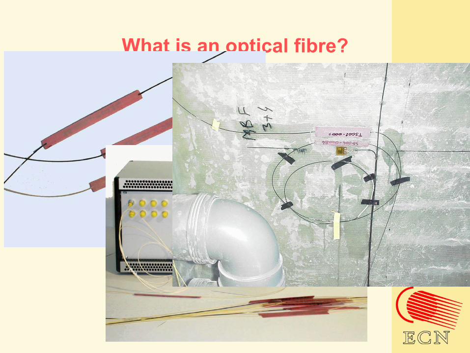
What is an optical fibre?

Contents of presentation
• Introduction to ECN• Introduction to condition monitoring• Possibilities of optical fibres• Test set-up• Experience with optical fibres• FOBM system layout
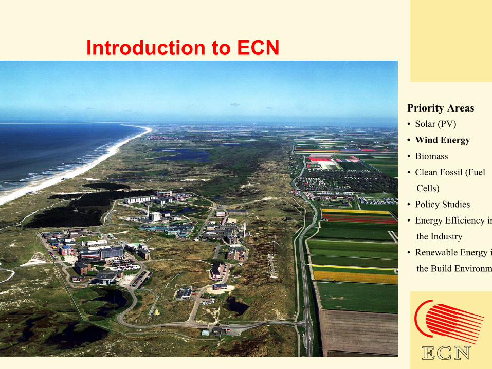
Introduction to ECN
Priority Areas • Solar (PV)
• Wind Energy
• Biomass
• Clean Fossil (Fuel
Cells)
• Policy Studies
• Energy Efficiency in
the Industry
• Renewable Energy in
the Build Environment
Introduction to ECN
Wind Energy
“With 45 employees the unit holds a strategic position between universities and industry covering all relevant wind energy disciplines; from trouble shooting to long term R&D, from training courses and design support to wind farm development and risk management.”
Four groups•Wind Farm Development•Wind Turbine Technology•Wind Farm Operation•Experiments
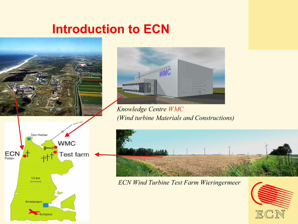
Introduction to ECN
Knowledge Centre WMC(Wind turbine Materials and Constructions)
ECN Wind Turbine Test Farm Wieringermeer
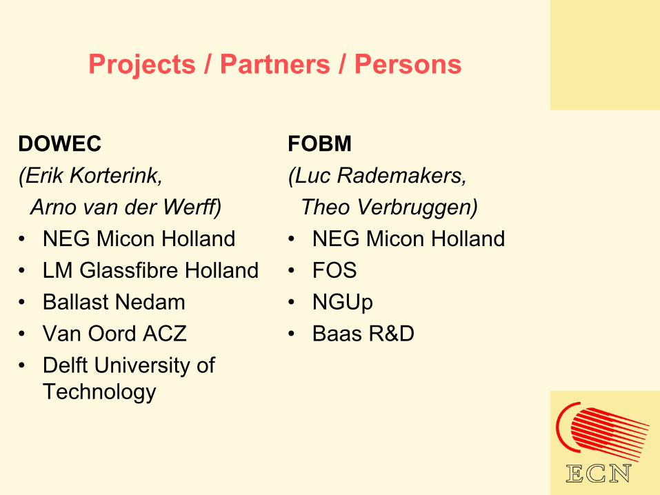
Projects / Partners / Persons
DOWEC(Erik Korterink, Arno van der Werff)
• NEG Micon Holland• LM Glassfibre Holland• Ballast Nedam• Van Oord ACZ• Delft University of
Technology
FOBM(Luc Rademakers, Theo Verbruggen)
• NEG Micon Holland• FOS• NGUp• Baas R&D
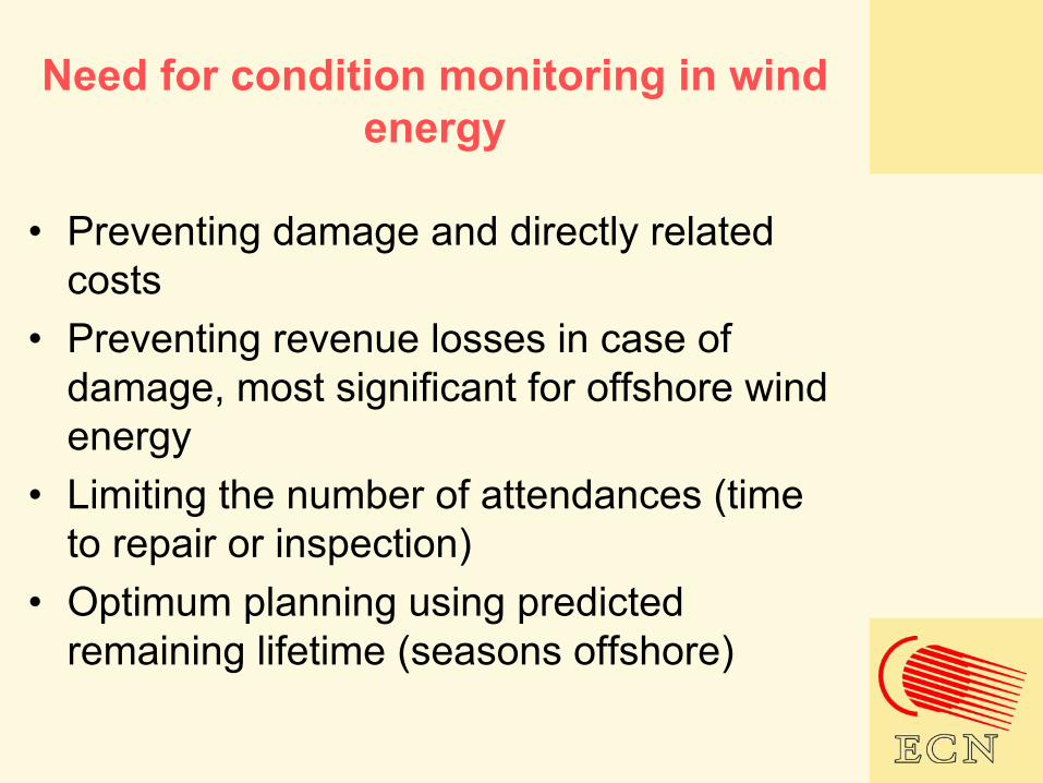
Need for condition monitoring in wind energy
• Preventing damage and directly related costs
• Preventing revenue losses in case of damage, most significant for offshore wind energy
• Limiting the number of attendances (time to repair or inspection)
• Optimum planning using predicted remaining lifetime (seasons offshore)
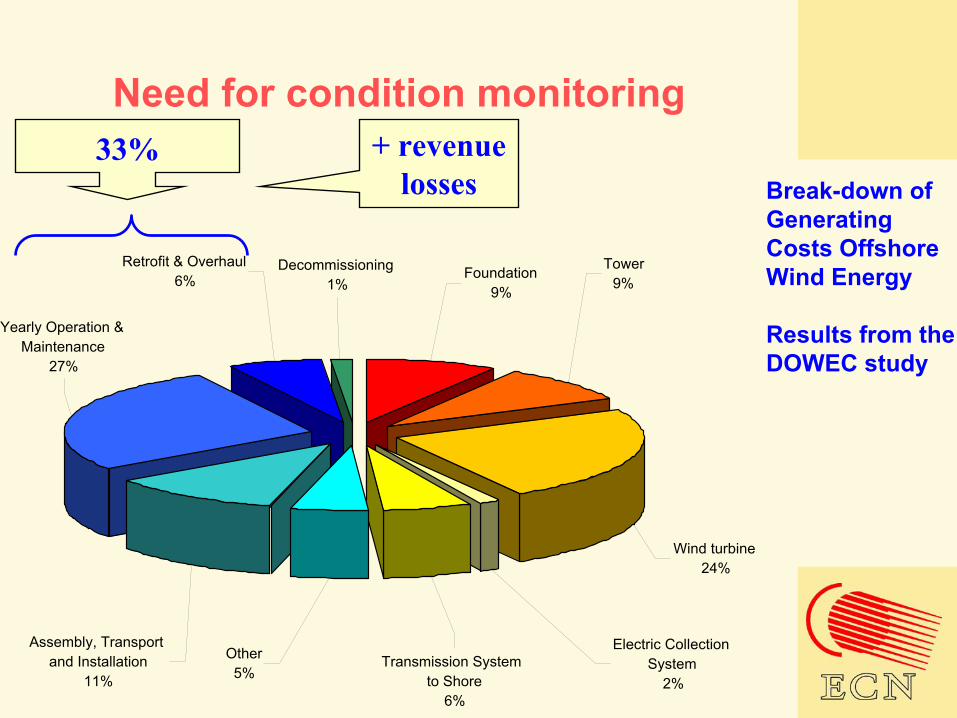
Need for condition monitoring
Break-down of Generating Costs Offshore Wind Energy
Results from the DOWEC study
Retrofit & Overhaul6%
Decommissioning1%
Wind turbine24%
Electric Collection System
2%
Other5%
Transmission System to Shore
6%
Foundation9%
Yearly Operation & Maintenance
27%
Assembly, Transport and Installation
11%
Tower9%
33% + revenue losses
Condition monitoring for wind turbines
Condition monitoring is a proven method inother branches. The application in wind energy differs from the present application:
• Stochastic loading versus stationary operation
• Preventing damage versus enlarging preventive maintenance period
• Trade-off between higher investment and lower damage costs
Condition monitoring for wind turbines
Condition monitoring is applicable to many wind turbine components:
• Blades• Drive train• Main bearing• Generator• General behaviour (degradation of power
curve)• Other…

Possibilities for optical fibres
All possible failure modes of the blades have been investigated on possibilities for condition monitoring systems
Some can be detected by a strain measurement; on basis of a changed strain distribution or a change in natural frequency or cumulative load spectrum

Possibilities for optical fibres
Trailing edge transverse cracks (source Allianz)
Trailing edge transverse cracks (details, source Allianz))
Possibilities for optical fibres
Supposed of a measuring strains with an optical fibre versus classical copper strain gauges:
• Non-conductive, important for lightning• More simple instrumentation• More reliable in time
Advantages to be demonstrated in 2 year R&D project

Possibilities for optical fibres
Topics of research:• Accuracy of measurement (zero drift,
temperature influence)• Reliability in time (opto-electronics,
sensors)
Next to field tests, laboratory experiments are planned in the WMC
DOWEC
Illustratieve resultaten, meetprogramma
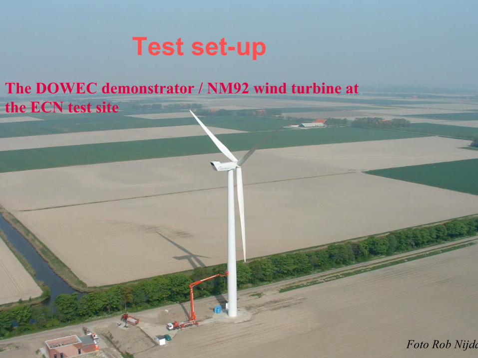
Foto Rob Nijdam
The DOWEC demonstrator / NM92 wind turbine at the ECN test site
Test set-up
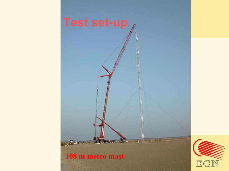
108 m meteo mast
Test set-up

Test set-upDistributed system:Distributed system:
•• frontfront--ends at different locations: sensor power ends at different locations: sensor power supply and all signal conditioning, EMC proofsupply and all signal conditioning, EMC proof
•• glass glass fiber fiber connectionsconnections
•• one central host pc: data collection and backone central host pc: data collection and back--up, transfer to ECN databaseup, transfer to ECN database
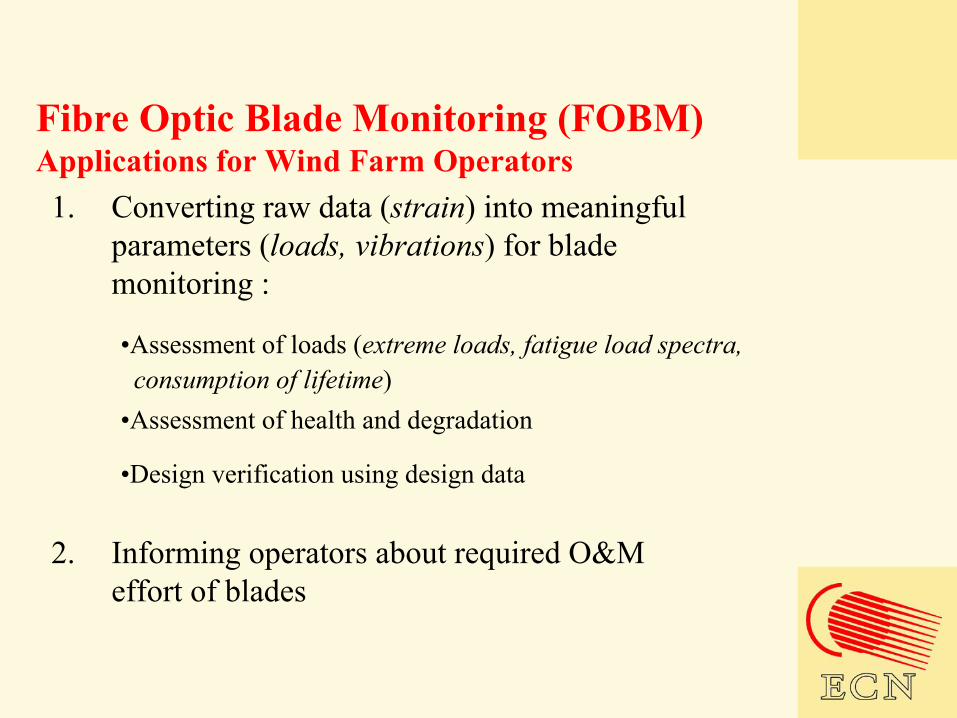
Fibre Optic Blade Monitoring (FOBM)Applications for Wind Farm Operators1. Converting raw data (strain) into meaningful
parameters (loads, vibrations) for blade monitoring :
•Assessment of loads (extreme loads, fatigue load spectra, consumption of lifetime)
•Assessment of health and degradation
•Design verification using design data
2. Informing operators about required O&M effort of blades

Example of time series
CLASSIC Flap [kNm] - OPTICAL Suction [kNm]OPTIC Compression [kNM]OPTICAL Flap[kNm]Azimuth angle

FOBM: Hardware
Optical fibres in blades
Data logger in hub
PC for control and alarm
Wind speed, Pitch angle Power
Strain,Loads,Spectra,…etc.

Wind farm PC for data storage and trending
FOBM: Network
Alarms
May 2003 10
FOSystem for reliable monitoringwith no drift, after unloading strain isback to initial position
Tensile-Tensile test (0.04% - 0.18%)Back to no strain after 0, 255 000, 438 000 & 500 000 cycles
N.B.: NO TEMPE RATURE COMPENSATION
-100-80-60-40-20
020406080
100
0 50 100 150 200 250
mic
rost
rain
Sensor #1
Sensor #2
STA RT A fter 255 00 0 Cy cles A fter 438 00 0 Cycles A fter 500 00 0 Cy cles255.000cycles
500.000cycles
time in arbitrary unitsmicrostrain
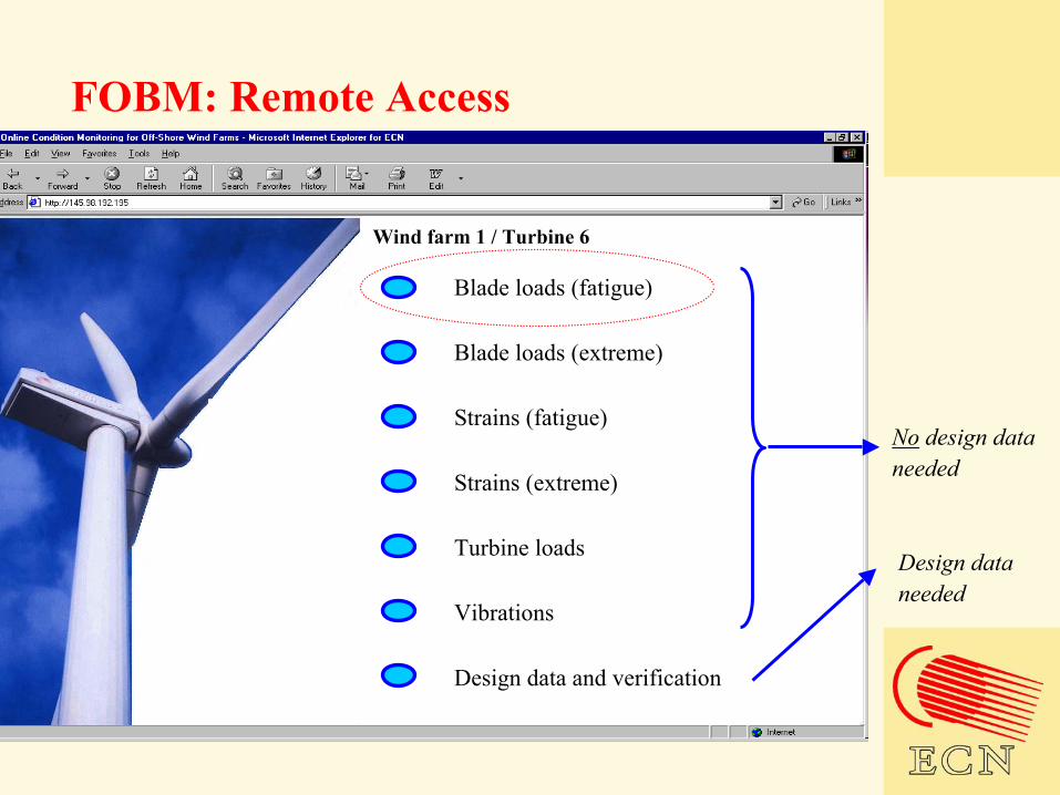
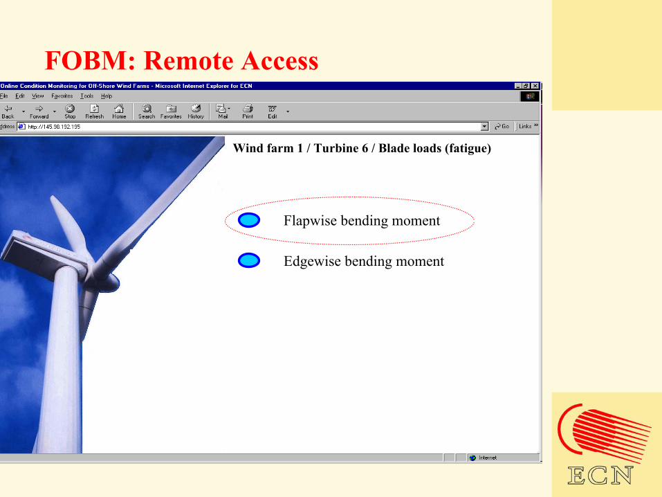
FOBM: Remote Access
Vibrations
Turbine loads
Design data and verification
Strains (fatigue)
Blade loads (fatigue)
Strains (extreme)
Blade loads (extreme)
Wind farm 1 / Turbine 6
No design data needed
Design data needed
May 2003 10
FOSystem for reliable monitoringwith no drift, after unloading strain isback to initial position
Tensile-Tensile test (0.04% - 0.18%)Back to no strain after 0, 255 000, 438 000 & 500 000 cycles
N.B.: NO TEMPE RATURE COMPENSATION
-100-80-60-40-20
020406080
100
0 50 100 150 200 250
mic
rost
rain
Sensor #1
Sensor #2
STA RT A fter 255 00 0 Cy cles A fter 438 00 0 Cycles A fter 500 00 0 Cy cles255.000cycles
500.000cycles
time in arbitrary unitsmicrostrain
FOBM: Remote Access
Edgewise bending moment
Flapwise bending moment
Wind farm 1 / Turbine 6 / Blade loads (fatigue)
May 2003 10
FOSystem for reliable monitoringwith no drift, after unloading strain isback to initial position
Tensile-Tensile test (0.04% - 0.18%)Back to no strain after 0, 255 000, 438 000 & 500 000 cycles
N.B.: NO TEMPE RATURE COMPENSATION
-100-80-60-40-20
020406080
100
0 50 100 150 200 250
mic
rost
rain
Sensor #1
Sensor #2
STA RT A fter 255 00 0 Cy cles A fter 438 00 0 Cycles A fter 500 00 0 Cy cles255.000cycles
500.000cycles
time in arbitrary unitsmicrostrain
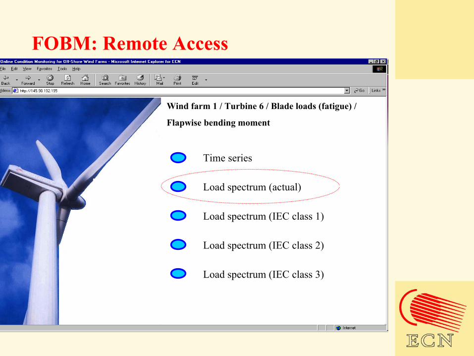
FOBM: Remote Access
Load spectrum (actual)
Time series
Wind farm 1 / Turbine 6 / Blade loads (fatigue) /
Flapwise bending moment
Load spectrum (IEC class 3)
Load spectrum (IEC class 2)
Load spectrum (IEC class 1)
May 2003 10
FOSystem for reliable monitoringwith no drift, after unloading strain isback to initial position
Tensile-Tensile test (0.04% - 0.18%)Back to no strain after 0, 255 000, 438 000 & 500 000 cycles
N.B.: NO TEMPE RATURE COMPENSATION
-100-80-60-40-20
020406080
100
0 50 100 150 200 250
mic
rost
rain
Sensor #1
Sensor #2
STA RT A fter 255 00 0 Cy cles A fter 438 00 0 Cycles A fter 500 00 0 Cy cles255.000cycles
500.000cycles
time in arbitrary unitsmicrostrain
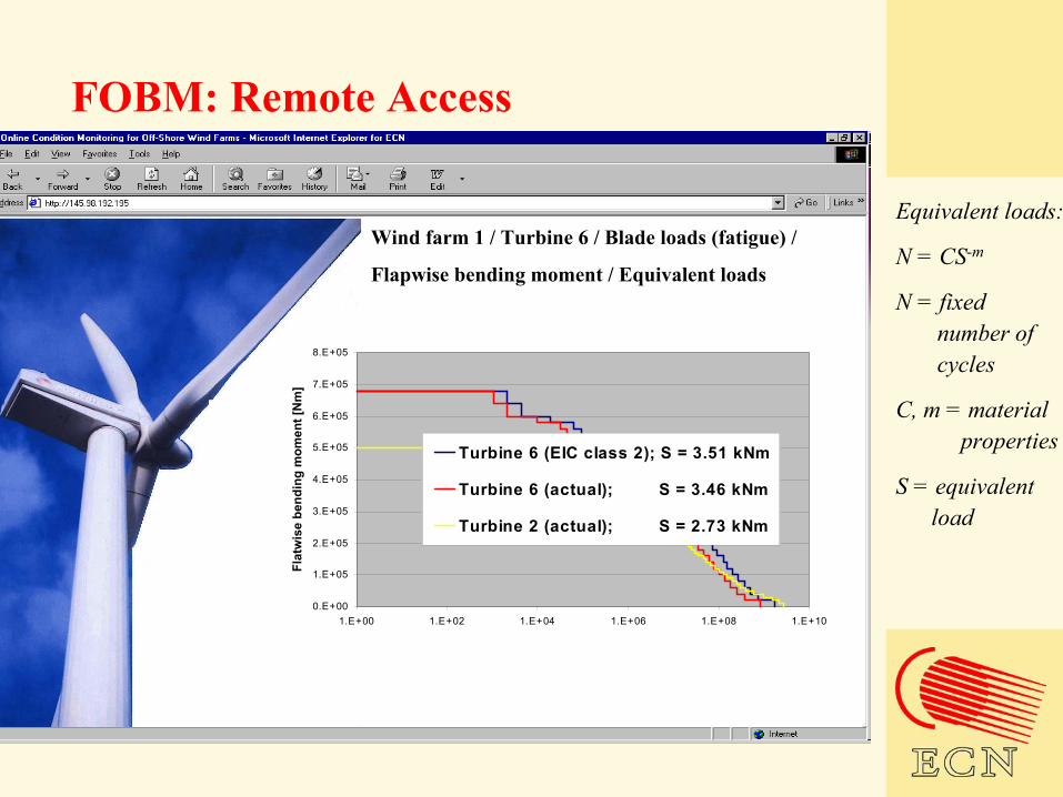
FOBM: Remote Access
Wind farm 1 / Turbine 6 / Blade loads (fatigue) /
Flapwise bending moment / Equivalent loads
Equivalent loads:
N = CS-m
N = fixed number of cycles
C, m = materialproperties
S = equivalentload
0.E+00
1.E+05
2.E+05
3.E+05
4.E+05
5.E+05
6.E+05
7.E+05
8.E+05
1.E+00 1.E+02 1.E+04 1.E+06 1.E+08 1.E+10
Flat
wis
e be
ndin
g m
omen
t [N
m]
Turbine 6 (EIC class 2); S = 3.51 kNm
Turbine 6 (actual); S = 3.46 kNm
Turbine 2 (actual); S = 2.73 kNm

May 2003 10
FOSystem for reliable monitoringwith no drift, after unloading strain isback to initial position
Tensile-Tensile test (0.04% - 0.18%)Back to no strain after 0, 255 000, 438 000 & 500 000 cycles
N.B.: NO TEMPE RATURE COMPENSATION
-100-80-60-40-20
020406080
100
0 50 100 150 200 250
mic
rost
rain
Sensor #1
Sensor #2
STA RT A fter 255 00 0 Cy cles A fter 438 00 0 Cycles A fter 500 00 0 Cy cles255.000cycles
500.000cycles
time in arbitrary unitsmicrostrain
FOBM: Remote Access
Vibrations
Turbine loads
Design data and verification
Strains (fatigue)
Blade loads (fatigue)
Strains (extreme)
Blade loads (extreme)
Wind farm 1 / Turbine 6
May 2003 10
FOSystem for reliable monitoringwith no drift, after unloading strain isback to initial position
Tensile-Tensile test (0.04% - 0.18%)Back to no strain after 0, 255 000, 438 000 & 500 000 cycles
N.B.: NO TEMPE RATURE COMPENSATION
-100-80-60-40-20
020406080
100
0 50 100 150 200 250
mic
rost
rain
Sensor #1
Sensor #2
STA RT A fter 255 00 0 Cy cles A fter 438 00 0 Cycles A fter 500 00 0 Cy cles255.000cycles
500.000cycles
time in arbitrary unitsmicrostrain
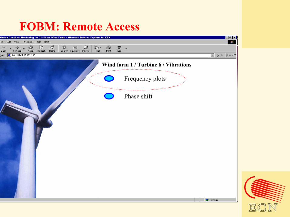
FOBM: Remote Access
Frequency plots
Phase shift
Wind farm 1 / Turbine 6 / Vibrations
May 2003 10
FOSystem for reliable monitoringwith no drift, after unloading strain isback to initial position
Tensile-Tensile test (0.04% - 0.18%)Back to no strain after 0, 255 000, 438 000 & 500 000 cycles
N.B.: NO TEMPE RATURE COMPENSATION
-100-80-60-40-20
020406080
100
0 50 100 150 200 250
mic
rost
rain
Sensor #1
Sensor #2
STA RT A fter 255 00 0 Cy cles A fter 438 00 0 Cycles A fter 500 00 0 Cy cles255.000cycles
500.000cycles
time in arbitrary unitsmicrostrain
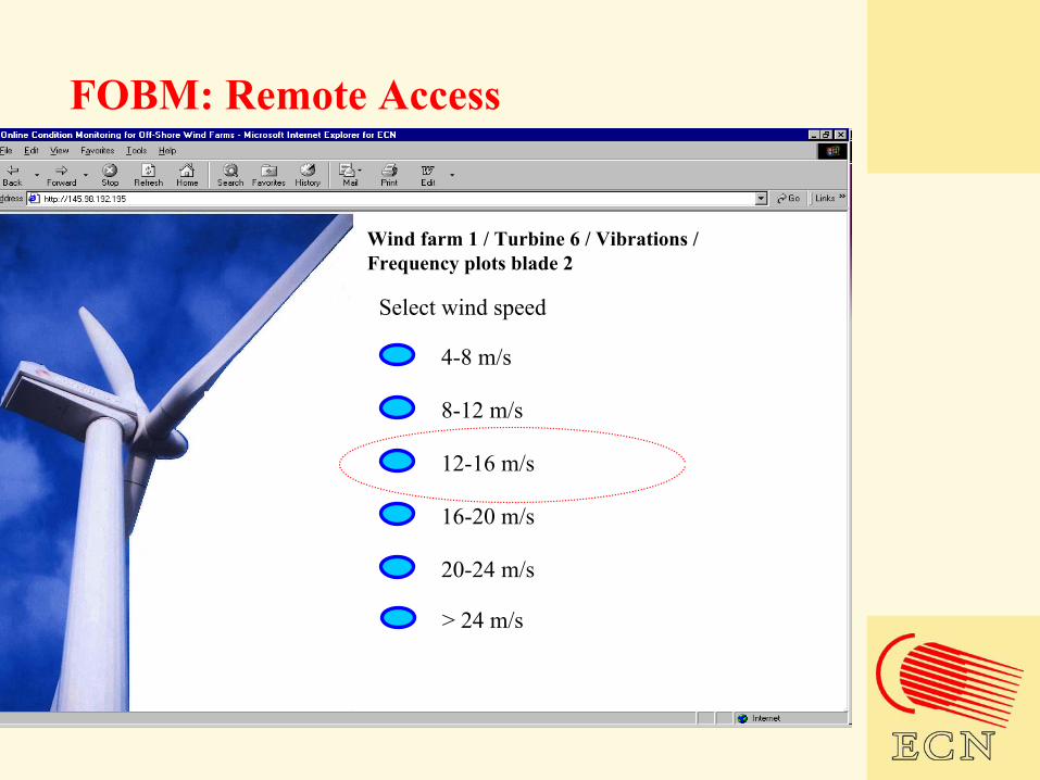
FOBM: Remote Access
Select wind speed
Wind farm 1 / Turbine 6 / Vibrations / Frequency plots blade 2
4-8 m/s
8-12 m/s
12-16 m/s
16-20 m/s
20-24 m/s
> 24 m/s
May 2003 10
FOSystem for reliable monitoringwith no drift, after unloading strain isback to initial position
Tensile-Tensile test (0.04% - 0.18%)Back to no strain after 0, 255 000, 438 000 & 500 000 cycles
N.B.: NO TEMPE RATURE COMPENSATION
-100-80-60-40-20
020406080
100
0 50 100 150 200 250
mic
rost
rain
Sensor #1
Sensor #2
STA RT A fter 255 00 0 Cy cles A fter 438 00 0 Cycles A fter 500 00 0 Cy cles255.000cycles
500.000cycles
time in arbitrary unitsmicrostrain
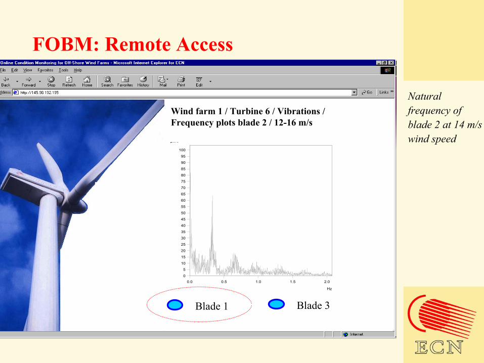
FOBM: Remote Access
Wind farm 1 / Turbine 6 / Vibrations / Frequency plots blade 2 / 12-16 m/s
0
5
10
15
20
25
30
35
40
45
50
55
60
65
70
75
80
85
90
95
100
µV/V
0.0 0.5 1.0 1.5 2.0
Hz
Blade 1 Blade 3
Natural frequency of blade 2 at 14 m/s wind speed

May 2003 10
FOSystem for reliable monitoringwith no drift, after unloading strain isback to initial position
Tensile-Tensile test (0.04% - 0.18%)Back to no strain after 0, 255 000, 438 000 & 500 000 cycles
N.B.: NO TEMPE RATURE COMPENSATION
-100-80-60-40-20
020406080
100
0 50 100 150 200 250
mic
rost
rain
Sensor #1
Sensor #2
STA RT A fter 255 00 0 Cy cles A fter 438 00 0 Cycles A fter 500 00 0 Cy cles255.000cycles
500.000cycles
time in arbitrary unitsmicrostrain
FOBM: Remote Access
Wind farm 1 / Turbine 6 / Vibrations / Frequency plots blade 1 and 2 / 12-16 m/s
0
5
10
15
20
25
30
35
40
45
50
55
60
65
70
75
80
85
90
95
100
µV/V
0.0 0.5 1.0 1.5 2.0
Hz
Blade 3
Natural frequency of blade 2 and blade 1 at 14 m/s wind speed
Blade 1

Any questions?