application of the electrothermal average inductor model for analyses of boost converters krzysztof...
TRANSCRIPT

Application of the Electrothermal Average Inductor Model for Analyses of Boost Converters
Krzysztof Górecki, Janusz Zarębski, Kalina Detka
Gdynia Maritime UniversityDepartment of Marine Electronics

Outline Introduction The average electrothermal model
of the diode-transistor switch The average electrothermal model
of the inductor Results of calculations and
measurements Conclusions

Introduction (1) The boost converter is frequently used in switched-mode
power supplies. The important parts of this converter are semiconductor
devices and an inductor with the ferromagnetic core. In literature the properties of this circuit are analyzed, but
the consideration focused only on semiconductor devices ignoring properties of magnetic elements.
In previous authors papers it is shown, that the nonlinearity dependence L(i) significantly influences the course of characteristics of the considered converter.
In the cited papers, in order to calculate the characteristics of dc-dc converters the classical transient analysis method is used.
The analysis is time consuming, and there are often problems to obtain convergence of computations.
During dc-dc converters operation the internal components temperature rises due to a self-heating phenomenon.
Introduction (2) To take into account this phenomenon in the computer
analysis, special electrothermal models are required. The average electrothermal model of the diode –
transistor switch for SPICE is proposed, but in this model non-linearity of the inductor characteristics and self-heating in this element are omitted.
In this paper the average electrothermal model of the inductor dedicated to the electrothermal analysis of dc-dc converters is proposed.
This model takes into account magnetic and thermal phenomena in the inductor and power losses in the core and in the winding.
The model is used to calculate non-isothermal characteristics of the boost converter.

The average electrothermal model of the diode-transistor switch
Control voltage sources Et and Er represent the unipolar transistor, connected to terminals 1, 2 and 5
The diode (between the terminals 3 and 4) is represented by the controlled current source Gd.
The auxiliary circuit is used to determine the mode of dc – dc converter (CCM or DCM) including the considered switch.
The aided block model the temperature changes of transistor resistance RON, series diode resistance RD and voltage UD on the forward biased p-n junction.
The internal diode and transistor temperature are calculated in the thermal model.
The average electrothermal model of the inductor
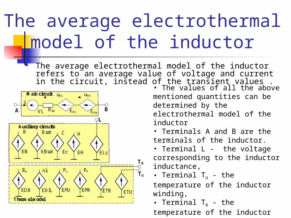
The average electrothermal model of the inductor refers to an average value of voltage and current in the circuit, instead of the transient values .
• The values of all the above mentioned quantities can be determined by the electrothermal model of the inductor• Terminals A and B are the terminals of the inductor.• Terminal L - the voltage corresponding to the inductor inductance, • Terminal TU - the temperature of the inductor winding, • Terminal TR - the temperature of the inductor core.

The average electrothermal model of the inductor (2) In the main circuit:
the voltage source VL with zero output voltage monitors the current of the inductor,
the resistor RS0 represents the winding resistance of the inductor for the direct current at the reference temperature T0
the controlled voltage source ERS describes the influence of temperature and losses of the inductor series resistance.
the controlled voltage source ERN models the skin effect phenomenon
In the auxiliary block the controlled voltage sources are used to calculate the value of: the magnetic force H, flux density B, Bsat saturation flux density the auxiliary value C.
The thermal model allows calculating an excess of the core TR and winding TU temperature above the ambient temperature Ta.

Results of calculations and measurements
The average electrothermal model of the inductor is used to calculate the characteristics of the boost converter,
the inductor L containing 27 turns of enamel copper wire of the diameter of 0.8 mm wound on a toroidal ferrite core RTF25x15x10 made of F867 material.
The considered circuit is excited by the DC voltage equal to 12 V, the frequency of the control signal is f = 50 kHz.
Results of calculations and measurements (2)
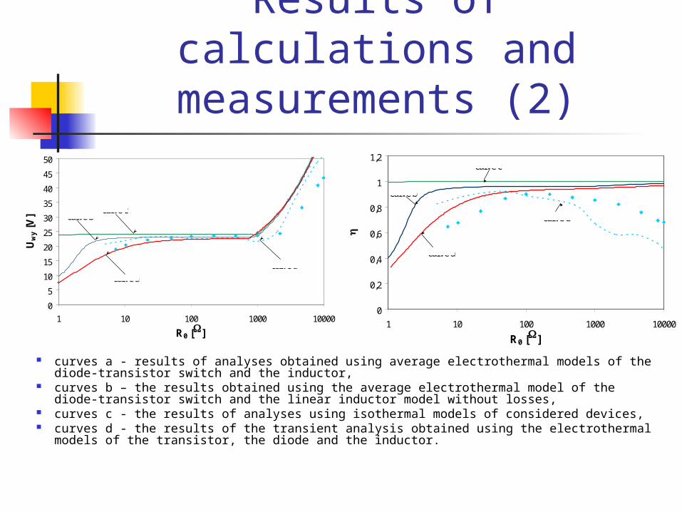
curves a - results of analyses obtained using average electrothermal models of the diode-transistor switch and the inductor,
curves b – the results obtained using the average electrothermal model of the diode-transistor switch and the linear inductor model without losses,
curves c - the results of analyses using isothermal models of considered devices, curves d - the results of the transient analysis obtained using the electrothermal models
of the transistor, the diode and the inductor.
0
5
10
15
20
25
30
35
40
45
50
1 10 100 1000 10000
R0 [W]
Uw
y [V
]
d = 0.5
RTF
curve a
curve bcurve c
curve d
0
0,2
0,4
0,6
0,8
1
1,2
1 10 100 1000 10000
R0 [W]h
d = 0.5f = 50 kHz RTF
curve a
curve b
curve c
curve d
Results of calculations and measurements (3)
It is easy to notice that in the considered range of load resistance the boost converter operates in both CCM and DCM modes.
Taking into account non-linearity of L(i) caused the shifts of the boundary between CCM and DCM mode towards bigger values of load resistance R0.
In the range of small values of R0 it can be seen that using the classical model without losses allows obtaining the constant output voltage Uwy and watt-hour efficiency.
From both the considered models the increasing dependences Uwy(R0) and h(R0) are obtained,
Taking into account non-linearity of the inductor model reduces the converter output voltage and watt-hour efficiency.
It is worth noticing, that taking into account the inductor non-linearities and losses in the inductor causes the reduction of 50% in the output voltage, and the watt-hour efficiency - as much as 60%.

Results of calculations and measurements (4)
The considered dependences are decreasing functions.
For the high resistance R0, the core temperature is higher than the winding temperature and for the small resistance R0 the winding temperature achieves the higher value.
The computations time for the presented characteristics using average electrothermal models was about a ten miliseconds, whereas the determination of these characteristics by the transient electrothermal model takes several hours.
0
20
40
60
80
100
120
140
1 10 100 1000 10000
R0 [W]
TU, T
R [
o C]
d = 0.5
TU
TR
f = 50 kHz
RTF

Conclusions The paper presents the average electrothermal model of
the inductor dedicated to determine non-isothermal characteristics of dc-dc converters using SPICE.
The proposed model takes into account the dependence of inductance and series resistance on: the inductor current, frequency, temperature inductor construction parameters parameters of the core.
The results of computations show that taking into account in the presented model the physical phenomenon clearly affect characteristics of the considered circuit
In particular, the shift of the boundary between CCM and DCM mode towards higher values of R0 resistance is observed.
Conclusions (2) The output voltage and watt-hour efficiency of
the boost converter in the range of small values of R0 decrease.
The modified model also allows the computation of the core and winding temperature.
Simultaneously, the time needed to compute the non-isothermal characteristics of the considered converter is much shorter than using the classical transient analysis and the electrothermal model of the inductor.