application of the observational method for · pdf fileobservational method for railway...
TRANSCRIPT

APPLICATION OF THE OBSERVATIONAL METHOD FOR RAILWAY EARTHWORK STABILISATION IN THE UK
Sangmin Lee, Senior Geotechnical Engineer

INTRODUCTION
• Fundamentals of the Observational Method
• Application of the Observational Method for Railway Earthwork
Stabilisation in the UK: South of Manningtree Railway Embankment
- Project Background
- Base Design
- Contingency Design
- Monitoring Plan & Trigger Levels
2

FUNDAMENTALS OF THE OBSERVATIONAL METHOD
3

Brief History
Quoted from Soil Mechanics in Engineering Practice, Terzaghi, 1945:
In the past, only two methods have been used for coping with the inevitable
uncertainties:
either to adopt an excessive factor of safety, or else to make assumptions in
accordance with general, average experience…..The first method is wasteful; the
second is dangerous.
Soil mechanics, as we understand it today, provides a third method which could be
called the experimental method.
FUNDAMENTALS OF THE OBSERVATIONAL METHOD
4

FUNDAMENTALS OF THE OBSERVATIONAL METHOD
Brief History
Peck’s Rankine Lecture (1969):
•An integrated process for predicting, monitoring, reviewing and modifying
designs without compromising safety
•To successfully implement OM, it was necessary to have two designs
compared with the traditional single design approach in Geotechnics:
a design starting with the most probable (best estimate) condition
and varying the design and/or construction to the planned most
unfavourable condition, should observed behaviour be worst than
those predicted based on best estimate conditions.
Powderham’s Approach – Progressive modification
5

FUNDAMENTALS OF THE OBSERVATIONAL METHOD
Guidances and Standards available in the UK
• CIRIA (Construction Industry Research and Information Association in the
UK): 1999. CIRIA Report 185 “The Observational Method in Ground
Engineering: principles and applications”
• Network Rail: 2009. Guidance Note (NR/GN/CIV/801) “The application of
the Observational Approach to the design of remedial works to
earthworks”
• Eurocode: EN 1997-1: Section 2: Basis of geotechnical design
6

APPLICATION OF THE OBSERVATIONAL METHOD FOR RAILWAY EARTHWORK STABILISATION IN THE UK
• Project Background
• Base Design
• Contingency Design
• Monitoring Plan & Trigger Levels
7

PROJECT BACKGROUND
Location
8
PROJECT BACKGROUND
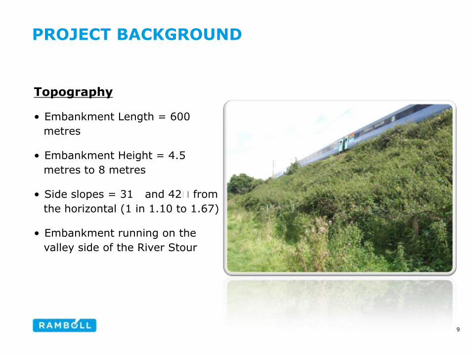
Topography
• Embankment Length = 600
metres
• Embankment Height = 4.5
metres to 8 metres
• Side slopes = 31 and 42 from
the horizontal (1 in 1.10 to 1.67)
• Embankment running on the
valley side of the River Stour
9
PROJECT BACKGROUND
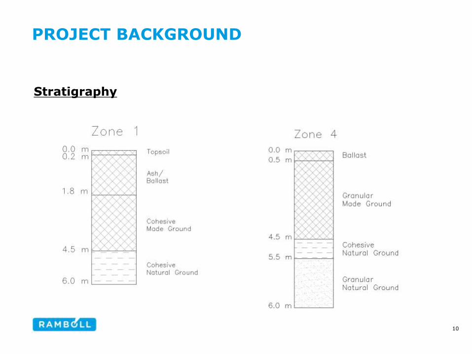
Stratigraphy
10
PROJECT BACKGROUND
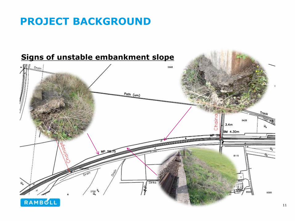
Signs of unstable embankment slope
11
PROJECT BACKGROUND
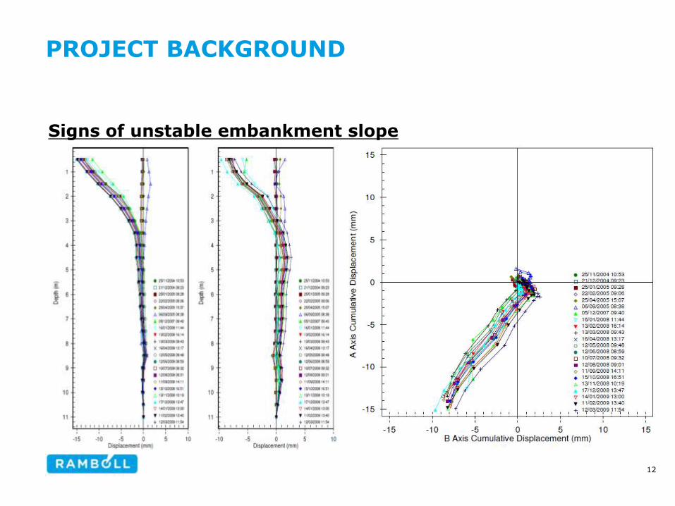
Signs of unstable embankment slope
12
PROJECT BACKGROUND
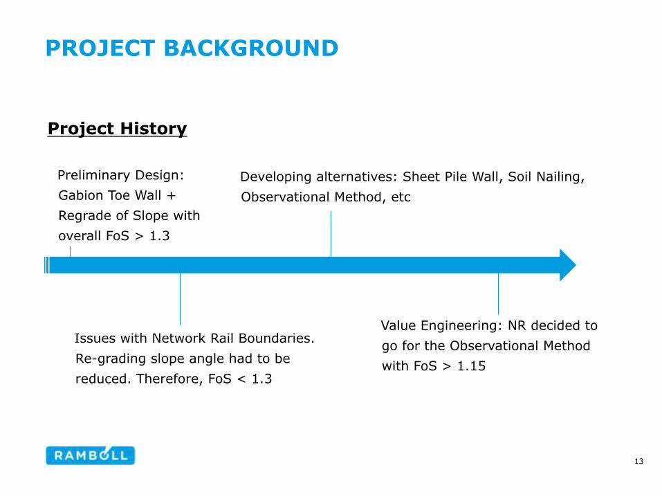
Project History
Preliminary Design:
Gabion Toe Wall +
Regrade of Slope with
overall FoS > 1.3
Issues with Network Rail Boundaries.
Re-grading slope angle had to be
reduced. Therefore, FoS < 1.3
Developing alternatives: Sheet Pile Wall, Soil Nailing,
Observational Method, etc
Value Engineering: NR decided to
go for the Observational Method
with FoS > 1.15
13
WHAT TO DO WITH THE OM?
• Base Design
• Contingency Design
• Monitoring Plan
- Intervention Plan, Trigger Levels, Monitoring Frequency
14

DESIGN REQUIREMENTS
• Design in accordance with Network Rail Guidance Note (NR/GN/CIV/801)
and CIRIA Report 185
• Overall Factor of Safety and Soil Conditions
• Settlement limit for remediated embankments
Base Design Contingency Design
Overall Factor of Safety
FoS > 1.15 FoS > 1.3
Conditions Most Probable Most Unfavourable
Time after re-opening the track to traffic
Maximum permitted cumulative settlement (track)
4 weeks 15 mm
6 months 25 mm
12 months 30 mm
15
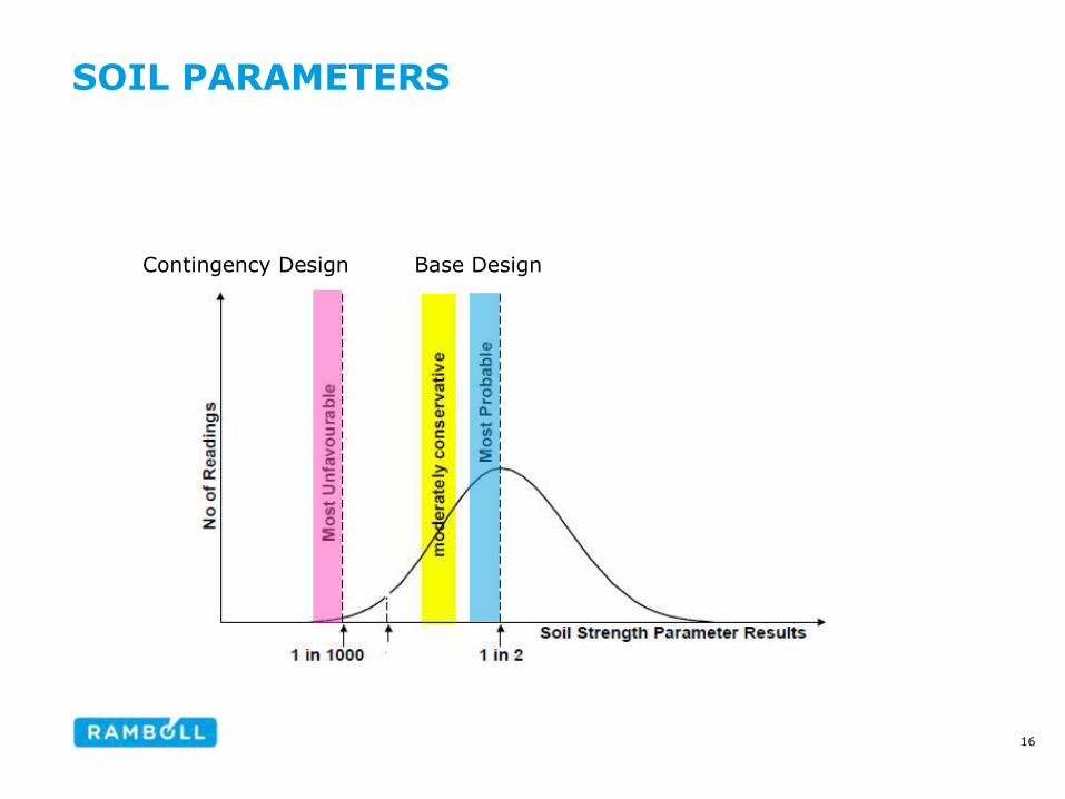
SOIL PARAMETERS
Base Design Contingency Design
16
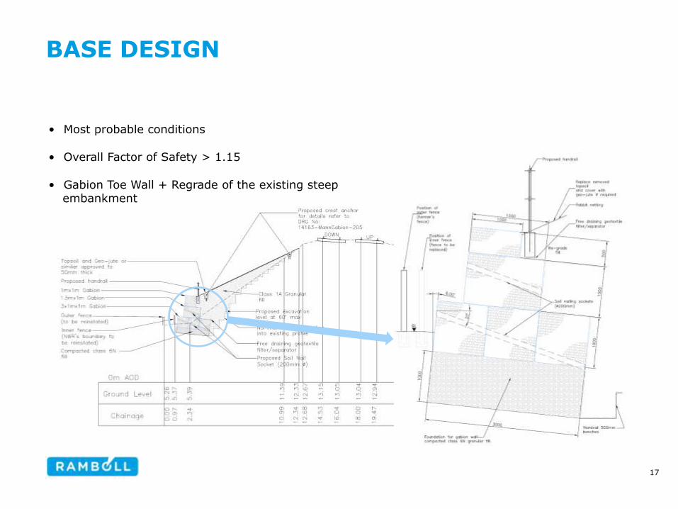
BASE DESIGN
• Most probable conditions
• Overall Factor of Safety > 1.15
• Gabion Toe Wall + Regrade of the existing steep embankment
17
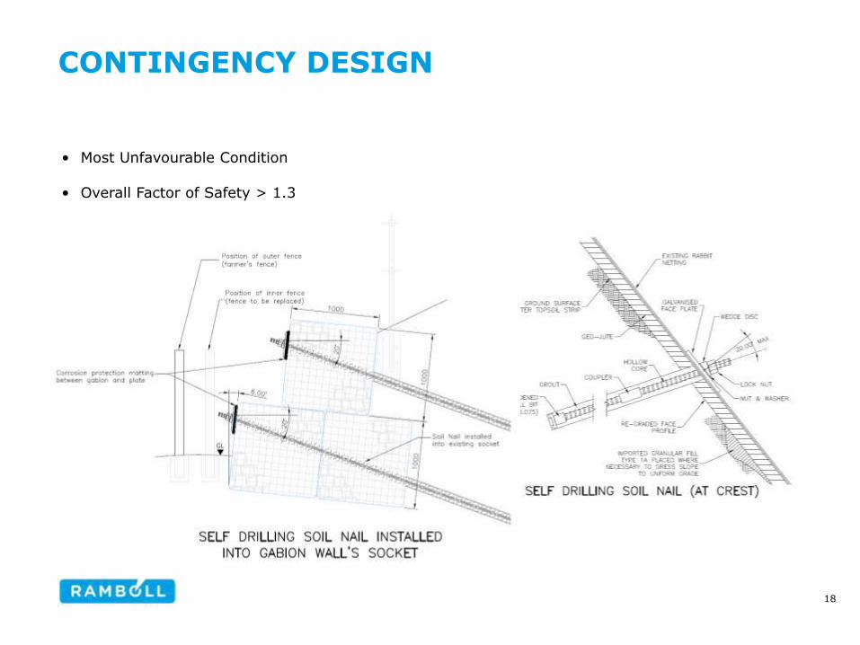
CONTINGENCY DESIGN
• Most Unfavourable Condition
• Overall Factor of Safety > 1.3
18
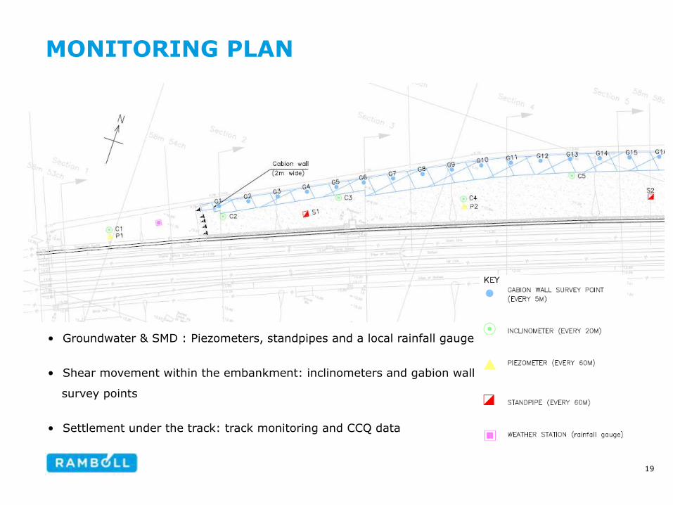
MONITORING PLAN
• Groundwater & SMD : Piezometers, standpipes and a local rainfall gauge
• Shear movement within the embankment: inclinometers and gabion wall
survey points
• Settlement under the track: track monitoring and CCQ data
19
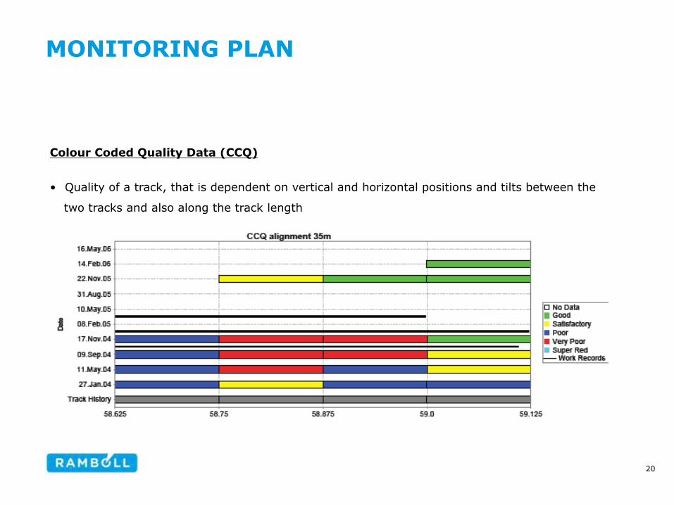
MONITORING PLAN
Colour Coded Quality Data (CCQ)
• Quality of a track, that is dependent on vertical and horizontal positions and tilts between the
two tracks and also along the track length
20

MONITORING PLAN
Intervention level (trigger value): a pre-determined point at which a decision is
made about a change to the design, construction programme or detail(s) of the site
works.
• Action level (RED value) -
The point at which a planned
modification is implemented
• Warning level (AMBER
value) - The point at which
an intervention plan is
implemented.
Traffic light system for an incremental excavation process (CIRIA 185, 1999)
21
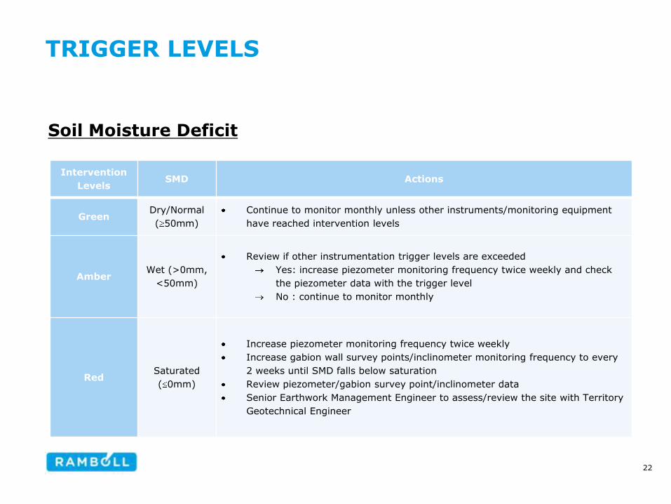
TRIGGER LEVELS
Soil Moisture Deficit
Intervention
Levels SMD Actions
Green Dry/Normal
( 50mm)
Continue to monitor monthly unless other instruments/monitoring equipment
have reached intervention levels
Amber Wet (>0mm,
<50mm)
Review if other instrumentation trigger levels are exceeded
Yes: increase piezometer monitoring frequency twice weekly and check
the piezometer data with the trigger level
No : continue to monitor monthly
Red Saturated
( 0mm)
Increase piezometer monitoring frequency twice weekly
Increase gabion wall survey points/inclinometer monitoring frequency to every
2 weeks until SMD falls below saturation
Review piezometer/gabion survey point/inclinometer data
Senior Earthwork Management Engineer to assess/review the site with Territory
Geotechnical Engineer
22
TRIGGER LEVELS
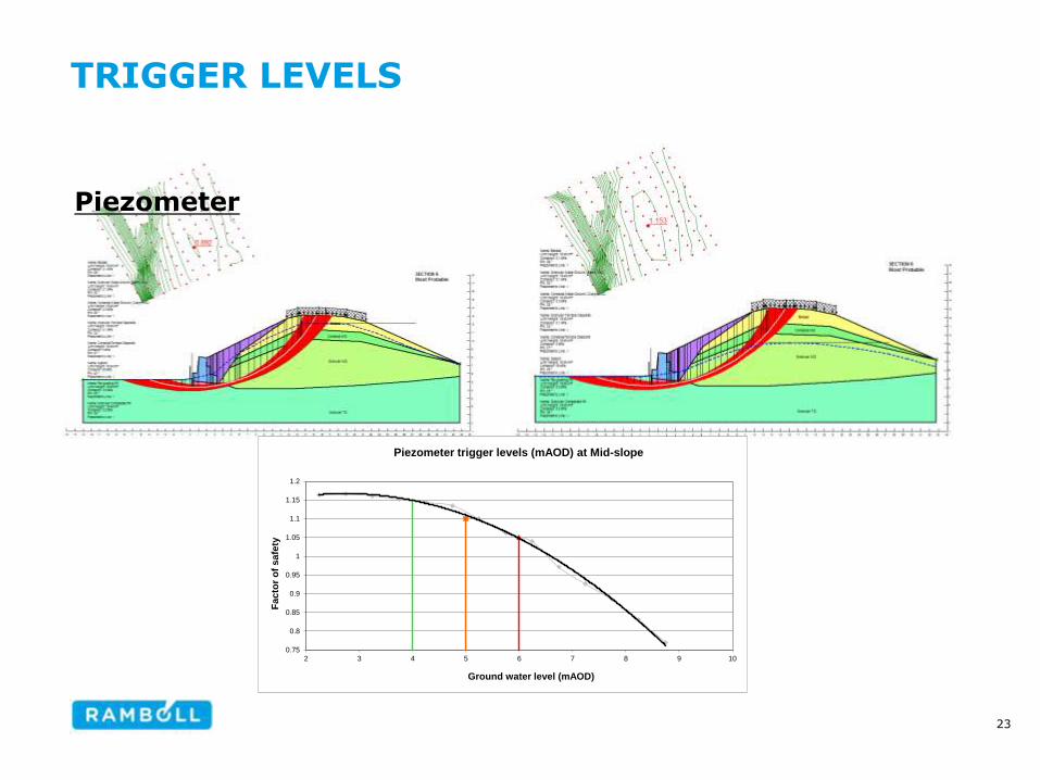
Piezometer
0.75
0.8
0.85
0.9
0.95
1
1.05
1.1
1.15
1.2
2 3 4 5 6 7 8 9 10
Fac
tor
of
sa
fety
Ground water level (mAOD)
Piezometer trigger levels (mAOD) at Mid-slope
23

TRIGGER LEVELS
Piezometer
Intervention Levels
Piezometer
/standpipe
(h, mAOD)
Actions
Green zone various for each
instrument
Continue to monitor monthly unless other instruments/monitoring
equipment have reached intervention levels
Amber zone various for each
instrument
Continue to monitor twice weekly until SMD falls below saturation
and/or the intervention level goes down to Green
Consider to increase frequency of gabion wall survey points and
inclinometers
Red zone various for each
instrument
Continue to monitor twice weekly
Increase monitoring frequency of gabion wall survey points and
inclinometers to at least every 2 weeks
Review inclinometer and gabion wall data
Senior Earthwork Management Engineer to assess/review the site
with Territory Geotechnical Engineer
24
TRIGGER LEVELS
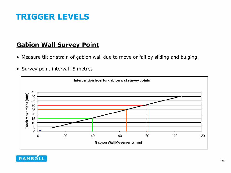
Gabion Wall Survey Point
• Measure tilt or strain of gabion wall due to move or fail by sliding and bulging.
• Survey point interval: 5 metres
0
5
10
15
20
25
30
35
40
45
0 20 40 60 80 100 120
Tra
ck M
ovem
en
t (m
m)
Gabion Wall Movement (mm)
Intervention level for gabion wall survey points
25

TRIGGER LEVELS
Gabion Wall Survey Point
26

TRIGGER LEVELS
Gabion Wall Survey Point
Intervention
Levels
Gabion wall
displacement
(d, mm)
Actions
Green zone d <40 Continue to monitor monthly unless other instruments/monitoring equipment
have reached intervention levels
Amber zone 40 d <65
Review CCQ data, inclinometer data alongside gabion data
Increase monitoring frequency of gabion wall survey points to every 2 weeks
Network Rail representative to undertake site visit
Senior Earthwork Management Engineer to assess/review the site with Territory
Geotechnical Engineer
Decision on further action (if any) to be documented on file
Red zone 65 d <80
Increase monitoring frequency of both gabions and inclinometer to at least every
2 weeks until movement slows or is agreed with Territory Geotechnical Engineer
Senior Earthwork Management Engineer to discuss site with Track Section
Manager
Network Rail personnel to undertake site visit ASAP
Advise mainframe contractor of site mobilisation possibility
Give strong consideration to undertaking soil nail installation in problematic areas
Decision on further action (if any) to be documented on file
27
TRIGGER LEVELS
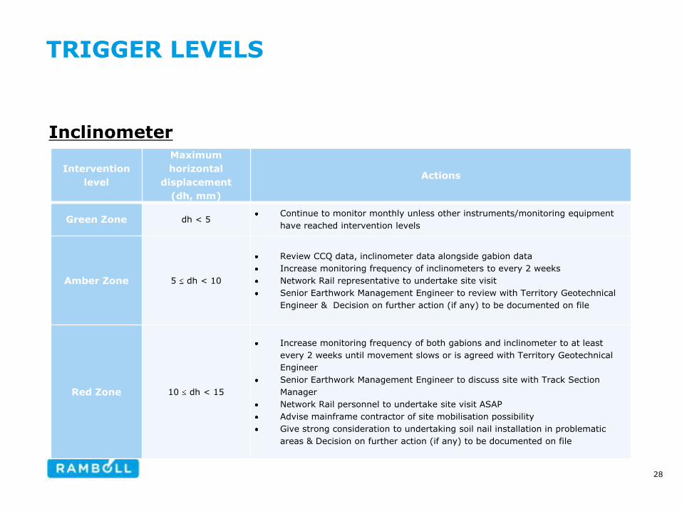
Inclinometer
Intervention
level
Maximum
horizontal
displacement
(dh, mm)
Actions
Green Zone dh < 5 Continue to monitor monthly unless other instruments/monitoring equipment
have reached intervention levels
Amber Zone 5 dh < 10
Review CCQ data, inclinometer data alongside gabion data
Increase monitoring frequency of inclinometers to every 2 weeks
Network Rail representative to undertake site visit
Senior Earthwork Management Engineer to review with Territory Geotechnical
Engineer & Decision on further action (if any) to be documented on file
Red Zone 10 dh < 15
Increase monitoring frequency of both gabions and inclinometer to at least
every 2 weeks until movement slows or is agreed with Territory Geotechnical
Engineer
Senior Earthwork Management Engineer to discuss site with Track Section
Manager
Network Rail personnel to undertake site visit ASAP
Advise mainframe contractor of site mobilisation possibility
Give strong consideration to undertaking soil nail installation in problematic
areas & Decision on further action (if any) to be documented on file
28

POST CONSTRUCTION MONITORING PROCESS MAP
Inclinometer
Post Construction Monitoring Process / scheme for 2 years – to
be reviewed every year
Gabion Wall Track Piezometers / Standpipes SMD (Soil Moisture Deficit)
Monitoring undertaken every month (12No spaced 20m apart altering in toe and midslope).
Monitoring of Gabion wall undertaken every month. Absolute total position (XYZ) to be recorded
Monitoring to be undertaken and reviewed by NR during construction by a track engineer only in accordance with NR/SP/CIV/071 and NR/BS/LI/045 (issue 2). Information (CCQ data, etc) to be made available for the DE, SEME etc.
Monitor Piezometers monthly. 8 Piezometers monitored with a data logger and 4 monitored manually (Intervention levels to be obtained from slope stability analysis at location of Piezometer).
Soil Moisture Deficit to be remotely monitored on a weekly basis using site rainfall data.
Green dh<5
Amber
5 dh<10
Red
10 dh<15
Green d<40
Amber
40 d<65
Red
65 d<80
Green Amber Red Green Amber Red Green <50
Amber >0, <50
Red ≤0
Green
Continue to monitor at existing frequency unless other instruments/ monitoring equipment have reached amber or red intervention levels
Consider the Following:
What does the monitoring data of the instruments show?
Is there an anomalous reading?
Is a site visit needed by DE, CM and NRR?
Do we need to assess / interpret all data (including site visit data)?
Is a decision meeting needed / N.R to review?
Does the SEME need to review the above with TGE?
What actions need to be taken? All considerations need to be documented on file
Amber
Red
Consider the following:
What does the monitoring data of the instruments show?
Is there an anomalous reading?
Is a Site visit needed by DE, CM, NRR?
Does the SEME need to asses / review the site with Track Section Manager?
Does there need to be a Decision meeting / N.R to Review?
What actions need to be taken? All considerations need to be documented on file
UNDERTAKING REACTIVE SOIL NAILLING IF:
TME has problems with top/alignment levels over the effected area attributed to the embankment, or
Features of earthwork instability apparent (i.e. drop in cess), or
Movement continues by a further 10mm for Inclinometers and 50mm for Gabion wall survey points beyond the red threshold level after the initial triggering reading, or
It is considered necessary by TGE
What to do at each intervention level (Green, Amber, and Red) Key DE – Design Engineer CM – Construction Manager NRR – Network Rail Representative SEME – Senior Earthwork Management Engineer TGE – Territory Geotechnical Engineer TME – Track maintenance Engineer dh – Maximum horizontal displacement d – Displacement
Actions:
Do Nothing
Amend Trigger Levels
Increase monitoring frequency
Proceed to Red Trigger level All actions need to be documented on file
Actions:
Do Nothing
Amend Trigger Levels
Increase monitoring frequency
Advise mainframe contractor of site mobilisation possibility
Activate soil Nailing All actions need to be documented on file
29
CONCLUSIONS
• 1st time used in Network Rail East Anglia Territory
• Network Rail saved £1million
• Trigger values stay in Green, and Intervention Plan/ Planned Modification
not implemented up to date.
• Base Design: Overall FoS > 1.15 with Most Probable conditions
• Contingency design: Overall FoS > 1.3 with Most Unfavourable Conditions
• Monitoring System: a weather station including a rainfall gauge,
piezometers, inclinometers, gabion wall survey points, and CCQ Data
30
THANK YOU
31