applications and benefits - abb
TRANSCRIPT

X JORNADAS TÉCNICAS - ABB EN CHILE, 11-12 ABRIL, 2017
HVDC – SystemsApplications and Benefits
Felipe Nobre, Gerente de Subestaciones, Chile
ABB y la Innovación
Porque HVDC
Tecnología HVDC
Experiencia en el Proyecto Rio Madeira, HVDC ± 600 kV
April 18, 2017 Slide 2
Agenda

Moldando el mundo hoy por medio da la innovaciónPionera en tecnología desde 1883
Os fundadores
1900
Robôs industriais
Turbochargers
HVDC
Ultra-alta tensão
Painéis isoladosa gás
Acionamentos einversores de frequência
Turbina a vapor
1920 1930 1940
1990 2000
19601970
Sistema deacionamentoelétrico paralocomotivas
1950
Motor sem redutor
1980
Sistemas depropulsão elétrica
Sistemas decontrole distribuído
Turbinaa gás
April 18, 2017 Slide 3
Slid
e4
(22)
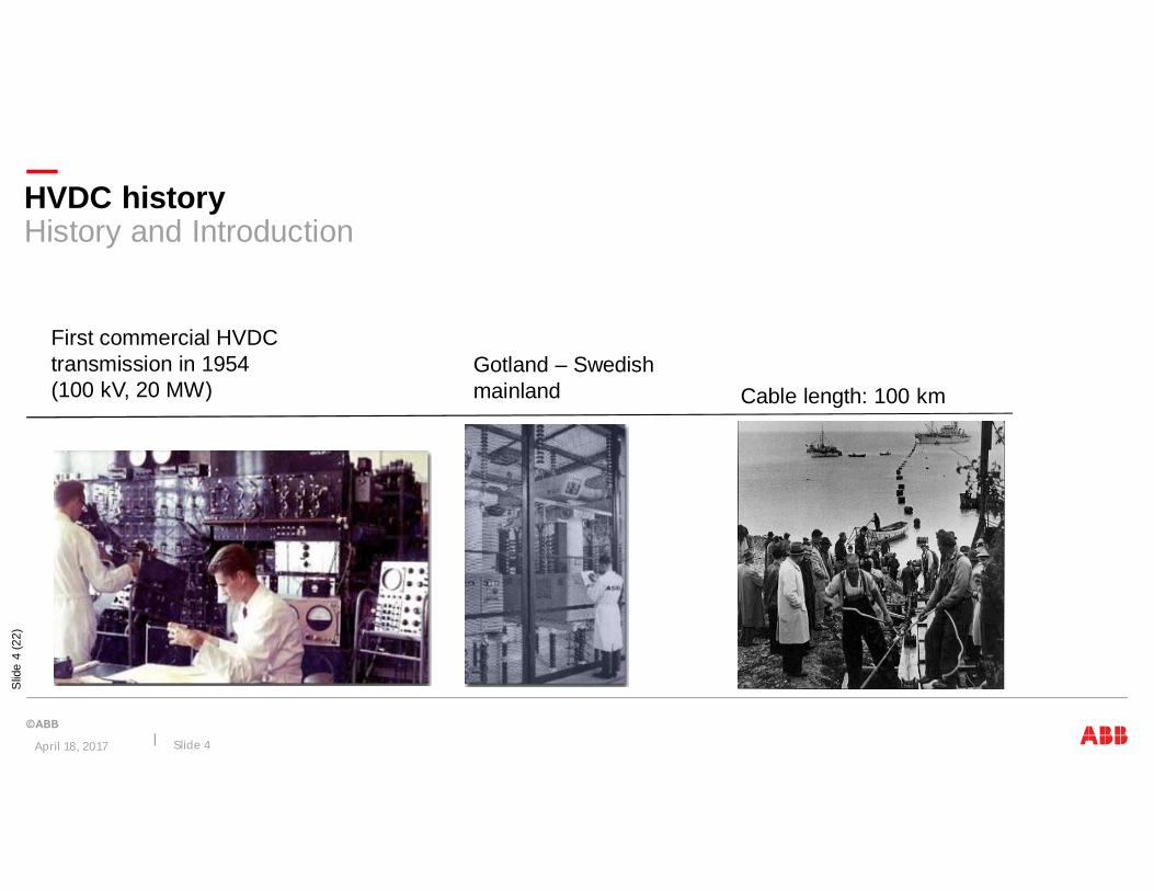
HVDC historyHistory and Introduction
First commercial HVDCtransmission in 1954(100 kV, 20 MW)
Gotland – Swedishmainland Cable length: 100 km
April 18, 2017 Slide 4

HVDC historyABB, the pioneer in HVDC
April 18, 2017 Slide 5
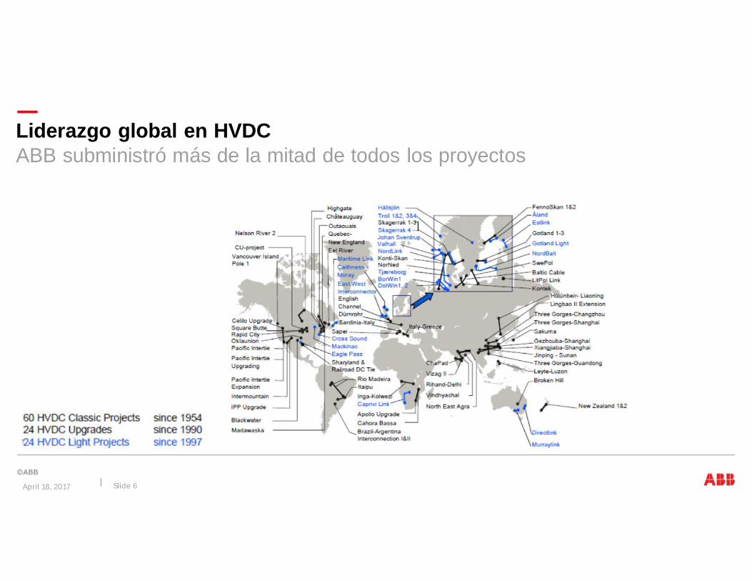
Liderazgo global en HVDCABB subministró más de la mitad de todos los proyectos
April 18, 2017 Slide 6

Opportunities to deliver value to our customers
Power Grids Division
April 18, 2017 Slide 7
Renewables and distributed generation
Longer transmission distances
Power quality
Power grid automation
New grids: emerging markets
Aging grids: developed markets
Service and asset health management
Market drivers
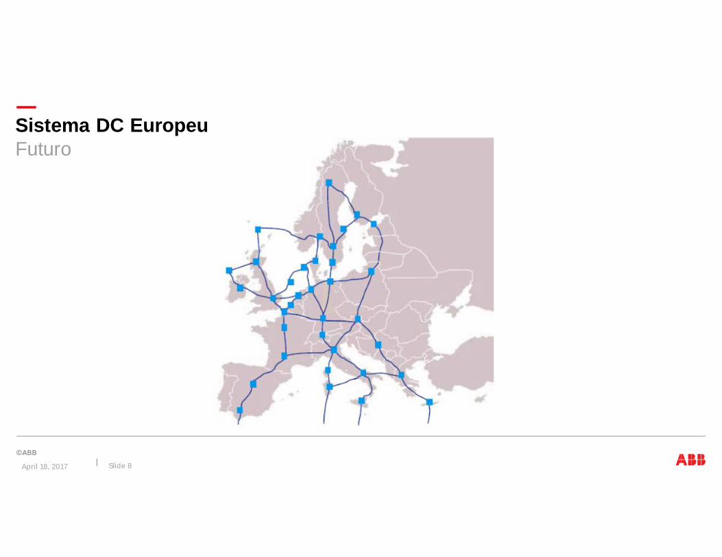
Sistema DC EuropeuFuturo
April 18, 2017 Slide 8

ABB y la Innovación
Porque HVDC
Tecnología HVDC
Experiencia en el Proyecto Rio Madeira, HVDC ± 600 kV
April 18, 2017 Slide 9
Agenda

Slid
e10
(22)
HVDC characteristics
Why use HVDC instead of AC?
DC Decreases total cost for long distance powertransmission with overhead lines and/or cables.DC enables connection between asynchronous AC networks.Gives fast and accurate control of the power flow.
Generator HVDC transmission system Load
April 18, 2017 Slide 10
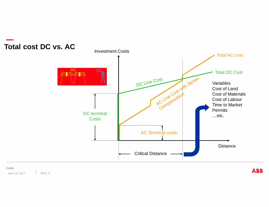
AC Terminal costs
Total AC cost
Total cost DC vs. ACInvestment Costs
Distance
DC terminalCosts
Total DC Cost
VariablesCost of LandCost of MaterialsCost of LabourTime to MarketPermits…etc.
Critical Distance
AC DC
April 18, 2017 Slide 11

Slid
e12
(22)
Lower losses
HVDC 2x500 kV
April 18, 2017 Slide 12

Transmisión ACCamino de la línea aérea
April 18, 2017 Slide 13
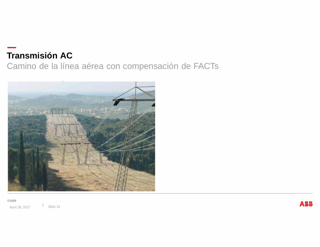
Transmisión ACCamino de la línea aérea con compensación de FACTs
April 18, 2017 Slide 14

Transmisión ACCamino de la línea aérea con compensación de FACTs
April 18, 2017 Slide 15
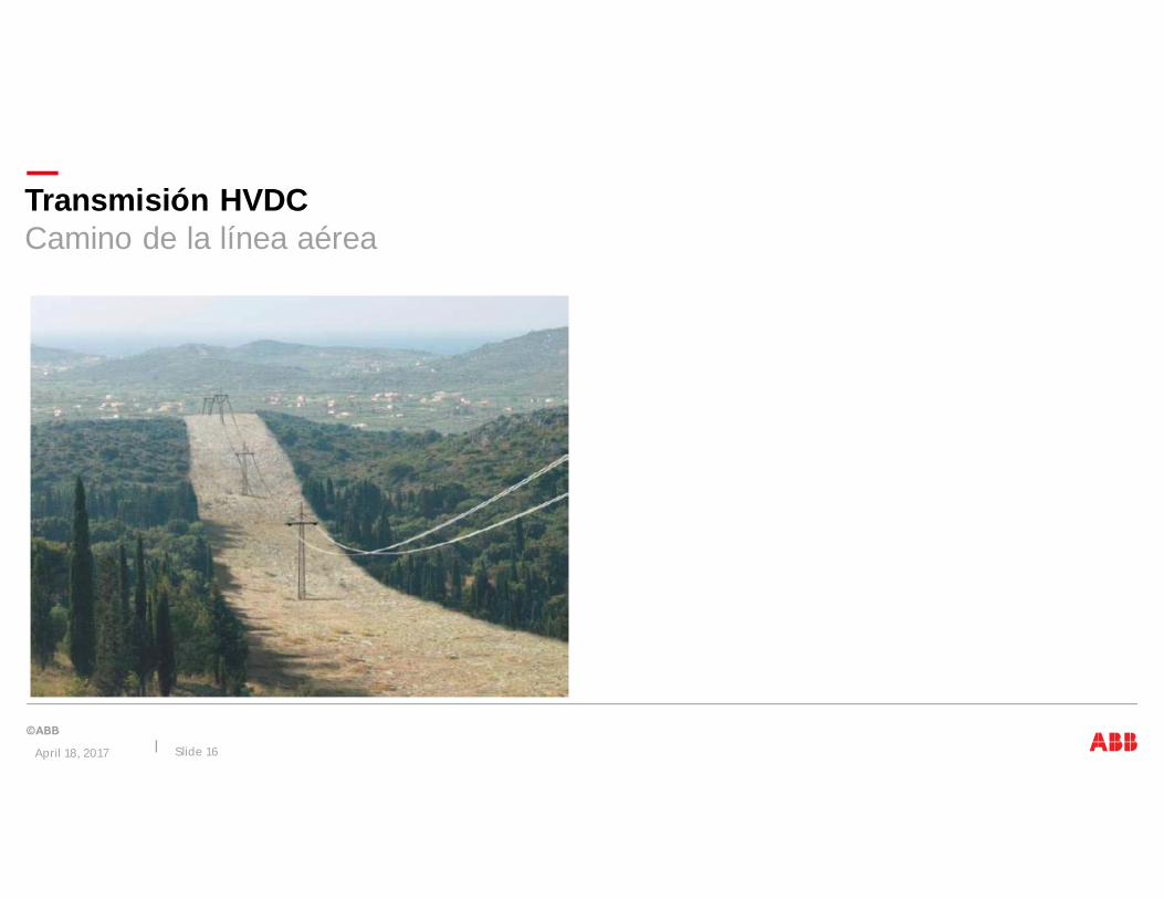
Transmisión HVDCCamino de la línea aérea
April 18, 2017 Slide 16

Transmisión HVDCCamino de la línea aérea
April 18, 2017 Slide 17

Transmisión HVDC LightCamino de cables subterráneos
April 18, 2017 Slide 18
Slid
e19
(22)
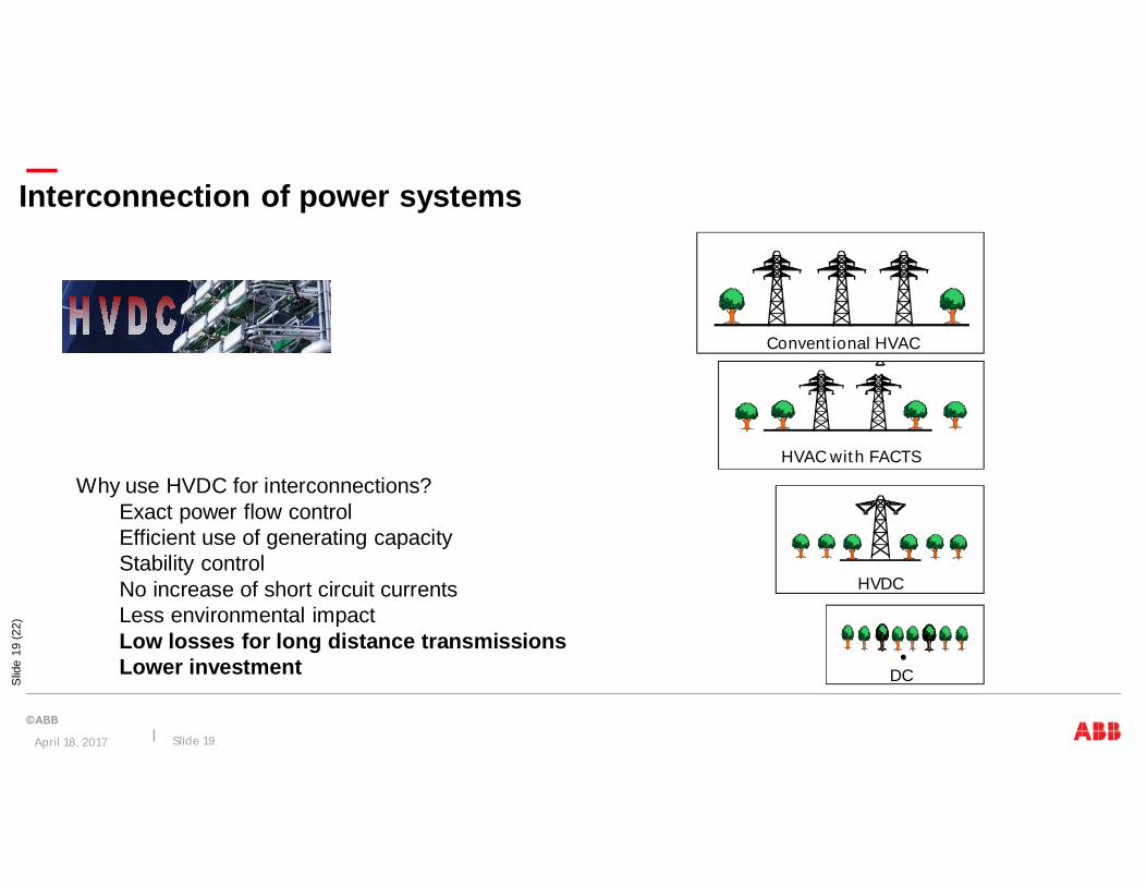
Why use HVDC for interconnections?Exact power flow controlEfficient use of generating capacityStability controlNo increase of short circuit currentsLess environmental impactLow losses for long distance transmissionsLower investment
Interconnection of power systems
DC
HVDC
HVAC with FACTS
Conventional HVAC
April 18, 2017 Slide 19

ABB y la Innovación
Porque HVDC
Tecnología HVDC
Experiencia y aplicaciones
April 18, 2017 Slide 20
Agenda

Thyristor Function
Block high voltage in both directions
Conduct current in forward direction
Turn on when given firing pulse and positive voltage
Turn off when the thyristor current crosses zero
+ Vthyr -
Current direction
April 18, 2017 Slide 21
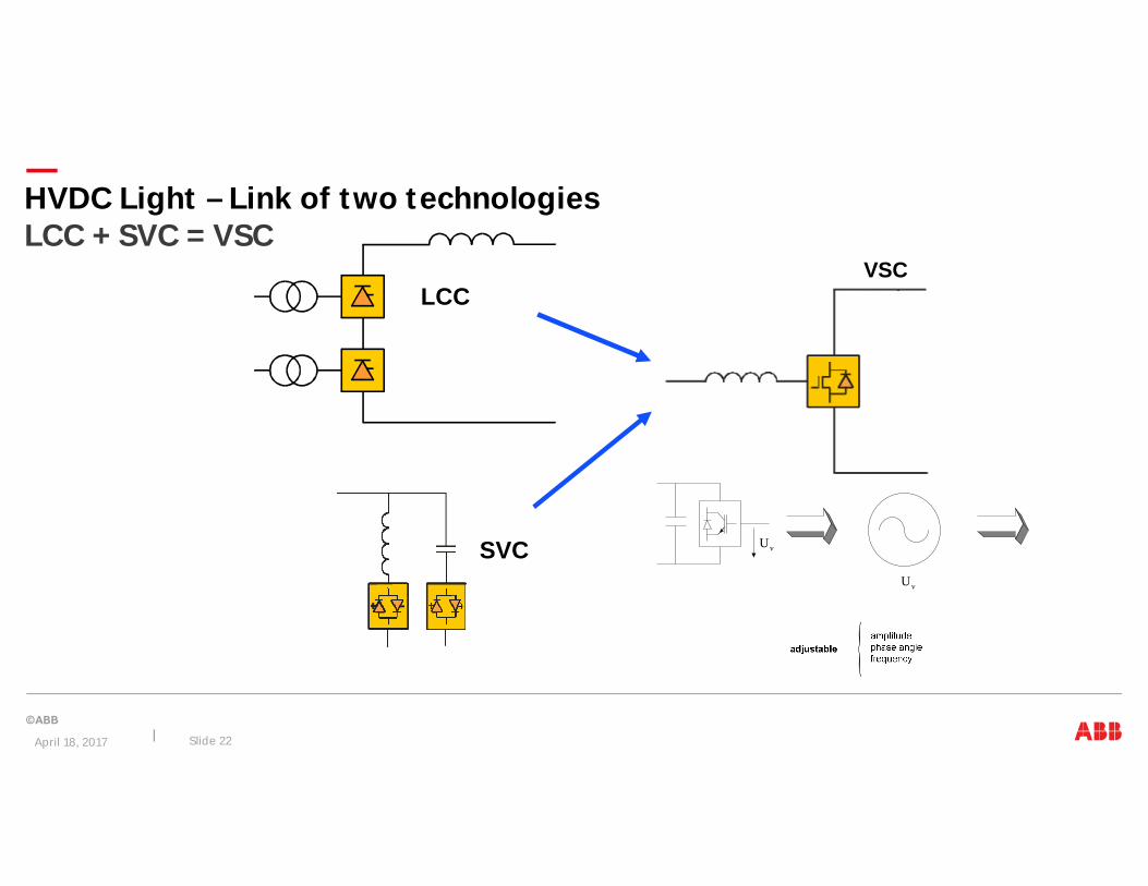
HVDC Light – Link of two technologiesLCC + SVC = VSC
LCC
SVC
VSC
{Uv
Uv
April 18, 2017 Slide 22

Introducción: tipos básicos de ConversorHVDC e HVDC Light
April 18, 2017 Slide 23
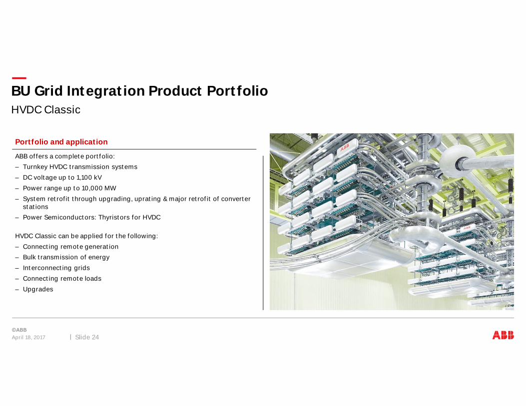
HVDC Classic
BU Grid Integration Product Portfolio
April 18, 2017 Slide 24
ABB offers a complete portfolio:
– Turnkey HVDC transmission systems
– DC voltage up to 1,100 kV
– Power range up to 10,000 MW
– System retrofit through upgrading, uprating & major retrofit of converterstations
– Power Semiconductors: Thyristors for HVDC
HVDC Classic can be applied for the following:
– Connecting remote generation
– Bulk transmission of energy
– Interconnecting grids
– Connecting remote loads
– Upgrades
Portfolio and application

VSC – HVDC Light®
BU Grid Integration Product Portfolio
April 18, 2017 Slide 25
ABB offers a complete portfolio:
– Turnkey HVDC Light® transmission systems
– Land cable, overhead line or sea cable connections
– Power range 50 -1,800 MW
– Power Semiconductors: IGBTs
HVDC Light® can be applied for the following:
– Connecting remote generation, Interconnecting grids, Offshore windconnections
– City center infeed
– Power from shore
– DC links in AC grids
– Connecting remote loads
– Upgrades
Portfolio and application

Tecnologías HVDC - Conversoras
HVDC Light (Conmutación forzada), “VSC”No requiere nivel mínimo de corto-circuitoNo requiere nivel mínimo de potenciaNo demanda potencia reactivaControl independiente de la potencia activa yreactivaSoporte dinámico de voltaje: Q ~= ± 0.5 xPdnom
HVDC Clásico (Conmutación natural), “LCC”Nivel de corto-circuito mínimo: SMVA > 2 x Pd
(>1.3 x Pd con CCC)Nivel mínimo de potencia: 5-10%Demanda potencia reactiva en los terminalesPotencias mas altas, escalas de economía
April 18, 2017 Slide 26

Slid
e27
(22)
HVDC Light: Potencia Activa y ReactivaComparación con HVDC Clásica
1,0
0,5
Id
Q
0,13
- 0,5Consumo de la conversora
Desbalace conla red
Suministro de bancosde capacitores yfiltros
HVDC Clásica:~ compensación reactiva con filtros ybancos en paralelo maniobrados
0.75 0.5 0.25 0 0.25 0.5 0.75
1.25
1
0.75
0.5
0.25
0.25
0.5
0.75
1
1.25P (p.u.)
Qgen
(p.u.)Qabs(p.u.)
Rectifieroperation
Inverteroperation
HVDC Light:No requiere compensación reactiva; STATCOM conun rango dinámico ~ 0.5Pd/+0.5Pd Mvarbajo un factor de potencia de 90%.
Operación individual posible enqualquier punto dentro de la curva(respetando que PR~PI ), i.e. QR y QIpueden ser despachadastotalmente distintas(Diagrama válida en operaciónBtB)
April 18, 2017 Slide 27
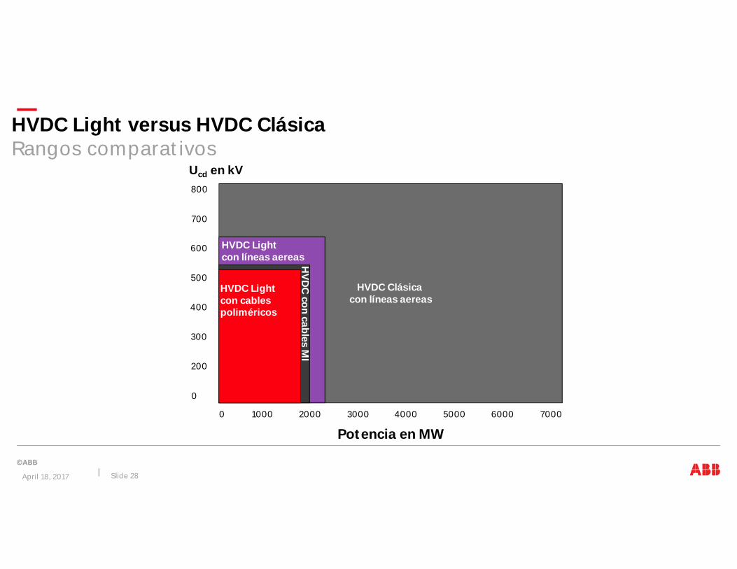
HVDC Light versus HVDC ClásicaRangos comparativos
Ucd en kV
HVDC Clásicacon líneas aereas
Potencia en MW
HVDC Lightcon líneas aereas
800
700
600
500
2000 3000 4000 5000 6000 7000
HV
DC
concables
MI
400
300
200
0
0 1000
HVDC Lightcon cablespoliméricos
April 18, 2017 Slide 28
Slid
e29
(22)
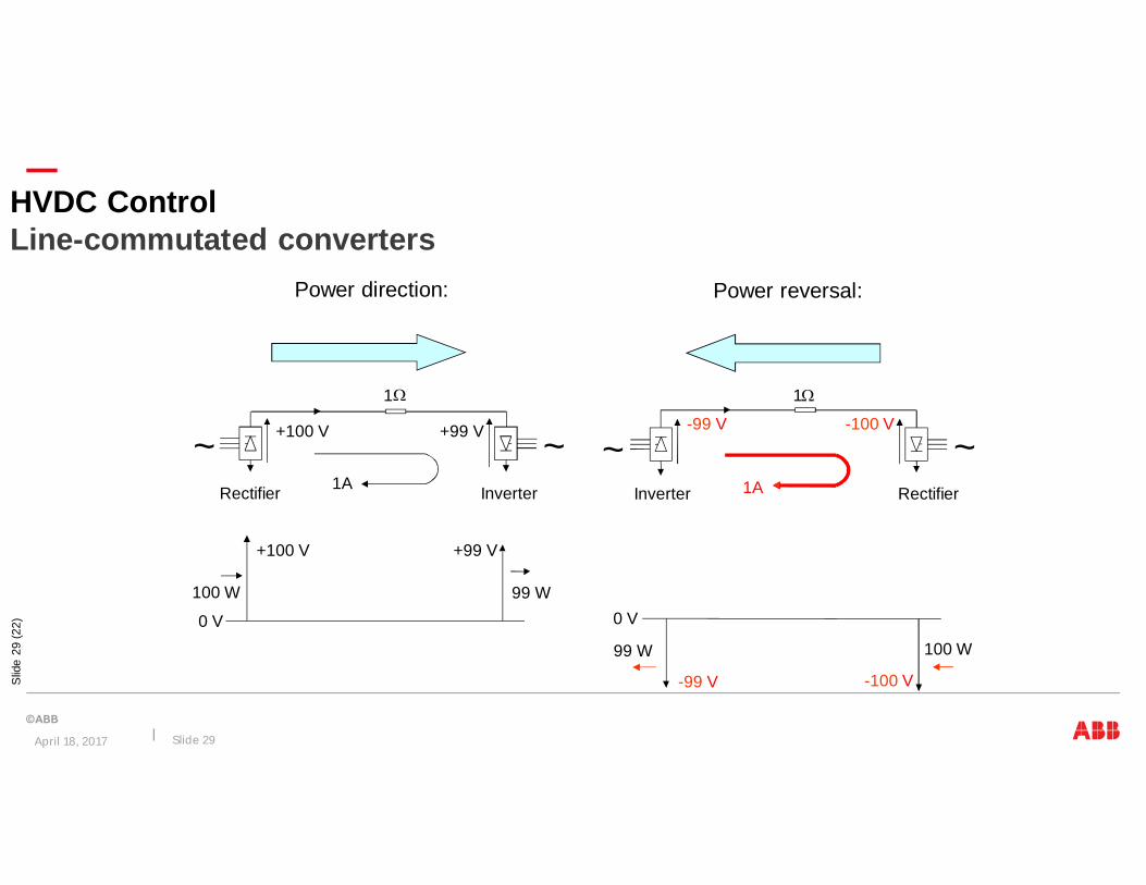
100 W
-100 V
99 W
-99 V
0 V
-99 V -100 V
1A
1W
Inverter Rectifier
~~
Power reversal:
100 W 99 W
+99 V+100 V
0 V
+100 V +99 V
InverterRectifier 1A
~~
Power direction:
1W
HVDC ControlLine-commutated converters
April 18, 2017 Slide 29
Slid
e30
(22)
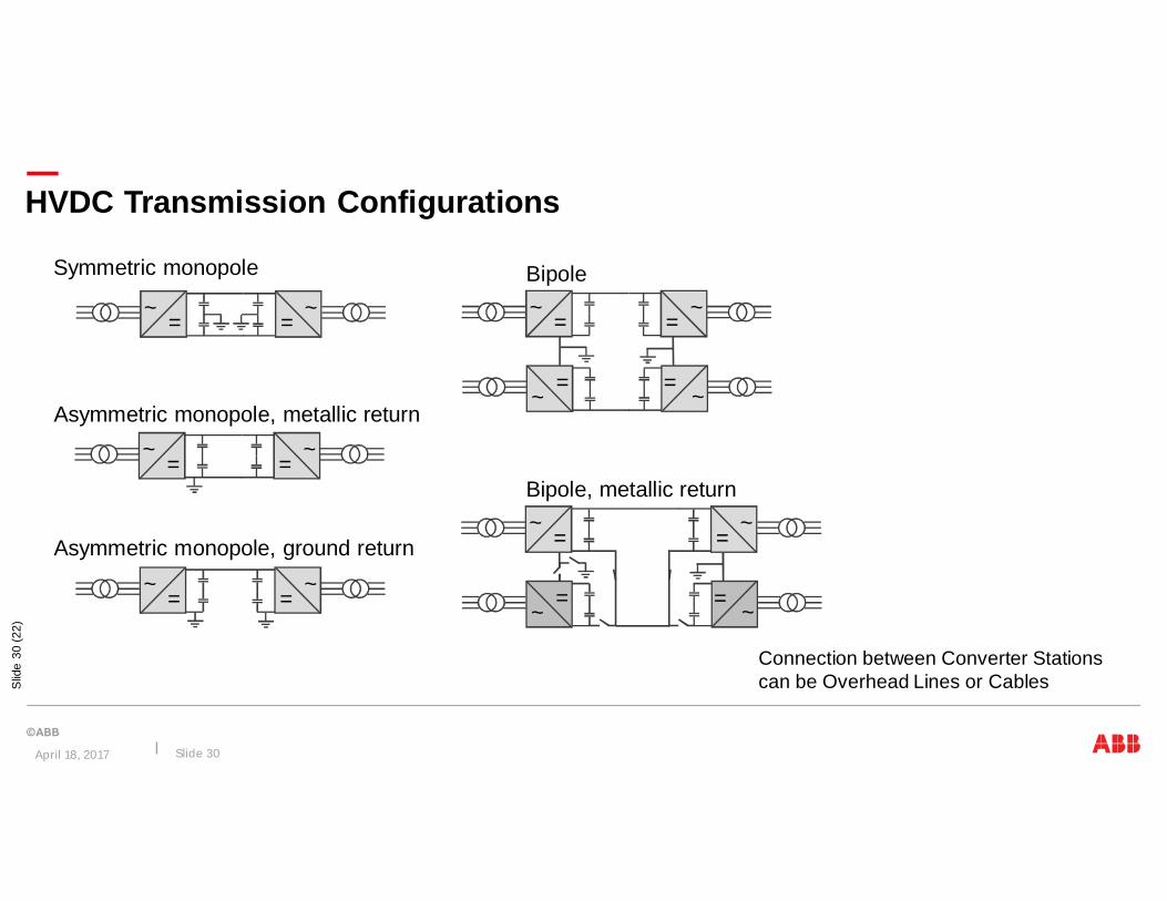
HVDC Transmission Configurations
Connection between Converter Stationscan be Overhead Lines or Cables
=~
=~
Symmetric monopole
=~
=~
Asymmetric monopole, metallic return
=~
=~
=~
= ~
Bipole
Bipole, metallic return
=~
=~
=~ = ~=
~=
~Asymmetric monopole, ground return
April 18, 2017 Slide 30
Slid
e31
(22)
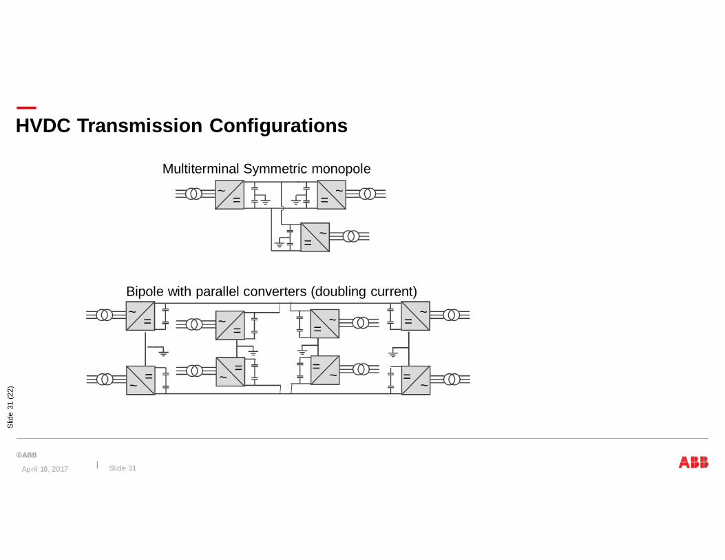
HVDC Transmission Configurations
=~
=~
Multiterminal Symmetric monopole
=~
=~
=~
=~
= ~
Bipole with parallel converters (doubling current)
=~
=~
=~
= ~
April 18, 2017 Slide 31
Slid
e32
(22)
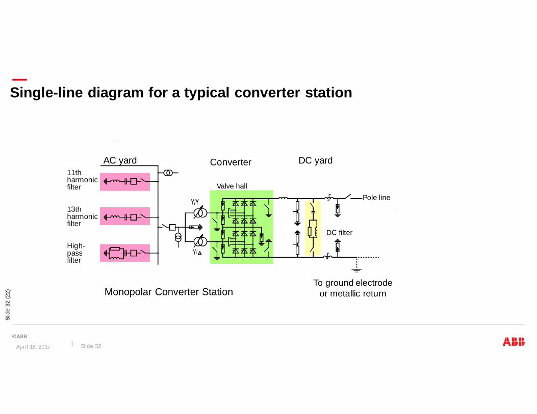
Single-line diagram for a typical converter station
11thharmonicfilter
13thharmonicfilter
High-passfilter
AC yard
Valve hall
Pole line
DC filter
DC yardConverter
To ground electrodeor metallic returnMonopolar Converter Station
April 18, 2017 Slide 32

Slid
e33
(22)
Single-line diagram for a typical converter station
11thharmonicfilter
11thharmonicfilter
13thharmonicfilter
13thharmonicfilter
High-passfilter
High-passfilter
AC yard
Valve hall
AC bus
Pole line
Electrodelines
Pole line
DC filter
DC yardConverter
Pole 1
Pole 2DCFilter
To electrodelines
Bipolar Converter Station
April 18, 2017 Slide 33

Slid
e34
(22)
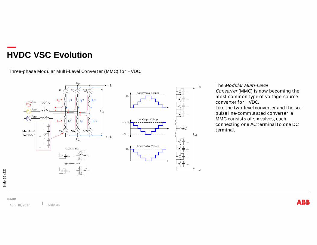
HVDC VSC Evolution
April 18, 2017 Slide 34
Three-phase, two-level voltage-source converter for HVDC
Three-phase, three-level, diode-clamped voltage-source converter for HVDC
The very first VSC-HVDC scheme installed(the Hellsjön experimental linkcommissioned in Sweden in 1997) until 2012,most of the VSC HVDC systems built werebased on the two level converter.
In an attempt to improve on the poor harmonicperformance of the two-level converter. In arefinement of the diode-clamped converter, theso-called active neutral-pointclamped converter, the clamping diode valvesare replaced by IGBT valves, giving additionalcontrollability. Such converters were used onthe Murraylink project in Australia and the CrossSound Cable link in the United States.
Slid
e35
(22)
HVDC VSC Evolution
April 18, 2017 Slide 35
Three-phase Modular Multi-Level Converter (MMC) for HVDC.
The Modular Multi-LevelConverter (MMC) is now becoming themost common type of voltage-sourceconverter for HVDC.Like the two-level converter and the six-pulse line-commutated converter, aMMC consists of six valves, eachconnecting one AC terminal to one DCterminal.

1997Hellsjön± 10 kV, 3 MW
2000Directlink, 354 km± 80 kV, 60 MW
2010DolWin 1, 330 km± 320 kV, 800 MW
2004Estlink, 210 km± 150 kV, 350 MW
Cables HVDC Light
2001Murraylink, 360 km± 150 kV, 220 MW
Para HVDC Light ABB ha desarrollado cables triple-extruidos de bajopeso y con empalmes prefabricados, que:
ØSon probados, secos, confiables y rápidos de montarØNo require búnker de hormigón, sino solamente una
cubierta de arenaØPermite juntar cables con diferentes areas del
conductor 2014± 525 kV, 2600 MW
April 18, 2017 Slide 36
ABB y la Innovación
Porque HVDC
Tecnología HVDC
Experiencia en el Proyecto Rio Madeira, HVDC ± 600 kV
April 18, 2017 Slide 37
Agenda

HVDC Project Map – South America
South AmericaSA 1: Itaipu 2x 3150MW, 600kV, bipole
SA 2: Brazil-Argentina interconetion2x 1100MW, CCC back to backSA 3: Rio Madeira 2x 400MW, CCCback to backSA 4: Rio Madeira 3150MW, 600kV,bipole
April 18, 2017 Slide 38
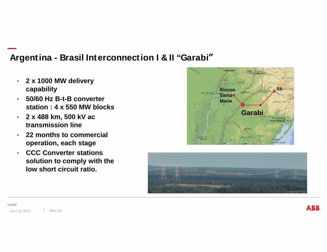
§ 2 x 1000 MW deliverycapability
§ 50/60 Hz B-t-B converterstation : 4 x 550 MW blocks
§ 2 x 488 km, 500 kV actransmission line
§ 22 months to commercialoperation, each stage
§ CCC Converter stationssolution to comply with thelow short circuit ratio.
ItáRinconSantaMaria
Garabi
Argentina - Brasil Interconnection I & II “Garabi”
April 18, 2017 Slide 39
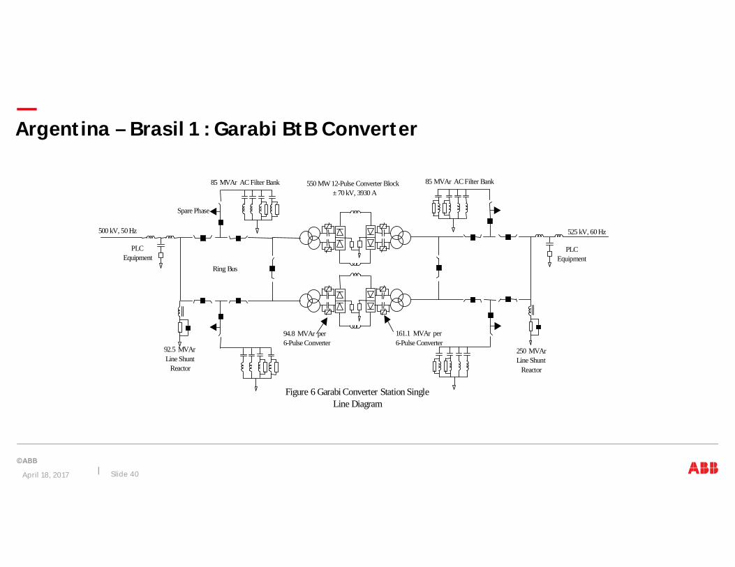
PLC Equipment
500 kV, 50 Hz
PLC Equipment
525 kV, 60 Hz
92.5 MVArLine Shunt
Reactor
250 MVArLine Shunt
Reactor
Spare Phase
550 MW 12-Pulse Converter Block± 70 kV, 3930 A
85 MVAr AC Filter Bank
Ring Bus
161.1 MVAr per6-Pulse Converter
94.8 MVAr per6-Pulse Converter
85 MVAr AC Filter Bank
Figure 6 Garabi Converter Station SingleLine Diagram
Argentina – Brasil 1 : Garabi BtB Converter
April 18, 2017 Slide 40

Line 2
Line 1
Line 2
Line 1
Garabí 2
Block 1
Block 2
Block 3
Block 4
AC filter
Shunt reactor
Garabí 1
Tie-breakersTie-breakers
Argentina - Brasil : Garabi 1 + 2
April 18, 2017 Slide 41

Argentina - Brazil Interconnection I & II “Garabi”
Garabi Converter AreaTransformers,Valve Modules,CCC Capacitors
2x550 MW Blocks
Garabi Valve Modules,± 70 kV4000 A
April 18, 2017 Slide 42

60 Hz
50 Hz
550 MWBlock 1
550 MWBlock 2
Argentina - Brasil : Garabi BtB Converter
April 18, 2017 Slide 43
• Distributed containers withcontrol systems close to the yard
• Optical CV and VTs• Optical DCCT• CCC Capacitors Banks

Argentina - Brasil : Garabi BtB Converter
Valve Modules3xQuadrivalve
CCC capacitors
CCC capacitors
ConverterTransformers
April 18, 2017 Slide 44

Argentina - Brasil : Garabi 1 + 2
April 18, 2017 Slide 45
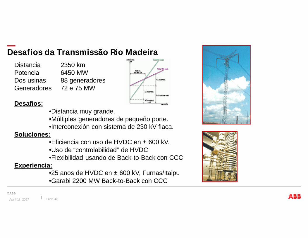
Desafios da Transmissão Rio MadeiraDistancia 2350 kmPotencia 6450 MWDos usinas 88 generadoresGeneradores 72 e 75 MW
Desafíos:•Distancia muy grande.•Múltiples generadores de pequeño porte.•Interconexión con sistema de 230 kV flaca.
Soluciones:•Eficiencia con uso de HVDC en ± 600 kV.•Uso de “controlabilidad” de HVDC•Flexibilidad usando de Back-to-Back con CCC
Experiencia:•25 anos de HVDC en ± 600 kV, Furnas/Itaipu•Garabi 2200 MW Back-to-Back con CCC
April 18, 2017 Slide 46

Bipole 1± 600 kV line
Lot D
CPV stationBtB 2x400 MW
Lot A
Bipole 23150 MW
Lot F
Sistema de Transmisión del Rio Madeira
Bipole 13150 MW
Lot C
Bipole 2± 600 kV line
Lot G
April 18, 2017 Slide 47
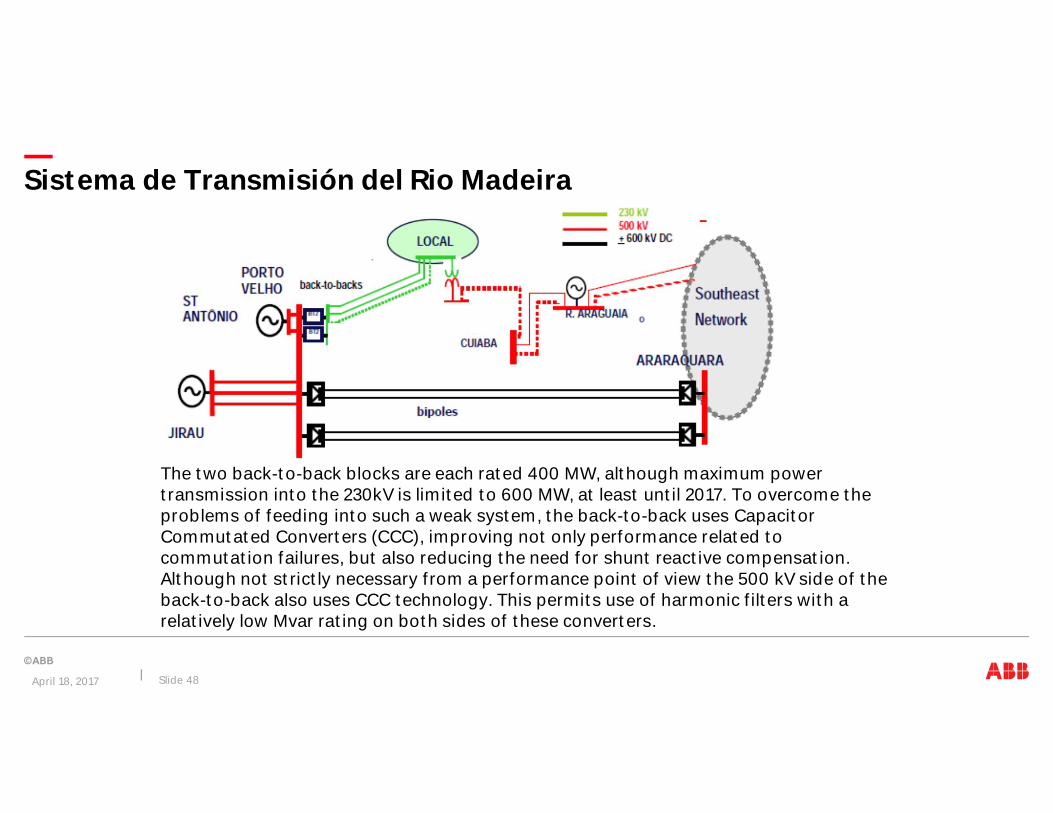
Sistema de Transmisión del Rio Madeira
The two back-to-back blocks are each rated 400 MW, although maximum powertransmission into the 230kV is limited to 600 MW, at least until 2017. To overcome theproblems of feeding into such a weak system, the back-to-back uses CapacitorCommutated Converters (CCC), improving not only performance related tocommutation failures, but also reducing the need for shunt reactive compensation.Although not strictly necessary from a performance point of view the 500 kV side of theback-to-back also uses CCC technology. This permits use of harmonic filters with arelatively low Mvar rating on both sides of these converters.
April 18, 2017 Slide 48
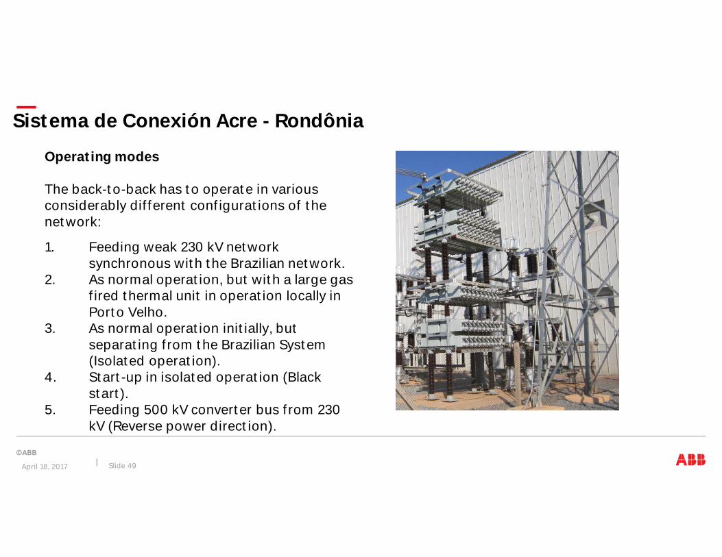
Operating modes
The back-to-back has to operate in variousconsiderably different configurations of thenetwork:
1. Feeding weak 230 kV networksynchronous with the Brazilian network.
2. As normal operation, but with a large gasfired thermal unit in operation locally inPorto Velho.
3. As normal operation initially, butseparating from the Brazilian System(Isolated operation).
4. Start-up in isolated operation (Blackstart).
5. Feeding 500 kV converter bus from 230kV (Reverse power direction).
Sistema de Conexión Acre - Rondônia
April 18, 2017 Slide 49

Notes:Includes metallic return, paralleling of bipoles and of linesLot C includes Master Control of Back-to-Back and Bipole 2
Bipolo 1, 3150 MW Rio Madeira Transmisión, Lote C
Porto Velho Araraquara
April 18, 2017 Slide 50

Conversoras da Transmissão em HVDC
CPV Bipole 1 Valve Hall
QuadrivalvulasTrasformadores de tres enrolamientos
April 18, 2017 Slide 51
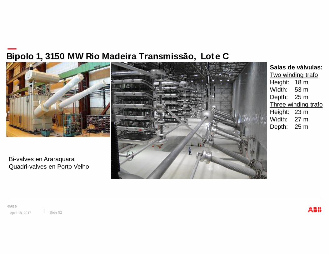
Bi-valves en AraraquaraQuadri-valves en Porto Velho
Bipolo 1, 3150 MW Rio Madeira Transmissão, Lote CSalas de válvulas:Two winding trafoHeight: 18 mWidth: 53 mDepth: 25 mThree winding trafoHeight: 23 mWidth: 27 mDepth: 25 m
April 18, 2017 Slide 52
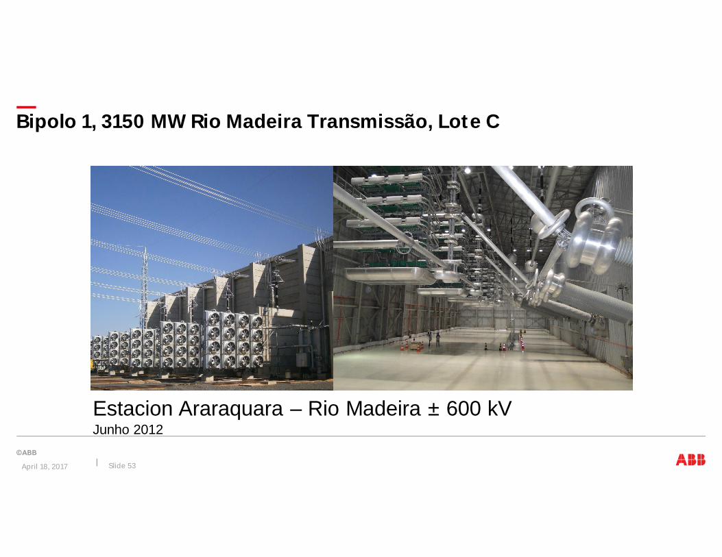
Bipolo 1, 3150 MW Rio Madeira Transmissão, Lote C
Estacion Araraquara – Rio Madeira ± 600 kVJunho 2012
April 18, 2017 Slide 53

Largest HVDC transformerSingle phase 3 winding
Power: 621/310,5/310,5 MVAConnection: Yn/Y/D
HVDC transformers
April 18, 2017 Slide 54

Rio Madeira TransmissionTransporte transformadores para Porto Velho, via Manaus
April 18, 2017 Slide 55
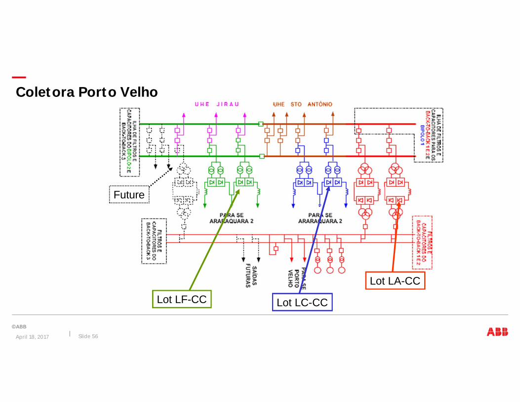
Coletora Porto Velho
Lot LA-CC
Lot LF-CC Lot LC-CC
Future
April 18, 2017 Slide 56
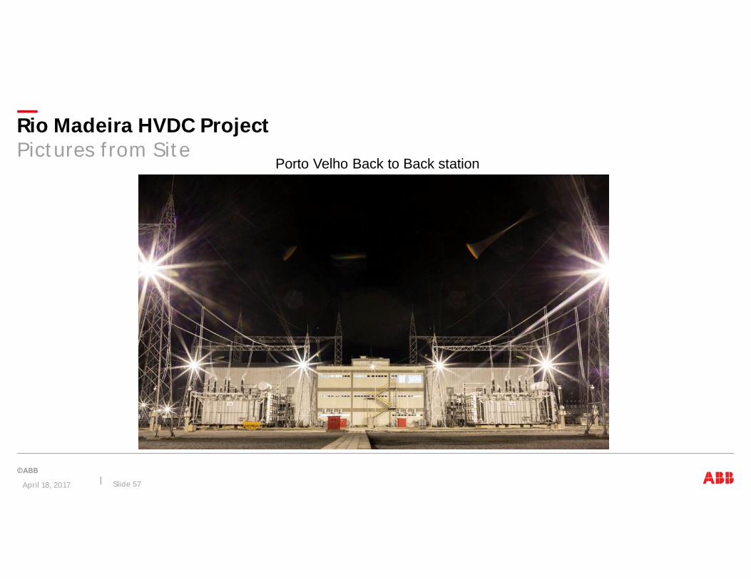
Rio Madeira HVDC ProjectPictures from Site
Porto Velho Back to Back station
April 18, 2017 Slide 57
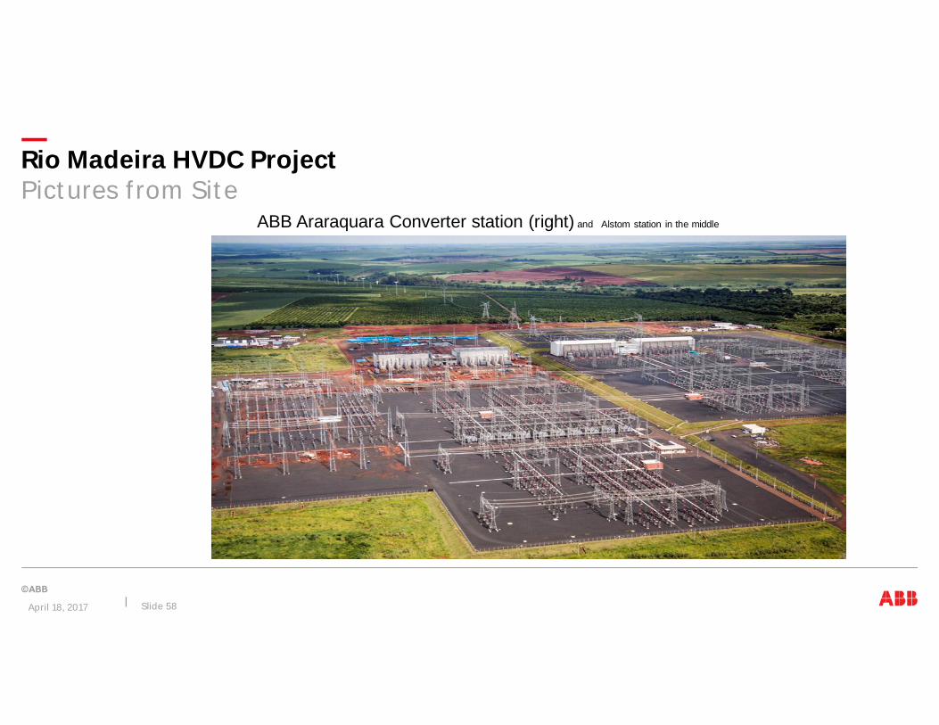
ABB Araraquara Converter station (right) and Alstom station in the middle
Two transformers moved into position
Rio Madeira HVDC ProjectPictures from Site
April 18, 2017 Slide 58

Coletora Porto Velho
April 18, 2017 Slide 59

BtB 1, 400 MW Rio Madeira Transmissão, Lote ATeste de tipo, Octo-Valvula
CCC, Transformador de três fases, Octo-valvulas ± 50 kV
April 18, 2017 Slide 60
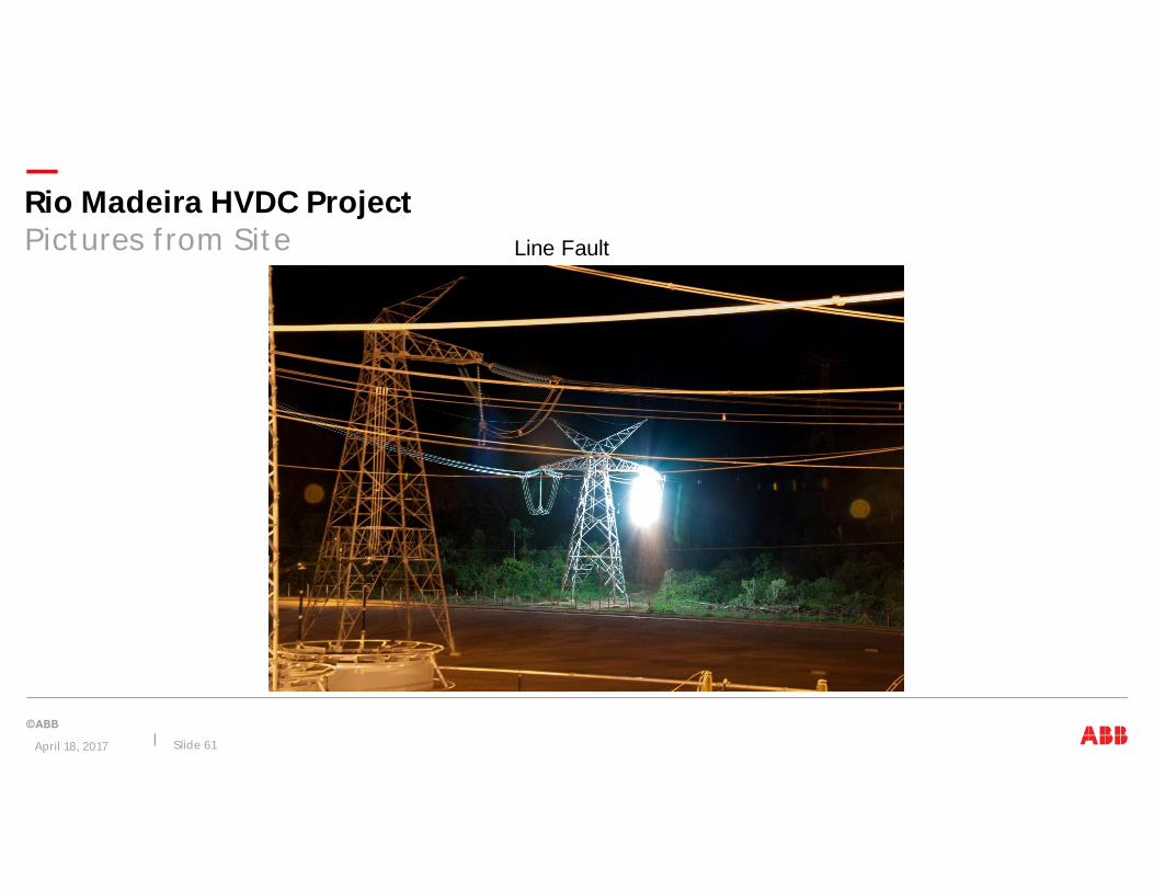
Line Faulttest
Rio Madeira HVDC ProjectPictures from Site
April 18, 2017 Slide 61

T. Rio
BeloMonte
Madeira
Araraquara
Itaipu
Int. N – SParauapebas
Assis
Estreito
Int NE – SEGraçaAranha
Silvania
Proyectos futuros en Brasil
April 18, 2017 Slide 62
Tapajos
Bipoles A & B
Tapajos 1 & 2HPP Tapajós Transmission System
Voltage: ± 800 kV DC
Power: 8,000 MW for 2 bipoles
Expected Auction/Award: 2019/2020BP1 2020/2021 BP2
Transmission Line: 1,500 km BP12,500 km BP2
N/SE and NE/SE Transmission Expansion
Transmission Line: 2,100 km N/SE1,500 km NE/SE
Voltage: ± 800 kV DC
Power: 7,500 MW for 2 bipoles
Expected Auction/Award: 2018/2019

Cuando y porque usar ellos de CorrienteContinua?
1. Menos costo de inversión2. Distancias longas3. Perdidas menores4. Interconexiones asíncronas5. Flexibilidad de controle6. Limitación de corrientes de corto7. Medio-ambiente
SumarioMais eficienteMais robustoMenos impacto ambiental
Razones para el uso de HVDC.
April 18, 2017 Slide 63

Contactos
April 18, 2017 Slide 64
Felipe NobreGerente de Grid IntegrationTeléfono: +56 2 2471 4322Celular: +56 9 4432 3687E-mail: [email protected]