applications and programming guide - jr … aerobatic airplane, ... any open auxiliary channel. the...
TRANSCRIPT

1
APPLICATIONS AND PROGRAMMING GUIDE
12-CHANNEL COMPUTER RADIO SYSTEM WITH SPEKTRUM 2.4GHz DSM
TECHNOLOGY

2
Programming a model for the first time, especially with a new radio, can be confusing. Following are programming guides that give step-by-step instructions for programming a giant-scale aerobatic airplane, an aircraft with dual flap setup, a Helicopter with CCPM mixing and a full function sailplane. Within each section, information is provided to program various flap options, heading lock and conventional gain gyros,
programming a governor and programming a countdown timer to start on throttle up. While there are an endless number of programming methods and options, the following setup guide provides the fundamental basis from which to build upon. Important: This Applications Guide is intended to be used as a supplement to the manual. For further details regarding programming specifics please refer to the manual.
Following is a step-by-step programming guide for Giant-Scale aerobatic aircraft. The specific example below gives setup details for an aircraft with 4 aileron servos, 2 elevator servos, and 2 rudder servos. Included is information on programming a countdown timer to be activated upon throttle up. While this setup guide is specific to Giant-Scale aircraft, setup of other types will be similar.
Use the following to locate the correct locations for the servos:
Programmable Smoke System- Channel 10/ Aux5
Rudder Servo 2- Channel 9/ Aux4
Left Aileron Servo 2- Channel 8/ Aux3
Right Aileron Servo 2- Channel 7/ Aux2
Left Elevator Servo- Channel 6/ Aux1
Left Aileron Servo 1- Gear CH5
Rudder Servo 1- Rudder CH4
Right Elevator Servo- Elevator CH3
Right Aileron Servo 1- Aileron CH2
Throttle Servo- Throttle CH1
Introduction
Giant-Scale Aerobatic Aircraft Setup Guide
Servo Connections
3
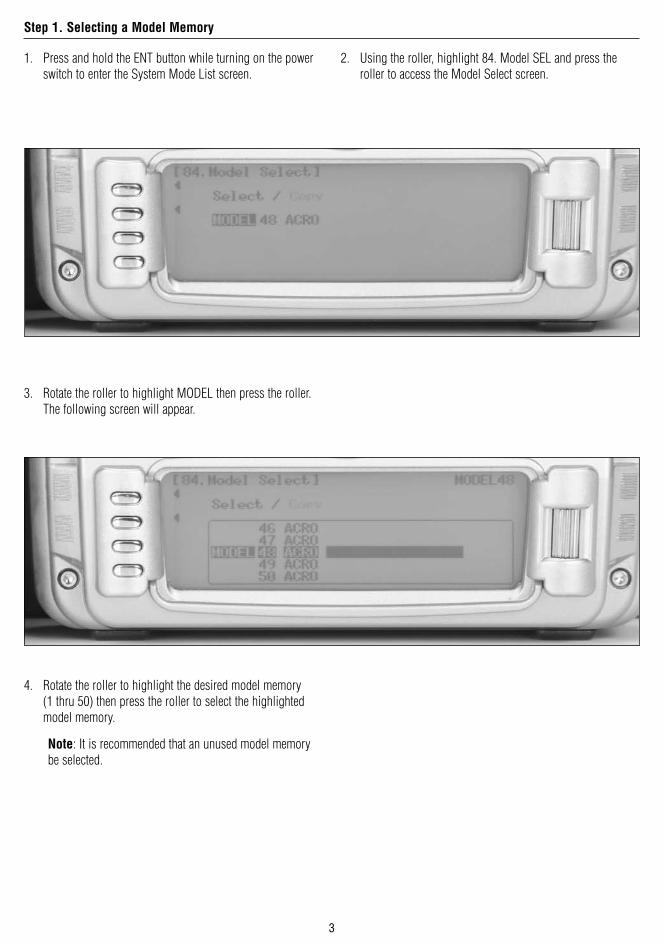
1. Press and hold the ENT button while turning on the power switch to enter the System Mode List screen.
2. Using the roller, highlight 84. Model SEL and press the roller to access the Model Select screen.
3. Rotate the roller to highlight MODEL then press the roller. The following screen will appear.
4. Rotate the roller to highlight the desired model memory (1 thru 50) then press the roller to select the highlighted model memory.
Note: It is recommended that an unused model memory be selected.
Step 1. Selecting a Model Memory

4
1. In System Mode List screen use the roller to highlight 89. Type SEL. and press the roller to access the Type Select screen.
2. Rotate the roller to highlight ACRO then press the roller to enter the ACRO program.
1. In System Mode List screen use the roller to highlight 28. MDL Reset and press the roller to access the Model Reset screen.
2. Press the RESET button, then press YES to reset the model memory to Factory Default settings.
Note: All programming in the selected model memory will be reset to factory defaults.
Note: All programming in the selected model memory will be reset to factory defaults.
Step 2. Selecting the Model Type (Acro)
Step 3. Resetting the Model Memory

5
1. In System Mode List screen use the roller highlight 81. MDL Name and press the roller to access the Model Name screen.
2. Rotate the roller to select the desired position to place a letter or number (up to 16 characters) and press the roller to access the Character screen.
3. Rotate the roller to select the desired number or letter and press the roller to transfer that character to the selected position.
4. Repeat until naming is complete. Press LIST to return to the System mode list.
Step 4. Naming the Model

6
The Trim System Code 83 allows the adjustment of the trim authority and also allows the flap trim and aux trim levers to be turned on or off. An LST function when turned on causes the aileron, elevator and rudder trim levers to only affect the center and not affect the endpoints, which is desired for aircraft to prevent over-driving the servos when trim is used. For most 40% aerobatic aircraft it is recommended to turn the flap trim
and aux trim off. The remaining settings are recommended to be left at the default settings, 100% throttle, 4 for Aileron, Elevator, and Rudder, and leave LST turned on. Once the aircraft is trimmed using the default settings, the trim rate for Aileron, Elevator, and Rudder can be reduced to 1 to allow for fine adjustments of trim to perfectly trim the aircraft in flight.
Note: If a large amount of trim is required for the model, LST trims will reduce the amount of throw in the direction of the trim, and reduce control effectiveness in that direction.
1. In System Mode List screen use the roller to highlight 83. Trim SYS and press the roller to access the Trim System screen.
2. Highlight ON next to Flap Trim and press the roller to change this to OFF.
3. Highlight ON next to Aux Trim and press the roller to change this to OFF. All other settings in Trim System should be left in their factory default values.
Trim System
Step 5. Setting Up the Trim System

7
The flight mode name function code 92 can be used to rename the flight modes throughout the system. This allows customized programming for at-a-glance awareness of the current flight mode. For instance Flight Mode 0 can be renamed 3-D, Flight
Mode 1 can be renamed SNAP, and Flight Mode 2 can be renamed NORMAL (NORM). A short name can then be selected from the complete flight mode name. Throughout the system, the short name will be used as the name of the flight mode in functions such as program mixes and other functions.
1. In System Mode List screen use the roller to highlight 92. FM Name and press the roller to access the FM Name screen.
2. Rotate the roller and highlight the first character, press the roller, then rotate the roller to select the desired character. Press the roller to select the desired character, and repeat for each flight mode as desired. The Flight Mode name can be up to 6 characters long.
Flight Mode Naming
Step 6. Flight Mode Naming

8
3. Rotate the roller and highlight the * and – marks as desired under each Flight Mode name to select the abbreviated short name. A * mark indicates the character will be used in the short name, a – mark indicates the character will not be used in the short name. The short name can be up to 4 characters long.

9
Device Select code 17 allows the activation of flight modes, selecting a throttle hold switch, flap trim selection, flight mode trim selection, and switch selection and activation for all aux channels. Generally it is recommended for most aircraft to begin setting up the aircraft by inhibiting all aux channels in Device Select so that they can be used for dual functions in the Wing Type menu. Flight modes can be activated in Device Select; many flyers prefer to use the elevator dual rate switch as the flight mode switch, though there are several switch options that can be selected. Extra Flight modes (5 instead of
3) can be activated as well in the Device Select function, using 2 switches combined to select the desired flight mode in flight. Generally most fliers use 3 flight modes. Flight mode trims can be activated in Device Select. With Flight mode trims on, trims will be independent for all flight modes, which allows the aircraft to be trimmed in each flight mode. If the aircraft requires different trim settings in each flight mode, activate this function. Generally most giant-scale aerobatic aircraft do not require different trim settings for each flight mode, so this is generally turned off.
Note: If flight mode trims are active, it will be necessary to trim the aircraft in all flight modes independently.
1. Press and hold the ENT button while turning on the power switch to enter the System Mode List screen.
2. Using the roller highlight 17. DeviceSEL and press the roller to access the Device Select screen.
Device Select
Step 7. Device Select Setup

10
3. Rotate the roller to highlight INH next to Flight Mode then press the roller. The available switch positions screen will appear.
4. Rotate the roller to select the Elevator D/R switch then press the roller to select it. If another switch is desired, choose it in the same manor.
5. Rotate the roller to highlight ACT next to Gear then press the roller. The available functions list will appear.
6. Rotate the roller to select INH. Repeat for all the remaining Aux channels.
11
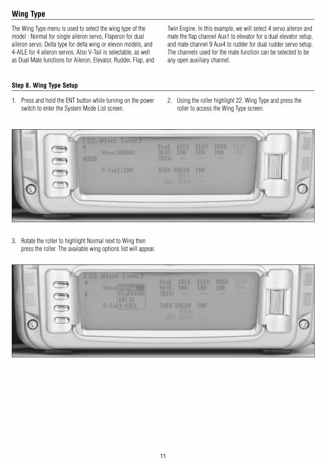
Twin Engine. In this example, we will select 4 servo aileron and mate the flap channel Aux1 to elevator for a dual elevator setup, and mate channel 9 Aux4 to rudder for dual rudder servo setup. The channels used for the mate function can be selected to be any open auxiliary channel.
The Wing Type menu is used to select the wing type of the model : Normal for single aileron servo, Flaperon for dual aileron servo, Delta type for delta wing or elevon models, and 4-AILE for 4 aileron servos. Also V-Tail is selectable, as well as Dual Mate functions for Aileron, Elevator, Rudder, Flap, and
1. Press and hold the ENT button while turning on the power switch to enter the System Mode List screen.
2. Using the roller highlight 22. Wing Type and press the roller to access the Wing Type screen.
3. Rotate the roller to highlight Normal next to Wing then press the roller. The available wing options list will appear.
Wing Type
Step 8. Wing Type Setup

12
5. Rotate the roller and highlight INH under ELEV and press the roller.
4. Rotate the roller and highlight 4-Aile and press the roller.
6. Rotate the roller and highlight FLAP and press the roller.
7. Rotate the roller and highlight INH under RUDD and press the roller.
8. Rotate the roller and highlight AUX4 and press the roller.

13
1. With the system installed in the aircraft, insert the bind plug in the bind receptacle.
2. Turn on the receiver switch. Note that the LED’s on all receivers should be flashing, indicating that the receiver is ready to bind.
3. Establish the desired fail-safe stick positions: normally low throttle and aileron, elevator and rudder at neutral.
4. Press and hold the bind button on the back of the transmitter while turning on the power switch. Within a few seconds the system should connect. The LED’s on the receivers should go solid, indicating the system has connected.
5. Remove the bind plug and store it in a convenient place.
6. After you’ve programmed your model, it’s important to rebind the system so the true low throttle and neutral control surface positions are programmed.
1. In the Function List screen use the roller to highlight 11. REV. SW and press the roller to access the Reverse switch screen.
2. Rotate the roller to highlight the desired channel that you wish to reverse and press the roller to reverse that channel. Repeat this for all channels.
Step 9. Binding
Step 10. Servo Reversing

14
1. In the Function List screen use the roller to highlight 12. TRVL adjust and press the roller to access the Travel adjust screen.
2. Rotate the roller to highlight the desired channel that you wish to adjust the travel adjust and press the roller to access that channel. Move the corresponding stick or switch in the desired direction to highlight the value for that direction, then rotate the roller to adjust the travel adjust value for that direction.
Note: For most aircraft, the best mechanical advantage is to set the travel adjust to 125% or higher and adjust the mechanical setup on the aircraft to achieve the proper throw. To increase travel mechanically, either move out on the servo arm or in on the control horn; to decrease travel mechanically move in on the servo arm or out on the control horn. Keep in mind that moving out on the servo arm or moving in on the control horn reduces the mechanical advantage of the surface, and an improper mechanical setup can lead to flutter.
Most giant-scale aircraft pilots use different dual rates and expo for each flight mode to customize the aircraft feel and performance in each flight mode. For instance in 3-D Flight mode, generally the Dual rate is set to 100% or higher, and the Expo is generally set to 50% or higher to soften the feel of the aircraft at center, which makes the aircraft fly normally around center, but then allows for 3D control rates at full stick deflection. Alternately, for SNAP mode, generally the rates
are set low for elevator and rudder, and higher for aileron to improve snap roll performance, with moderate expo on aileron and lower expo on elevator and rudder. In normal flight mode, generally the rates and expo are set to comfortably fly a sequence or basic aerobatics smoothly with low rates and low expo values. Rates and Expo can be custom tailored to each pilot‘s own desired feel for each aircraft and often vary from pilot to pilot and aircraft to aircraft.
Step 11. Travel Adjust
Dual Rate and Exponential

15
1. In the Function List screen use the roller to highlight 13. D/R & EXP and press the roller to access the Dual Rate and Expo screen.
2. Rotate the roller to highlight the channel in the upper left of the screen and press the roller. Select AILE, ELEV or RUDD by pressing the roller.
3. Rotate the roller to highlight the desired D/R value. Note the positions (POS0, POS1, POS2) are activated via the corresponding D/R switch or Flight Mode Switch if selected. Press the roller to select, rotate the roller to set the value and press the roller to select. Moving the stick in either direction will select direction if a different rate is desired in each direction.
4. Rotate the roller to highlight the desired EXP value. Note the positions (POS0, POS1, POS2) are activated via the corresponding D/R switch or Flight Mode Switch if selected. Press the roller to select, rotate the roller to set the value and press the roller to select. Moving the stick in either direction will select direction if a different rate is desired in each direction.
1. In the Function List screen use the roller highlight 15. Sub Trim and press the roller to access the Sub Trim screen.
2. Rotate the roller to highlight the desired channel that you wish to adjust the sub trim and press the roller to access that channel.
3. If necessary adjust the sub trim for all channels. Note that minimal subtrim should be used. When possible, reposition the servo horn on its spline to an improved position that will require the least amount of sub trim.
Step 12. Adjusting Rate and Expo Values
Step 13. Sub Trim

16
1. In the Function List screen use the roller to highlight 16. THRO Hold and press the roller to access the Throttle hold screen.
2. Rotate the roller and highlight INH then press the roller to access the throttle hold screen and activate throttle hold.
3. Rotate the roller to select the HOLD Pos. then press the roller. Rotate the roller to program the throttle hold position. Adjust the throttle hold position so that either the throttle does not move with the throttle stick at low and the throttle trim at the normal flight position, or if a throttle kill function is desired, adjust the value such that the throttle servo moves the throttle back to kill the engine.
Step 14. Activating Throttle Hold

17
1. In the Function List screen use the roller to highlight 18. THRO CURV and press the roller to access the all servos hold screen. Press YES or NO to access the Throttle Curve screen.
2. If you wish to have different throttle curves selected via a switch or flight mode, rotate the roller to highlight SW SEL and press the roller. Rotate the roller to highlight the desired switch or flight mode and press the roller. To switch between throttle curves on the throttle curve screen once selected, move the selected switch to the desired position.
3. Rotate the roller to highlight the desired point that you wish to change (L, 1 or H) then press the roller to access that point.
4. Rotate the roller to adjust to throttle curve at the selected point.
5. To add additional points in the curve, move the throttle stick to the area desired until the STOR option appears on the bottom left side of the screen. Press the bottom button on the left to store a point at this location. Adjust the value as described in the above steps.
Step 15. Programming Throttle Curves

18
When Ailerons are deflected, the Aileron that deflects downward typically creates more drag than the Aileron that deflects upward. If the difference in drag is great enough, it will cause the aircraft to yaw in the direction of the down Aileron, i.e. a roll to the right will cause the aircraft to yaw to the left because the left Aileron deflects downward and creates more drag. This, of course, is an undesirable tendency that results in non-axial rolls and a loss of heading. The Aileron Differential function
allows adjustment of the Aileron that deflects downward without affecting the Aileron that travels upward and, therefore, can eliminate yaw tendencies in rolling maneuvers. It can also affect only the Aileron that travels upward—this is called negative differential and is useful if an aircraft yaws in the same direction as the Aileron input. Most aircraft require a small percentage of positive differential, though composite aircraft that are top skin hinged require a small percentage of negative differential.
1. In the Function List screen use the roller to highlight 32. DIFFERN. and press the roller to access the Differential screen.
2. Rotate the roller to highlight Pos.0 and press the roller to select.
3. Rotate the roller to adjust the value and press the roller to select. Adjust this value in flight to make the aircraft roll axially with aileron input.
4. If desired, 2 differential settings are available by rotating the roller to select SW SEL and press to select. Then select the switch or flight mode desired to select. Once selected, set the Pos.0 and Pos.1 values as desired. Generally only a single differential setting is required.
Step 16. Programming Aileron Differential

19
The balance function is used to adjust the throw of dual servo setups or quad aileron servo setups to fine-tune the throws of the channels to equal one another throughout the servos movement. This function is especially useful for matching multiple servos on a single aileron or rudder, however, has benefits for matching throws between elevator halves and similar functions. Note that the Balance screen will display the functions that are programmed in the Wing Type. If Flaperon only is programmed, only one aileron column will appear in the balance screen. If 4- ailerons are selected, then two columns will appear in the balance screen. This also applies to the dual elevator and rudder functions.
1. In the Function List screen use the roller to highlight 33. Balance and press the roller to access the Balance screen.
2. Rotate the roller to highlight the desired position to set and press the roller to select.
3. Rotate the roller to adjust the value and press the roller to select. Adjust these values as necessary to set the throws to match. In the case of multiple servos per surface, use this function to match the throws of the servo through the servo‘s range of movement in conjunction with the use of a current meter, such as Hangar 9 model number HAN172 Digital servo & receiver current meter to minimize amp draw of the servos.
Step 17. Programming the Balance Function

20
The Rudd->A/E function is a pre-programmed mix, mixing rudder to aileron and rudder to elevator and is used to improve knife - edge tracking. Generally this function is used to mix a small percentage of down elevator with rudder and a small percentage of aileron with rudder to make the aircraft track straight in knife - edge flight . Generally the percentage of the mix is in the range of 2-10% for both rudder to aileron and rudder to elevator, but this does vary depending on the severity of the coupling of the aircraft. The direction of the knife - edge coupling also varies, so this will need to be set and adjusted after flying the aircraft.
1. In the Function List screen use the roller to highlight 64. RUDD->A/E and press the roller to access the RUDD->A/E screen.
2. Rotate the roller to highlight the AILE Pos0 value and press the roller to select.
3. Rotate the roller to select the value and press the roller to select. Repeat this procedure for the ELEV Pos0 value.
4. If desired, a switch or Flight Mode can be selected by rotating the roller to highlight the switch or Flight Mode desired and press the roller to select. Then set the Pos0 and Pos1 values for AILE and ELEV as desired. Generally a single value is required for this mix, as the rudder coupling is present in the aircraft at all times.
Step 18. Programming Rudder to Aileron and Elevator Mixing

21
Most aircraft on a down line track toward the canopy, which is not desirable for precision aerobatics. A curve type program mix, mixing a small amount of down elevator at low throttle, improves down line tracking.
1. In the Function List screen use the roller to highlight 54. PROG.MIX4 and press the roller to access the PROG.MIX4 screen.
2. Rotate the roller to highlight INH and press the roller to select.
4. Select YES or NO as desired to enter the mix.
3. Rotate the roller to select Curve Mix.
5. Rotate the roller to highlight the second THRO channel select and press the roller.
Step 19. Programming a Throttle to Elevator Down Line Mix

22
6. Rotate the roller to highlight ELEV and press the roller. 7. Move the throttle stick until the IN value on the lower left side of the screen displays a value of 14. STOR should appear on the lower left side of the screen above the IN value. Press the button next to STOR to set a point.
8. Rotate the roller to select the Point L and press the roller.
9. Rotate the roller to select the percentage as required to set a small percentage of down elevator at low throttle, generally 2-3% is all that is required and press the roller. A positive percentage in the mix gives the proper down elevator input without any servo reversing. Verify proper direction before flying. Adjust this percentage after flying the aircraft to achieve a straight down line.
10. Some pilots select this mix to be turned off in flight. This can be achieved by rotating the roller to highlight SW SEL and pressing the roller. Then rotate the roller to select the switch or Flight Mode desired. Most pilots, however, simply leave this mix on at all times as the percentage required in most cases is very low, so it has very little effect in flight other than on down lines.

23
Most newer smoke pumps have adjustable flow rate set via the transmitter. This can be set up to work with the throttle stick through a program mix assigned to a switch to be turned on-off. In this example, the throttle is used to control the pump output volume and the gear switch is used to turn the pump on-off.
1. In the Function List screen use the roller to highlight 55. PROG.MIX5 and press the roller to access the PROG.MIX5 screen.
2. Rotate the roller to highlight INH and press the roller to select.
3. Rotate the roller to select Curve Mix
4. Select YES or NO as desired to enter the mix. 5. Rotate the roller to highlight the second THRO channel select and press the roller.
Step 20. Programming a Throttle Controlled Smoke Pump

24
6. Rotate the roller to highlight AUX5 and press the roller. 7. Move the throttle stick until the IN value at the bottom left corner of the screen is 15, STOR should appear just above the IN value, press the STOR button to store this point.
8. Rotate the roller to highlight SW SEL and press the roller.
9. Rotate the roller to highlight Gear and press the roller. Rotate the roller to highlight SW SEL and press the roller.
10. Rotate the roller to highlight OFF next to EXP and press the roller to set Expo to ON to smooth the response curve.
11. Many smoke pumps turn on when positive values are set and turn off when set to zero ; consult your smoke system‘s setup instructions for further information on the settings required. Position the Gear switch in the position you wish to have the pump on, and set the values at the points in the mix as required, achieving the desired pump output volume. Add additional points as desired to further control the pump output volume with throttle.

25
1. In System Mode List screen use the roller to highlight 91. STK PosSW and press the roller to access the Stick Switch Position screen.
2. Rotate the roller and highlight SPS0: INH and press the roller to access the available stick position channels.
3. Rotate the roller to highlight THRO then press the roller to access the Throttle stick position option screen.
4. Rotate the roller to highlight POS then press the roller to access the Throttle stick position value. Rotate the roller to select a L85 value (low throttle 85%) then press the roller to program accept that value SPS screen w/ 85% in POS
5. Press the LIST button to exit the SPS screen and return to the System Mode List.
Step 21. Programming a Timer to Start with Throttle Up

26
1. In the Function Mode List screen use the roller to highlight 87. Timer and then press the roller to access the Timer screen.
2. Rotate the roller and highlight Timer1:INH and press the roller to access the available timer types. (DOWN-T, STOP W or INH)
3. Rotate the roller to highlight DOWN-T then press the roller to access timer options.
4. Rotate the roller to highlight START TIM KEY then press the roller to access the switch that will activate the timer. Rotate the roller to select SPS0 then press the roller to program accept that value SPS0 Switch position.
5. Rotate the roller to highlight Set Time then press the roller to access the pre-programmed time. Rotate the roller to select the desired down time (typical flight time) then press the roller to program accept that value.
6. Rotate the roller to highlight One Time: OFF then press the roller to turn this function on. Note: the one time function will turn the timer on when the throttle is raised and remain on even when the throttle is reduced to idle.
7. Press the LIST button to exit the SPS screen and return to the System Mode List.
8. The timer will now start when the throttle advanced.
9. To reset the timer from the Timer screen, highlight Down-T and press the clear button.
Timer Programming

27
Following is a step-by-step programming guide to set up dual flap servos with elevator compensation, a delay to smooth the transitions between flight regimes, and auto land active to control the landing flaps with throttle.
Use the following to locate the correct locations for the servos:
Left Flap Servo- Channel 7/ Aux2
Right Flap Servo- Channel 6/ Aux1
Gear- Gear CH5
Rudder Servo- Rudder CH4
Elevator Servo- Elevator CH3
Aileron Servo- Aileron CH2
Throttle Servo- Throttle CH1
Flap System Setup Guide

28
7. Press and hold the ENT button while turning on the power switch to enter the System Mode List screen.
8. Using the roller highlight 17. DeviceSEL and press the roller to access the Device Select screen.
9. Rotate the roller to highlight ACT next to AUX2 then press the roller. The available functions list screen will appear.
10. Rotate the roller to select the INH then press the roller.
Step 1. Device Select Set Up

29
1. Press and hold the ENT button while turning on the power switch to enter the System Mode List screen.
2. Using the roller highlight 22. Wing Type and press the roller to access the Wing Type screen.
3. Rotate the roller and highlight INH under FLAP and press the roller.
4. Rotate the roller and highlight AUX2 and press the roller.
Step 2. Wing Type Setup

30
1. In the Function List screen use the roller to highlight 66. FLAP System and press the roller to access the FLAP System screen.
2. Determine if you want to use the Auto Land Function. If you do not wish to use this feature, skip to number 4. If you would like to use this feature, rotate the roller to highlight INH under Auto Land and press the roller to activate.
3. Rotate the roller to highlight THRO under Auto Land and press the roller. Rotate the roller to increase the auto land setting to 95%. It is recommended that the throttle position be set very high at first (between 90–99%) to give the aircraft a chance to regain some speed before the Flaps actually retract. As the Flaps retract, lift will decrease and the stall speed of the aircraft will increase and may cause a crash if the airspeed is too low. When there is a missed approach, advance the throttle slowly up to about 90% and wait until the aircraft picks up some speed before advancing the throttle to full, causing the Flaps to retract. Press the roller to set the value.
Step 3. Flap System Programming

31
4. Rotate the roller to highlight the FLAP setting in the NORM position and press the roller.
5. Rotate the roller to set the value to U100%. Center the flap servos on the aircraft with the switch in the NORM position. Doing this allows more flap servo movement for increased down flap travel. If this is not necessary for your aircraft set up, leave this set to 0% and set the MID FLAP position setting to half flap, 50%.
6. Rotate the roller to highlight the FLAP setting in the MID position and press the roller.
7. Rotate the roller to adjust this value to get the desired MID flap throws. Press the roller when set.
8. Rotate the roller to highlight the ELEV setting in the MID position and press the roller.
9. Rotate the roller to set the value. This is most generally a small percentage of down elevator (10-20%) to prevent the aircraft from nosing up with flap deployment. Press the roller when set. This value will be adjusted after flying the aircraft to prevent the aircraft from nosing up when the flaps are deployed.
10. Rotate the roller to highlight the FLAP setting in the LAND position and press the roller
11. Rotate the roller and adjust as necessary to get full flap deployment in the LAND position. Press the roller when set.
12. Rotate the roller to highlight the ELEV setting in the LAND position and press the roller.
13. Rotate the roller to set the value. This is most generally double the half flap setting. This value will be adjusted after flying the aircraft to prevent the aircraft from nosing up when the flaps are deployed.
14. Rotate the roller to highlight INH next to Delay and press the roller.
15. Rotate the roller to adjust the delay as desired. This delay will slow the deployment of the flaps and the elevator compensation together to smooth the transition from one setting to the next. This is desirable to smooth the overall flight of the aircraft. Adjust this value as desired. Press the roller when set.

32
Following is a step-by-step programming guide for 3D helicopters. The specific example below gives setup detail for a 3-servo 120 degree CCPM helicopter with a tail lock gyro and Rev Max Governor. Included is information on programming
a countdown timer to be activated upon throttle up. While this setup guide is specific to 120* CCPM helicopters, heading lock gyros and Rev Max governors, setup of other types and brands of equipment will be similar.
Use the following to locate the correct locations for the servos:
Governor input- Channel 7/ Aux2
Pitch Servo- Channel 6
Gyro Gain input- Gear CH5
Gyro Rudder input- Rudder CH4
Elevator Servo- Elevator CH3
Aileron Servo- Aileron CH2
Throttle Servo- Throttle CH1
3D Helicopter Setup Guide
Servo Connections

33
1. Press and hold the ENT button while turning on the power switch to enter the System Mode List screen.
2. Using the roller highlight 84. Model SEL and press the roller to access the Model Select screen.
3. Rotate the roller to highlight MODEL then press the roller. The following screen will appear.
4. Rotate the roller to highlight the desired model memory (1 thru 50) then press the roller to select the highlighted model memory.
Note: It is recommended that an unused model memory be selected.
Step 1. Selecting a Model Memory

34
1. In System Mode List screen use the roller highlight 89. Type SEL. and press the roller to access the Type Select screen.
2. Rotate the roller to highlight HELI then press the roller to enter the HELI program.
Note: All programming in the selected model memory will be reset to factory defaults.
Step 2. Selecting the Model Type (Heli)

35
1. In System Mode List screen use the roller highlight 28 MDL Reset. and press the roller to access the Model Reset screen.
2. Press the RESET button then press YES to reset the model memory to Factory Default settings.
Note: All programming in the selected model memory will be reset to factory defaults.
Step 3. Resetting the Model Memory

36
1. In System Mode List screen use the roller highlight 81. MDL Name and press the roller to access the Model Name screen.
2. Rotate the roller to select the desired position to place a letter or number (up to 16 characters) and press the roller to access the Character screen.
3. Rotate the roller to select the desired number or letter and press the roller to transfer that character to the selected position.
4. Repeat until naming is complete. Press LIST to return to the System mode list.
Step 4. Naming the Model
37
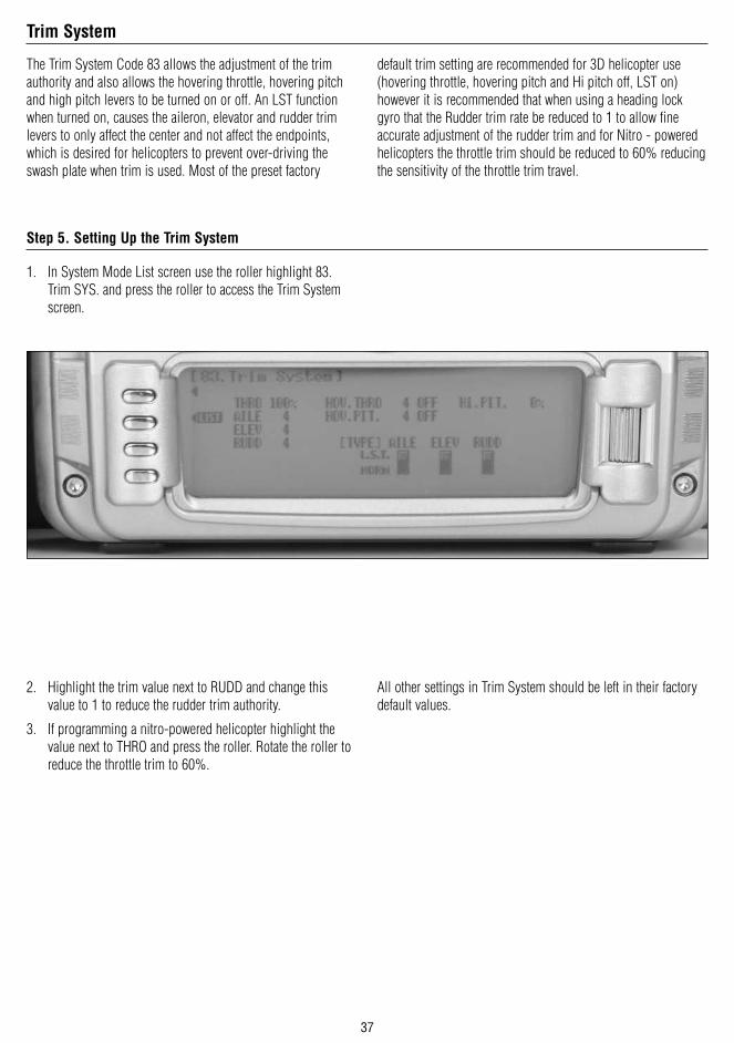
The Trim System Code 83 allows the adjustment of the trim authority and also allows the hovering throttle, hovering pitch and high pitch levers to be turned on or off. An LST function when turned on, causes the aileron, elevator and rudder trim levers to only affect the center and not affect the endpoints, which is desired for helicopters to prevent over-driving the swash plate when trim is used. Most of the preset factory
default trim setting are recommended for 3D helicopter use (hovering throttle, hovering pitch and Hi pitch off, LST on) however it is recommended that when using a heading lock gyro that the Rudder trim rate be reduced to 1 to allow fine accurate adjustment of the rudder trim and for Nitro - powered helicopters the throttle trim should be reduced to 60% reducing the sensitivity of the throttle trim travel.
1. In System Mode List screen use the roller highlight 83. Trim SYS. and press the roller to access the Trim System screen.
2. Highlight the trim value next to RUDD and change this value to 1 to reduce the rudder trim authority.
3. If programming a nitro-powered helicopter highlight the value next to THRO and press the roller. Rotate the roller to reduce the throttle trim to 60%.
All other settings in Trim System should be left in their factory default values.
Step 5. Setting Up the Trim System
Trim System

38
1. Press and hold the ENT button while turning on the power switch to enter the System Mode List screen.
2. Using the roller highlight 17. DeviceSEL and press the roller to access the Device Select screen.
3. Rotate the roller to highlight INH next to Aux2 then press the roller. The available functions will appear.
4. Rotate the roller to highlight GOV then press the roller to activate the governor program and assign it to the Aux 2
All other factory default settings in Device Select are recommended for your first flights.
Step 6. Activating the Governor System

39
2. Rotate the roller and highlight 1servo then press the roller to access the 6 different swash plate types.
1. In System Mode List screen use the roller highlight 34. Swash TYP and press the roller to access the Swash Type screen.
3. Rotate the roller to select the desired swash plate type normally 3 servo 120* (see your helicopters instructions if you‘re not sure) and press the roller to program the selected swash plate type.
Step 7. Selecting a Swash plate Type

40
1. With the system installed in the helicopter, insert the bind plug in the bind receptacle.
2. Turn on the receiver switch. Note that the LED’s on all receivers should be flashing indicating that the receiver is ready to bind.
3. Establish the desired fail-safe stick positions: normally low throttle and aileron, elevator and rudder at neutral.
4. Press and hold the bind button on the back of the transmitter while turning on the power switch. Within a few seconds the system should connect. The LED’s on the receivers should go solid, indicating the system has connected.
5. Remove the bind plug and store it in a convenient place.
6. After you’ve programmed your model, it’s important to rebind the system so the true low throttle and neutral control surface positions are programmed.
Note: To bind a helicopter with an electronic speed controller that powers the receiver through the throttle channel (BEC), insert the bind plug into the battery port and proceed to Step #2.
1. In Function List screen use the roller to highlight 11. REV SW and press the roller to access the Reverse switch screen.
2. Rotate the roller to highlight the desired channel that you wish to reverse and press the roller to reverse that channel. Repeat this for all channels.
Note: Swash plate mixing is unique in that the individual servos are reversed and synchronized using the servo reversing function, however, the overall functional travel direction is established using the Swash Mix screen code 65. It’s necessary to first program the reversing switches such that the swash plate tilts right and left with aileron input, the swash plate tilts fore and aft with elevator input, and the swash plate raises and lowers when pitch changes are made. The overall direction of aileron, elevator and pitch will likely be reversed (right aileron may give left swash plate travel), however, they will be corrected in the following step Swash Mix code 65.
Step 8. Binding
Step 9. Servo Reversing
41
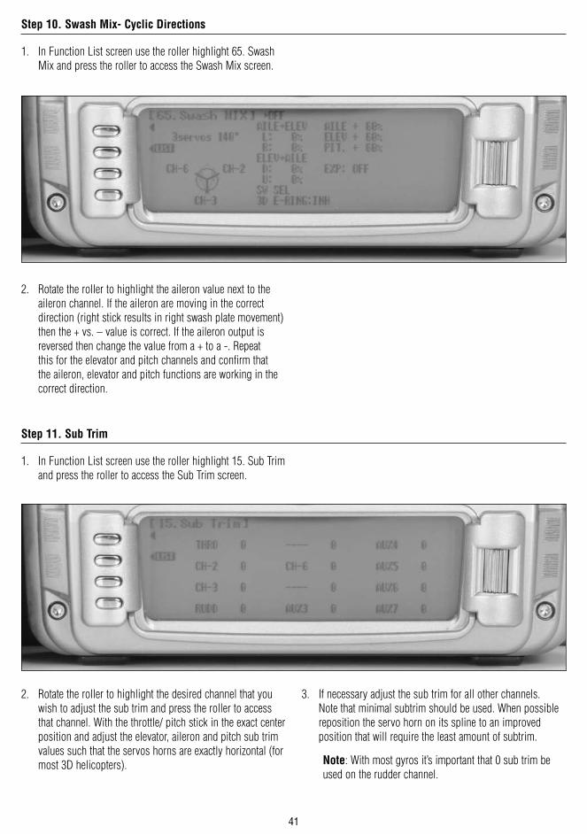
1. In Function List screen use the roller highlight 65. Swash Mix and press the roller to access the Swash Mix screen.
2. Rotate the roller to highlight the aileron value next to the aileron channel. If the aileron are moving in the correct direction (right stick results in right swash plate movement) then the + vs. – value is correct. If the aileron output is reversed then change the value from a + to a -. Repeat this for the elevator and pitch channels and confirm that the aileron, elevator and pitch functions are working in the correct direction.
1. In Function List screen use the roller highlight 15. Sub Trim and press the roller to access the Sub Trim screen.
2. Rotate the roller to highlight the desired channel that you wish to adjust the sub trim and press the roller to access that channel. With the throttle/ pitch stick in the exact center position and adjust the elevator, aileron and pitch sub trim values such that the servos horns are exactly horizontal (for most 3D helicopters).
3. If necessary adjust the sub trim for all other channels. Note that minimal subtrim should be used. When possible reposition the servo horn on its spline to an improved position that will require the least amount of subtrim.
Note: With most gyros it’s important that 0 sub trim be used on the rudder channel.
Step 11. Sub Trim
Step 10. Swash Mix- Cyclic Directions

42
1. In Function List screen use the roller to highlight 65. Swash Mix and press the roller to access the Swash Mix screen.
2. Rotate the roller to highlight the aileron value next to the aileron channel. Deflect the aileron stick fully and increase or decrease the Aileron value until just before the swash plate binds. Do the same for elevator and pitch.
Note: Most 3D helicopters are set up to give maximum swash plate pitch and cyclic travel. If less travel is desired reduce these values.
3. Activate the 3D E-RING by highlighting INH next to 3D E-RING and press the roll to select ACT. Note: The 3D E-ring prevents the servos from over - traveling when full aileron and elevator inputs are given simultaneously. This prevents the swash plate from binding when combined high cyclic rates are input.
4. Activate the swash plate EXPO by highlighting OFF next to EXP: and press the roller to select on. Swash plate EXPO is highly recommended, as this function compensates for the non-linear inaccuracies when the cyclic servo are at the extremes of travel.
1. In Function List screen use the roller to highlight 12. TRVL adjust and press the roller to access the Travel adjust screen.
2. Rotate the roller to highlight the desired channel that you wish to adjust the travel adjust and press the roller to access that channel. Move the corresponding stick or switch in the desired direction to highlight the value for that direction then rotate the roller to adjust the travel adjust value for that direction. Note: For 3D helicopters normally all channels except for the throttle and rudder are left at 100%.
Step 12. Swash Mix- Adjusting Cyclic and Pitch Travel, Activating the E-Ring and EXPO Functions
Step 13. Travel Adjust

43
Many 3D pilots choose to use the same rates for all flight modes and conditions so the response rate is always the same no matter what maneuver or flight mode is selected. Some pilots prefer to use exponential to soften the response rate around neutral, especially on rudder, finding this is helpful in giving more precise control with high response rate helicopters.
1. In Function List screen use the roller to highlight 13. D/R & EXP and press the roller to access the Dual Rate and Expo screen.
2. Rotate the roller to highlight the channel in the upper left of the screen and press the roller. Select AILE, ELEV or RUDD by pressing the roller.
3. Rotate the roller to highlight the desired D/R or EXP value. Note the positions (POS0, POS1, POS2) are activated via the corresponding D/R switch. Typically for 3D flight the D/R value for all channels is left at 100%, The rudder Expo for the JR G770 3D gyro is adjusted to 50% and a good starting point for the aileron and elevator Expo values is 20%.
Dual Rate and Exponential
Step 14. Adjusting Exponential Values

44
1. In Function Mode List screen use the roller highlight 16. THRO Hold and press the roller to access the Throttle hold screen.
2. Rotate the roller and highlight INH then press the roller to access the throttle hold screen and activated throttle hold.
3. Rotate the roller to select the HOLD Pos. then press the roller. Rotate the roller to program the throttle hold position. A value of +8 will program a throttle hold servo position that is in the same position when the throttle stick is in the low position and the trim is in the middle.
Step 15. Activating Throttle Hold

45
1. In Function Mode List screen use the roller to highlight 18. THRO CURV and press the roller to access the all servos hold screen. Press YES or NO to access the Throttle Curve screen.
2. Move the flight mode switch to the desired flight mode that you wish to adjust the throttle curve (normal, stunt 1 or stunt 2).
3. Rotate the roller to highlight the desired point that you wish to change (L, 1 or H) then press the roller to access that point.
4. Rotate the roller to adjust to throttle curve at the selected point. Repeat this process for all flight modes by moving the flight mode switch in the desired position. Additional points can be added by moving the throttle stick to the desired area of the curve until STOR appears on the lower left corner of the screen. Pressing the STOR button will then add an additional point to the curve at this location, which can then be adjusted as mentioned above.
1. In Function Mode List screen use the roller to highlight 68. PIT. CURV and press the roller to access the all servos hold screen. Press YES or NO to access the Pitch Curve screen.
2. Move the flight mode/ hold switch to the desired flight mode that you wish to adjust the pitch curve (normal, stunt 1, stunt 2 or hold).
3. Rotate the roller to highlight the desired point that you wish to change (L, 1 or H) then press the roller to access that point.
4. Rotate the roller to adjust to pitch curve at the selected point. Repeat this process for all flight modes by moving the flight mode/ hold switch in the desired position. Additional points can be added by moving the throttle stick to the desired area of the curve until STOR appears on the lower left corner of the screen. Pressing the STOR button will then add an additional point to the curve at this location, which can then be adjusted as mentioned above.
Step 17. Programming Pitch Curves
Step 16. Programming Throttle Curves

46
1. In Function Mode List screen use the roller highlight 44. Gyro SENS and press the roller to access the Gyro Sensor screen.
2. Rotate the roller to highlight Manual and press to access the available switches that the gyro gain can be assigned to. Select FMOD SW to assign the gyro gain to the flight mode switch.
3. Rotate the roller to highlight NORMAL then press the roller to program tail lock settings for the gain values. (if using a tail lock gyro)
4. Select the desired gain value then press the roller to access the value. Rotate the roller to program the desired gain value. Note that when T. LOCK is selected the gain values represent the true gain % value (rather than 50% being off).
5. Adjust the gain values for all Positions. Note the gain value will automatically be selected in each flight mode.
Note: The Governor must be assigned to a channel in device select to access the Governor function. See Step 6 above.
1. In Function Mode List screen use the roller to highlight 45. Governor and press the roller to access the Governor screen.
2. Rotate the roller to highlight the desired flight mode then press the roller to access governor value.
3. Rotate the roller to select the desired governor value for that flight mode. Note the adjustment is from –125 to +125 and the output correlates to the travel adjust. Using a rev max Governor, 0% turns off the governor while anything above +5% or below –5% activates the governor and sets the limiting rpm . Typically 85 to 90% is used to limit the rpm to approximately 2000, depending on the helicopter‘s gear ratio.
4. Repeat governor adjustments for all flight modes .
Step 18. Programming the Gyro Function
Step 19. Programming The Governor Function

47
1. In System Mode List screen use the roller to highlight 91. STK PosSW and press the roller to access the Stick Switch Position screen.
2. Rotate the roller and highlight SPS0: INH and press the roller to access the available stick position channels.
3. Rotate the roller to highlight THRO then press the roller to access the Throttle stick position option screen.
4. Rotate the roller to highlight POS then press the roller to access the Throttle stick position value. Rotate the roller to select a L85 value (low throttle 85%) then press the roller to program accept that value SPS screen w/ 85% in POS
5. Press the LIST button to exit the SPS screen and return to the System Mode List.
Step 20. Programing a Timer to Start with Throttle Up

48
1. In Function Mode List screen use the roller to highlight 87. Timer and then press the roller to access the Timer screen.
2. Rotate the roller and highlight Timer1:INH and press the roller to access the available timer types. (DOWN-T, STOP W or INH)
3. Rotate the roller to highlight DOWN-T then press the roller to access timer options.
4. Rotate the roller to highlight START TIM KEY then press the roller to access the switch that will activate the timer. Rotate the roller to select SPS0 then press the roller to program accept that value SPS0 Switch position.
5. Rotate the roller to highlight Set Time then press the roller to access the pre-programmed time. Rotate the roller to select the desired down time (typical flight time) then press the roller to program accept that value.
6. Rotate the roller to highlight One Time: OFF then press the roller to turn this function on.
Note: The one time function will turn the timer on when the throttle is raised and remain on even when the throttle is reduced to idle.
7. Press the LIST button to exit the SPS screen and return to the System Mode List.
8. The timer will now start when the throttle is advanced.
9. To reset the timer from the main screen, highlight Down1 and press the clear button.
Timer Programming

49
Programming a Full Function Sailplane
Following is a step-by-step programming guide for a 6-channel full function sailplane that will familiarize you with a typical setup procedure. We recommend following this setup guide during your first attempts at programming, as it will familiarize you with the available functions and how flight modes operate. Later you can customize this setup, adding more flight modes, changing function locations, etc. to meet your specific needs and preferences.
The following setup utilizes three flight modes (Launch, Cruise and Land), which are selected using the 3-position Elevator Dual Rate switch on the upper left face of the transmitter. Trailing edge camber adjustment will be assigned to the right side lever in the launch and cruise mode. Butterfly (landing flaps) will be assigned to the spoiler stick (throttle stick) to be active in all flight modes. This is the setup many pilots use and this program offers a great base for sailplane pilots to develop their own setups from.
Camber Adjustment
Flight Modes–Launch, Cruise and Land
Spoiler Stick–Crow (Landing
Flaps)

50
Note on Installing Flap Servos: Typical flap geometry requires that the servo arms be significantly offset to provide adequate down flap throw. This issue exists because flaps typically have a large travel down (80 to 90 degrees) but very little up travel (less than 15 degrees). To achieve proper flap travel, it is necessary that the right flap sub trim is set at 225 down and the left flap sub trim is set at 225 up as a starting point. Then when installing the flap
servo arms, be sure the spoiler stick is in the up position and camber lever is in the middle position. Install the flap servo horns such that they are angled approximately 30 degrees toward the trailing edge (if the flaps have the control horn on the bottom of the flap) or 30 degrees toward the leading edge (if the flap control horn is on top of the flap) then adjust the flap linkage such that the flaps are level. See Sub Trim below for more details.
30°
30°
B OTTOM C ONTR OL HOR N
TOP C ONTR OL HOR N

51
Channel Assignment
Important: In glider mode, the channel assignment (servo lead positions in the receiver) of the 12X reassigns servo outputs to optimized positions. This new channel assignment has two important advantages:
• It allows a 6-channel receiver to be used to control the 6 functions commonly found on full function 6 - channel sailplanes or a 7 - channel receiver to be used for 7 - channel electric sailplanes.
• It locates commonly mixed channels, like right and left ailerons, right and left flaps, rudder and elevator for (V-tail), next to each other in the data stream, minimizing synchronizing delay issues.
Use the following to locate the correct locations for the servos:
Left Flap 6 Flap/ Aux. 1
Right Flap 5 Gear
Rudder 4 Rudder
Elevator 3 Elevator
Right Aileron 2 Aileron
Left Aileron 1 Throttle
Step 1. Servo Assignment

52
5. Press and hold the ENT button while turning on the power switch to enter the System Mode List screen.
6. Using the roller highlight 84. Model SEL and press the roller to access the Model Select screen. Rotate the roller to highlight MODEL then press the roller. The following screen will appear.
7. Rotate the roller to highlight the desired model memory (1 thru 50) then press the roller to select the highlighted model memory.
Note: It is recommended that an unused model memory be selected.
Step 2. Selecting a Model Memory

53
3. In System Mode List screen use the to roller highlight 89. Type SEL and press the roller to access the Type Select screen.
4. Rotate the roller to highlight GLID then press the roller to enter the GLID program.
Note: All programming in the selected model memory will be reset to factory defaults.
3. In System Mode List screen use the roller highlight 28 MDL. Reset. and press the roller to access the Model Reset screen.
4. Press the REST button then press YES to reset the model memory to Factory Default settings.
Note: All programming in the selected model memory will be reset to factory defaults.
Step 3. Selecting the Model Type (GLID)
Step 4. Resetting the Model Memory

54
5. In System Mode List screen use the roller highlight 81. MDL Name and press the roller to access the Model Name screen.
6. Rotate the roller to select the desired position to place a letter or number (up to 16 characters) and press the roller to access the Character screen.
7. Rotate the roller to select the desired number or letter and press the roller to transfer that character to the selected position.
8. Repeat until naming is complete. Press LIST to return to the System mode list.
Step 5. Naming the Model

55
1. In the System Menu list, rotate the Selector until 83. TRIM SYS is highlighted. Depress the Selector to access the TRIM SYSTEM menu.
2. Rotate the Selector to highlight SPOI 100% and press the Selector to access the spoiler trim value.
3. Rotate the Selector until a 0% is shown. This will turn off the spoiler trim, preventing any unwanted interaction with the spoiler trim and the spoiler stick. Depressing the Selector will store the desired 0% value in the model memory
4. Rotate the Selector to highlight FLAP and press the Selector to access the Flap trim value.
5. Rotate the Selector until a 0 is shown. This will turn off the Flap trim,
6. Repeat this process to turn off the Flaperon (FPRN) trim.
7. Press the LIST button to return to the System Mode screen.
1. In the SYSTEM M. list, rotate the Selector until 17. DeviceSEL is highlighted. Depress the Selector to access the Device select menu. Initially we are going to activate three of the available five flight modes (Launch, Cruise and Land).
2. Rotate the Selector to highlight LAUNCH and press the Selector to access the available switches that the flight mode can be assigned to. For our purpose, assign the LAUN flight mode to ELEV D/R SW (elevator dual rate switch). Later you can change the flight mode to the position that best suits your needs.
3. Rotate the Selector until ELEV D/R SW is highlighted and press the Selector to store the desired left 3-position switch. Press the LIST button to return to the System Mode screen.
Step 6. Turning Off the Spoiler Stick Trim and the Flap and Flaperon Trims
Step 7. Establishing Flight Modes

56
1. In the SYSTEM M. list, rotate the Selector until 17. DeviceSEL is highlighted. Depress the Selector to access the Device select menu.
2. It’s necessary to turn off unused channels, making them available as flap channels, etc. Rotate the Selector to highlight ACT next to aux 2 channel and press the Selector to inhibit the aux. 2 channel.
3. Repeat this for Aux. 3 thru aux. 7 channels turning off these channels. Press the LIST button to return to the System Mode screen. Press the LIST button to return to the System Mode screen.
Note: The flap lever should remain active.
1. In the SYSTEM M. list, rotate the Selector until 22. Wing Type is highlighted. Depress the Selector to access the Wing Type menu.
2. If your sailplane has a V-tail, rotate the Selector to highlight V-tail and press the Selector to select ACT.
3. Rotate the Selector to access the DUAL FLAP function and press the Selector to access dual flap if your sailplane has individual servos for each flap. Select MOTO (gear channel 5) as the flap channel. Press the LIST button to return to the System Mode screen.
Step 8. Turning off Unused Channels
Step 9. Wing and Tail Type Select

57
1. With the system installed in the sailplane, insert the bind plug in the bind receptacle.
2. Turn on the receiver switch. Note that the LED’s on all receivers should be flashing indicating that the receiver is ready to bind.
3. Establish the desired fail-safe stick positions: normally aileron, elevator, flaps and rudder at neutral (motor off if equipped) .
4. Remove the bind plug. This will cause the system to go into preset failsafe such that if signal is lost all channels will acquire their preset failsafe positions.
Note: Preset failsafe is only available on 9 - channel and greater receivers.
5. Press and hold the bind button on the back of the transmitter while turning on the power switch. Within a few seconds the system should connect. The LED’s on the receivers should go solid, indicating the system has connected.
6. Remove the bind plug and store it in a convenient place.
7. After you’ve programmed your sailplane, it’s important to rebind the system so the true neutral control surface positions are programmed.
To enter the Function list, turn on the transmitter and then press the LIST button on the transmitter. The following screen will appear.
1. In Function List screen use the roller to highlight 11. REV. SW and press the roller to access the Reverse switch screen.
2. Rotate the roller to highlight the desired channel that you wish to reverse and press the roller to reverse that channel.
3. Repeat this for all channels. Press the LIST button to return to the Function Mode screen.
Step 10. Binding
Step 11. Entering Function List
Step 12. Servo Reversing

58
1. In FUNC.LIST rotate the Selector until 15. Sub Trim is highlighted. Press the Selector to access the Sub Trim menu.
2. Rotate the Selector to highlight the desired channel then press the Selector to change the sub trim value of the selected channel. Sub trim all functions so that they are in the neutral position (see flap note below). Press the LIST button to return to the Function Mode screen.
Note: Typical flap geometry requires that the sub trim be significantly offset to provide adequate down flap throw. This issue exists because flaps typically have a large travel down (80 to 90 degrees) but very little travel up (less than 15 degrees). To achieve proper flap travel, it is necessary that the right flap sub trim be set at 225 down and the left flap sub trim be set at 225 up as a starting point. Then, when attaching the flap servo arms, be sure the spoiler stick is in the up position and camber lever is in the middle position. Install the flap servo horns such that they are angled approximately 30% toward the trailing edge, then adjust the flap linkage such that the flaps are level.
Step 13. Sub Trim

59
1. In Function List screen use the roller to highlight 12. TRVL adjust and press the roller to access the Travel adjust screen.
2. Rotate the roller to highlight the desired channel that you wish to adjust the travel adjust and press the roller to access that channel. Move the corresponding stick or switch in the desired direction to highlight the value for that direction then rotate the roller to adjust the travel adjust value for that direction.
3. Set the travel adjust for all functions except flaps at this time. Press the LIST button to return to the Function Mode screen.
This screen adjusts the amount and direction that the flaps, flaperons, elevator and spoilers (if equipped) are deployed using the Spoiler stick.1. In FUNC.LIST rotate the Selector until 71. Brake SYS is
highlighted. Press the Selector to access the Brake system menu. Note the default setting at the lower left of the screen is offset at +100%. (SPOI Pos. 100) With this setting, the flap’s neutral position (trailing edge level) occurs when the spoiler stick is in the full up position.
2. Rotate the Selector to highlight SW select and press the Selector to access the available switches. Be sure all switches in this screen are set at 0. This is necessary to allow the landing system function to always be on. Later a switch can be selected allowing differ values or for the brake system or to be turned off (Pos0 or Pos1).
3. Rotate the Selector to highlight FPRN 0 then depress the Selector to access the spoiler-to-flaperon value. Move the spoiler stick to the full down position and adjust the flaperon position by rotating the Selector until the desired flaperon position is achieved (normally a few degrees of up ailerons). Press the Selector to store this flaperon value.
4. Rotate the Selector to highlight FLAP 0 then depress the Selector to access the spoiler-to-flap value. Move the spoiler stick to the full down position and adjust the flap position by rotating the Selector until the desired down flap position is achieved (normally 80 degrees down). Press the Selector to store the flap value.
Step 14. Travel Adjust
Step 15. Brake System (Butterfly/ Landing Flaps)

60
On most sailplanes, deploying flaps causes the aircraft to pitch up. This pitching is non-linear and typically the airplane pitches up dramatically the first 25% of flap travel but becomes less dramatic during the 25% through 50% range, and very little additional up pitching occurs from 75 to 100% flaps. The 12X incorporates a Brake to Elevator curve mix that mixes the spoiler stick (landing flaps) to the elevator with up to 7 programmable points.
1. In the brake system menu (code71) rotate the Selector to access the BRAKE-ELEV function POS0. This function allows a curve mix for elevator compensation with up to 7 points on the curve to be stores.
2. Select the desired points 0 thru 6 and depress the Selector to access the value for each point and with the spoiler stick in the corresponding position, adjust the value until the desired elevator position is achieved.
3. Repeat this for all of the desired points. Press the LIST button to return to the Function Mode screen.
Step 16. Brake to Elevator (Spoiler to Elevator Curve Mix)

61
Thus far we have established the foundational programming that will be common to all flight modes. Now we will focus on the specifics of setting up each individual flight mode.
We will be individually programming the following parameters for each of the selected flight modes
(Launch, Cruise, Land).• Dual and Exponential rates for Aileron, Elevator and Rudder
• Setting preset positions for the Flaps, Flaperons and Elevator
• Elevator-to-Flap Mixes
• Aileron-to-Flap Mixes
• Aileron Differential
• Camber Adjustment
• Aileron-to-Rudder Mixes
In Step #7 above, Establishing Flight Modes, flight modes were programmed to operate from the Elevator D/R 3-position switch. To select Launch mode, the Elevator D/R 3-position switch must be moved in the down position. In the main (info) screen LAUNCH will appear in the upper left portion of the display when Launch mode is selected. When making programming changes/adjustments in Launch mode, this 3-position switch must remain in the lower position during the process to allow the results of those adjustments to be seen on the model.
Setting Up Flight Modes
Step 17. Launch Mode Setup

62
The 12X offers a sophisticated Camber System program that allows easy preset positions for each flap and each aileron (flaperon). Flight mode presets are automatically selected via the flight mode switch and are adjusted in the Camber System.
Note: Elevator preset positions are active in each flight mode using the elevator trim.
1. In FUNC.LIST rotate the Selector until 25. CAMB SYS. is highlighted. Press the Selector to access the Camber System menu.
2. Rotate the Selector to highlight LAIL (left aileron) next to LAUNCH and press the Selector to access the value. With the flight mode switch in the Launch mode rotate the roller to adjust the preset position of the left aileron in launch mode.
3. Repeat the process for setting up the launch presets for the right aileron, left flap and right flap.
Note: Elevator presets are adjusted and selected using the elevator trim. Each flight mode has its own stored trim position such that when the flight mode is selected, the elevator trim is recalled and active.
Step 18. Camber System (Launch Pre-sets)

63
1. In FUNC.LIST, rotate the Selector until D/R & EXP is highlighted. Press the Selector to access the Dual Rate and Exponential menu.
2. Rotate the Selector to highlight the channel (aile, elev or rudd) then press the Selector to select the desired channel that you wish to adjust the dual and expo rates for. Rotate to select then press the Selector to store the desired channel.
3. Note that five D/R and EXPO positions (values) are available (Pos0, 1, 2, 3 and 4). Under AUTO on the right of the screen, rotate the Selector until LAUN is highlighted and press the Selector. Select Pos0 as the active position for the launch mode by rotating the Selector and then pressing the Selector when Pos0 is highlighted. This will automatically access dual rate and expo values that are programmed into position 0 whenever the launch mode is selected.
4. Now rotate the Selector to Pos0 and depress the Selector to highlight the D/R values. Rotating the Selector changes these values. Displacing the aileron stick right or left allows the dual rate to be independently adjusted in each direction. Depress the Selector to store the desired D/R values.
5. Rotate the Selector to the EXP Pos0 values and adjust these values in the same manor pressing the Selector to store the desired value.
6. Now return to the selected channel and do the same thing for the two remaining channels. Press the LIST button to return to the Function Mode screen.
Step 19. Dual Rate and Exponential

64
Many pilots prefer to have variable camber adjustment during launch. This enables adjustments to be made at the last minute or even during launch, based on wind and winch conditions.
Important: The flaperon and elevator values in the Flaperon Mix 21. menu are based on a percentage of the programmed flap rate. The flap rates are defaulted to 0% from the factory, so Flap to Flaperon and Flap to Elevator mix values have no effect until the flap rate values are set. Because of this, it’s mandatory to first adjust the flap rates before adjusting the flaperon and elevator mixes. Also remember that changing the flap rate values also affects the flaperon and elevator flap mixes.
1. In FUNC.LIST rotate the Selector until 69. FLAP Rate is highlighted. Press the Selector to access the Flap Rate menu.
2 Rotate the Selector to highlight the Up or Down values next to LAUNCH. Adjust the up and down values such that when the flap lever is actuated via the flap lever (right lever) and the elevator D/R switch is in the Launch mode, the values obtain the desired flap positions. Press the LIST button to return to the Function Mode screen.
Step 20. Flap Rate

65
The Flaperon mix function allows three different mixes to be programmed and selected in each flight mode. This function mixes the flap lever (right lever) to the Flaperons, Elevator and mixes aileron to flaps.1. In FUNC.LIST rotate the Selector until 21. Flaprn MX is
highlighted. Press the Selector to access the Flaperon Mix menu.
2. Rotate the Selector to highlight Flap- FPRN. mix under Launch. Adjust the up and down values such that when the flaps are actuated via the flap lever (right lever) and the elevator alignment D/R switch is in the launch position, the desired up and down flaperon positions are achieved.
3. Rotate the Selector to highlight FLAP- ELEV mix under Launch. Adjust the up and down values such that when the flaps are actuated via the flap lever (right lever) and the elevator D/R switch is in the launch position, the desired up and down elevator positions are achieved.
Aileron to flap mix gives added roll response by mixing ailerons to flaps such that the entire trailing edge functions as an aileron.
1. Rotate the Selector to highlight AILE -FLAP mix under Launch. Adjust the right and left values such that when the aileron are displaced via the aileron stick and the elevator D/R switch is in the launch position, the desired right and left flap positions are achieved.
Step 21. Flaperon Mixes (Flap to Flaperon/ Flap to Elevator/ Aileron to Flap)

66
1. In FUNC.LIST rotate the Selector until 32. DIFFEREN is highlighted. Press the Selector to access the Aileron differential menu.
2. Rotate the Selector to highlight the launch aileron value then press the Selector to access that value.
3. With the flight mode switch in the lower launch mode, give a full right aileron command and rotate the Selector to achieve the desired aileron differential for launch. Pressing the Selector will store the value.
4. Now rotate the Selector to highlight the launch flap value and adjust it to the desired position. Press the LIST button to return to the Function Mode screen.
1. In FUNC.LIST rotate the Selector until 62. AILE to RUDD is highlighted. Press the Selector to access the Aileron-to-Rudder mix menu.
2. Rotate the Selector to highlight the launch left value then press the Selector to access that value. With the flight mode switch in the lower launch mode, give a full left aileron command and rotate the Selector to achieve the desired left rudder throw. Pressing the Selector will store the value.
3. Now rotate the Selector to highlight the launch right value and adjust it to the desired position. Press the LIST button to return to the Function Mode screen.
Step 22. Aileron Differential
Step 23. Aileron-to-Rudder Mix

67
In Step #7, Establishing Flight Modes, flight modes were programmed to operate from the left front 3-position Dual Rate switch. To select Cruise mode, the left 3-position switch must be moved to the middle position. In the main (info) screen CRUISE will appear in the upper left portion of the display when Cruise mode is selected. When making programming changes/adjustments in Cruise mode, this 3-position switch must remain in the middle position during the process to allow the results of those adjustments to be seen on the model.
This function is normally not used in the cruise mode, however, it is available.
1. In FUNC.LIST, rotate the Selector until 13. D/R & EXP is highlighted. Press the Selector to access the Dual Rate and Exponential menu.
2. Rotate the Selector to highlight the channel (aile, elev or rudd) then press the Selector to select the desired channel that you wish to adjust the dual and expo rates for.
3. Rotate to select to adjust the desired value then press the Selector to store the desired channel. Note that five D/R and EXPO positions (values) are available (Pos0, 1, 2, 3 and 4).
4. Under AUTO on the right of the screen, rotate the Selector until CRUI is highlighted and press the Selector. Select Pos1 as the active position for the cruise mode by rotating the Selector and then pressing the Selector when Pos1 is highlighted. This will automatically access dual rate and expo values that are programmed into position 1 whenever the cruise mode is selected. Now rotate the Selector to Pos1 and depress the Selector to highlight the D/R values. Rotating the Selector changes these values. Displacing the aileron stick right or left allows the dual rate to be independently adjusted in each direction. Depress the Selector to store the desired D/R values. Rotate the Selector to the EXP Pos1 values and adjust these values in the same manor, pressing the Selector to store the desired value.
Now go back to channel and do the same thing for the two remaining channels. Press the LIST button to return to the Function Mode screen.
Setting Up Cruise Mode
Step 24. Camber System (Cruise Pre-sets)
Step 25. Dual Rate and Exponential

68
1. In Function Mode list, rotate the Selector until 63. ELEV to FLAP is highlighted. Press the Selector to access the Elevator-to-Flap mix menu.
2. Note that the elevator-to-flap values can be independently adjusted up and down. Also the offset (the stick position where the mixing changes from up to down) can be adjusted. This offset allows the programming of snap-flaps, a common sailplane function that gives greater full up elevator pitch authority for tighter turns. With snap-flaps, no flap mixing occurs during small to medium up elevator inputs, but at about 80% up elevator, the flaps are mixed to give down flaps, causing greater up pitch authority.
3. Rotate the Selector to highlight the CRUISE (cruise mode) values depress the Selector to select that value.
4. If you choose to program snap-flaps, rotate the Selector until the Offset is highlighted and depress the Selector to access this value. A 0 value locates the offset position when the elevator is centered. The adjustment range is -200 to +200. Negative values move the offset in the up elevator direction. Set a value of –100 to start, as this will locate the offset at 80% up elevator. Press the Selector to store this offset value.
5. With the 3-position switch in the middle (cruise) position, give a full up elevator command and hold while adjusting the Cruise up value until the desired down flap position is achieved. Press the LIST button to return to the Function Mode screen.
5. In FUNC.LIST rotate the Selector until 32.DIFFEREN. is highlighted. Press the Selector to access the Aileron differential menu.
6. Rotate the Selector to highlight the CRUISE aileron value then press the Selector to access that value.
7. With the flight mode switch in the middle Cruise mode, give a full right aileron command and rotate the Selector to achieve the desired aileron differential for launch. Pressing the Selector will store the value.
8. Now rotate the Selector to highlight the launch flap value and adjust it to the desired position. Press the LIST button to return to the Function Mode screen.
Step 27. Aileron Differential
Step 26. Elevator-to-Flap Mix

69
The Flaperon mix function allows three different mixes to be programmed and selected in each flight mode. This function mixes the flap lever (right lever) to the Flaperons, Elevator and mixes aileron to flaps.1. In FUNC.LIST rotate the Selector until 21. Flaprn MX is
highlighted. Press the Selector to access the Flaperon Mix menu.
2. Rotate the Selector to highlight Flap- FPRN. mix under Launch. Adjust the up and down values such that when the flaps are actuated via the flap lever (right lever) and the elevator alignment should be the same throughout D/R switch is in the Cruise position, the desired up and down flaperon positions are achieved.
3. Rotate the Selector to highlight FLAP- ELEV mix under CRUISE. Adjust the up and down values such that when the flaps are actuated via the flap lever (right lever) and the elevator D/R switch is in the launch position, the desired up and down elevator positions are achieved.
Aileron to flap mix gives added roll response by mixing ailerons to flaps such that the entire trailing edge functions as an aileron.
4. Rotate the Selector to highlight AILE -FLAP mix under Cruise. Adjust the right and left values such that when the aileron are displaced via the aileron stick and the elevator D/R switch is in the Cruise position, the desired right and left flap positions are achieved.
Step 28. Flaperon Mixes (Flap to Flaperon/ Flap to Elevator/ Aileron to Flap)

70
Most pilots prefer to have variable camber adjustment during Cruise. This enables adjustments to be made based on wind and lift conditions.
Important: The flaperon and elevator values in the Flaperon Mix 21. menu are based on a percentage of the programmed flap rate. The flap rates are defaulted to 0% from the factory, so Flap to Flaperon and Flap to Elevator mix values have no effect until the flap rate values are set. Because of this, it’s mandatory to first adjust the flap rates before adjusting the flaperon and elevator mixes. Also remember that changing the flap rate values also affects the flaperon and elevator flap mixes.
1. In FUNC.LIST rotate the Selector until 69. FLAP Rate is highlighted. Press the Selector to access the Flap Rate menu.
2. Rotate the Selector to highlight the Up or Down values next to CRUISE. Adjust the up and down values such that when the flap lever is actuated via the flap lever (right lever) and the elevator D/R switch is in the CRUISE mode adjust the values to obtain the desired flap positions. Press the LIST button to return to the Function Mode screen.
3. In FUNC.LIST rotate the Selector until 62. AILE to RUDD is highlighted. Press the Selector to access the Aileron-to-Rudder mix menu.
4. Rotate the Selector to highlight the CRUISE left value then press the Selector to access that value. With the flight mode switch in the middle Cruise mode, give a full left aileron command and rotate the Selector to achieve the desired left rudder throw. Pressing the Selector will store the value.
5. Now rotate the Selector to highlight the launch right value and adjust it to the desired position. Press the LIST button to return to the Function Mode screen.
Step 29. Flap Rate
Step 30. Aileron-to-Rudder Mix

71
Setting Up Land Mode
In Step #7, Establishing Flight Modes, flight modes were programmed to operate from the left front 3-position switch. To select Land mode, the left 3-position switch must be moved to the up position. In the main (info) screen LAND will appear in the upper portion of the display when Land mode is selected. When making programming changes/adjustments in Land mode, this 3-position switch must remain in the upper position during the process to allow the results of those adjustments to be seen on the model.
The 12X offers a sophisticated Camber System program that allows easy preset positions for each flap and each aileron (flaperon). Flight mode presets are automatically selected via the flight mode switch and are adjusted in the Camber System.
Note: Elevator preset positions are active in each flight mode using the elevator trim.
1. In FUNC.LIST rotate the Selector until 25. CAMB SYS. is highlighted. Press the Selector to access the Camber System menu.
2. Rotate the Selector to highlight LAIL (left aileron) next to LAND and press the Selector to access the value. With the flight mode switch in the LAND mode rotate the roller to adjust the preset position of the left aileron in launch mode.
3. Repeat the process for setting up the launch presets for the right aileron, left flap and right flap.
Note: Elevator presets are adjusted and selected using the elevator trim. Each flight mode has it’s own stored trim position such that when the flight mode is select the elevator trim is recalled and active.
Step 31. Camber System (Land Pre-sets)

72
1. In FUNC.LIST, rotate the Selector until D/R & EXP is highlighted. Press the Selector to access the Dual Rate and Exponential menu.
2. Rotate the Selector to highlight the channel (aile, elev or rudd) then press the Selector to select the desired channel that you wish to adjust the dual and expo rates for. Rotate to select then press the Selector to store the desired channel.
3. Note that five D/R and EXPO positions (values) are available (Pos0, 1, 2, 3 and 4). Under AUTO on the right of the screen, rotate the Selector until LAUN is highlighted and press the Selector. Select Pos0 as the active position for the launch mode by rotating the Selector and then pressing the Selector when Pos0 is highlighted. This will automatically access dual rate and expo values that are programmed into position 0 whenever the launch mode is selected.
4. Now rotate the Selector to Pos0 and depress the Selector to highlight the D/R values. Rotating the Selector changes these values. Displacing the aileron stick right or left allows the dual rate to be independently adjusted in each direction. Depress the Selector to store the desired D/R values.
5. Rotate the Selector to the EXP Pos0 values and adjust these values in the same manor pressing the Selector to store the desired value.
6. Now return to the selected channel and do the same thing for the two remaining channels. Press the LIST button to return to the Function Mode screen.
This function is normally not used in Land mode. It was addressed above in setting up the Cruise mode.
This function is normally not used in Land mode. It was addressed above in setting up the Launch and Cruise modes.
Step 32. Dual Rate and Exponential
Step 33. Elevator-to-Flap Mix
Step 33. Aileron-to-Flap

73
Step 34. Aileron Differential
1. In FUNC.LIST rotate the Selector until 32.DIFFEREN. is highlighted. Press the Selector to access the Aileron differential menu.
2. Rotate the Selector to highlight the LAND aileron value then press the Selector to access that value.
3. With the flight mode switch in the upper Land mode, give a full right aileron command and rotate the Selector to achieve the desired aileron differential for launch. Pressing the Selector will store the value.
4. Now rotate the Selector to highlight the land flap value and adjust it to the desired position. Press the LIST button to return to the Function Mode screen.

74
The Flaperon mix function allows three different mixes to be programmed and selected in each flight mode. This function mixes the flap lever (right lever) to the Flaperons, Elevator and mixes aileron to flaps.1. In FUNC.LIST rotate the Selector until 21. Flaprn MX is
highlighted. Press the Selector to access the Flaperon Mix menu.
2. Rotate the Selector to highlight Flap- FPRN. mix under LAND. Adjust the up and down values such that when the flaps are actuated via the flap lever (right lever) and the elevator D/R switch is in the LAND position, the desired up and down flaperon positions are achieved.
3. Rotate the Selector to highlight FLAP- ELEV mix under LAND. Adjust the up and down values such that when the flaps are actuated via the flap lever (right lever) and the elevator D/R switch is in the launch position, the desired up and down elevator positions are achieved.
Aileron-to-Flap mix gives added roll response by mixing ailerons to flaps such that the entire trailing edge functions as an aileron.
4. Rotate the Selector to highlight AILE -FLAP mix under Cruise. Adjust the right and left values such that when the aileron are displaced via the aileron stick and the elevator D/R switch is in the Cruise position, the desired right and left flap positions are achieved.
Step 35. Flaperon Mixes (Flap to Flaperon/ Flap to Elevator/ Aileron to Flap)

75
Important: The flaperon and elevator values in the Flaperon Mix 21. menu are based on a percentage of the programmed flap rate. The flap rates are defaulted to 0% from the factory, so Flap to Flaperon and Flap to Elevator mix values have no effect until the flap rate values are set. Because of this, it’s mandatory to first adjust the flap rates before adjusting the flaperon and elevator mixes. Also remember that changing the flap rate values also affects the flaperon and elevator flap mixes.
1. In FUNC.LIST rotate the Selector until 69. FLAP Rate is highlighted. Press the Selector to access the Flap Rate menu.
2. Rotate the Selector to highlight the Up or Down values next to LAND. Adjust the up and down values such that when the flap lever is actuated via the flap lever (right lever) and the elevator D/R switch is in the LAND mode adjust the values to obtain the desired flap positions. Press the LIST button to return to the Function Mode screen.
1. In FUNC.LIST rotate the Selector until 62. AILE to RUDD is highlighted. Press the Selector to access the Aileron-to-Rudder mix menu.
2. Rotate the Selector to highlight the LAND left value then press the Selector to access that value. With the flight mode switch in the upper LAND mode, give a full left aileron command and rotate the Selector to achieve the desired left rudder throw. Pressing the Selector will store the value.
3. Now rotate the Selector to highlight the LAND right value and adjust it to the desired position. Press the LIST button to return to the Function Mode screen.
Step 36. Flap Rate
Step 37. Aileron-to-Rudder Mix

76 13568
© 2008 Horizon Hobby, Inc. 4105 Fieldstone Road Champaign, IL 61822
(877) 504.0233 www.horizonhobby.com