applications guide layer off or delete layer to remove from the
TRANSCRIPT
CTE-5202 Analog Electronic Thermostat w/ LCD Display 1 Applications Guide, AN0912A Rev. B
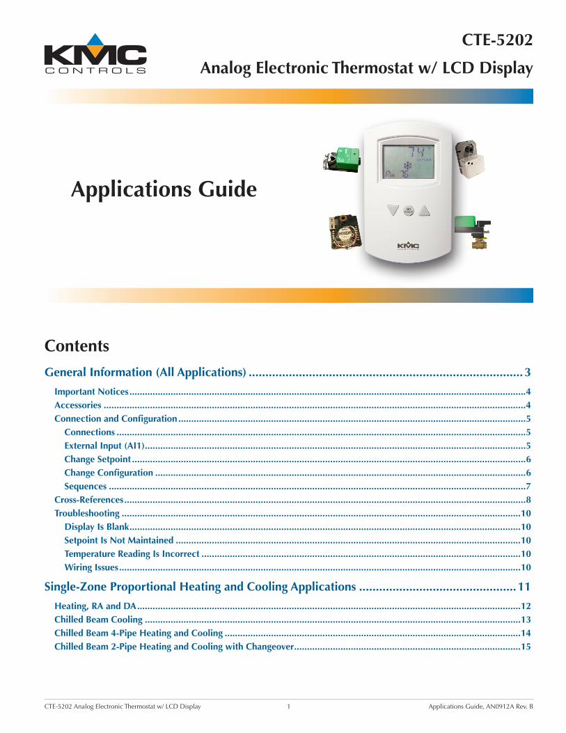
Applications Guide
DRAFTNOTE: Watermark is
on nonwritable DRAFT
Watermark layer. Turn the
layer off or delete layer
to remove from the final
document.
CTE-5202
Analog Electronic Thermostat w/ LCD Display
Contents
General Information (All Applications) ..................................................................................3
Important Notices ..........................................................................................................................................................4Accessories ....................................................................................................................................................................4Connection and Configuration .......................................................................................................................................5
Connections ...............................................................................................................................................................5External Input (AI1) ....................................................................................................................................................5Change Setpoint .........................................................................................................................................................6Change Configuration ................................................................................................................................................6Sequences ..................................................................................................................................................................7
Cross-References ............................................................................................................................................................8Troubleshooting ...........................................................................................................................................................10
Display Is Blank ........................................................................................................................................................10Setpoint Is Not Maintained ......................................................................................................................................10Temperature Reading Is Incorrect ............................................................................................................................10Wiring Issues ............................................................................................................................................................10
Single-Zone Proportional Heating and Cooling Applications ...............................................11
Heating, RA and DA .....................................................................................................................................................12Chilled Beam Cooling ..................................................................................................................................................13Chilled Beam 4-Pipe Heating and Cooling ...................................................................................................................14Chilled Beam 2-Pipe Heating and Cooling with Changeover ........................................................................................15
CTE-5202 Analog Electronic Thermostat w/ LCD Display 2 Applications Guide, AN0912A Rev. B
Pressure Dependent VAV Applications with MEP-4002 ........................................................16
Cooling or Heating .......................................................................................................................................................17Auto and Override (to Fully Closed) ............................................................................................................................18Other Applications .......................................................................................................................................................18
Pressure Independent VAV Applications with CSP-5001/5002 .............................................19
Cooling or Heating .......................................................................................................................................................20Auto and Override (to Fully Closed or Fully Open) ......................................................................................................21Cooling and 3-Stage Reheat .........................................................................................................................................22Cooling with 3-Stage Reheat and Night Setback/Setup ................................................................................................23Cooling with Heating Changeover ...............................................................................................................................24Cooling with Heating Changeover and Electric Reheat ................................................................................................25Cooling with Heating Changeover and Hot Water Reheat ...........................................................................................26Cooling with Hot Water Reheat ...................................................................................................................................27Fan Induction with 2-Stage Electric Heat .....................................................................................................................28Dual Duct, Minimum Air from Cold Duct ....................................................................................................................29
Pressure Independent VAV and CAV Applications with CEP/CSP-4000 Series ......................30
9.1 VDC vs. 24 VAC Power Options .............................................................................................................................31Cooling ........................................................................................................................................................................32Cooling with Morning Warm-Up ..................................................................................................................................33Cooling with 3-Stage Reheat ........................................................................................................................................34Cooling/Heating Changeover .......................................................................................................................................35Cooling with Proportional Hot Water Reheat ...............................................................................................................36Fan Induction with 2-Stage Electric Heat .....................................................................................................................37Damper Tracking (Master/Slave) ..................................................................................................................................38Dual Duct Heating and Cooling VAV ...........................................................................................................................39Dual Duct Heat/Cool Constant Volume with Hot Deck Make-Up ................................................................................40
Barber Colman TP-81xx Thermostats Replacement Applications ..........................................41
TP-8101/8102/8103 Replacement (General) ...............................................................................................................42TP-8101/8102/8103 Replacement with MP-52xx Actuators ........................................................................................43TP-8124/8125 Replacement with One or No MP-52xx Actuators ................................................................................44TP-8124/8125 Replacement with Two MP-52xx Actuators ...........................................................................................45
Index ....................................................................................................................................46

General Information (All Applications) 3 CTE-5202 Applications Guide, AN0912A Rev. B
General Information
(All Applications)
Specifications, design, and operation are subject to change without notice.
This document gives schematics of sample (new and retrofit) applications, cross-references, troubleshoot-ing, and other related information.
For general mounting and connection details, including power connections and input/output connections, see the CTE-5202 Installation Guide.
For specifications and other information, see the CTE-5202 Data Sheet.
The latest support files are always available on the KMC Controls web site (www.kmccontrols.com).
(Shown adjusting the Cooling setpoint— during normal operation, only room temperature is shown in
the upper right of the screen)

General Information (All Applications) 4 CTE-5202 Applications Guide, AN0912A Rev. B
Important NoticesThe KMC logo is a registered trademark of KMC Controls, Inc. All rights reserved. No part of this publication may be reproduced, transmitted, tran-scribed, stored in a retrieval system, or translated into any language in any form by any means with-out the written permission of KMC Controls, Inc.
The material in this document is for information purposes only. The contents and the product it de-scribes are subject to change without notice. KMC Controls, Inc. makes no representations or warran-ties with respect to this document. In no event shall KMC Controls, Inc. be liable for any damages, direct or incidental, arising out of or related to the use of this document.
AccessoriesHMO-1161 Wall plate, al-
lows mounting to horizontal 2 x 4", 4 x 4", or other boxes, light almond
HMO-1161W HMO-1161 in white
HPO-0044 Replacement cover hex screws
HPO-1161 Foam insulating gasket
REE-50xx Electric relay modules, stag-ing and reheat
STE-140x Duct tempera-ture (Type III) sensors
STE-1454/1455 Strap-on tem-perature (Type III) sensors
NOTE: See sample applications for additional information.

General Information (All Applications) 5 CTE-5202 Applications Guide, AN0912A Rev. B
Connection and Configuration
External Input (AI1)Hot/Cold Changeover
For hot/cold air changeover on Sequence 1 or 2, connect a changeover sensor to the AI1 input. The sensor should be a Type III thermistor (10K ohm @ 77° F), such as KMC STE-140x duct or STE-1454/1455 strap-on sensors. (An internal 10K ohm pullup resistor is provided on AI1.)
See, for example, Cooling with Heating Changeover on page 24 and Chilled Beam 2-Pipe Heating and Cooling with Changeover on page 15.
At power-up, the default mode for Sequences 1 and 2 is Cold Air mode with a default changeover set-point of 77° F. If the AI1 sensor reads a temperature higher than 79° F, the Hot Air mode becomes active. Hot Air mode stays active until the AI1 temperature falls below 75° F. Then Cold Air mode is active until the AI1 temperature rises above 79° F, which makes Hot Air mode active. At power-up, if the tempera-ture is between 75° F and 79° F, the thermostat will assume Cold Air mode.
For continuous cold air mode, leave the sensor off.
The changeover temperature setpoint is adjustable between 55 and 85° F in the ADVANCE menu, and the default is 77° F. See Change Configuration on page 6.
Unoccupied/Standby Setback
Contact closure across AI1 and Common initiates the standby setback offset sequence, which causes the cooling setpoint (in all Sequences) to increase and the heating setpoint in Sequence 2 or 3 to decrease by the amount of the setback offset. This setback does not apply during the morning warm-up se-quence.
See, for example, Cooling with 3-Stage Reheat and Night Setback/Setup on page 23.
Connections
Standard connections to the terminal block are:
• “Heating” output (REE-50xx reheat relay mod-ules and heating valves) to AO2 and
T
(Com-mon)
• “Cooling” output (VAV dampers and cooling valves) to AO1 and
T
(Common)*
• Changeover (temperature) sensor (Type III, 10K ohm thermistor) and/or standby/unoccupied setback contact to AI1 and
T
(Common). (See External Input (AI1) on page 5.)
• 24 VAC transformer’s neutral lead to
T
(Com-mon) and phase lead to ~. Alternately, 14–35 VDC can be used with + connected to ~ and – connected to
T (Common).
*NOTE: AO1 also controls heating in morning warm-up, changeover, and some other configurations. For examples, see: Heating, RA and DA on page 12, Chilled Beam 2-Pipe Heating and Cooling with Changeover on page 15, Cooling or Heating on page 17, Cooling and 3-Stage Reheat on page 22, Cooling with Heating Changeover on page 24, Cooling with Morning Warm-Up on page 33, and TP-8101/8102/8103 Replacement (General) on page 42.
NOTE: For additional information on mounting and installation, see the CTE-5202 Installation Guide.
~
TT
AO2 “Heating” OutputAO1 “Cooling” Output
CommonCommonPower (AC Phase or DC +)
InputAI1
General Information (All Applications) 6 CTE-5202 Applications Guide, AN0912A Rev. B
Change ConfigurationPress and hold both the Up and Down arrows but-tons for about ten seconds until the display starts flashing “LIMITS.”
NOTE: When a menu is flashing (LIMITS, ADVANCE, SYSTEM, or EXIT), pressing Up or Down displays the next menu item and pressing Setpoint selects that menu. When a menu is NOT flashing (e.g., DEAD BD), pressing Up or Down changes the value and pressing Setpoint displays the next menu item.
To change any of the limits (output span) when “LIMITS” is flashing, press the Setpoint button until the desired limit (AO1 MIN, AO1 MAX, AO1 AUX, AO2 MIN, or AO2 MAX) is displayed. (Limits are adjustable from 0 to 12 VDC, with MIN = 0,
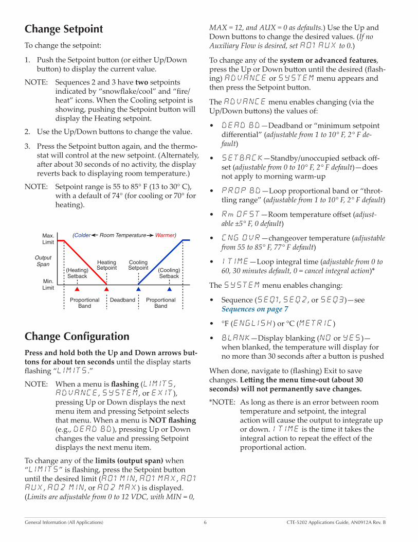
Change SetpointTo change the setpoint:
1. Push the Setpoint button (or either Up/Down button) to display the current value.
NOTE: Sequences 2 and 3 have two setpoints indicated by “snowflake/cool” and “fire/heat” icons. When the Cooling setpoint is showing, pushing the Setpoint button will display the Heating setpoint.
2. Use the Up/Down buttons to change the value.
3. Press the Setpoint button again, and the thermo-stat will control at the new setpoint. (Alternately, after about 30 seconds of no activity, the display reverts back to displaying room temperature.)
NOTE: Setpoint range is 55 to 85° F (13 to 30° C), with a default of 74° (for cooling or 70° for heating).
MAX = 12, and AUX = 0 as defaults.) Use the Up and Down buttons to change the desired values. (If no Auxiliary Flow is desired, set AO1 AUX to 0.)
To change any of the system or advanced features, press the Up or Down button until the desired (flash-ing) ADVANCE or SYSTEM menu appears and then press the Setpoint button.
The ADVANCE menu enables changing (via the Up/Down buttons) the values of:
• DEAD BD—Deadband or “minimum setpoint differential” (adjustable from 1 to 10° F, 2° F de-fault)
• SETBACK—Standby/unoccupied setback off-set (adjustable from 0 to 10° F, 2° F default)—does not apply to morning warm-up
• PROP BD—Loop proportional band or “throt-tling range” (adjustable from 1 to 10° F, 2° F default)
• Rm OFST—Room temperature offset (adjust-able ±5° F, 0 default)
• CNG OVR—changeover temperature (adjustable from 55 to 85° F, 77° F default)
• I TIME—Loop integral time (adjustable from 0 to 60, 30 minutes default, 0 = cancel integral action)*
The SYSTEM menu enables changing:
• Sequence (SEQ1, SEQ2, or SEQ3)—see Sequences on page 7
• °F (ENGLISH) or °C (METRIC)
• BLANK—Display blanking (NO or YES)—when blanked, the temperature will display for no more than 30 seconds after a button is pushed
When done, navigate to (flashing) Exit to save changes. Letting the menu time-out (about 30 seconds) will not permanently save changes.
*NOTE: As long as there is an error between room temperature and setpoint, the integral action will cause the output to integrate up or down. I TIME is the time it takes the integral action to repeat the effect of the proportional action.
(Colder Room Temperature Warmer)
Cooling Setpoint
Heating Setpoint
ProportionalBand
ProportionalBand
Deadband
(Cooling)Setback
(Heating)Setback
Max.Limit
Min.Limit
Output Span
General Information (All Applications) 7 CTE-5202 Applications Guide, AN0912A Rev. B
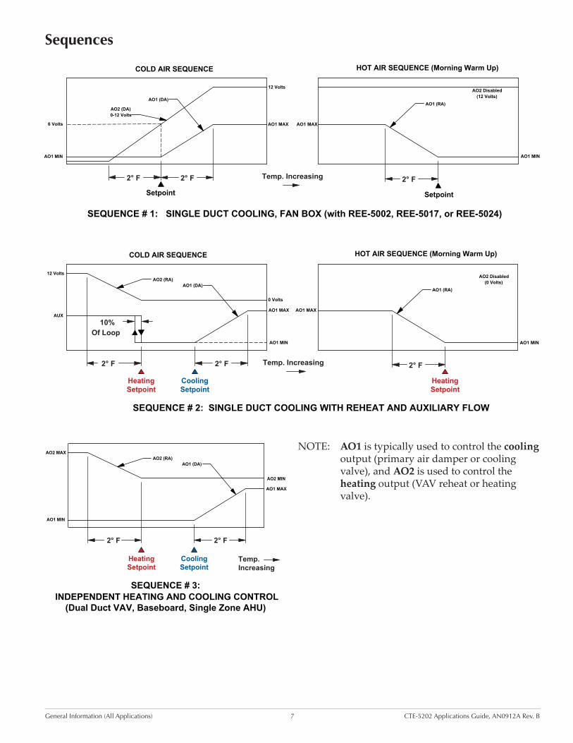
NOTE: AO1 is typically used to control the cooling output (primary air damper or cooling valve), and AO2 is used to control the heating output (VAV reheat or heating valve).
2° F 2° F 2° F
AO2 Disabled(12 Volts)
SEQUENCE # 1: SINGLE DUCT COOLING, FAN BOX (with REE-5002, REE-5017, or REE-5024)
COLD AIR SEQUENCE
12 Volts
AO2 (DA)0-12 Volts
AO1 (DA)
Setpoint
AO1 MIN
HOT AIR SEQUENCE (Morning Warm Up)
AO1 (RA)
AO1 MAX AO1 MAX
AO1 MIN
Temp. Increasing
6 Volts
Setpoint
2° F
Of Loop10%
2° F 2° F
AO1 MIN
AO1 MAXAO1 MAX
AO1 (RA)
HOT AIR SEQUENCE (Morning Warm Up)
AUX
AO1 MIN
COLD AIR SEQUENCE
AO1 (DA)AO2 (RA)
0 Volts
12 Volts
SEQUENCE # 2: SINGLE DUCT COOLING WITH REHEAT AND AUXILIARY FLOW
AO2 Disabled(0 Volts)
Temp. Increasing
CoolingSetpoint
HeatingSetpoint
HeatingSetpoint
SEQUENCE # 3: INDEPENDENT HEATING AND COOLING CONTROL
(Dual Duct VAV, Baseboard, Single Zone AHU)
AO2 MAX
AO2 MIN
AO2 (RA)AO1 (DA)
AO1 MIN
AO1 MAX
CoolingSetpoint
HeatingSetpoint
Temp.Increasing
2° F 2° F
Sequences

General Information (All Applications) 8 CTE-5202 Applications Guide, AN0912A Rev. B
Cross-References
Thermostat ReplacedCTE-5202SequenceSelected
ExampleReplacementApplicationsKMC /
Nailor / Dynacon*
Anemostat (East/West)*
Metal Industries*
Metalaire* Nailor*ASC / Titus*
CTE-100113-27, 004100
10027401 #1 See page 32
CTE-1002
#3 (disregard cooling setpoint) or #1 (with
8K–10K ohm resistor for RA mode)
CTE-1003 13-29 01EC-2146B3-3001-
015 or B3-015
#3
CTE-1004 13-28 01EC-2129 THM1004 10027403 #2 See page 34 and page 36
CTE-1005 THM1005#1 (setback used for night
setpoint)
CTE-1008#1 (setback used for day
setpoint)
CTE-1101 004643 THM1101 10027415 #1See page 32, page 37, and
page 38
CTE-1103 01EC-9229 THM1103 10027411#1 (single duct) or #3
(dual duct)See page 35, page 39, and
page 40
CTE-1105 THM1105 10027413 #1
CTE-1108#1 (setback used for day
setpoint)
*NOTE: CTE-1x0x thermostats require a power supply of 9.1 VDC, typically supplied by a CEP/CSP-4xxx controller/actuator, and they have a 0–6 VDC output range. The CTE-5202 can also operate on the 9.1 VDC power supplied by CEP/CSP-4xxx controller-actuators, but the CTE-5202’s outputs will be reduced to a maximum of about 5.3 VDC (or a maximum of about 2000 fpm from the CEP/CSP-4xxx). In almost all such applications, this is adequate. In a rare application that requires a full 6 VDC output (or 3000 fpm maximum from the CEP/CSP-4xxx), the CTE-5202 can be powered by the 24 VAC transformer, which can be easily done by switching the wire from Terminal #5 (+9.1 VDC) to Terminal #10 (24 VAC, phase) on the CEP/CSP-4xxx. See 9.1 VDC vs. 24 VAC Power Options on page 31. See also the CEP-4000 Series Applications Guide.
Barber Colman (TAC, Invensys, Schneider Electric)
Thermostat ReplacedCTE-5202 Sequence Selected
TP-8101, TP-8102, and TP-8103 #1
TP-8124 and TP-8125 #3
For wiring and sample applications, see Barber Colman TP-81xx Thermostats Replacement Applications on page 41.

General Information (All Applications) 9 CTE-5202 Applications Guide, AN0912A Rev. B
Thermostat ReplacedCTE-5202 Sequence Selected
Example Replacement Applications
KMC / Nailor / Dynacon*
Anemostat* Carnes*Metal
Industries*Nailor*
Price Industries*
ASC / Titus*
CTE-5101 999-2662 01EC-2119B3-3001-191
or B3-191019814-001
10269601 / 10269606
#1See page 20, page 21, and
page 28
CTE-5102 13-33 10269607#3 (if T4 is not
used)See page 20
CTE-5103 13-35 999-2663 01EC-2122B3-3001-186
or B3-186019810-001
10269608 / 10269603
#3 (if T3 and T4 are not
used)
See page 22, page 24, page
25, page 26, and page 29
CTE-5104 13-34 999-2664 01EC-2120 H1-981019726-001 / 019816-
001
10269604 / 10269609
#2See page 22, page 23, and
page 27
CTE-5105 019822-001 10269610
#1 (if the setback feature is acceptable
in place of two independent
setpoints)
*NOTE: CTE-510x thermostats require a power supply of 14–20 VDC, typically using the 16 VDC power supplied by a CSP-5101/5102 controller/actuator. The CTE-5202 can use the same 16 VDC power (or 14–35 VDC or 24 VAC). See also the CSP-5001/5002 Applications Guide.
KMC CTE-50xx
Thermostat ReplacedCTE-5202 Sequence Selected Example Replacement Applications
CTE-5001/5011* #1 See page 32 and page 35 (9.1 VDC)
CTE-5002/5012* #2 See page 34 (9.1 VDC)
CTE-5003/5013* (No Replacement) (9.1 VDC)
CTE-5006/5016** #2 See page 22 (16 VDC)
CTE-5015** #1 See page 20 (16 VDC)
*NOTE: These models require a power supply of 9.1 VDC, typically supplied by a CEP/CSP-4xxx controller/actuator, and they have a 0–6 VDC output range. See the discussion on 9.1 VDC power under the CTE-1x0x cross-reference NOTE on page 8. Need for the REE-1014 in applications is eliminated.**NOTE: These models require a power supply of 14–20 VDC, typically using the 16 VDC power supplied by a CSP-5101/5102 controller/actuator. The CTE-5202 can use the same 16 VDC power (or 14–35 VDC or 24 VAC).
Other thermostats that the CTE-5202 can be a functional/upgrade replacement for include:
• Honeywell TB7980 (check application and specifications)
• Johnson Controls (various—check application and specifications)
• Kele RTC-2P (with one or less remote inputs—check application and specifications)
• PEKO (various—check application and specifications)
• Siemens (various—check application and specifications)
• Viconics (various—check application and specifications)

General Information (All Applications) 10 CTE-5202 Applications Guide, AN0912A Rev. B
Troubleshooting
Display Is Blank• If the display comes on for no more than 30
seconds after a button is pushed and then blanks out, Display Blanking is enabled in the SYS-TEM menu. See Change Configuration on page 6.
• Check for a tripped circuit breaker to the trans-former.
• Check for proper supply voltage from the transformer and that the transformer has enough capacity (VA) for all connected devices (see their respective data sheets).
Setpoint Is Not Maintained• Check that room temperature is being sensed
correctly. See Temperature Reading Is Incorrect on page 10.
• Check that the appropriate sequence is selected in the SYSTEM menu. See Change Configura-tion on page 6 and the relevant sample applica-tion.
• If changeover is used on AI1, check the sensor and the changeover setting in the ADVANCE menu. If a resistor is used on AI1 to force a changeover without a temperature sensor, the value of the resistor may be too high or too low. See External Input (AI1) on page 5, Change Configuration on page 6, and the relevant sample application.
• If a setback switch/relay is used on AI1, the switch may be (stuck) in the setback position. See page 23.
• If an override switch/relay is used on AO1, the switch may be (stuck) in the override position. See page 18, page 21, and page 33.
• Check settings of auxiliary flow and other limits as relevant in the LIMITS menu. See Change Configuration on page 6.
• If the HVAC system has trouble recovering from the unoccupied setback to the occupied setpoint during very cold weather, adjust the setback in the ADVANCE menu. See Change Configura-tion on page 6.
• If space temperature is overshooting the setpoint or oscillating, try increasing the proportional band by a degree in the ADVANCE menu. If the problem persists, try increasing the integral value slightly (up to 20%). If the problem still persists, try setting the integral value to 0. (The optimal integral value is dependent on the characteristics of the particular space and HVAC system.) See Change Configuration on page 6.
Temperature Reading Is Incorrect• Check that the correct °F/C temperature scale
is selected in the SYSTEM menu. See Change Configuration on page 6.
• If the discrepancy is small, adjust the room temperature offset in the ADVANCE menu. See Change Configuration on page 6.
• Check that the thermostat is NOT mounted on an exterior wall, mounted on or near a large thermal mass (e.g., concrete block wall), blocked from normal air circulation by obstructions, exposed to heat sources (e.g., lights, computers, copiers, coffee makers) or to sunlight (at any time of the day), exposed to drafts from win-dows or air vents, or exposed to air flow through the conduit from leaks in plenum ducts (put plumber’s putty or other sealant inside conduit to block air leaks).
Wiring Issues• Check for correct wiring for the application. See
Connections on page 5 and the various applica-tion examples in this document.
• Remove the thermostat from the backplate and inspect the terminals for loose wires. See the CTE-5202 Installation Guide.
• Check the wiring at the connected devices.
• Use a voltmeter and ohmmeter to check the terminals for expected values.
NOTE: Wiring must be adequate to avoid excessive voltage drop on long runs! Allow plenty of “cushion” in measurements A meter may be too slow to register transient dips or peaks during startup.

Single-Zone Heating and Cooling Applications 11 CTE-5202 Applications Guide, AN0912A Rev. B
Single-Zone Proportional Heating and
Cooling Applications
This section gives sample applications for using the CTE-5202 in single zone proportional heating (baseboard heaters) and cooling (chilled beams) with valves or SCR control.

Single-Zone Heating and Cooling Applications 12 CTE-5202 Applications Guide, AN0912A Rev. B
Heating, RA and DA
~TT
AI1
AO
1A
O2
CTE-5202
Thermostat
24 VAC
~–
(Phase)(Neutral)
(5K–10K Ohm
Resistor between
AI1 and Common
for RA Mode Only)
24 V
AC
Co
mm
on
Inp
ut
Valve
Select Sequence 1
Select Sequence 1 Select Sequence 1AND Set Changeover to 55° F
CTE-5202 thermostats can use a variety of valves for heating/cooling applications with hot and chilled water. For Reverse Acting control, connect a 5K to 10K ohm resistor between Common and AI1. Select Sequence 1 (from the CTE-5202 SYSTEM menu) and lower the Changeover (in the ADVANCE menu) to the lowest setting (55° F). See Change Configuration on page 6. The resistor simulates a changeover sensor and puts the thermostat in Re-verse Acting mode.
NOTE: If the resistor value is too high, the thermostat will not go into RA mode. If the resistor value is too low, the thermostat may go into setback mode.
This RA control works for NO 2–10 and 0–10 VDC valves or NC 10–2 and 10–0 VDC valves as well as equivalent SCR controls.
For Direct Acting control, select Sequence 1 (from the CTE-5202 SYSTEM menu). See Change Con-figuration on page 6. (Do not connect the resistor.)
This DA control works for NC 2–10 and 0–10 VDC valves or NO 10–2 and 10–0 VDC valves as well as equivalent SCR controls.
RA Heating
Heating Valve Open
Setpoint
(Colder Room Temperature Warmer)
Setpoint
(Colder Room Temperature Warmer)
AO1 Signal
DA Heating
AO1 Signal
Heating Valve Open
HeatingValve Closed
HeatingValve Closed
10 VDC 10 VDC
Single-Zone Heating and Cooling Applications 13 CTE-5202 Applications Guide, AN0912A Rev. B
Chilled Beam Cooling
~TT
AI1
AO
1A
O2
CTE-5202
Thermostat
24 VAC
~–
(Phase)(Neutral)
24 V
AC
Co
mm
on
Inp
ut
Valve Select Sequence 1
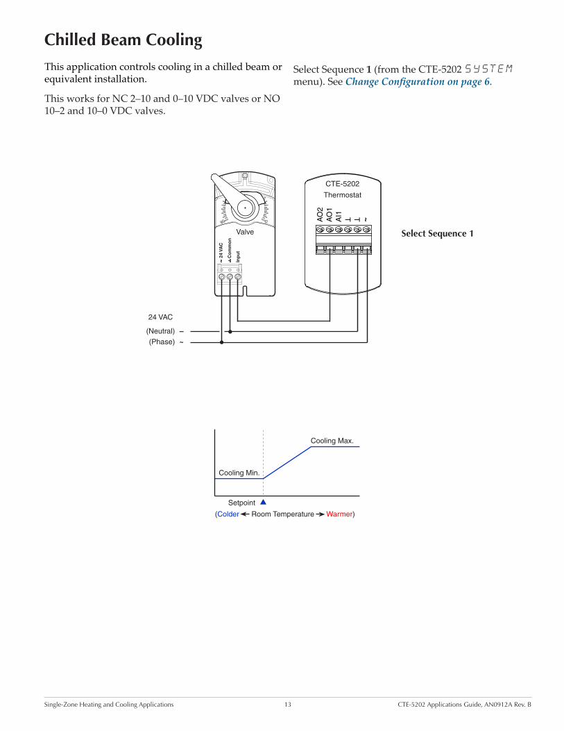
This application controls cooling in a chilled beam or equivalent installation.
This works for NC 2–10 and 0–10 VDC valves or NO 10–2 and 10–0 VDC valves.
Select Sequence 1 (from the CTE-5202 SYSTEM menu). See Change Configuration on page 6.
Cooling Max.
Cooling Min.
Setpoint
(Colder Room Temperature Warmer)

Single-Zone Heating and Cooling Applications 14 CTE-5202 Applications Guide, AN0912A Rev. B
Chilled Beam 4-Pipe Heating and Cooling
~TT
AI1
AO
1A
O2
CTE-5202
Thermostat
24 VAC
~–
(Phase)(Neutral)
24 V
AC
Co
mm
on
Inp
ut
Cooling Valve
24 V
AC
Co
mm
on
Inp
ut
Heating Valve
Select Sequence 3
AO2 MAX
AO2 MIN
AO2 (RA)AO1 (DA)
AO1 MIN
AO1 MAX
CoolingSetpoint
HeatingSetpoint
Temp.Increasing
2° F 2° F
This application enables both heating and cooling in a chilled beam and baseboard or equivalent installation.
This works for NC 2–10 and 0–10 VDC valves or NO 10–2 and 10–0 VDC valves.
Select Sequence 3 from the CTE-5202 SYSTEM menu. See Change Configuration on page 6.
Single-Zone Heating and Cooling Applications 15 CTE-5202 Applications Guide, AN0912A Rev. B
Chilled Beam 2-Pipe Heating and Cooling with Changeover
~TT
AI1
AO
1A
O2
CTE-5202
Thermostat
24 VAC
~–
(Phase)(Neutral)
24 V
AC
Co
mm
on
Inp
ut
Valve
STE-1454/1455 Strap-On Sensor on Supply Pipe
Select Sequence 1
2° F 2° F 2° F
COLD SEQUENCE
AO1 (DA)
Setpoint
AO1 MIN
HOT SEQUENCE
AO1 (RA)
AO1 MAX AO1 MAX
AO1 MIN
Temp. Increasing
Setpoint
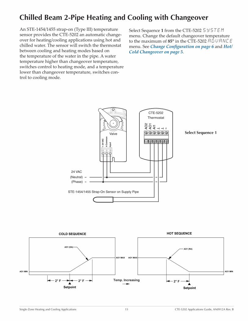
An STE-1454/1455 strap-on (Type III) temperature sensor provides the CTE-5202 an automatic change-over for heating/cooling applications using hot and chilled water. The sensor will switch the thermostat between cooling and heating modes based on the temperature of the water in the pipe. A water temperature higher than changeover temperature, switches control to heating mode, and a temperature lower than changeover temperature, switches con-trol to cooling mode.
Select Sequence 1 from the CTE-5202 SYSTEM menu. Change the default changeover temperature to the maximum of 85° in the CTE-5202 ADVANCE menu. See Change Configuration on page 6 and Hot/Cold Changeover on page 5.

Pressure Dependent VAV Applications with MEP-4002 16 CTE-5202 Applications Guide, AN0912A Rev. B
Pressure Dependent VAV
Applications with MEP-4002
This section gives sample applications for using the CTE-5202 with the MEP-4002 actuator in pressure dependent VAV applications.
The MEP-4002’s default direction is CCW to close (CW to open or CW with increasing voltage), but this can be reversed by a switch during installation and configuration.
See also the MEP-4000 Series Installation Guide.
For additional applications, see Pressure Indepen-dent VAV Applications with CSP-5001/5002 on page 19 and make the corresponding wiring adjustments for power to the MEP-4002 and CTE-5202.

Pressure Dependent VAV Applications with MEP-4002 17 CTE-5202 Applications Guide, AN0912A Rev. B
~TT
AI1
AO
1A
O2
CTE-5202
Thermostat
24 VAC @ 5 VA
~–
(Phase)(Neutral)
(5K–10K
Ohm Resistor
between AI1
and Common
for Heating
Mode Only)
MEP-4002
Actuator
24 V
AC
Co
mm
on
Inp
ut
Ou
t
Cooling or Heating
CTE-5202 thermostats can use MEP-4002 actuators to operate damper boxes in a pressure-dependent VAV system. As shown in the diagram, a “requested flow” voltage signal (AO1) is connected to the MEP-4002 to adjust airflow from minimum to maximum flow according to space demand. Minimum and maximum flow limit adjustments can be made at the thermostat (recommended) or at the actuator. (See the MEP-4000 Series Installation Guide.)
For cooling, select Sequence 1 (from the CTE-5202 SYSTEM menu). See Change Configuration on page 6.
Heating Air
Heating Max.
Heating Min.
1650 fpm
0 fpmSetpoint
(Colder Room Temperature Warmer)
3300 fpm
Cooling Max.
Cooling Min.
1650 fpm
0 fpmSetpoint
(Colder Room Temperature Warmer)
3300 fpm
AO1 Signal
Cooling Air
AO1 Signal
Select Sequence 1 Select Sequence 1AND set Changeover to 55° F
For heating, connect a 5K to 10K ohm resistor between Common and AI1. Select Sequence 1 and lower the Changeover to the lowest setting (55° F). See Change Configuration on page 6. The resistor simulates a changeover sensor and puts the thermo-stat in Reverse Acting mode.
NOTE: If the resistor value is too high, the thermostat will not go into RA mode. If the resistor value is too low, the thermostat may go into setback mode.
Pressure Dependent VAV Applications with MEP-4002 18 CTE-5202 Applications Guide, AN0912A Rev. B
Other ApplicationsSee the corresponding application in Pressure Independent VAV Applications with CSP-5001/5002 on page 19 and make the corresponding wiring adjust-ments for power to the MEP-4002 and CTE-5202. The MEP-4002’s default direction is the same as the CSP-5001.
~TT
AI1
AO
1A
O2
CTE-5202
Thermostat
24 VAC @ 5 VA
~–
(Phase)(Neutral)
(5K–10K
Ohm Resistor
between AI1
and Common
for Heating
Mode Only)
NC SPST Relay
(Override to Fully Closed)
MEP-4002
Actuator
24 V
AC
Co
mm
on
Inp
ut
Ou
t
Auto and Override (to Fully Closed)
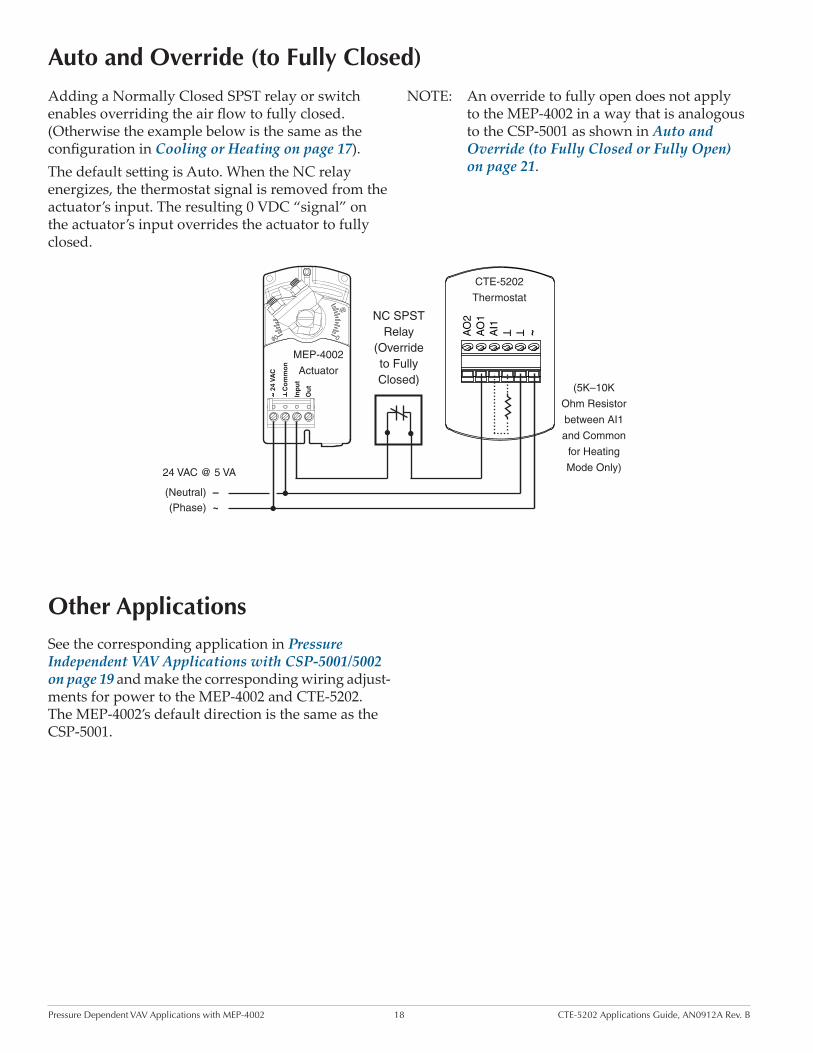
Adding a Normally Closed SPST relay or switch enables overriding the air flow to fully closed. (Otherwise the example below is the same as the configuration in Cooling or Heating on page 17).The default setting is Auto. When the NC relay energizes, the thermostat signal is removed from the actuator’s input. The resulting 0 VDC “signal” on the actuator’s input overrides the actuator to fully closed.
NOTE: An override to fully open does not apply to the MEP-4002 in a way that is analogous to the CSP-5001 as shown in Auto and Override (to Fully Closed or Fully Open) on page 21.

Pressure Independent VAV Applications with CSP-5001/5002 19 CTE-5202 Applications Guide, AN0912A Rev. B
Pressure Independent VAV
Applications with CSP-5001/5002
This section gives sample applications for using the CTE-5202 as a substitute for the CTE-5100 series thermostats with the CSP-5001/5002 VAV controller-actuator.
Factory-set rotation direction of the CSP-5001 is CCW to close (CW to open or CW with increasing voltage), and the CSP-5002’s is CW to close (CCW to open or CCW with increasing voltage). The direc-tion can be reversed by changing the position of a jumper. The CSP-5001 (with default direction) is used in the examples of this section.
See also the CSP-5001/5002 Applications Guide.
Concerning replacements of the CTE-510x thermo-stats, see Cross-References on page 8.
To manually open the box, remove wiring from Terminal IN and jumper Terminal IN to Terminal 16 VDC. This will tell unit to control at 3300 fpm (full airflow), the green LED should turn on, and the box should drive open).
To manually close the box, remove wiring from Terminal IN, and jumper Terminal IN to Terminal –. This will tell unit to control at zero fpm (no airflow), the red LED should be on and the box should drive closed.
NOTE: Full rotation may take five to six minutes because the actuator rotates at 18° per minute.
Pressure Independent VAV Applications with CSP-5001/5002 20 CTE-5202 Applications Guide, AN0912A Rev. B
Cooling or Heating
~TT
AI1
AO
1A
O2
CTE-5202
Thermostat
CSP-5001
Controller-Actuator
H
~
16V
DCIN
OUT ––
L
24 VAC
(To Flow Sensor)
24 VAC @ 4 VA
~
–
(Phase)
(Neutral)
(5K–10K
Ohm Resistor
between AI1
and Common
for Heating
Mode Only)
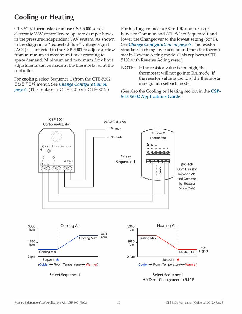
CTE-5202 thermostats can use CSP-5000 series electronic VAV controllers to operate damper boxes in the pressure-independent VAV system. As shown in the diagram, a “requested flow” voltage signal (AO1) is connected to the CSP-5001 to adjust airflow from minimum to maximum flow according to space demand. Minimum and maximum flow limit adjustments can be made at the thermostat or at the controller.
For cooling, select Sequence 1 (from the CTE-5202 SYSTEM menu). See Change Configuration on page 6. (This replaces a CTE-5101 or a CTE-5015.)
Heating Air
Heating Max.
Heating Min.
1650 fpm
0 fpmSetpoint
(Colder Room Temperature Warmer)
3300 fpm
Cooling Max.
Cooling Min.
1650 fpm
0 fpmSetpoint
(Colder Room Temperature Warmer)
3300 fpm
AO1 Signal
Cooling Air
AO1 Signal
Select Sequence 1 Select Sequence 1AND set Changeover to 55° F
For heating, connect a 5K to 10K ohm resistor between Common and AI1. Select Sequence 1 and lower the Changeover to the lowest setting (55° F). See Change Configuration on page 6. The resistor simulates a changeover sensor and puts the thermo-stat in Reverse Acting mode. (This replaces a CTE-5102 with Reverse Acting reset.)
NOTE: If the resistor value is too high, the thermostat will not go into RA mode. If the resistor value is too low, the thermostat may go into setback mode.
(See also the Cooling or Heating section in the CSP-5001/5002 Applications Guide.)
Select Sequence 1
Pressure Independent VAV Applications with CSP-5001/5002 21 CTE-5202 Applications Guide, AN0912A Rev. B
Auto and Override (to Fully Closed or Fully Open)
CSP-5001
Controller-Actuator
H
~
16V
DCIN
OUT ––
L
24 VAC
(To Flow Sensor)
24 VAC @ 4 VA~
–
~TT
AI1
AO
1A
O2
CTE-5202
Thermostat
(Phase)
(Neutral)
SPDT Relay
CSP-5001
Controller-Actuator
H
~
16V
DCIN
OUT ––
L
24 VAC
(To Flow Sensor)
24 VAC @ 4 VA~
–
(Phase)
(Neutral)
SPDT Relay
~TT
AI1
AO
1A
O2
CTE-5202
Thermostat
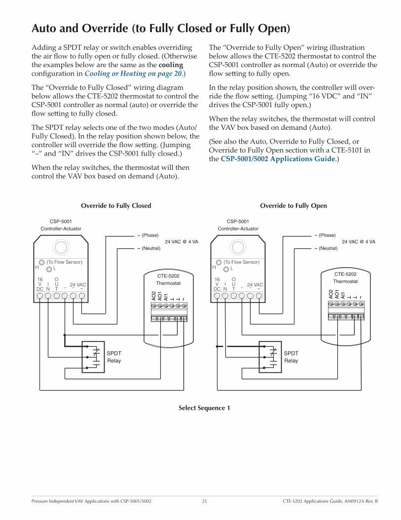
Adding a SPDT relay or switch enables overriding the air flow to fully open or fully closed. (Otherwise the examples below are the same as the cooling configuration in Cooling or Heating on page 20.)
The “Override to Fully Closed” wiring diagram below allows the CTE-5202 thermostat to control the CSP-5001 controller as normal (auto) or override the flow setting to fully closed.
The SPDT relay selects one of the two modes (Auto/Fully Closed). In the relay position shown below, the controller will override the flow setting. (Jumping “–” and “IN” drives the CSP-5001 fully closed.)
When the relay switches, the thermostat will then control the VAV box based on demand (Auto).
The “Override to Fully Open” wiring illustration below allows the CTE-5202 thermostat to control the CSP-5001 controller as normal (Auto) or override the flow setting to fully open.
In the relay position shown, the controller will over-ride the flow setting. (Jumping “16 VDC” and “IN” drives the CSP-5001 fully open.)
When the relay switches, the thermostat will control the VAV box based on demand (Auto).
(See also the Auto, Override to Fully Closed, or Override to Fully Open section with a CTE-5101 in the CSP-5001/5002 Applications Guide.)
Override to Fully Closed Override to Fully Open
Select Sequence 1

Pressure Independent VAV Applications with CSP-5001/5002 22 CTE-5202 Applications Guide, AN0912A Rev. B
~TT
AI1
AO
1A
O2
CTE-5202
Thermostat
CSP-5001
Controller-Actuator
H
~
16V
DCIN
OUT ––
L
24 VAC
REE-5001 Relay Module
~–
24 V
AC
32
1
Stag
es
3-St
age
Reh
eat T
(To Flow Sensor)
24 VAC @ 34 VA~
–
24 VAC Contactors
(10 VA Max. per Stage)
2
1
3
Load
(Phase)
(Neutral)
Select Sequence 2, with or without Auxiliary Flow
Cooling and 3-Stage Reheat
This application uses a CSP-5001 along with an REE-5001 relay module and three 24 VAC contactors for three stages of reheat.
As the temperature drops below setpoint, the first stage of reheat begins. As the temperature continues to drop, the second stage and later the third stage begin as needed.
Select Sequence 2 (from the CTE-5202 SYSTEM menu), with or without Auxiliary Flow (AO1 AUX in LIMITS menu). See Change Configuration on page 6.
(See also the Cooling with 3-Stage Reheat section with a CTE-5104 for auxiliary flow or a CTE-5103 without auxiliary flow in the CSP-5001/5002 Appli-cations Guide.)
NOTE: Triac outputs on the REE-5001 are for 24 VAC loads only. The phase side of the transformer connects to the “common” side of the load (contactors).
NOTE: See also the REE-5001 Installation Guide.
2° F
Of Loop10%
2° F
AO1 MAXAUX
AO1 MIN
COLD AIR SEQUENCE
0 Volts
12 Volts
Temp. IncreasingCoolingSetpoint
HeatingSetpoint
9.5 V
3.5 V
#3
#1
6.5 V
#2
Reheat Stages
AO2 (RA)
AO1 (DA)

Pressure Independent VAV Applications with CSP-5001/5002 23 CTE-5202 Applications Guide, AN0912A Rev. B
Cooling with 3-Stage Reheat and Night Setback/Setup
~TT
AI1
AO
1A
O2
CTE-5202
Thermostat
CSP-5001
Controller-Actuator
H
~
16V
DCIN
OUT ––
L
24 VAC
REE-5001 Relay Module
~–
24 V
AC
32
1
Stag
es
3-St
age
Reh
eat T
(To Flow Sensor)
24 VAC @ 34 VA~
–
24 VAC Contactors
(10 VA Max. per Stage)
2
1
3
Load
(Phase)
(Neutral)
SPST
Relay
This configuration is the same as on the previous page except for the addition of a SPST relay or switch. See Cooling and 3-Stage Reheat on page 22.
The switch or relay is driven by a night setback/setup signal from other equipment not shown. When the contact is closed (e.g., by a timer), setback/setup mode initiates, changing the setpoint by the offset selected in ADVANCE > SETBACK menu. See Change Configuration on page 6 and Unoccupied/Standby Setback on page 5.
NOTE: Standby/unoccupied setback offset does not apply to morning warm-up.
NOTE: This configuration requires the system fan to be on during setback/setup mode.
NOTE: Triac outputs on the REE-5001 are for 24 VAC loads only. The phase side of the transformer connects to the “common” side of the load (contactors).
NOTE: See also the REE-5001 Installation Guide.
(See also the Cooling with 3-Stage Reheat and Night Setback/Setup section with a CTE-5104 in the CSP-5001/5002 Applications Guide.)
Select Sequence 2, with or without Auxiliary Flow
Pressure Independent VAV Applications with CSP-5001/5002 24 CTE-5202 Applications Guide, AN0912A Rev. B
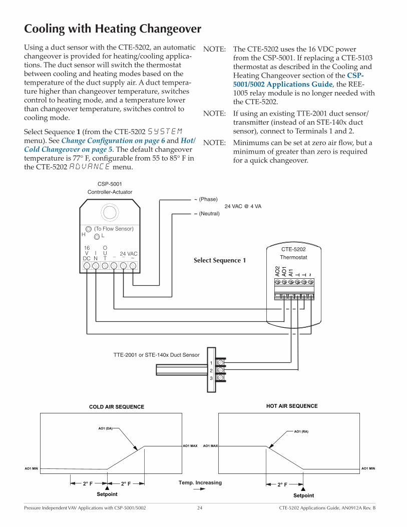
Cooling with Heating ChangeoverUsing a duct sensor with the CTE-5202, an automatic changeover is provided for heating/cooling applica-tions. The duct sensor will switch the thermostat between cooling and heating modes based on the temperature of the duct supply air. A duct tempera-ture higher than changeover temperature, switches control to heating mode, and a temperature lower than changeover temperature, switches control to cooling mode.
Select Sequence 1 (from the CTE-5202 SYSTEM menu). See Change Configuration on page 6 and Hot/Cold Changeover on page 5. The default changeover temperature is 77° F, configurable from 55 to 85° F in the CTE-5202 ADVANCE menu.
NOTE: The CTE-5202 uses the 16 VDC power from the CSP-5001. If replacing a CTE-5103 thermostat as described in the Cooling and Heating Changeover section of the CSP-5001/5002 Applications Guide, the REE-1005 relay module is no longer needed with the CTE-5202.
NOTE: If using an existing TTE-2001 duct sensor/transmitter (instead of an STE-140x duct sensor), connect to Terminals 1 and 2.
NOTE: Minimums can be set at zero air flow, but a minimum of greater than zero is required for a quick changeover.
2° F 2° F 2° F
COLD AIR SEQUENCE
AO1 (DA)
Setpoint
AO1 MIN
HOT AIR SEQUENCE
AO1 (RA)
AO1 MAX AO1 MAX
AO1 MIN
Temp. Increasing
Setpoint
~TT
AI1
AO
1A
O2
CTE-5202
Thermostat
CSP-5001
Controller-Actuator
H
~
16V
DCIN
OUT ––
L
24 VAC
(To Flow Sensor)
24 VAC @ 4 VA~
–
(Phase)
(Neutral)
1
2
3
TTE-2001 or STE-140x Duct Sensor
Select Sequence 1

Pressure Independent VAV Applications with CSP-5001/5002 25 CTE-5202 Applications Guide, AN0912A Rev. B
Cooling with Heating Changeover and Electric Reheat
This configuration is the same as the previous page except for the addition of an REE-5001 relay module connected to AO2 (for three stages of reheat) and selecting Sequence 2 from the CTE-5202 SYSTEM menu. See Change Configuration on page 6, Hot/Cold Changeover on page 5 and Cooling with Heating Changeover on page 24. See also Cooling and 3-Stage Reheat on page 22.
~TT
AI1
AO
1A
O2
CTE-5202
Thermostat
CSP-5001
Controller-Actuator
H
~
16V
DCIN
OUT ––
L
24 VAC
REE-5001 Relay Module
~–
24 V
AC
32
1
Stag
es
3-St
age
Reh
eat T
(To Flow Sensor)
24 VAC @ 34 VA~
–
24 VAC Contactors
(10 VA Max. per Stage)
2
1
3
Load
(Phase)
(Neutral)
1 2 3
TTE-2001 or
STE-140x
Duct Sensor
2° F
Of Loop10%
2° F 2° F
AO1 MIN
AO1 MAXAO1 MAX
AO1 (RA)
HOT AIR SEQUENCE (Morning Warm Up)
AUX
AO1 MIN
COLD AIR SEQUENCE
0 Volts
12 Volts AO2 Disabled(0 Volts)
Temp. Increasing
CoolingSetpoint
HeatingSetpoint
HeatingSetpoint
9.5 V
3.5 V
#3
#1
6.5 V
#2
Reheat Stages
AO2 (RA)
AO1 (DA)
NOTE: The CTE-5202 uses the 16 VDC power from the CSP-5001. If replacing a CTE-5103 thermostat as described in the Cooling with Heating Changeover and Electric Reheat section of the CSP-5001/5002 Applications Guide, the REE-1005 relay module is no longer needed with the CTE-5202.
NOTE: If using an existing TTE-2001 duct sensor/transmitter (instead of an STE-140x duct sensor), connect to Terminals 1 and 2.
NOTE: Minimums can be set at zero air flow, but a minimum of greater than zero is required for a quick changeover.
Select Sequence 2
NOTE: Triac outputs on the REE-5001 are for 24 VAC loads only. The phase side of the transformer connects to the “common” side of the load (contactors).
NOTE: See also the REE-5001 Installation Guide.

Pressure Independent VAV Applications with CSP-5001/5002 26 CTE-5202 Applications Guide, AN0912A Rev. B
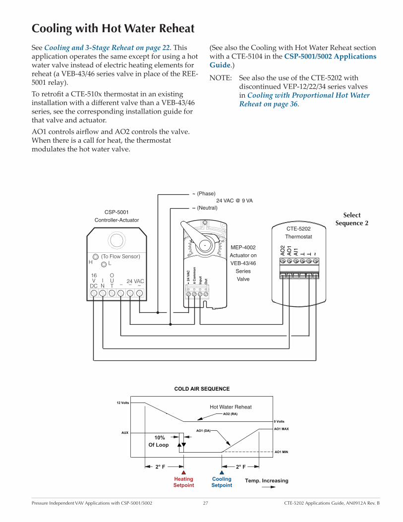
Cooling with Heating Changeover and Hot Water Reheat
See Cooling with Heating Changeover and Electric Reheat on page 25. This application operates the same except for using a hot water valve instead of electric heating elements for reheat (a VEB-43/46 series valve in place of the REE-5001 relay).
To retrofit a CTE-510x thermostat in an existing installation with a different valve than a VEB-43/46 series, see the corresponding installation guide for that valve and actuator.
When there is hot air in the duct, changeover initi-ates, allowing the heating signal from AO1 to control
~TT
AI1
AO
1A
O2
CTE-5202
Thermostat
CSP-5001
Controller-Actuator
H
~
16V
DCIN
OUT ––
L
24 VAC
(To Flow Sensor)
24 VAC @ 9 VA~
–
(Phase)
(Neutral)
1
2
3
TTE-2001 or STE-140x Duct Sensor
MEP-4002
Actuator on
VEB-43/46
Series
Valve24 V
AC
Co
mm
on
Inp
ut
Ou
t
2° F
Of Loop10%
2° F 2° F
AO1 MIN
AO1 MAXAO1 MAX
AO1 (RA)
HOT AIR SEQUENCE (Morning Warm Up)
AUX
AO1 MIN
COLD AIR SEQUENCE
0 Volts
12 Volts AO2 Disabled(0 Volts)
Temp. Increasing
CoolingSetpoint
HeatingSetpoint
HeatingSetpoint
(Hot Water Reheat) AO2 (RA)
AO1 (DA)
airflow and AO2 to control the valve. When there is a call for heat, the thermostat modulates the hot water valve.
NOTE: If using an existing TTE-2001 duct sensor/transmitter (instead of an STE-140x duct sensor), connect to Terminals 1 and 2.
NOTE: See also the Cooling with Heating Changeover and Hot Water Reheat section with a CTE-5103 in the CSP-5001/5002 Applications Guide.
SelectSequence 2
Pressure Independent VAV Applications with CSP-5001/5002 27 CTE-5202 Applications Guide, AN0912A Rev. B
Cooling with Hot Water Reheat
~TT
AI1
AO
1A
O2
CTE-5202
Thermostat
CSP-5001
Controller-Actuator
H
~
16V
DCIN
OUT ––
L
24 VAC
(To Flow Sensor)
24 VAC @ 9 VA~
–
(Phase)
(Neutral)
MEP-4002
Actuator on
VEB-43/46
Series
Valve24 V
AC
Co
mm
on
Inp
ut
Ou
t
See Cooling and 3-Stage Reheat on page 22. This application operates the same except for using a hot water valve instead of electric heating elements for reheat (a VEB-43/46 series valve in place of the REE-5001 relay).To retrofit a CTE-510x thermostat in an existing installation with a different valve than a VEB-43/46 series, see the corresponding installation guide for that valve and actuator.AO1 controls airflow and AO2 controls the valve. When there is a call for heat, the thermostat modulates the hot water valve.
(See also the Cooling with Hot Water Reheat section with a CTE-5104 in the CSP-5001/5002 Applications Guide.)
NOTE: See also the use of the CTE-5202 with discontinued VEP-12/22/34 series valves in Cooling with Proportional Hot Water Reheat on page 36.
SelectSequence 2
2° F
Of Loop10%
2° F
AO1 MAXAUX
AO1 MIN
COLD AIR SEQUENCE
0 Volts
12 Volts
Temp. IncreasingCoolingSetpoint
HeatingSetpoint
Hot Water Reheat AO2 (RA)
AO1 (DA)
Pressure Independent VAV Applications with CSP-5001/5002 28 CTE-5202 Applications Guide, AN0912A Rev. B
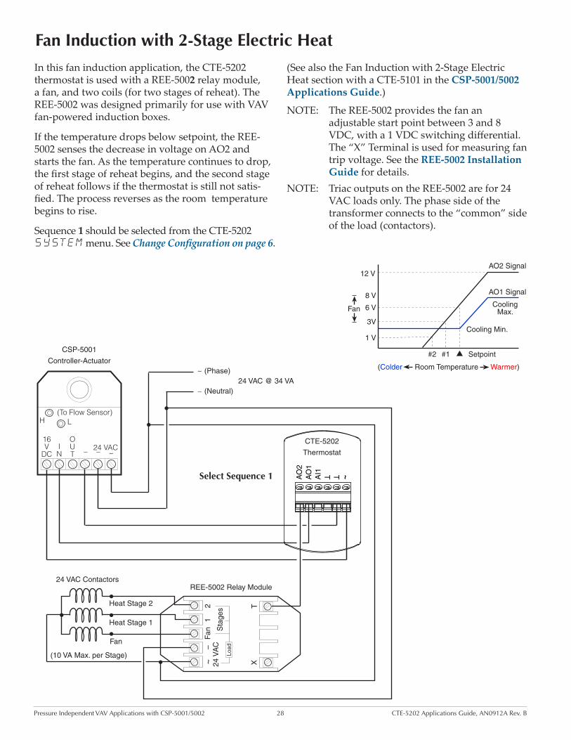
Fan Induction with 2-Stage Electric Heat
In this fan induction application, the CTE-5202 thermostat is used with a REE-5002 relay module, a fan, and two coils (for two stages of reheat). The REE-5002 was designed primarily for use with VAV fan-powered induction boxes.
If the temperature drops below setpoint, the REE-5002 senses the decrease in voltage on AO2 and starts the fan. As the temperature continues to drop, the first stage of reheat begins, and the second stage of reheat follows if the thermostat is still not satis-fied. The process reverses as the room temperature begins to rise.
Sequence 1 should be selected from the CTE-5202 SYSTEM menu. See Change Configuration on page 6.
~TT
AI1
AO
1A
O2
CTE-5202
Thermostat
CSP-5001
Controller-Actuator
H
~
16V
DCIN
OUT ––
L
24 VAC
REE-5002 Relay Module
(To Flow Sensor)
24 VAC @ 34 VA~
–
24 VAC Contactors
(10 VA Max. per Stage)
Heat Stage 1
Fan
(Phase)
(Neutral)
~–
24 V
AC
Fan
12
Sta
ges
XT
Load
Heat Stage 2
(See also the Fan Induction with 2-Stage Electric Heat section with a CTE-5101 in the CSP-5001/5002 Applications Guide.)
NOTE: The REE-5002 provides the fan an adjustable start point between 3 and 8 VDC, with a 1 VDC switching differential. The “X” Terminal is used for measuring fan trip voltage. See the REE-5002 Installation Guide for details.
NOTE: Triac outputs on the REE-5002 are for 24 VAC loads only. The phase side of the transformer connects to the “common” side of the load (contactors).
Select Sequence 1
Fan
(Colder Room Temperature Warmer)
AO2 Signal
Cooling Max.
Cooling Min.
AO1 Signal
Setpoint
6 V
1 V
3V
#2 #1
12 V
8 V

Pressure Independent VAV Applications with CSP-5001/5002 29 CTE-5202 Applications Guide, AN0912A Rev. B
Dual Duct, Minimum Air from Cold Duct
Dual duct applications can use two CSP-5001s with a CTE-5202. In this application, the CSP-5001s are mounted separately on the cold and hot air duct dampers with each using its own flow sensor.
The cold-deck controller receives the AO1 signal from the thermostat while the hot-deck controller receives its requested flow signal from AO2. Both CSP-5001s can be set independently for minimum and maximum flow settings.
~TT
AI1
AO
1A
O2
CTE-5202
Thermostat
CSP-5001
Controller-Actuator
H
~
16V
DCIN
OUT ––
L
24 VAC
(To Flow Sensor)
24 VAC @ 8 VA~
–
(Phase)
(Neutral)
CSP-5001
Controller-Actuator
H
~
16V
DCIN
OUT ––
L
24 VAC
(To Flow Sensor)
Cold Deck Hot Deck
Select Sequence 3 (from the CTE-5202 SYSTEM menu). See Change Configuration on page 6.
(See also the Dual Duct, Minimum Air from Cold Duct section with a CTE-5103 in the CSP-5001/5002 Applications Guide.)
Select Sequence
3
AO2 MAX
AO2 MIN
AO2 (RA)AO1 (DA)
AO1 MIN
AO1 MAX
CoolingSetpoint
HeatingSetpoint
Temp.Increasing
2° F 2° F

Pressure Independent VAV Applications with CEP/CSP-4000 Series 30 CTE-5202 Applications Guide, AN0912A Rev. B
Pressure Independent
This section gives sample applications for using the CTE-5202 as a substitute for the CTE-1000 series thermostats with the CEP/CSP-4000 series VAV controller-actuators. (See also the CEP-4000 Series Applications Guide.)
The CEP-4000 series uses SSE-1000/2000 series flow sensors, which are “hot wire anemometer” sensors. These sensors consists of two coils of wire mounted in the air stream: one monitors airflow, while the other is a reference used for duct temperature com-pensation. These sensors also include a temperature sensor for use with heating/cooling “changeover” applications (which requires an additional relay module).
The CSP-4000 series uses SSS-1000 series differential air flow sensors or a pitot tube instead of the SSE-1000/2000s. Otherwise wiring is the same as with the CEP-4000 series used in the examples here.
To manually drive the controller/damper open or closed (with 24 VAC on terminals 9 and 10), remove the wiring to terminal 6, and temporarily jumper terminal 6 to:
• Terminal 5 (9.1 VDC) = Open
• Terminal 4 (– VDC) = Closed
NOTE: Full rotation may take five to six minutes because the actuator rotates at 18° per minute.
Concerning replacements of the CTE-1x1x thermo-stats, see Cross-References on page 8.
VAV and CAV Applications
with CEP/CSP-4000 Series
CAUTIONDo not short terminals 12 and 14, 4 and 5, or 2 and 4.

Pressure Independent VAV Applications with CEP/CSP-4000 Series 31 CTE-5202 Applications Guide, AN0912A Rev. B
9.1 VDC vs. 24 VAC Power Options
The CTE-5202 can operate from the 9.1 VDC output supplied by the CEP/CSP-4xxx, but AO1 and AO2 will not be able to attain a full 6 VDC (e.g., a maxi-mum of about 5.3 VDC) output to the 0–6 VDC CEP/CSP-4xxx inputs. This means the maximum air flow controlled by the CEP-4xxx can be only around 2000 fpm instead of 3000 fpm. However, this will still cover nearly all applications.
(See the Voltage/Velocity Correlation chart in the CEP-4000 Series Applications Guide.)
~TT
AI1
AO
1A
O2
CTE-5202
Thermostat
24 VAC @ 10 VA
~
–
(Phase)
(Neutral)
7
6
5
4
3
2
1
8
9
10
11
12
13
14
CEP-4xxx
Controller-Actuator
24 VAC Power to CTE-5202
9.1 VDC Power to CTE-5202
OR (but NOT Both)
If more than about 2000 fpm is required, use 24 VAC from a transformer to power the CTE-5202. This can easily be done by connecting the ~ terminal on the CTE-5202 to Terminal 10 (24 VAC, phase) on the CEP-4xxx instead of Terminal 5 (+9.1 VDC).
CAUTIONConnect the CTE-5202 to the CEP-4xxx’s Terminal 5 OR 10, but not jumpered to both.
Pressure Independent VAV Applications with CEP/CSP-4000 Series 32 CTE-5202 Applications Guide, AN0912A Rev. B
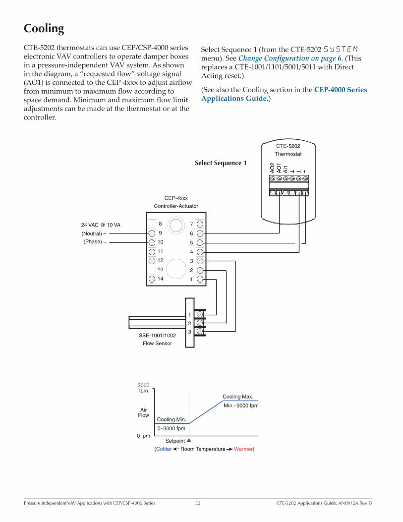
Cooling
~TT
AI1
AO
1A
O2
CTE-5202
Thermostat
24 VAC @ 10 VA
~
–
(Phase)
(Neutral)
1
2
3
7
6
5
4
3
2
1
8
9
10
11
12
13
14
CEP-4xxx
Controller-Actuator
SSE-1001/1002
Flow Sensor
������������
������������
�������������
���������������������������������������
�������
�������
�������������
����������
CTE-5202 thermostats can use CEP/CSP-4000 series electronic VAV controllers to operate damper boxes in a pressure-independent VAV system. As shown in the diagram, a “requested flow” voltage signal (AO1) is connected to the CEP-4xxx to adjust airflow from minimum to maximum flow according to space demand. Minimum and maximum flow limit adjustments can be made at the thermostat or at the controller.
Select Sequence 1 (from the CTE-5202 SYSTEM menu). See Change Configuration on page 6. (This replaces a CTE-1001/1101/5001/5011 with Direct Acting reset.)
(See also the Cooling section in the CEP-4000 Series Applications Guide.)
Select Sequence 1

Pressure Independent VAV Applications with CEP/CSP-4000 Series 33 CTE-5202 Applications Guide, AN0912A Rev. B
~TT
AI1
AO
1A
O2
CTE-5202
Thermostat
24 VAC @ 10 VA
~
–
(Phase)
(Neutral)
7
6
5
4
3
2
1
8
9
10
11
12
13
14
CEP-4xxx
Controller-Actuator
SSE-2001/2002
Flow Sensor
SPDT Relay
1
2
3
Y
X
Select Sequence 1
Using the thermistor in an SSE-2001/2002 sensor enables the sensing of morning warm-up, and adding a SPDT relay or switch enables overriding the air flow to fully open for morning warm-up. Otherwise the example below is the same as the configuration in Cooling on page 32.The SPDT relay selects one of the two modes (Auto or Fully Open). Terminal 6 on the CEP-4xxx is
connected to either Terminal 5 (Fully Open) or to AO1 on the CTE-5202 (Auto, the default). When Terminal 6 is connected to Terminal 5, the 9.1 VDC causes full flow.
(See also the Cooling with Morning Warm-Up section in the CEP-4000 Series Applications Guide.)
Cooling with Morning Warm-Up
2° F 2° F 2° F
COLD AIR SEQUENCE
AO1 (DA)
Setpoint
AO1 MIN
HOT AIR SEQUENCE (Morning Warm Up)
AO1 (RA)
AO1 MAX AO1 MAX
AO1 MIN
Temp. Increasing
Setpoint
Pressure Independent VAV Applications with CEP/CSP-4000 Series 34 CTE-5202 Applications Guide, AN0912A Rev. B
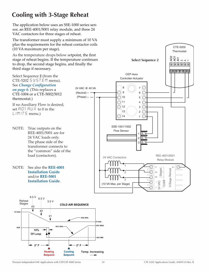
Cooling with 3-Stage Reheat
The application below uses an SSE-1000 series sen-sor, an REE-4001/5001 relay module, and three 24 VAC contactors for three stages of reheat.The transformer must supply a minimum of 10 VA plus the requirements for the reheat contactor coils (10 VA maximum per stage).As the temperature drops below setpoint, the first stage of reheat begins. If the temperature continues to drop, the second stage begins, and finally the third stage if necessary.
Select Sequence 2 (from the CTE-5202 SYSTEM menu). See Change Configuration on page 6. (This replaces a CTE-1004 or a CTE-5002/5012 thermostat.)If no Auxiliary Flow is desired, set AO1 AUX to 0 in the LIMITS menu.)
~TT
AI1
AO
1A
O2
CTE-5202
Thermostat
24 VAC @ 40 VA
~
–
(Phase)
(Neutral)
1
2
3
7
6
5
4
3
2
1
8
9
10
11
12
13
14
CEP-4xxx
Controller-Actuator
SSE-1001/1002
Flow Sensor
REE-4001/5001 Relay Module
~–
24 V
AC
32
1
Stag
es
3-St
age
Reh
eat T
24 VAC Contactors
(10 VA Max. per Stage)
2
1
3
Load
Select Sequence 2
NOTE: Triac outputs on the REE-4001/5001 are for 24 VAC loads only. The phase side of the transformer connects to the “common” side of the load (contactors).
NOTE: See also the REE-4001 Installation Guide and/or REE-5001 Installation Guide.
2° F
Of Loop10%
2° F
AO1 MAXAUX
AO1 MIN
COLD AIR SEQUENCE
0 Volts
12 Volts
Temp. IncreasingCoolingSetpoint
HeatingSetpoint
9.5 V
3.5 V
#3
#1
6.5 V
#2
Reheat Stages
AO2 (RA)
AO1 (DA)

Pressure Independent VAV Applications with CEP/CSP-4000 Series 35 CTE-5202 Applications Guide, AN0912A Rev. B
Cooling/Heating Changeover
~TT
AI1
AO
1A
O2
CTE-5202
Thermostat
24 VAC @ 10 VA
~
–
(Phase)
(Neutral)
7
6
5
4
3
2
1
8
9
10
11
12
13
14
CEP-4xxx
Controller-Actuator
SSE-2001/2002
Flow Sensor1
2
3
Y
X
Select Sequence 1
Using a duct sensor with the CTE-5202, an automatic changeover is provided for heating/cooling applica-tions. The duct sensor will switch the thermostat between cooling and heating modes based on the temperature of the duct supply air. A duct tempera-ture higher than changeover temperature, switches control to heating mode, and a temperature lower than changeover temperature, switches control to cooling mode.
Select Sequence 1 (from the CTE-5202 SYSTEM menu). See Change Configuration on page 6 and Hot/Cold Changeover on page 5. The default changeover temperature is 77° F, configurable from 55 to 85° F in the CTE-5202 ADVANCE menu.
NOTE: If replacing a CTE-1103 thermostat as described in the Cooling Heating Change-over section of the CEP-4000 Series Ap-plications Guide or a CTE-5001/5011 as described in the CTE-5001/5011 Installation Guide, the REE-1005 or REE-1014 relay module is not needed with the CTE-5202.
NOTE: Minimums can be set at zero air flow, but a minimum of greater than zero is required for a quick changeover.
NOTE: For an SSE-2001/2002 flow sensor, connect the X and Y terminals to the CTE-5202’s AI1 and Common terminals.
2° F 2° F 2° F
COLD AIR SEQUENCE
AO1 (DA)
Setpoint
AO1 MIN
HOT AIR SEQUENCE
AO1 (RA)
AO1 MAX AO1 MAX
AO1 MIN
Temp. Increasing
Setpoint

Pressure Independent VAV Applications with CEP/CSP-4000 Series 36 CTE-5202 Applications Guide, AN0912A Rev. B
Cooling with Proportional Hot Water Reheat
See Cooling with 3-Stage Reheat on page 34. This application operates similarly except for using a hot water valve instead of electric heating elements for reheat.AO1 controls airflow and AO2 controls the valve. When there is a call for heat, the thermostat modulates the hot water valve.The CTE-5202 here replaces a CTE-1004 (DA cooling and RA heating) and is used in conjunction with an REE-4006 time proportioning relay module and a (NC) VEP-12/22/34 series hot water valve. The REE-4006 relay is designed for time proportioning control of thermic electrical hot water valves.
NOTE: The VEP-12/22/34 series valves and REE-4006 relay module have been discontinued. Replacement actuators (MEP-3001s) for those valves are still available (as of Oct. 2012). The REE-4006 can be replaced by an REE-4106 or REE-5106, which have built-in power supplies that could be used to power the CTE-5202 if desired. See also use of a VEB-43/46 valve in Cooling with Hot Water Reheat on page 27.
2° F
Of Loop10%
2° F
AO1 MAXAUX
AO1 MIN
COLD AIR SEQUENCE
0 Volts
12 Volts
Temp. IncreasingCoolingSetpoint
HeatingSetpoint
Hot Water Reheat AO2 (RA)
AO1 (DA)
~TT
AI1
AO
1A
O2
CTE-5202
Thermostat
24 VAC @ 12 VA
~
–
(Phase)
(Neutral)
1
2
3
7
6
5
4
3
2
1
8
9
10
11
12
13
14
CEP-4xxx
Controller-Actuator
SSE-1001/1002
Flow Sensor
REE-4006/4106/5106
Relay Module
LOAD
9
C
T
(NC) VEP-12/22/34
Series Valve and
MEP-3000 Series
Thermic Actuator
~
–
SelectSequence 2
(See also the REE-4106 Installation Guide, REE-5106 Installation Guide, and the Cooling with Porportional Reheat section with a CTE-1004 in the CEP-4000 Series Applications Guide.)
Pressure Independent VAV Applications with CEP/CSP-4000 Series 37 CTE-5202 Applications Guide, AN0912A Rev. B
~TT
AI1
AO
1A
O2
CTE-5202
Thermostat
24 VAC @ 40 VA
~
–
(Phase)
(Neutral)
1
2
3
7
6
5
4
3
2
1
8
9
10
11
12
13
14
CEP-4xxx
Controller-Actuator
SSE-1001/1002
Flow Sensor
REE-4002/5002 Relay Module24 VAC Contactors
(10 VA Max. per Stage)
Heat Stage 1
Fan
~–
24 V
AC
Fan
12
Sta
ges
XT
Load
Heat Stage 2
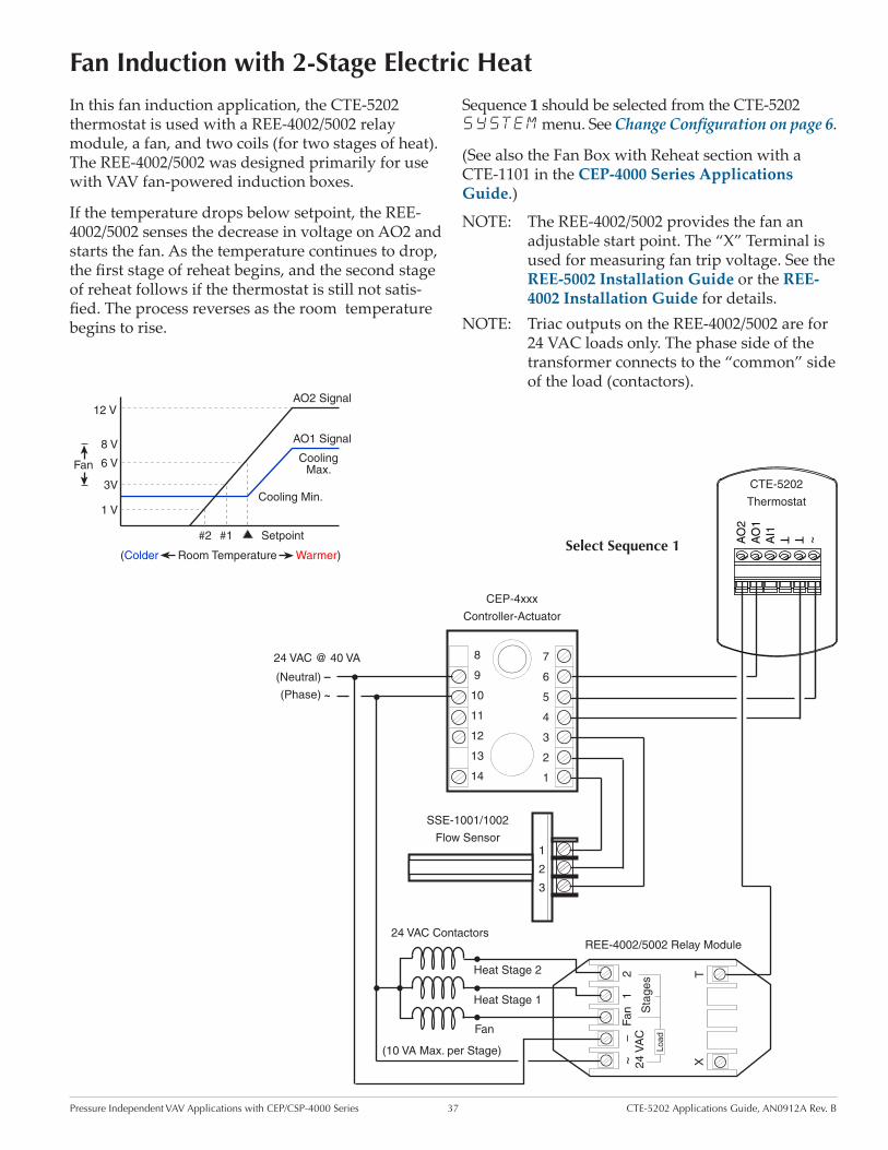
Fan Induction with 2-Stage Electric Heat
In this fan induction application, the CTE-5202 thermostat is used with a REE-4002/5002 relay module, a fan, and two coils (for two stages of heat). The REE-4002/5002 was designed primarily for use with VAV fan-powered induction boxes.
If the temperature drops below setpoint, the REE-4002/5002 senses the decrease in voltage on AO2 and starts the fan. As the temperature continues to drop, the first stage of reheat begins, and the second stage of reheat follows if the thermostat is still not satis-fied. The process reverses as the room temperature begins to rise.
Sequence 1 should be selected from the CTE-5202 SYSTEM menu. See Change Configuration on page 6.
(See also the Fan Box with Reheat section with a CTE-1101 in the CEP-4000 Series Applications Guide.)
NOTE: The REE-4002/5002 provides the fan an adjustable start point. The “X” Terminal is used for measuring fan trip voltage. See the REE-5002 Installation Guide or the REE-4002 Installation Guide for details.
NOTE: Triac outputs on the REE-4002/5002 are for 24 VAC loads only. The phase side of the transformer connects to the “common” side of the load (contactors).
Select Sequence 1
Fan
(Colder Room Temperature Warmer)
AO2 Signal
Cooling Max.
Cooling Min.
AO1 Signal
Setpoint
6 V
1 V
3V
#2 #1
12 V
8 V
Pressure Independent VAV Applications with CEP/CSP-4000 Series 38 CTE-5202 Applications Guide, AN0912A Rev. B
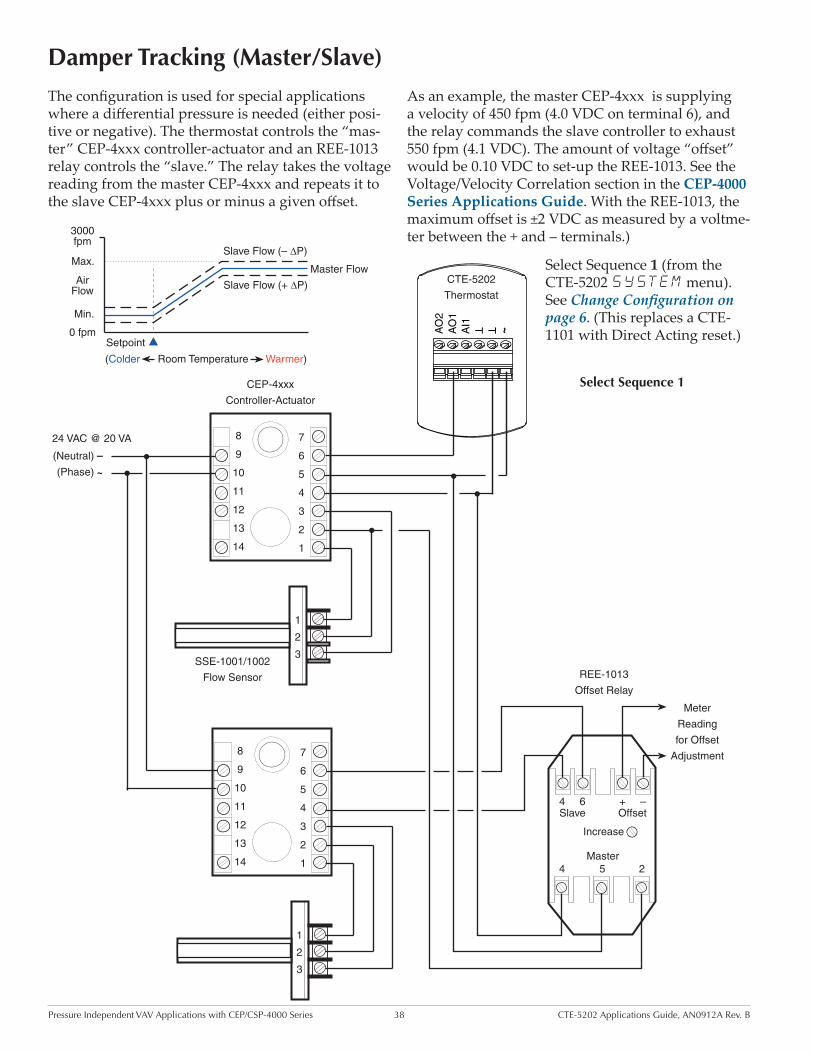
Damper Tracking (Master/Slave)
The configuration is used for special applications where a differential pressure is needed (either posi-tive or negative). The thermostat controls the “mas-ter” CEP-4xxx controller-actuator and an REE-1013 relay controls the “slave.” The relay takes the voltage reading from the master CEP-4xxx and repeats it to the slave CEP-4xxx plus or minus a given offset.
As an example, the master CEP-4xxx is supplying a velocity of 450 fpm (4.0 VDC on terminal 6), and the relay commands the slave controller to exhaust 550 fpm (4.1 VDC). The amount of voltage “offset” would be 0.10 VDC to set-up the REE-1013. See the Voltage/Velocity Correlation section in the CEP-4000 Series Applications Guide. With the REE-1013, the maximum offset is ±2 VDC as measured by a voltme-ter between the + and – terminals.)
Select Sequence 1 (from the CTE-5202 SYSTEM menu). See Change Configuration on page 6. (This replaces a CTE-1101 with Direct Acting reset.)
����
����
�������������
���� �����������������������������������
�������
�������
�����������
�����������������
�����������������
~TT
AI1
AO
1A
O2
CTE-5202
Thermostat
24 VAC @ 20 VA
~
–
(Phase)
(Neutral)
1
2
3
7
6
5
4
3
2
1
8
9
10
11
12
13
14
CEP-4xxx
Controller-Actuator
SSE-1001/1002
Flow Sensor
1
2
3
7
6
5
4
3
2
1
8
9
10
11
12
13
144 5
6Slave4
2
–
Increase
+Offset
Master
Meter
Reading
for Offset
Adjustment
REE-1013
Offset Relay
Select Sequence 1
Pressure Independent VAV Applications with CEP/CSP-4000 Series 39 CTE-5202 Applications Guide, AN0912A Rev. B
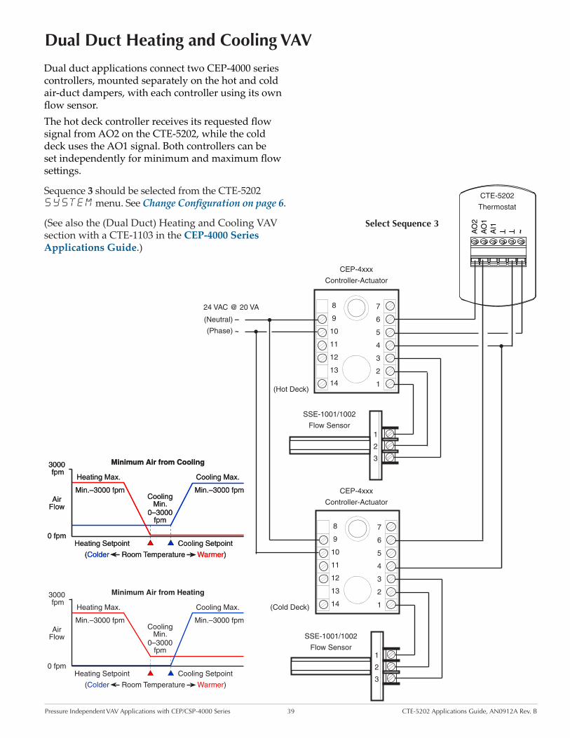
Dual Duct Heating and Cooling VAV
Dual duct applications connect two CEP-4000 series controllers, mounted separately on the hot and cold air-duct dampers, with each controller using its own flow sensor. The hot deck controller receives its requested flow signal from AO2 on the CTE-5202, while the cold deck uses the AO1 signal. Both controllers can be set independently for minimum and maximum flow settings.
Sequence 3 should be selected from the CTE-5202 SYSTEM menu. See Change Configuration on page 6.
(See also the (Dual Duct) Heating and Cooling VAV section with a CTE-1103 in the CEP-4000 Series Applications Guide.)
~TT
AI1
AO
1A
O2
CTE-5202
Thermostat
24 VAC @ 20 VA
~
–
(Phase)
(Neutral)
1
2
3
7
6
5
4
3
2
1
8
9
10
11
12
13
14
CEP-4xxx
Controller-Actuator
SSE-1001/1002
Flow Sensor
1
2
3
7
6
5
4
3
2
1
8
9
10
11
12
13
14
SSE-1001/1002
Flow Sensor
CEP-4xxx
Controller-Actuator
(Hot Deck)
(Cold Deck)
Select Sequence 3
Cooling Max.
Cooling Min.
0 fpm
(Colder Room Temperature Warmer)
3000 fpm
Air Flow
Min.–3000 fpm
0–3000 fpm
Heating Max.
Min.–3000 fpm
Cooling SetpointHeating Setpoint
Minimum Air from Cooling
Cooling Max.
Cooling Min.
0 fpm
(Colder Room Temperature Warmer)
3000 fpm
Air Flow
Min.–3000 fpm
0–3000 fpm
Heating Max.
Min.–3000 fpm
Cooling SetpointHeating Setpoint
Minimum Air from Cooling
Cooling Max.
Cooling Min.
0 fpm
(Colder Room Temperature Warmer)
3000 fpm
Air Flow
Min.–3000 fpm
0–3000 fpm
Heating Max.
Min.–3000 fpm
Cooling SetpointHeating Setpoint
Minimum Air from Heating
Pressure Independent VAV Applications with CEP/CSP-4000 Series 40 CTE-5202 Applications Guide, AN0912A Rev. B
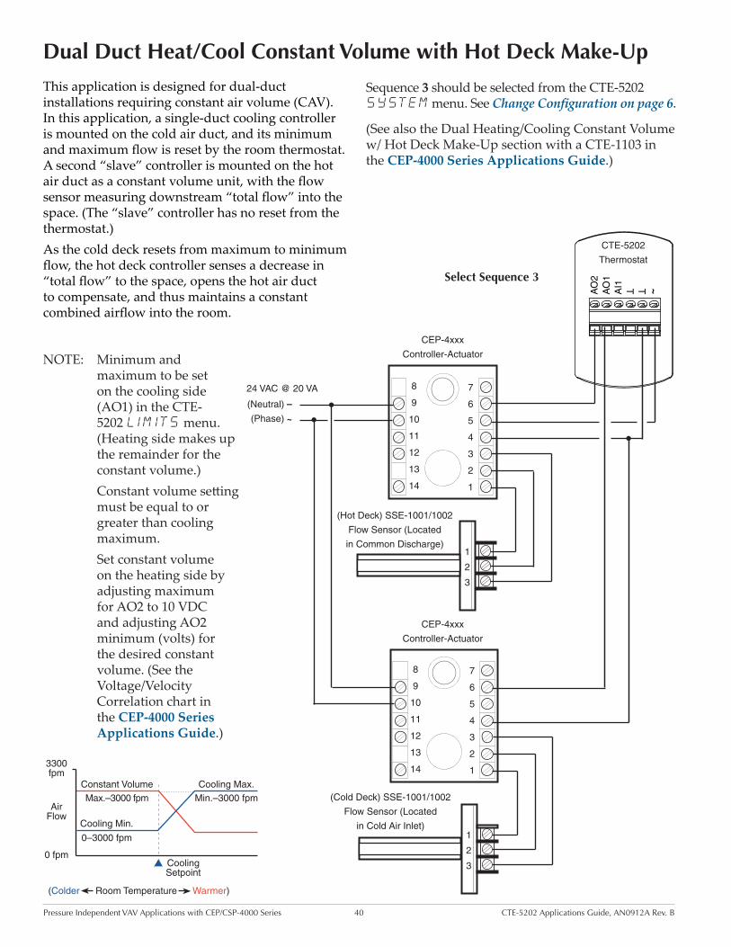
Dual Duct Heat/Cool Constant Volume with Hot Deck Make-Up
NOTE: Minimum and maximum to be set on the cooling side (AO1) in the CTE-5202 LIMITS menu. (Heating side makes up the remainder for the constant volume.)
Constant volume setting must be equal to or greater than cooling maximum.
Set constant volume on the heating side by adjusting maximum for AO2 to 10 VDC and adjusting AO2 minimum (volts) for the desired constant volume. (See the Voltage/Velocity Correlation chart in the CEP-4000 Series Applications Guide.)
This application is designed for dual-duct installations requiring constant air volume (CAV). In this application, a single-duct cooling controller is mounted on the cold air duct, and its minimum and maximum flow is reset by the room thermostat. A second “slave” controller is mounted on the hot air duct as a constant volume unit, with the flow sensor measuring downstream “total flow” into the space. (The “slave” controller has no reset from the thermostat.)As the cold deck resets from maximum to minimum flow, the hot deck controller senses a decrease in “total flow” to the space, opens the hot air duct to compensate, and thus maintains a constant combined airflow into the room.
�����
�����������������������������������������
�������
����������
���������
������������
�������
������������
����������
��������������������������
~TT
AI1
AO
1A
O2
CTE-5202
Thermostat
24 VAC @ 20 VA
~
–
(Phase)
(Neutral)
1
2
3
7
6
5
4
3
2
1
8
9
10
11
12
13
14
CEP-4xxx
Controller-Actuator
(Hot Deck) SSE-1001/1002
Flow Sensor (Located
in Common Discharge)
1
2
3
7
6
5
4
3
2
1
8
9
10
11
12
13
14
CEP-4xxx
Controller-Actuator
(Cold Deck) SSE-1001/1002
Flow Sensor (Located
in Cold Air Inlet)
Sequence 3 should be selected from the CTE-5202 SYSTEM menu. See Change Configuration on page 6.
(See also the Dual Heating/Cooling Constant Volume w/ Hot Deck Make-Up section with a CTE-1103 in the CEP-4000 Series Applications Guide.)
Select Sequence 3

Barber Colman TP-81xx Thermostats Replacement Applications 41 CTE-5202 Applications Guide, AN0912A Rev. B
Barber Colman TP-81xx Thermostats
Replacement Applications
This section gives sample applications for using the CTE-5202 in the place of a Barber Colman (TAC, Invensys, Schneider Electric) TP-81xx thermostat. Some of the applications include use with MP-52xx “beer can” actuators.
TP-8101, TP-8102, and TP-8103 Leads
and TerminalsFunction CTE-5202 Terminals
Red Wire Lead +20 VDC ~ (Phase)
Yellow Wire LeadProportional
OutputAO1
Blue Wire Lead Common
T
(Common)
Terminal 1 Common
T
(Common)
Terminal 2 Auxiliary Input AI1
NOTE: Use Sequence 1. See sample applications on page 42 and page 43.
TP-8124 and TP-8125 Terminals
FunctionCTE-5202 Terminals
OP2 2–15 VDC Cooling (DA) AO1
+20 +20 VDC (Input) ~ (Phase)
OP1 15–2 VDC Heating (RA) AO2
Com Common
T
(Common)
NOTE: Use Sequence 3. See sample applications on page 44 and page 45.
Barber Colman TP-81xx Thermostats Replacement Applications 42 CTE-5202 Applications Guide, AN0912A Rev. B
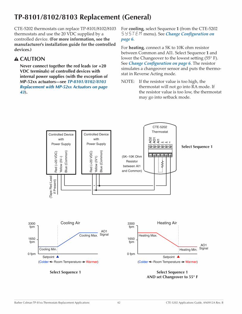
TP-8101/8102/8103 Replacement (General)
Select Sequence 1
CTE-5202 thermostats can replace TP-8101/8102/8103 thermostats and use the 20 VDC supplied by a controlled device. (For more information, see the manufacturer’s installation guide for the controlled devices.)
CAUTIONNever connect together the red leads (or +20 VDC terminals) of controlled devices with internal power supplies (with the exception of MP-52xx actuators—see TP-8101/8102/8103 Replacement with MP-52xx Actuators on page 43).
Heating Air
Heating Max.
Heating Min.
1650 fpm
0 fpmSetpoint
(Colder Room Temperature Warmer)
3300 fpm
Cooling Max.
Cooling Min.
1650 fpm
0 fpmSetpoint
(Colder Room Temperature Warmer)
3300 fpm
AO1 Signal
Cooling Air
AO1 Signal
Select Sequence 1 Select Sequence 1AND set Changeover to 55° F
For cooling, select Sequence 1 (from the CTE-5202 SYSTEM menu). See Change Configuration on page 6.
For heating, connect a 5K to 10K ohm resistor between Common and AI1. Select Sequence 1 and lower the Changeover to the lowest setting (55° F). See Change Configuration on page 6. The resistor simulates a changeover sensor and puts the thermo-stat in Reverse Acting mode.
NOTE: If the resistor value is too high, the thermostat will not go into RA mode. If the resistor value is too low, the thermostat may go into setback mode.
~TT
AI1
AO
1A
O2
CTE-5202
Thermostat
Red
(+
20 V
DC
)
(5K–10K Ohm
Resistor
between AI1
and Common)
Controlled Device
with
Power Supply
Yello
w (
IV1)
Blu
e (C
omm
on)
Red
(+
20 V
DC
)
Controlled Device
with
Power Supply
Yello
w (
IV–)
Blu
e (C
omm
on)
(Tap
e R
ed L
ead
if P
rese
nt)
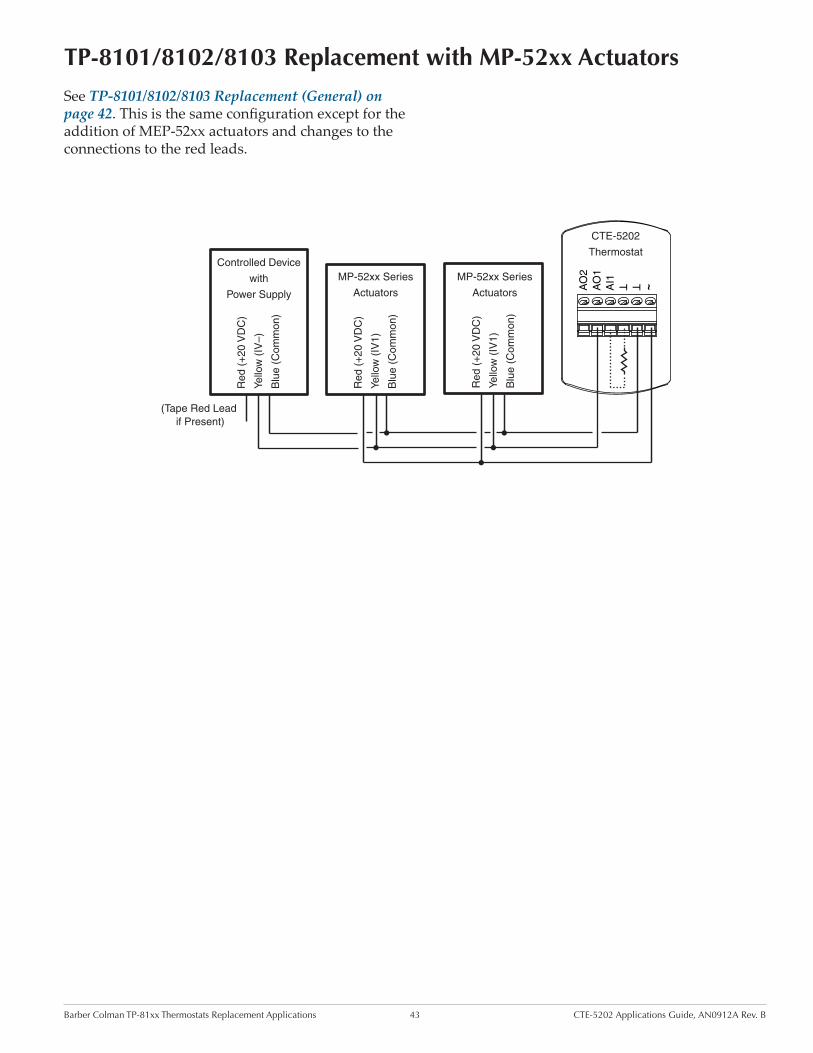
Barber Colman TP-81xx Thermostats Replacement Applications 43 CTE-5202 Applications Guide, AN0912A Rev. B
TP-8101/8102/8103 Replacement with MP-52xx Actuators
~TT
AI1
AO
1A
O2
CTE-5202
Thermostat
Red
(+
20 V
DC
)
Yello
w (
IV1)
Blu
e (C
omm
on)
Red
(+
20 V
DC
)
MP-52xx Series
Actuators
Yello
w (
IV1)
Blu
e (C
omm
on)
(Tape Red Lead if Present)
Red
(+
20 V
DC
)
Controlled Device
with
Power Supply
Yello
w (
IV–)
Blu
e (C
omm
on)
MP-52xx Series
Actuators
See TP-8101/8102/8103 Replacement (General) on page 42. This is the same configuration except for the addition of MEP-52xx actuators and changes to the connections to the red leads.

Barber Colman TP-81xx Thermostats Replacement Applications 44 CTE-5202 Applications Guide, AN0912A Rev. B
TP-8124/8125 Replacement with One or No MP-52xx Actuators
SelectSequence
3
~TT
AI1
AO
1A
O2
CTE-5202
Thermostat
Red
(+
20 V
DC
)
Yello
w (
IV1)
Blu
e (C
omm
on)
(Tape Red Leads if Present)
Red
(+
20 V
DC
)
Controlled Device
with
Power Supply
Yello
w (
IV1)
Blu
e (C
omm
on)
Red
(+
20 V
DC
)
Controlled Device
with
Power Supply
Yello
w (
IV–)
Blu
e (C
omm
on)
MP-52xx Series
Actuator (or Other
Controlled Device
with Power Supply)
Red
(+
20 V
DC
)
Controlled Device
with
Power Supply
Yello
w (
IV–)
Blu
e (C
omm
on)
(Tape Red Leads if Present)
CTE-5202 thermostats can replace TP-8101/8102/8103 thermostats and use the 20 VDC supplied by a controlled device. (For more information, see the manufacturer’s installation guide for the controlled devices.)
CAUTIONNever connect together the red leads (or +20 VDC terminals) of controlled devices with internal power supplies (with the exception of MP-52xx actuators).
AO2 MAX
AO2 MIN
AO2 (RA)AO1 (DA)
AO1 MIN
AO1 MAX
CoolingSetpoint
HeatingSetpoint
Temp.Increasing
2° F 2° F
Select Sequence 3 (from the CTE-5202 SYSTEM menu). See Change Configuration on page 6.
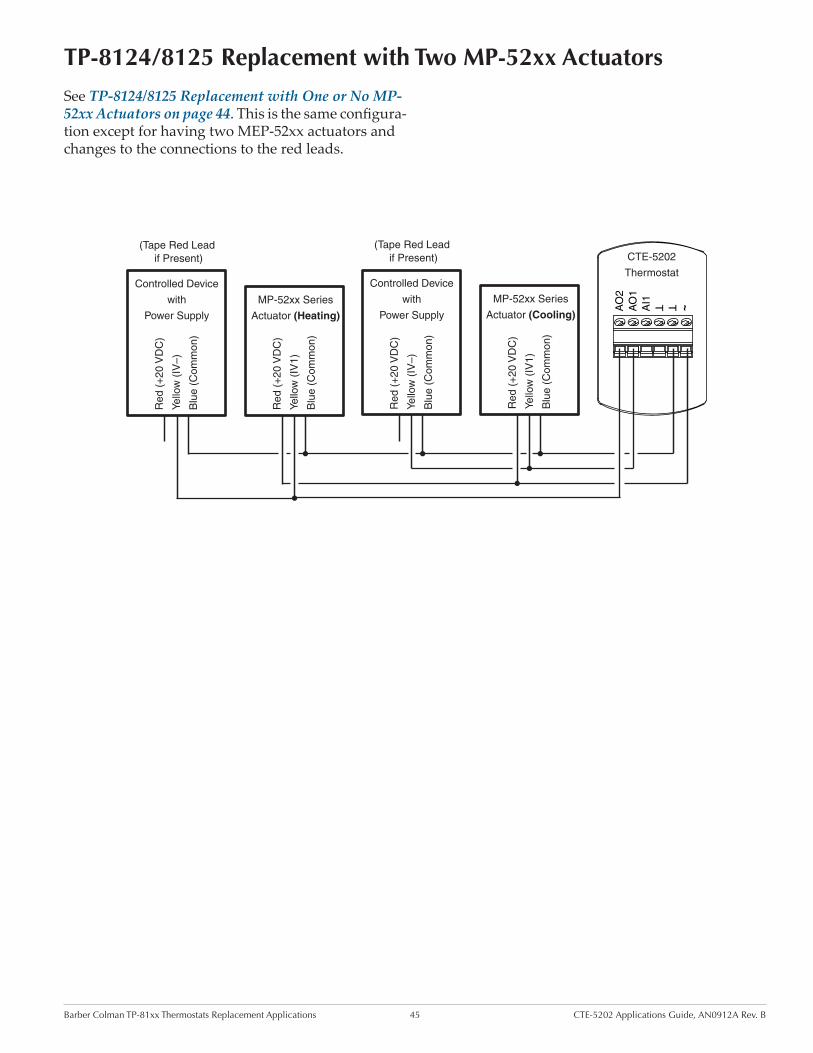
Barber Colman TP-81xx Thermostats Replacement Applications 45 CTE-5202 Applications Guide, AN0912A Rev. B
TP-8124/8125 Replacement with Two MP-52xx Actuators
~TT
AI1
AO
1A
O2
CTE-5202
Thermostat
Red
(+
20 V
DC
)
Yello
w (
IV1)
Blu
e (C
omm
on)
(Tape Red Lead if Present)
Red
(+
20 V
DC
)
Controlled Device
with
Power Supply
Yello
w (
IV–)
Blu
e (C
omm
on)
MP-52xx Series
Actuator (Cooling)
Red
(+
20 V
DC
)
Controlled Device
with
Power Supply
Yello
w (
IV–)
Blu
e (C
omm
on)
(Tape Red Lead if Present)
Red
(+
20 V
DC
)
Yello
w (
IV1)
Blu
e (C
omm
on)
MP-52xx Series
Actuator (Heating)
See TP-8124/8125 Replacement with One or No MP-52xx Actuators on page 44. This is the same configura-tion except for having two MEP-52xx actuators and changes to the connections to the red leads.

CTE-5202 Analog Electronic Thermostat w/ LCD Display 46 Applications Guide, AN0912A Rev. B
IndexSymbols
9.1 VDC vs. 24 VAC Power: 31
A
Accessories: 4Actuator
MEP-4002: 16MP-52xx “Beer Can”: 41
Advanced Features Menu: 6AI1, AO1, AO2: 5Auto and Override: 18, 21
B
Barber Colman TP-81xx: 41Baseboard: 11Blanking, Display: 6
C
CAV (Constant Air Volume): 40CEP-4000 Series: 30Changeover: 5, 15, 24, 25, 26, 35Chilled Beam
2-Pipe Heating and Cooling with Changeover: 154-Pipe Heating and Cooling: 14Cooling: 13
Cold Deck: 39, 40Configuration: 6Constant Volume: 39, 40Cooling: 13, 17, 20, 32Cooling and 3-Stage Reheat: 22Cooling/Heating Changeover: 15, 24, 25, 26, 35Cooling or Heating: 17, 20Cooling with 3-Stage Reheat: 34Cooling with 3-Stage Reheat and Night Setback/Setup:
23Cooling with Heating Changeover: 24Cooling with Heating Changeover and Electric Re-
heat: 25Cooling with Heating Changeover and Hot Water
Reheat: 26Cooling with Hot Water Reheat: 27Cooling with Morning Warm-Up: 33Cooling with Proportional Hot Water Reheat: 36C or F Temperature Scale: 6Cross-Reference
Barber Colman TP-81xx: 8, 41KMC CTE-1x0x: 8KMC CTE-50xx: 9KMC CTE-510x: 9Other Thermostats: 9
CSP-4000 Series: 30CSP-5001/5002: 19CTE-1x0x Cross-Reference: 8CTE-50xx Cross-Reference: 9CTE-510x Cross-Reference: 9CTE-1001 Replacement: 32CTE-1004 Replacement: 34, 36CTE-1101 Replacement: 32, 37, 38CTE-1103 Replacement: 35, 39, 40CTE-5001/5011 Replacement: 32, 35CTE-5002/5012 Replacement: 34CTE-5006/5016 Replacement: 22CTE-5015 Replacement: 20CTE-5101 Replacement: 9, 20, 21, 28CTE-5102 Replacement: 9, 20CTE-5103 Replacement: 9, 22, 24, 25, 26, 29CTE-5104 Replacement: 9, 22, 23, 27CTE-5105 Replacement: 9
D
Damper Tracking (Master/Slave): 38Deadband: 6Differential: 6Display
Blanking: 10Troubleshooting: 10
Dual DuctHeat/Cool Constant Volume with Hot Deck Make-
Up: 40Heating and Cooling VAV: 39Minimum Air from Cold Duct: 29
DuctDual: 29, 39, 40Single: 17, 20, 32
F
Fan Induction with 2-Stage Electric Heat: 28, 37Flow Sensors: 30F or C Temperature Scale: 6
H
Heating and Cooling VAV: 39Heating/Cooling Constant Volume w/ Hot Deck Make-
Up: 40Heating, RA and DA: 12, 17, 20Hot Deck: 39, 40

CTE-5202 Analog Electronic Thermostat w/ LCD Display 47 Applications Guide, AN0912A Rev. B© 2013 KMC Controls, Inc. AN0912A Rev. B
KMC Controls19476 Industrial DriveNew Paris, IN 46553
574.831.5250; Fax 574.831.5252www.kmccontrols.com; [email protected]
I
Important Notices: 4Input: 5Integral: 6Invensys TP-81xx: 41
L
Limits: 6Loop
Integral Time: 6Proportional Band: 6
M
Master/Slave: 38MEP-4002: 16Minimum Setpoint Differential: 6Morning Warm-Up: 5, 7, 25, 26, 33MP-52xx “Beer Can” Actuators: 41, 43, 44, 45
O
Offset: 6Operation: 5Outputs: 5
P
Pressure Dependent VAV: 16Pressure Independent VAV: 19, 30Proportional Band: 6
R
RA and DA Heating: 12REE-1013: 38REE-4001: 34REE-4002: 37REE-4006: 36REE-4106: 36REE-5001: 22, 23, 25, 34REE-5002: 28, 37REE-5106: 36
S
Schneider Electric TP-81xx: 41Sequences: 6, 7Setback: 5Setpoint
Adjusting: 6Troubleshooting: 10
Single Duct: 16, 19, 32Span: 6SSE-2001/2002 Flow Sensor: 33, 35Standby (Setback): 5STE-140x Duct Sensor: 24, 25, 26STE-1454/1455 Sensor: 15Support Files: 3System Menu: 6
T
TAC TP-81xx: 41Temperature
Offset: 6Scale (F or C): 6Troubleshooting: 10
TP-81xx Thermostats Cross-Reference: 41TP-8101/8102/8103 Replacement: 42, 43TP-8124/8125 Replacement: 44, 45Troubleshooting: 10TTE-2001 Duct Sensor/Transmitter: 24, 25, 26
U
Unoccupied: 5
V
Valve: 12, 13, 14, 15, 26, 27, 36VAV (Variable Air Volume)
Pressure Dependent: 16Pressure Independent: 19, 30
VEB-43/46 Series: 12, 13, 14, 15, 26, 27VEP-12/22/34 Series: 36
W
Warm-Up. See Morning Warm-UpWeb Site: 3Wiring: 10