applications - wgflow.com seal shaft sealing with choices between gland packing, ... discharge...
TRANSCRIPT


3
SP PUMPS
Applications
Handling of waste water and untreated sewage, in sewage treatment, industry, power plants and refinery. Unscreened sewage. Excavations and quarries. Industrial wastes. Sludge and viscous liquids. Food processing and breweries. Liquid with large solids and stringy materials.
Operating data
Impeller typesDC - K V SC
Capacity Q up to6000 500 250 m3/h
1700 140 70 l/sec
Head H up to 100 60 20 m
Operating pressure P up to 10 10 10 bar
Mediatemperature t up to 70 70 70 ˚C
Shaft seal
Shaft sealing with choices between gland packing, mechanical seal or double mechanical seal.
Standard materials
Pump casing: Cast iron (JL 1040)Stuffing Box: Cast iron (JL 1040)Impeller: Cast iron (JL 1040)Shaft: CK 60Casing wear ring: Cast iron (JL 1040)Gland Packing / Mechanical seal / Double mechanical seal
Designation
SP VW DC 100 400
Pump typeMounting typeImpeller typeDN - dischargenozzle diameter [mm]Nominal impellerdiameter [mm]
Mounting types: H (standard, belt-type), VD, VD-MSL, VW (see below)Impeller types: DC, K, SC, V (see below)Discharge nozzle & impeller nominal diameters: See below for wide range
Design
Horizontally or vertically mounted, volute casing pump. Dry or wet installation. Single-vane (SC), Multi-vane (DC & K), or Vortex (V) impellers.
Design features
• Simple mounting. No foundation required.• No stuffing box for VW installation type.• Automatic operation with float switches.• Robust construction.• Volute casing.• Easy cleaning through suction and volute cleaning holes.• Standardized for max parts interchangeability.• Small horizontal space requirement and motor protection against flooding of the dry pit.
Bearings
Self-media, clean water, grease or oil lubrication for the rolling bearings, radial and/or thrust bearings
depending on the design.
4
SP PUMPS
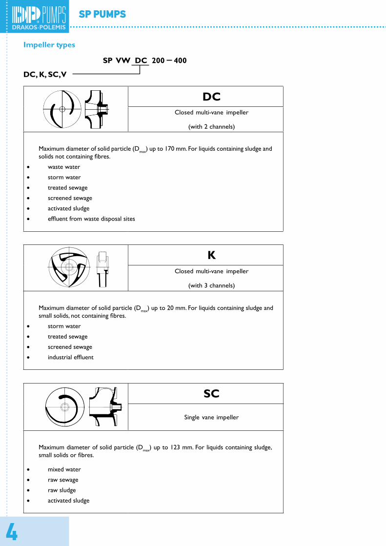
Impeller types
SP VW DC 200 400
DC, K, SC, V
DCClosed multi-vane impeller
(with 2 channels)
Maximum diameter of solid particle (Dmax) up to 170 mm. For liquids containing sludge andsolids not containing fibres.
• waste water
• storm water
• treated sewage
• screened sewage
• activated sludge
• effluent from waste disposal sites
KClosed multi-vane impeller
(with 3 channels)
Maximum diameter of solid particle (Dmax) up to 20 mm. For liquids containing sludge andsmall solids, not containing fibres.
• storm water
• treated sewage
• screened sewage
• industrial effluent
SC
Single vane impeller
Maximum diameter of solid particle (Dmax) up to 123 mm. For liquids containing sludge,small solids or fibres.
• mixed water
• raw sewage
• raw sludge
• activated sludge
5
SP PUMPS
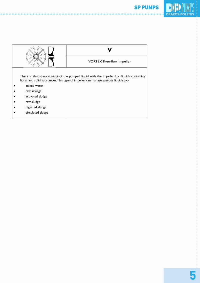
V
VORTEX Free-flow impeller
There is almost no contact of the pumped liquid with the impeller. For liquids containingfibres and solid substances. This type of impeller can manage gaseous liquids too.
• mixed water
•raw sewage
•activated sludge
•raw sludge
•digested sludge
•circulated sludge
6
SP PUMPS
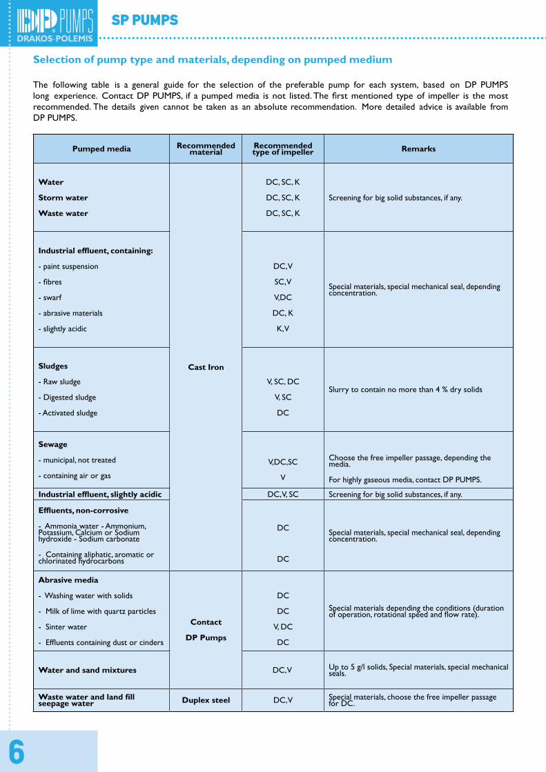
Selection of pump type and materials, depending on pumped medium
The following table is a general guide for the selection of the preferable pump for each system, based on DP PUMPS long experience. Contact DP PUMPS, if a pumped media is not listed. The first mentioned type of impeller is the most recommended. The details given cannot be taken as an absolute recommendation. More detailed advice is available from DP PUMPS.
Pumped media Recommendedmaterial
Recommendedtype of impeller Remarks
Water
Storm water
Waste water
Cast Iron
DC, SC, K
DC, SC, K
DC, SC, K
Screening for big solid substances, if any.
Industrial effluent, containing:
- paint suspension
- fibres
- swarf
- abrasive materials
- slightly acidic
DC, V
SC, V
V,DC
DC, K
K, V
Special materials, special mechanical seal, dependingconcentration.
Sludges
- Raw sludge
- Digested sludge
- Activated sludge
V, SC, DC
V, SC
DC
Slurry to contain no more than 4 % dry solids
Sewage
- municipal, not treated
- containing air or gas
V,DC,SC
V
Choose the free impeller passage, depending themedia.
For highly gaseous media, contact DP PUMPS.
Industrial effluent, slightly acidic DC, V, SC Screening for big solid substances, if any.
Effluents, non-corrosive
- Ammonia water - Ammonium, Potassium, Calcium or Sodiumhydroxide - Sodium carbonate
- Containing aliphatic, aromatic orchlorinated hydrocarbons
DC
DC
Special materials, special mechanical seal, dependingconcentration.
Abrasive media
- Washing water with solids
- Milk of lime with quartz particles
- Sinter water
- Effluents containing dust or cinders
Contact
DP Pumps
DC
DC
V, DC
DC
Special materials depending the conditions (durationof operation, rotational speed and flow rate).
Water and sand mixtures DC, V Up to 5 g/l solids, Special materials, special mechanicalseals.
Waste water and land fillseepage water Duplex steel DC, V Special materials, choose the free impeller passage
for DC.
7
SP PUMPS
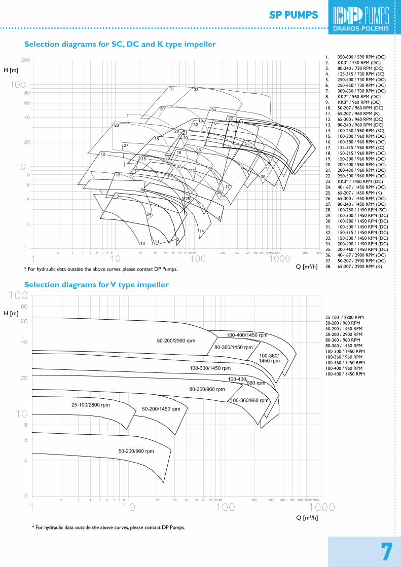
Selection diagrams for SC, DC and K type impeller
* For hydraulic data outside the above curves, please contact DP Pumps.
Selection diagrams for V type impeller
* For hydraulic data outside the above curves, please contact DP Pumps.
1. 350-800 / 590 RPM (DC)2. KK3” / 730 RPM (DC)3. 80-240 / 730 RPM (DC)4. 125-315 / 730 RPM (SC)5. 250-500 / 730 RPM (DC)6. 250-650 / 730 RPM (DC)7. 300-630 / 730 RPM (DC)8. KK2” / 960 RPM (DC)9. KK3” / 960 RPM (DC)10. 50-207 / 960 RPM (DC)11. 65-207 / 960 RPM (K)12. 65-300 / 960 RPM (DC)13. 80-240 / 960 RPM (DC)14. 100-250 / 960 RPM (SC)15. 100-300 / 960 RPM (DC)16. 100-380 / 960 RPM (DC)17. 125-315 / 960 RPM (SC)18. 150-315 / 960 RPM (DC)19. 150-500 / 960 RPM (DC)20. 200-400 / 960 RPM (DC)21. 200-430 / 960 RPM (DC)22. 250-500 / 960 RPM (DC)23. KK3” / 1450 RPM (DC)24. 40-167 / 1450 RPM (DC)25. 65-207 / 1450 RPM (K)26. 65-300 / 1450 RPM (DC)27. 80-240 / 1450 RPM (DC)28. 100-250 / 1450 RPM (SC)29. 100-300 / 1450 RPM (DC)30. 100-380 / 1450 RPM (DC)31. 100-500 / 1450 RPM (DC)32. 150-315 / 1450 RPM (DC)33. 150-500 / 1450 RPM (DC)34. 200-400 / 1450 RPM (DC)35. 200-460 / 1450 RPM (DC)36. 40-167 / 2900 RPM (DC)37. 50-207 / 2900 RPM (DC)38. 65-207 / 2900 RPM (K)
25-100 / 2800 RPM50-200 / 960 RPM50-200 / 1450 RPM50-200 / 2900 RPM80-360 / 960 RPM80-360 / 1450 RPM100-300 / 1450 RPM100-360 / 960 RPM100-360 / 1450 RPM 100-400 / 960 RPM100-400 / 1450 RPM
H [m]
Q [m3/h]
Q [m3/h]
H [m]
8
SP PUMPS
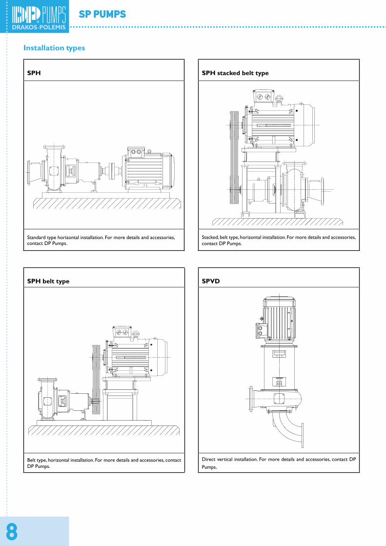
Installation types
SPH SPH stacked belt type
Standard type horizontal installation. For more details and accessories, contact DP Pumps.
Stacked, belt type, horizontal installation. For more details and accessories,contact DP Pumps.
SPH belt type SPVD
Belt type, horizontal installation. For more details and accessories, contactDP Pumps.
Direct vertical installation. For more details and accessories, contact DPPumps.
9
SP PUMPS
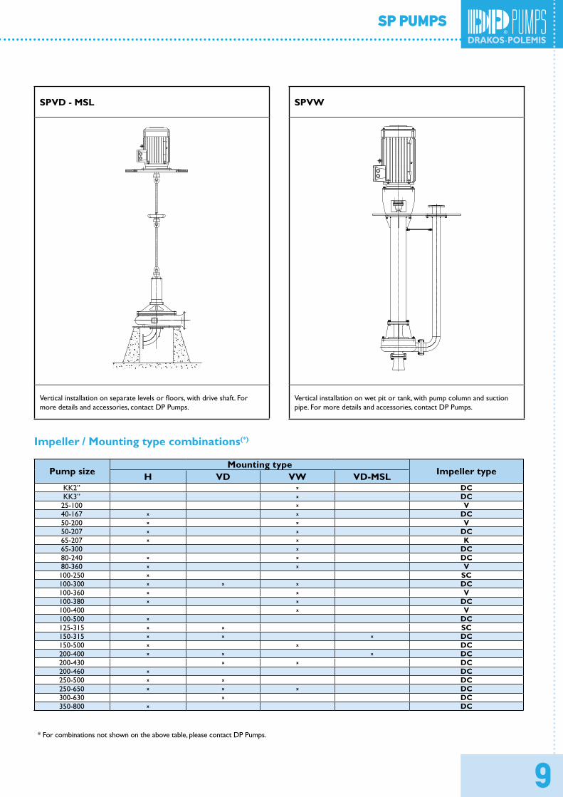
SPVD - MSL SPVW
Vertical installation on separate levels or floors, with drive shaft. For more details and accessories, contact DP Pumps.
Vertical installation on wet pit or tank, with pump column and suction pipe. For more details and accessories, contact DP Pumps.
Impeller / Mounting type combinations(*)
Pump sizeMounting type
Impeller typeH VD VW VD-MSLKK2“ x DCKK3“ x DC
25-100 x V40-167 x x DC50-200 x x V50-207 x x DC65-207 x x K65-300 x DC80-240 x x DC80-360 x x V100-250 x SC100-300 x x x DC100-360 x x V100-380 x x DC100-400 x V100-500 x DC125-315 x x SC150-315 x x x DC150-500 x x DC200-400 x x x DC200-430 x x DC200-460 x DC250-500 x x DC250-650 x x x DC300-630 x DC350-800 x DC
* For combinations not shown on the above table, please contact DP Pumps.
10
SP PUMPS
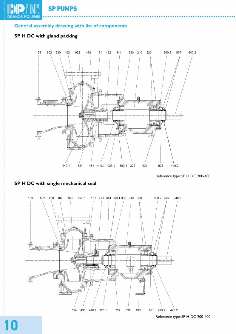
General assembly drawing with list of components
SP H DC with gland packing
SP H DC with single mechanical seal
Reference type: SP H DC 200-400
Reference type: SP H DC 200-400
11
SP PUMPS
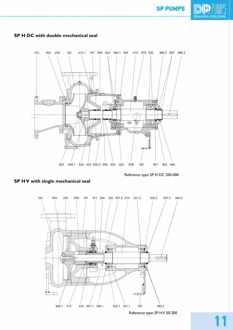
SP H DC with double mechanical seal
SP H V with single mechanical sealReference type: SP H DC 200-400
Reference type: SP H V 50-200
12
SP PUMPS
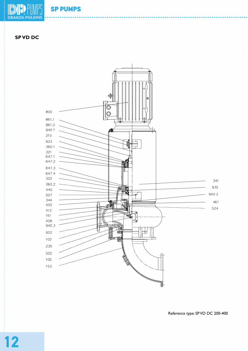
SP VD DC
Reference type: SP VD DC 200-400
13
SP PUMPS
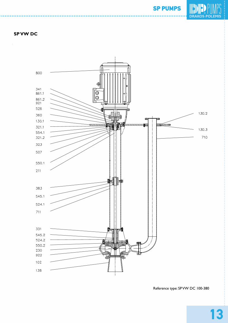
SP VW DC
Reference type: SP VW DC 100-380
14
SP PUMPS
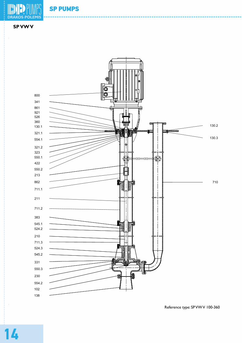
SP VW V
Reference type: SP VW V 100-360

15
SP PUMPS
List of components with standard versions of materials
Part number to VDMA Part name Standard material of construction102 Pump casing Cast Iron GG - 20105 Pump casing part Steel St 37.2130 Housing part Steel St 37.2138 Suction bell Cast Iron GG - 20153 Suction Cast Iron GG - 20161 Housing cover Cast Iron GG - 20183 Support foot Steel St 37.2210 Shaft CK 60211 Pump shaft Stainless steel SS AISI 420213 Headshaft Stainless steel SS AISI 420230 Impeller Cast Iron GG - 20320 Angular contact ball bearing ---321 Grooved ball bearing ---322 Cylindrical roller bearing ---323 Thrust ball bearing ---330 Bearing housing Cast Iron GG - 20331 Bearing housing Cast Iron GG - 20341 Motor stool Cast Iron GG - 20344 Pump casing part Cast Iron GG - 20360 Bearing cover Cast Iron GG - 20383 Bearing retainer Cast Iron GG - 20412 O-ring Rubber422 Felt ring ---433 Mechanical seal ---440 Shaft sealing part CuSn12452 Stuffing box gland Cast Iron GG - 20458 Locking ring CuSn12461 Stuffing box packing Teflon471 Seal cover Cast Iron GG - 20502 Bowl wear ring Cast Iron GG - 20507 Thrower ring Rubber524 Shaft sleeve Stainless steel SS AISI 420526 Ball bearing ring Stainless steel SS AISI 420545 Bush bearing CuSn12550 Distance ring Stainless steel SS AISI 420554 Washer Stainless steel SS AISI 420638 Oil level regulator ---647 Grease regulator ---672 Breather ---710 Pipe Steel St 37.2711 Column Pipe Steel St 37.2800 Electric Motor ---861 Motor coupling Cast Iron GG - 20862 Pump coupling Cast Iron GG - 20921 Adjusting Nut CuSn12922 Impeller nut CK 60923 Bearing nut St931 Locking plate St932 Circlip F.St940 Key St
Material cross reference
DIN Designation DIN Number USA DesignationGG – 20 0.6020 A48 Class 30X20Cr13 1.4021 AISI 420
Ck35 1.1181 AISI 1035Ck45 1.1191 AISI 1045St 35 1.0308
St 60-2 1.0543 St 70-2 1.0633 St 37-2 1.0112
USt 37-2 1.0036 A 570 Gr 33.36Rg 5 (CuSn5 ZnPb) 2.1096.01 SAE 40Rg 7 (CuSn7 ZnPb) 2.1090.01 SAE 660

16
SP PUMPS
Installation dimensions
NA type bearing bracket Discharge output types
LDP type bearing bracket
Pump size Bearing
bracket size/type
Dimensions to mmPump Mounting End shaft
NWS e NWD a f1 h1 h2 g b m1 m2 v1 v2 v3 n1 n2 s1 d1 l1 t u
40-167 16/LDP 65 - 40 80 360 132 160 - 50 100 70 - - - 240 190
15
24 50 27 850-200 32/LDP 50 -
5060 530 180 215 - 60 - - 20 22 60 320 250 32 87 35 10
50-20722/LDP
65 -100 360
160 200 - 50 100 70 - - - 265 21224 50 27 8
65-207 80 - 65 180 225 - 65 125 95 - - - 320 25080-240 32/LDP
10010
80255 502 200
300- 80 160 120 - - - 360 200 18 32 87 35 10
80-360 55/NA - 120 738 270 180 100 200 150 - - - 480 380 25 55 110 59 16100-250 32/LDP
125 12.5
100
343 532 225 250 - 70 - - 30 93 70 320 23018
32 87 35 10100-300 42/LDP
310568
250 285 175 80 160 120- - -
400 31542 116 45 12
100-300
55/NA
733 - - -
55110
59 16100-360 150 - 147 794
280310 180 77.5 210
150- - - 505 450 23
100-380 12512.5
320 706 300 223 100200
- - - 500 40025
100-500150
333 695 355 380 277 150 - - - 625 475 134125-315
42/LDP125 375 604 265 320 -
80- -
30105
80400
32018
42 116 45 12150-315
20025
150
381 596280 405
- - -50 420 23
150-315 55/NA 380 743 - - - 55 110 59 16150-500
75/NA32.5 360 890 400 400 290 150 300 240 - - - 700 550
25
75140
80 20150-500S
250
25
435 903 350 470 - 125 250 200 - - -
625 500
138200-400 55/NA
200 425743
320 400 228150 - -
30 48 12555 110 59 16
200-40075/NA 200
920 125- -
75
139
80 20200-400S - - 135200-460 150 445 945 400 450 256 150 300 240 - - - 700 550
140250-500300 35 250
470 935 420 470 306160
- - 30 50 150 800 640250-650 450 915 500 600 370 400 320 - - - 1000 840350-800 90/NA 350 40 350 497 1100 600 750 460 250 500 420 - - - 1150 900 30 90 170 95.5 22
type I - centered type II - offset (g=0)
17
SP PUMPS
Installation dimensions
NA type bearing bracket Discharge output types
LDP type bearing bracket
Pump size Bearing
bracket size/type
Dimensions to mmPump Mounting End shaft
NWS e NWD a f1 h1 h2 g b m1 m2 v1 v2 v3 n1 n2 s1 d1 l1 t u
40-167 16/LDP 65 - 40 80 360 132 160 - 50 100 70 - - - 240 190
15
24 50 27 850-200 32/LDP 50 -
5060 530 180 215 - 60 - - 20 22 60 320 250 32 87 35 10
50-20722/LDP
65 -100 360
160 200 - 50 100 70 - - - 265 21224 50 27 8
65-207 80 - 65 180 225 - 65 125 95 - - - 320 25080-240 32/LDP
10010
80255 502 200
300- 80 160 120 - - - 360 200 18 32 87 35 10
80-360 55/NA - 120 738 270 180 100 200 150 - - - 480 380 25 55 110 59 16100-250 32/LDP
125 12.5
100
343 532 225 250 - 70 - - 30 93 70 320 23018
32 87 35 10100-300 42/LDP
310568
250 285 175 80 160 120- - -
400 31542 116 45 12
100-300
55/NA
733 - - -
55110
59 16100-360 150 - 147 794
280310 180 77.5 210
150- - - 505 450 23
100-380 12512.5
320 706 300 223 100200
- - - 500 40025
100-500150
333 695 355 380 277 150 - - - 625 475 134125-315
42/LDP125 375 604 265 320 -
80- -
30105
80400
32018
42 116 45 12150-315
20025
150
381 596280 405
- - -50 420 23
150-315 55/NA 380 743 - - - 55 110 59 16150-500
75/NA32.5 360 890 400 400 290 150 300 240 - - - 700 550
25
75140
80 20150-500S
250
25
435 903 350 470 - 125 250 200 - - -
625 500
138200-400 55/NA
200 425743
320 400 228150 - -
30 48 12555 110 59 16
200-40075/NA 200
920 125- -
75
139
80 20200-400S - - 135200-460 150 445 945 400 450 256 150 300 240 - - - 700 550
140250-500300 35 250
470 935 420 470 306160
- - 30 50 150 800 640250-650 450 915 500 600 370 400 320 - - - 1000 840350-800 90/NA 350 40 350 497 1100 600 750 460 250 500 420 - - - 1150 900 30 90 170 95.5 22
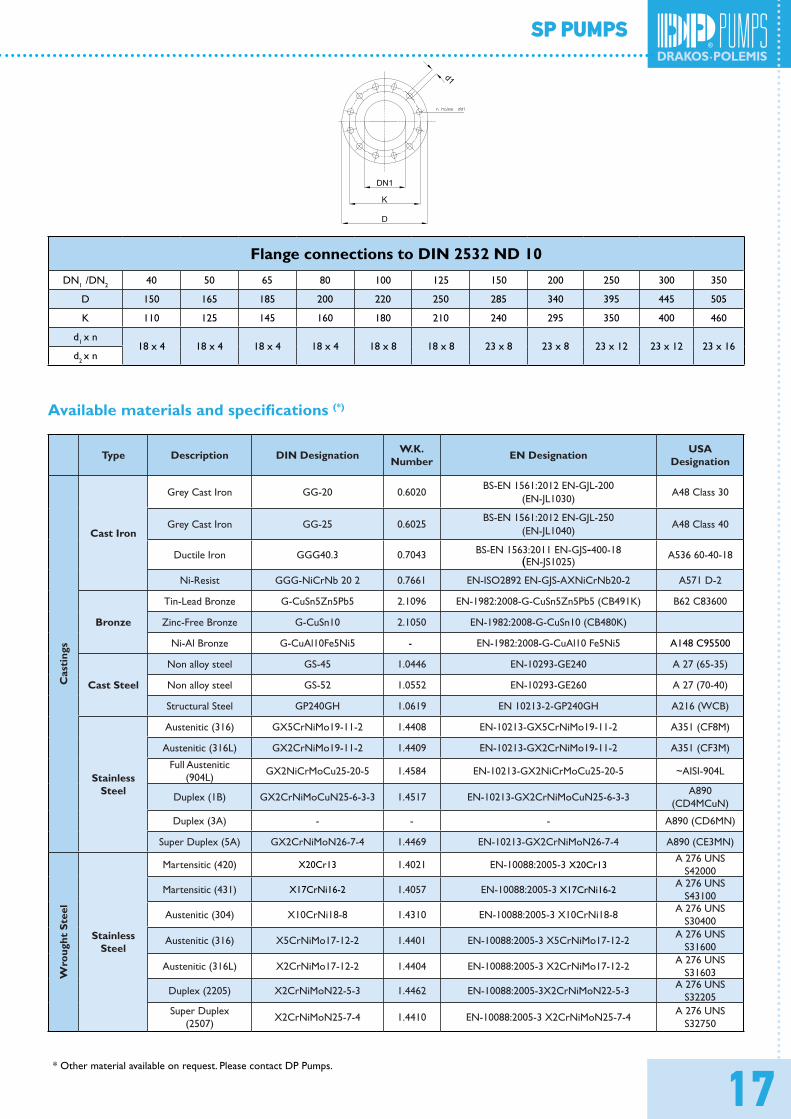
Flange connections to DIN 2532 ND 10DN1 /DN2 40 50 65 80 100 125 150 200 250 300 350
D 150 165 185 200 220 250 285 340 395 445 505
K 110 125 145 160 180 210 240 295 350 400 460
d1 x n18 x 4 18 x 4 18 x 4 18 x 4 18 x 8 18 x 8 23 x 8 23 x 8 23 x 12 23 x 12 23 x 16
d2 x n
Available materials and specifications (*)
Type Description DIN Designation W.K.Number EN Designation USA
Designation
Cas
ting
s
Cast Iron
Grey Cast Iron GG-20 0.6020 BS-EN 1561:2012 EN-GJL-200
(EN-JL1030)A48 Class 30
Grey Cast Iron GG-25 0.6025BS-EN 1561:2012 EN-GJL-250
(EN-JL1040)A48 Class 40
Ductile Iron GGG40.3 0.7043 BS-EN 1563:2011 EN-GJS-400-18(EN-JS1025)
A536 60-40-18
Ni-Resist GGG-NiCrNb 20 2 0.7661 EN-ISO2892 EN-GJS-AXNiCrNb20-2 A571 D-2
Bronze
Tin-Lead Bronze G-CuSn5Zn5Pb5 2.1096 EN-1982:2008-G-CuSn5Zn5Pb5 (CB491K) B62 C83600
Zinc-Free Bronze G-CuSn10 2.1050 EN-1982:2008-G-CuSn10 (CB480K)
Ni-Al Bronze G-CuAl10Fe5Ni5 - EN-1982:2008-G-CuAl10 Fe5Ni5 A148 C95500
Cast Steel
Non alloy steel GS-45 1.0446 EN-10293-GE240 A 27 (65-35)
Non alloy steel GS-52 1.0552 EN-10293-GE260 A 27 (70-40)
Structural Steel GP240GH 1.0619 EN 10213-2-GP240GH A216 (WCB)
StainlessSteel
Austenitic (316) GX5CrNiMo19-11-2 1.4408 EN-10213-GX5CrNiMo19-11-2 A351 (CF8M)
Austenitic (316L) GX2CrNiMo19-11-2 1.4409 EN-10213-GX2CrNiMo19-11-2 A351 (CF3M)
Full Austenitic(904L) GX2NiCrMoCu25-20-5 1.4584 EN-10213-GX2NiCrMoCu25-20-5 ~AISI-904L
Duplex (1B) GX2CrNiMoCuN25-6-3-3 1.4517 EN-10213-GX2CrNiMoCuN25-6-3-3 A890(CD4MCuN)
Duplex (3A) - - - A890 (CD6MN)
Super Duplex (5A) GX2CrNiMoN26-7-4 1.4469 EN-10213-GX2CrNiMoN26-7-4 A890 (CE3MN)
Wro
ught
Ste
el
StainlessSteel
Martensitic (420) X20Cr13 1.4021 EN-10088:2005-3 X20Cr13 A 276 UNS
S42000
Martensitic (431) X17CrNi16-2 1.4057 EN-10088:2005-3 X17CrNi16-2 A 276 UNS
S43100
Austenitic (304) X10CrNi18-8 1.4310 EN-10088:2005-3 X10CrNi18-8 A 276 UNS
S30400
Austenitic (316) X5CrNiMo17-12-2 1.4401 EN-10088:2005-3 X5CrNiMo17-12-2 A 276 UNS S31600
Austenitic (316L) X2CrNiMo17-12-2 1.4404 EN-10088:2005-3 X2CrNiMo17-12-2 A 276 UNS S31603
Duplex (2205) X2CrNiMoN22-5-3 1.4462 EN-10088:2005-3X2CrNiMoN22-5-3 A 276 UNS S32205
Super Duplex(2507) X2CrNiMoN25-7-4 1.4410 EN-10088:2005-3 X2CrNiMoN25-7-4 A 276 UNS
S32750
* Other material available on request. Please contact DP Pumps.
18
SP PUMPS
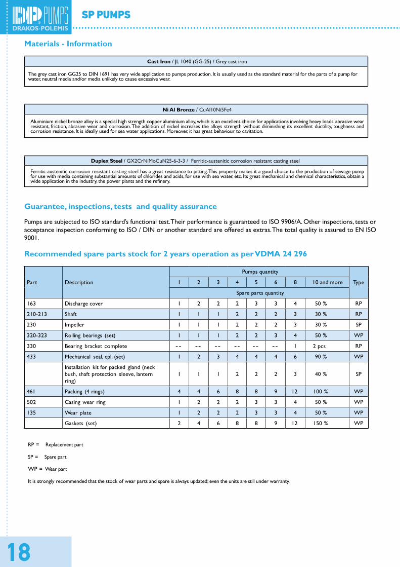
Materials - Information
Cast Iron / JL 1040 (GG-25) / Grey cast iron
The grey cast iron GG25 to DIN 1691 has very wide application to pumps production. It is usually used as the standard material for the parts of a pump for water, neutral media and/or media unlikely to cause excessive wear.
Ni Al Bronze / CuAl10Ni5Fe4
Aluminium nickel bronze alloy is a special high strength copper aluminium alloy, which is an excellent choice for applications involving heavy loads, abrasive wear resistant, friction, abrasive wear and corrosion. The addition of nickel increases the alloys strength without diminishing its excellent ductility, toughness andcorrosion resistance. It is ideally used for sea water applications. Moreover, it has great behaviour to cavitation.
Duplex Steel / GX2CrNiMoCuN25-6-3-3 / Ferritic-austenitic corrosion resistant casting steel
Ferritic-austenitic corrosion resistant casting steel has a great resistance to pitting. This property makes it a good choice to the production of sewage pump for use with media containing substantial amounts of chlorides and acids, for use with sea water, etc. Its great mechanical and chemical characteristics, obtain awide application in the industry, the power plants and the refinery.
Guarantee, inspections, tests and quality assurance
Pumps are subjected to ISO standard’s functional test. Their performance is guaranteed to ISO 9906/A. Other inspections, tests or acceptance inspection conforming to ISO / DIN or another standard are offered as extras. The total quality is assured to EN ISO9001.
Recommended spare parts stock for 2 years operation as per VDMA 24 296
Part Description
Pumps quantity
Type1 2 3 4 5 6 8 10 and more
Spare parts quantity
163 Discharge cover 1 2 2 2 3 3 4 50 % RP
210-213 Shaft 1 1 1 2 2 2 3 30 % RP
230 Impeller 1 1 1 2 2 2 3 30 % SP
320-323 Rolling bearings (set) 1 1 1 2 2 3 4 50 % WP
330 Bearing bracket complete -- -- -- -- -- -- -- -- -- -- -- -- 1 2 pcs RP
433 Mechanical seal, cpl. (set) 1 2 3 4 4 4 6 90 % WP
Installation kit for packed gland (neck bush, shaft protection sleeve, lanternring)
1 1 1 2 2 2 3 40 % SP
461 Packing (4 rings) 4 4 6 8 8 9 12 100 % WP
502 Casing wear ring 1 2 2 2 3 3 4 50 % WP
135 Wear plate 1 2 2 2 3 3 4 50 % WP
Gaskets (set) 2 4 6 8 8 9 12 150 % WP
RP = Replacement part
SP = Spare part
WP = Wear part
It is strongly recommended that the stock of wear parts and spare is always updated; even the units are still under warranty.

