applied optics 2 - physics.muni.cz
TRANSCRIPT

applied optics 2
mgr. dušan hemzal , ph.d.
web: http://www.physics.muni.cz/~hemzal/vyuka/optometry
applied optics 1:properties of light
geometrical optics
polarisation and intensity of light
birefringenceinterference diffraction of lightscattering of light
applied optics 2 : application of light
sources and detectors of lightblack body radiation, Bohr’s model of atom, light bulb, discharge lamp, X-ray tube, lasers, H-D curve, CCD, angiograph
polarisation of light polarisation microscope, GDx
interference and diffraction biometry of the eye, OCT
wavefronts and aberrations Seidel’s aberrations, Zernike polynomials, wavefronterror, classification of aberrations, WASCA
basic microscopy methods bright field, dark field, Nomarsky contrast, immersion fluid, condensor, endotellium microscope
scanning methods depth of field, confocal microscope, HRT, scanning techniques, CSLO

light sources
stimulated emission ( lasers)
type of emission spectrum
atomary emission line/continuous
thermal emission characteristic/contin.
luminiscence ~ monochromatic
Čerenkov radiation continuous
annihilation polychromatic
black body radiation
maximum of radiated energy
][
898,2max KT
mm=λ (Wien’s law)
overall amount of radiated energy4Tj σ≈
atomary emission, bremsstrahlung Čerenkov radiationcharacteristic radiation
(Stefan-Boltzmann law)
4218 KmJs10x67.5 −−−−=σ
http://glossary.periodni.com/glossary.php?en=
blackbody+radiation

light bulb
evacuated bulb with tungsten filament + nitrogen/argon atmosphere
electric current heats the filament to (2000 K – 3000 K)
cca 97% of energy is radiated in IR, only 3% in visible part of the spectrum
lifetime of bulb is limited by tungsten evaporation
for common use, light bulbs are being replaced (LED sources)
filament
supports
nozzle
connection wiressealing
evacuation tube
socket
contact
positive charge is concentrated in the nucleus, which occupies only a small fractionof atom volume (and is stabilized by presence of neutrons)
electrons orbit the nucleus using circular trajectories (or, at spherical shells)
0
2
2
22
aZ
n
Zmek
nr
een == h
specific energy is prescribed to every orbit
2
2
eV6.13n
ZEn −=
the energy difference during electron transition be tween two orbitals is always accounted for by photon of appropriate wavel ength(emission or absorption, depending on the direction of transition)
where a0=0,522 Å is the Bohr’s radius(the radius of first shell in hydrogen)
-13,6 eV is the energy at first shellof hydrogen
1 Å = 10-10 m = 0.1 nm
negative energies mean the electron is binded to the atom
Bohr’s model of atom
the radii of the orbits are fixed if the atoms are to be stable(radiative losses)
||/]J[]eV[ eEE =

X-ray tube
acce
lera
ting
volta
gefilament voltage
characteristic radiation : depends on the material of anodeindependent of accelerating voltage
bremsstrahlung : independent of anode materialdepends on accelerating voltage
breaking radiation cutoff:
Ve
hc
⋅=minλ (Duane–Hunt law)
X-rays
- evacuated tube with electrodes of special shape(filament cathode and disc anode)
- electric current heats the cathode up to creating free elecrons- accelerating voltage directs the free leectrons toward the anode
(impact speed of electrons at anode is more than 150 000 km/s at 100 kV)
- the heavier material of anode, the harder X-ray radiation is produced
filament
free electrons
X-rays
gap afterelectron ejection
X- rays
during interaction of electrons with anode, two processes take place:
- scattering of X-ray light connected with the bremsstrahlung- production of characteristic radiation , connected with ejection
of electrons (close to the nucleus) and subsequent refilling of the gaps
stimulated emission – lasers
usually, excited states lifetimes are very short (about 1 ns), butoccasionally, excited states are meta-stable (lifetimes about 1000 ns)
with sufficient optical pumping , electrons can be mustered at the meta-stable levelinversion of state : occupation of excited state is higher than that of base stateafter random spontaneous emission, electrons exhibit chain de-excitaion viastimulated emission as perfect copies of the original photon
length of resonator selects the allowed wavelength of photons:
as well as (together with mirrors used) the spectral line-width:
apart from stimulation, laser uses a common type at omic emission
by combination of meta-stable transitionspectral width and resonator modes widthextremely narrow linewidth of laser is produced
using suitable mirror coating, only the central mode can be selected –laser becomes super coherent
tuning of the mirrorsguarantees collimatedlaser beam

He-Ne laser
wavelength 632,8 nm, continual,laser power up to 50 mW
a mixture of helium and neon in evacuated tube
pumping is realised by starting a dischargein the tube
pumping excites mostly helium, the energy ispassed to neon (meta-stable levels) by collisions
laser pumping regime application
He-Ne
(N - CO2)optical (discharge)
continual, 632,8 nm
(continual, 1060 nm)
basic type laser
ruby laser: Al2O3 – Cr optické (ionisation) pulsed, 694,3 nmtattoo removal
ion lasers : argon
(krypton)optical (discharge)
continual, 488 nm, 514 nm
continual, VIS
coagulation (retina)
Nd:YAG optical pulsed, 1064 nm iridotomy
excimer lasers.: ArF
KrF (XeF,…)chemical reaction
pulsed, 193 nm
pulsed, 248 nm (353 nm)
ablation, LASIK
dye lasers: rhodamine 6G,
stilbeneby another laser
pulsed, 570-640 nm
pulsed, 390-435 nm
tunable lasers
removal of moles
low-pressure (neon) tube (tenths of kPa) with separate electrodescolor depends on gas composition (99.5 % neon, 0.5 % argon)starting voltage about 120 V
with DC, only one electrode glowswith AC, both electrodes glow (as voltage changes sign)power consumption is small
ignited by touching of the electrodes and their subsequent withdrawal
can be produced in various atmospheres
problem: high current between electrodes make them burn away (anode 4x faster than cathode)
most of the light come from heated electrodes(anode 90%, cathode 8%, discharge itself 2%)
high intensity discharge
gas discharge
discharge lamp : evacuated tube with electrodes, secondarily filled with gasupon ionization , a permanent discharge can be ignited in gas
- ionisation by voltage: glow discharge (ionisation by accelerated electrons)- thermal ionisation: (spark) discharge
after ignition, discharges tend to be self-sustaining

within 24 hours of fluorescein application, irradiation by green lasers (Ar-ion) is avoided
luminiscence
Stokes law: luminescence emission always takes plac e at wavelength higher thanthat of the absorbed light
luminiscence is a common designation for light emission following some light absorptionmeanwhile non-radiative de-excitation also takes place
luminescent response is delayed from absorption, for longer delays we use the term phosphorescence
fundus camera and fluorescein angiography
illumination of retina can be achived using thefundus camera
- special microscope serves as objective- strong source of flash light is needed
it is convenient to perform both measurements simultaneously
fluorescence : emissive response of material to illuminationdelayed by milisecondsred-shifted w.r.t. excitation
for longer delays (seconds or even more) we use term phosphorescence
some tissues act as natural fluorophores, short illumination then suffices to trigger the response
or, artificial fluorophore can be supplied intravenously, eg
fluorescein absorbs in blue part of the spectrum (485-500 nm) and emits in green part of the spectrum (525-530 nm)
indocyanine green (ICG) has absorbtion maximum near 800 nm andemits light near835 nm (ie. whole phenomenon takes place in IR)

detection of light
photographic emulsion
- photosensitive layer of halogenides of silver (eg. AgBr)- in reaction to illumination, the silver is reduced(latent image is produced – amount of reduced silver too small to be visible)
- role of the developer (eg. Na2S2O3.5H2O) is to seek theplaces where silver has already been reduced andthere multiply the amount of reduced silver (about billion times)
- the fixer changes the remaining AgBr into water soluble salt,which is subsequently washed away (together with gelatine matrixsupporting the photosensitive layer)
- developing of the film must be stopped in due timethe response both to illumination and to developing isdescribed by the general Hurter-Driffield curve
the eyeresponse time 0,1sdetection via electrochemical chain
photographic emulsion works also with X-ray
insensibilised films are almost insensitive to green lightsensibilisation: ortochromatic, panchromatic
coloured film: three suitably sensibilised layers atop one another
sensitivity of detectors can be measured as s[ASA]; for a correct exposition time t[s] of the observed scenethe exposition need [EV] is introduced through
where c is the speed of the objective used.clearly, shift of exposition need by 1EV changes exposition time by factor of 2 (with c fixed)
exposition need of usual scenes is known (or can be measured), it is convenient to refer the value to a fixed detector sensitivity (say, 100ASA); for other speeds, one has
by combination of the two formulas one finally has
common scenes range from EV100 = 16 (sunlit snow) to EV100 = -9 (Milky Way).
apart from exposition need, every scene also posses some exposition extent [ASA] describing the fluctuation of the formerwithin the scene:
dynamic range of the detectorexposition extent of the sceneexposition flexibility of the detector for the given scene
t
cSEV
2
2 =
1002 100
sEVEVS =−
1002100
2
EVsc
t =
detection of light

dark tones in image are missingthe image contrast is lowered
software repair is possible(to some extent)contrast is improved, butcolors get (slightly) unnatural
CCD (Charge Coupled Device)
uses photoefect, descendant of a photodiode:impacting light produces free electrons, that can be counted to provide relative measure of light intensity
condition for photon capture:
the work function A is a constant of each material, usually tenths to units of eV
technically, a CCD detector is realized by a MOS type semiconductor organized into distinct electrodes
to achieve colored image, RGB masking is used (which decreases resolution of the chip)
by suitable voltage gating the freed electrons can be held below the electrodeafter exposition, clocking of the voltage shifts the pixels towards read out
detection of light

photographic objective
focal length
diameter of aperture
objective speed
from imaging equation: the farthest object are focused closest to the objectiveas the objective mount is limited in travel, there existsthe closest focusable point (amin)
macro regime: by shifting of inner lenses within objective,objects closer than amin can be focused
the size of image of a distant point can be estimated as
ξtanfo =&
Dfc
D
f
/=
D
where is the angle, under which we observe the object
o
ξ
another solution: secondary lens
objective mount
the distance of objective from detector selects which objects will be sharply imaged
22
2
44 cD
fl ==λ
cD
fd
ππλ8317.38317.3 ==
depth of field
a perfect optical system images a point object into a point imagein the vicinity of this point image the rays form a cone, whose angle depends on the aperture
in real optical system the image is hampered at least by diffraction the original cone with sharp tip at the image is replaced by a diffraction tunnel whose waist opens only slowly and is surrounded by diffraction minima and maxima
length of the diffraction tunnel:
diffraction tunnel waist :
paprsky objectivev okolí speedohniska c = f/d

confocal microscope
principle of the method: an aperture iris is introduced into the conjugate focus to the observed point. The opening of the iris is very small, and thus strongly limiting rays from other points.
the iris is (piezo) moved, so in result, a full 3D image can be takenalbeit point by point, which is slow
patented 1957
usually, fluorescent image is taken
the image is processed by a computer
as the image is taken point by point, confocal microscopegenerally belongs to the class of scanning microscopes
Heidelberg Retina Tomograph (HRT II, III), 2005
measurement can be performed through glasses/contact lenses, dilatation of pupil is not necessary
confocal microscope setup, thatenhances the fundus camera possibilitiesis suitable for glaucoma diagnosis
provides objective informationallows for progression monitoring
semiconductor laser, 670 nmfield of vies 15°x15°, centred to papilla of optical nerve
scans 384x384 points16-64 layers of depth
triple repeat (statistics)
3D image is computed automaticallyoptic disc is segmented manually by an ophthalmologist
consequently, the computer calculates the relevant characteristics(usually in six angular segments):size and shape of disc and cup, thickness of retinal layer, excavation
data can be checked again database, important is also a comparison of left/right eye

scanning microscopy techniques
when imaging large areas, it is convenient to take several subpictures which are aligned to final image
the aberration are easier to treat for smaller fields of view, but higher mechanical stability is required
scanning optics:
mechanical (slow): Nipkow disc, piesoelectrics
optical (faster, without mechanical vibrations):
Kerr cell, Pokelson cell, ultrasound bending of light
confocal scanning laser ophthalmoscope (CSLO) 1979
objective is the eye itself
allows imaging of individual photo-receptors at retina
images about 1,5° of retina with 30 scans/second
utilisation of adaptive optics allows to eliminate the aberrations of the eye (and distinguish thetypes of receptors)
used for direct observing of scotoms and retinal faults
for fast detection, CCD is almost exclusively used
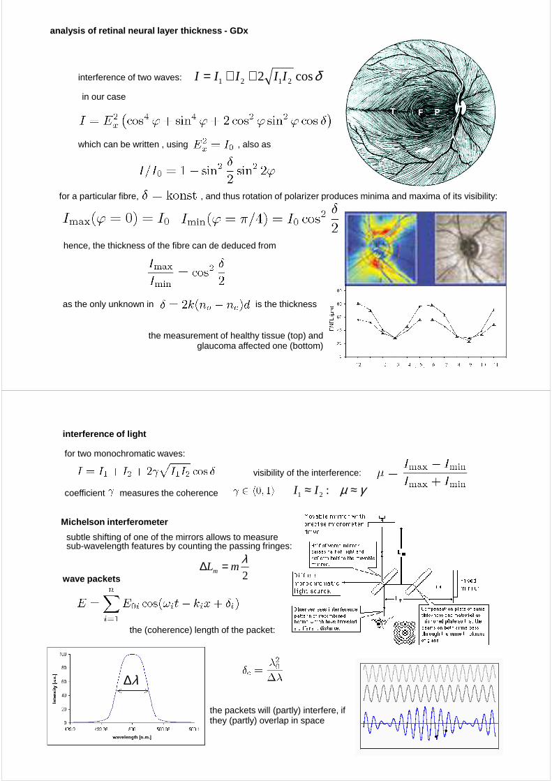
analysis of retinal neural layer thickness - GDx
the neural fibres are naturally birefringent(thanks to prolonged molecules in their shields)
for polarization microscopy, optical axes must be perpendicularto the line of sight – just the case of fibres at retina
as the light needs to be reflected (passing the neural layerforth and back), usually polarizer serves also as (parallel) analyser
1) after entering the birefringent fibre
2) after reflection from fibre back-side
3) after analyser
after polariser
both waves are now polarized in the same direction ad thanks to small thickness of fibresordinary and extra-ordinary rays remain coherent: interference takes place with phase shift
as the only unknown in is the thickness
interference of two waves:
in our case
which can be written , using , also as
for a particular fibre, , and thus rotation of polarizer produces minima and maxima of its visibility:
hence, the thickness of the fibre can de deduced from
δcos2 2121 IIIII ++=
the measurement of healthy tissue (top) and glaucoma affected one (bottom)
analysis of retinal neural layer thickness - GDx
interference of light
for two monochromatic waves:
coefficient measures the coherence
subtle shifting of one of the mirrors allows to measuresub-wavelength features by counting the passing fringes:
visibility of the interference:
γµ ≈≈ :21 II
2
λmLm =∆
wave packets
the (coherence) length of the packet:
λ∆
the packets will (partly) interfere, if they (partly) overlap in space
Michelson interferometer

interferometric measurement of thickness
consider Michelson interferometer with moving mirror, sample of thickness x and refractive index nwe use the wave-packets picture:
the wave directly reflected packet (orange) and back-side reflected packet (green) will onlyinterfere, when they succeed to meet both in space and time. the phase difference in flight, caused by the sample thickness can be compensated by movingthe interferometer armby scanning the full range of the arm movement, several peaks of interference visibility are observed,from which the thicknesses of individual layers within sample can be deduced
0=∆d 0≈∆d nxd 2≈∆higher order reflections are difficult to observe (their intensity is low)
Lm
Lf
optical biometry of the eye
IOL Master – performs interferometric measurement of structures within the eyeusing the wave-packets of suitable length
resolution in thickness: 0.02 mm
the method is non-contact: measurement can take place through glassesor, even through cataract
the output of measurement consists in dependence of interference visibility on the interferometer arms position
decomposition into possible reflecting surfaces is performed by a computer
the precision (stability) of the decomposition is highly improved (at sake of computational load) if multiple reflections can be taken into account

Optical Coherence Tomography (OCT), 1991
OCT = source of diffuse spectrum + interferometer + scanning optics
the depth and lateral resolutions are detached:
depth resolution : dependson packet length only
lateral resolution : depends on optics used
( ) cδπλ
λπ
2ln222ln
2
0 =∆
semiconductor laser diode, 800 – 1000 nm, hundreds of mW
for an objective with focal length fand numerical aperture NA:
NAx 037.0
λ=∆
Optical Coherence Tomography (OCT), 1991
( )kztkEkE −= ωcos)()( 0
2rr rR =
1S
211 SS rR =
( )]2[cos2
)(0 dlzktrkE
mr ++−ω
( )]2[cos2
)(1
0 dlzktrkE
fS ++−ω
( ) ])[2cos(24
)(101
0mfSrSr llkRRIRR
kII −++=
2S
two successive maxima:
π2)(2 cllk mf =−
π2)1()(2 +=−′ cllk mfmf ll
kkk−
=−′=∆ π
2
41Sr RR +
mf ll −π

wavefront aberration in axially symmetric systems
based on the symmetry, rotating the system around the optical axis must produce no visible effect
only combinations of scalar products can be present
( )000 , yxx =r ( )yxx ,=r
in polar coordinates
xxxxxxrrrrrr ⋅⋅⋅ ,, 000
without loss of generality, we can set 00 =y
ϑρ cos=x ϑρ sin=y
( ) ( )220
2000 ,,,,, yxxxxHyxyxH +→wavefront aberration:
special case: axial (point) source:
x; yx0; y0
(y0 = 0)
ρ is the aperture radius
+++++ θρθρρ 2220222
30131
4040
40400 coscos xWxWWxW
Seidel’s aberrations 1856 (axially symmetric systems)
advantage of Seidel coefficients:
the overall aberration of every kind is just a sum of contributions from individual surfaces:
the lowest (third) order terms:
spherical aberration S I , coma S II , astigmatism S III , curvature S IV , distortion S V
piston, tilt and defocus are not aberrations (they do not disturb point imaging)
within higher orders, new types of aberrations are introduced (elliptic coma, …)
( ) ϑρρϑρϑρρ cos2
1
4
1cos
2
1cos
2
1
8
1 30
220
2220
30
4 xSxSSxSxSSH VIVIIIIIIIII +++++=
SI = S1I + S2
I + S3I + S4
I + : : :eg. etc.
yρ
P z
y
P′
H (y)transversal aberration:
transversal aberration describes change of image position within image plane
( )x
yxHfx ∂
∂−= ,ρ ( )y
yxHfy ∂
∂−= ,ρ

aberrations of human eye
Zernike polynomials (1934)
drawback: information on position of the source is suppressedfor a complete aberrational description, several measurements are needed
advantage: individual terms do not interfere – addition of one polynomial does not disturb the other aberrations
one Zernike polynomial comprises several Seidel aberrations, and vice versa
well suited for aberrations of the eye description, other systems (turbulent media, brilliant cutting)may be better described by other systems
we stat again from wavefront description using the polar coordinatesin the plane of exit pupil:
motivation: information is needed in more detail than keratograph can provide
also, axial symmetry is nor present within eyeon the other hand, pupil is almost perfectly circular
θρθρ sin,cos == yx
( ) ( )θρ mn
mn
mn RZ Φ=( ) ∑ ∑
= −=
=k
n
n
nm
mn
mn ZWH
1
,θρ
individual Zernike polynomials and the wavefront er rors produced:
axially symmetric aberrations are locatedon the axis of the triangle
‘diamond’ of Seidelaberrations stretchesover several lines lower aberrations
higher aberrations

WASCA (WAve Aberration SCAnner)
Hartmann-Shack sensor
generalization of examination using single spherocylindrical lens
either two crossed rows of linear lamels, or directly a 2D etched system of micro-lenses (lenslet array)
each lenslet focuses a small piece of wavefrontin this way, waveront aberrations is visualised throughirregularity in the 2D grid of focused pointscommon parameters: 15-1000 μm/lens diameter, accuracy of focus: +- 3%, substrate: (Si,Ge, ZnS) 1-6 mm thick
PSP (Point Spread Function):shape of the real image of point source of light
in combination with LASIK, aberrations up to 20th ordercan be corrected (not the case in practice – progression)
intensity of detector illumination
1. minimum
1. maximum
2. minimum
2. maximum
diffraction over circular aperture of radius R:
resolution limit of the objective
resolution of common detectors: the eye (1 arc minute), photographic film (100 lines/mm), CCD (size of the pixel: 1-5 µm)
similar considerations hold for imaging of moving objects:motional blur appears (blood flow etc.)
Rayleigh limit of resolution:
two point sources can bedistinguished, if their imagesare at least the diameter of Airy’s disc apart
Airy
disc
minima of intensity at the detector:3.83, 7.02, 10.17, 13.32, 16.47…
)/( 02 rkRfI ρ≈
in terms of angular separation: [ ]mm
414
Dk
′′=ξ
first maximum (the Airy disc) contains about 80% of transmitted light
0/ rkRx ρ=

illumination of microscopy samples
light bulbs: wolfram filament(halogen bulbs: wolfram filaments + iodine cycle)
discharge lamps: significant emission in UVintense sources + good for luminescence trigering
filters: coloured - monochromatic, can improve image sharpnessgray (ND) - overall intensity tuning, can improve contrast
Lieberkuhn mirror
condenser serves to
homogenise light (intensity), creation of plane wavefront increase the numerical aperture (and thus also the resolution of microscope)allow for advanced microscopy techniques
condensers can be constructed for both transmitted and reflected lightthe advanced techniques are usually realised through filter wheelscondenser can be the most expensive part of the microscope
0
0
0
0min A
CAA
dC
λλ =+
= 15.0 ÷≈C
immersion objectives
through numerical aperture, the diffraction spot size dependson refractive index o the medium between objective and sample:
one way of shifting the resolution limit is to use shorter wavelength light
the other is to introduce (immersion) medium with n>1 betweenobjective and sample:
yet another possibility is to make use of condenser
(altogether, by application of all possible improvements, about a quarter of a wavelength can be resolved )
medium n
air 1,0003
water 1,33
immersion oil 1,515
bromnaphtalene 1,658
metyleniodid 1,740
αλλ
sin
22,122,1min nNA
d ==
immersion objectives are explicitly prepared for contact with fluids(and are usually marked around by a colored line)
the resolution enhancement upon using immersion fluids comes from collecting higher angle rays

dark field (transmission and reflection)
reminder: HRT also works in dark field
dark field: a hollow light beam is created within condenser,which reaches sample at an oblique angle, whichis designed such, that these rays cannot be collectedby the objective
hence, only light scattered by the sample can aid inconstructing the image (scattering is omni-directional)
the hollow light beam is initiated using concave mirrorsimilar construction can be reached in reflected light
bright filed: almost all light rays from source are used for creating an image; when no sample is present.homogeneously lit field (bright field) is observed
after sample loading, the viewed contrast is created by absorbing parts of the sample
samples with neglibigle absorption contrast get invisible using tis method
phase contrast (Zernike 1930, Nobel prize 1953)
samples, that exhibit both little absorption and little scattering will still be almost invisiblefinal solution: slight changes in refractive index need to be visualised
inhomogeneous refractive index causes both deviatio n andphase difference between any two originally close r ays
the task of the microscope is to transfer the phase shift into intensity contrast
within condenser, ring with annular opening is placed – hollow light beam iscreated again, but this time, it is allowed to reach the objective (without phaseshift)
after the sample, a secondary phase-plate is inserted which mixesthe inner (phase modified) and outer light rays:
for biological samples, partial solution would be cell stainingbut stained cells die
( )[ ]ϕ∆+≈′ 2sin12ss aI

DIC (differential interference contrast)
Wollaston prism
usually a crystal of calcite CaCO3,
cut, turned and glued back
due to birefringence, ordinary and extra-ordinary rays are created
thanks to prism geometry these to rays are slightly divergent butstart with identical phase shift
improvement of phase contrast modality: removal of the halo
especially useful for samples creating about λ/4 phase shift
using additional collimation optics, the sample is illuminated by pairs of parallel raysabout 0,2 μm separated.
in effect, two slightly shifted images are obtained, which are formed by cross-polarizedlight (to exclude interference within sample)
the second prism joins the rays whichresults in pseudo 3D difference image
the filter wheel equipped for variousmicroscopy techniques (left)
Nomarsky contrast
nomarského hranol
bright fieldimage
dark fieldimage
Nomarsky contrast
phase contrast